Embed Size (px)
Citation preview

www.ElectroluxUSA.com
Ref
rige
rato
rsEl
ectro
lux
Icon
Built
-In S
ide
by S
ide
DA99-00689C REV(0.0)
La section française commence à la page 45
RéfrigérateursElectrolux Icon Côte à Côte
Model 42
Write the model and serial numbers here:
Model # __________________________
Serial # __________________________
Find these numbers on a label inside the refrigerator compartment at the top on the right side.
Owner’s Manual and Installation Instructions
Manuel d’utilisationet d’installation
La sección en español empieza en la página 87
RefrigeradoresElectrolux Icon Lado a Lado
Manual del propietario e instalación
Safety Instructions . . . . . . . . . . .2–4
Operating InstructionsAutomatic Icemaker . . . . . . . . . . .10Care and Cleaning . . . . . . . . . .12, 13Drawers and Baskets . . . . . . . . . . . .9Ice and Water Dispenser . . . . .10, 11Refrigerator Doors . . . . . . . . . . . . .8Replacing the Light Bulbs . . . . . . .14Shelves and Bins . . . . . . . . . . . . . . .7Temperature Controls . . . . . . . . . . .5Water Filter . . . . . . . . . . . . . . . . . . .6
Installation InstructionsAnti-Tip Brackets . . . . . . . . . . . . . .30Dimensions, Clearances . . . . . . . .17Door, Grille Panels . . . . . . . . .32, 33Installation Space . . . . . . . . . . . . .17Leveling . . . . . . . . . . . . . . . . . . . . .31Panel Dimensions . . . . . . . . . .21–26Stainless Steel Handles . . . . . . . . .34Water Line . . . . . . . . . . . . . . . . . . .29Water Supply . . . . . . . . . . . . . . . . .35
Troubleshooting Tips . . . . . . .38–40Normal Operating Sounds . . . . . .37
Consumer SupportPerformance Data Sheet . . . . . . . .42State of California Water Treatment Device Certificate . . . . .43Warranty . . . . . . . . . . . . . . . . . . . .41

Cons
umer
Sup
port
Trou
bles
hoot
ing
Tips
Oper
atin
g In
stru
ctio
nsSa
fety
Inst
ruct
ions
Inst
alla
tion
Inst
ruct
ions
2
IMPORTANT SAFETY INFORMATION.READ ALL INSTRUCTIONS BEFORE USING.
WARNING!Use this appliance only for its intended purpose as described in this Owner’s Manual.
SAFETY PRECAUTIONSWhen using electrical appliances, basic safety precautions should be followed, including the following:
■■ This refrigerator must be properly installed and located in accordance with the InstallationInstructions before it is used.
■■ Do not allow children to climb, stand or hang on the shelves in the refrigerator. They coulddamage the refrigerator and seriously injurethemselves.
■■ Do not touch the cold surfaces in the freezercompartment when hands are damp or wet. Skinmay stick to these extremely cold surfaces.
■■ Do not store or use gasoline or other flammablevapors and liquids in the vicinity of this or anyother appliance.
■■ In refrigerators with automatic icemakers, avoid contact with the moving parts of the ejector mechanism, or with the heating elementlocated on the bottom of the icemaker. Do notplace fingers or hands on the automaticicemaking mechanism while the refrigerator is plugged in.
■■ Keep fingers out of the “pinch point” areas;clearances between the doors and between the doors and cabinet are necessarily small. Be careful closing doors when children are in the area.
■■ Set the master power switch to the O (off) positionbefore cleaning or making repairs.
NOTE: We strongly recommend that any servicing beperformed by a qualified individual.
■■ Do not refreeze frozen foods that have thawed completely.

Consumer Support
Troubleshooting TipsOperating Instructions
Safety InstructionsInstallation Instructions
ElectroluxUSA.com
PROPER DISPOSAL OF THE REFRIGERATORChild entrapment and suffocation are not problemsof the past. Junked or abandoned refrigerators arestill dangerous…even if they will sit for “just a fewdays.” If you are getting rid of your old refrigerator,please follow the instructions below to help preventaccidents.
Before You Throw Away Your Old Refrigeratoror Freezer:■ Take off the doors.
■ Leave the shelves in place so that children maynot easily climb inside.
RefrigerantsAll refrigeration products contain refrigerants, which under federal law must be removed prior to product disposal. If you are getting rid of an old refrigeration product, check with thecompany handling the disposal about what to do.
DANGER! RISK OF CHILD ENTRAPMENT
3

4
Cons
umer
Sup
port
Trou
bles
hoot
ing
Tips
Oper
atin
g In
stru
ctio
nsSa
fety
Inst
ruct
ions
Inst
alla
tion
Inst
ruct
ions
IMPORTANT SAFETY INFORMATION.READ ALL INSTRUCTIONS BEFORE USING.
WARNING!HOW TO CONNECT ELECTRICITYDo not, under any circumstances, cut or remove the third (ground) prong from the power cord. Forpersonal safety, this appliance must be properly grounded.
The power cord of this appliance is equipped with a 3-prong (grounding) plug, which mates with a standard 3-prong (grounding) wall outlet to minimize the possibility of electric shock hazardfrom this appliance.
Have the wall outlet and circuit checked by aqualified electrician to make sure the outlet isproperly grounded.
If the outlet is a standard 2-prong outlet, it is yourpersonal responsibility and obligation to have itreplaced with a properly grounded 3-prong walloutlet.
The refrigerator should always be plugged into itsown individual electrical outlet which has a voltagerating that matches the rating plate.
This provides the best performance and alsoprevents overloading house wiring circuits, whichcould cause a fire hazard from overheated wires.
Never unplug your refrigerator by pulling on thepower cord. Always grip plug firmly and pull straightout from the outlet.
Repair or replace immediately all power cords thathave become frayed or otherwise damaged. Do notuse a cord that shows cracks or abrasion damagealong its length or at either end.
When moving the refrigerator, be careful not to rollover or damage the power cord.
DO NOT USE AN ADAPTER PLUG OR EXTENSION CORD (Adapter plugs not permitted in Canada)
Do not use an adapter plug to connect the refrigerator to a 2-prong outlet.Do not use an extension cord with this appliance.
READ AND FOLLOW THIS SAFETY INFORMATION CAREFULLY.SAVE THESE INSTRUCTIONS

Consumer Support
Troubleshooting TipsOperating Instructions
Safety InstructionsInstallation Instructions
About the temperature controls. ElectroluxUSA.com
The temperature controls are preset in the factory at 37°F for therefrigerator compartment and 0°F for the freezer compartment. Allow24 hours for the temperature to stabilize to the preset recommendedsettings.
The actual temperature may vary slightly from the set temperaturebased on usage and operating environment.NOTE: The refrigerator is shipped with protective film covering thetemperature controls. If this film was not removed during installation,remove it now.
The Performance Air-Flow System is designed tomaximize temperature control in the refrigeratorand freezer compartments. This unique specialfeature consists of the Air Tower along the back
wall of the refrigerator and the freezer. Placing foodin front of the louvers on these components will notaffect performance.
Performance Air Flow System
To change the temperature, press and release theup or down arrow button. To change thetemperature, tap either the up arrow for warmertemperatures or the down arrow for coldertemperatures until the desired temperature isdisplayed. Refrigerator temperatures can beadjusted between 34 °F and 47°F and the freezertemperatures can be adjusted between -6 °F and +8°F.
Once the desired temperature has been set, the temperature display will clear after 60 seconds.
To display the temperature, the Disp Temp buttonmay be tapped.
Several adjustments may be required. Each time youadjust controls, allow 24 hours for the refrigerator toreach the temperature you have set.
5

Cons
umer
Sup
port
Trou
bles
hoot
ing
Tips
Oper
atin
g In
stru
ctio
nsSa
fety
Inst
ruct
ions
Inst
alla
tion
Inst
ruct
ions
About the water filter. (on some models)
6
Water Filter CartridgeThe water filter is located in the fresh foodcompartment in the upper right side.
When to Replace the FilterThere is a replacement indicator light forthe water filter cartridge on the dispenser.This light will turn amber to tell you thatyou need to replace the filter soon.
The filter cartridge should be replacedwhen the replacement indicator light turnsred or if the flow of water to the dispenseror icemaker decreases.
Installing the Filter CartridgeThe filter cartridge is designed to filter forapproximately 6 months under normalhousehold usage
If you are replacing the cartridge,first remove the old one bydepressing the ejection button
Insert the new filter withapproximately 1 lb. of force so thatthe filter is completely seated
NOTE: If the filter is not seated properly,water may leak from the filtration system orno water will be dispensed.
Run water from the dispenser for 3 minutes (about 11⁄2 gallons) to clearthe system and prevent sputtering.
Press and hold the button on thedispenser for 3 seconds.
NOTE: The dispenser and the icemaker will not operate without the filter.
Replacement Filters:
To order additional filter cartridges in the United States, visit our Website,ElectroluxUSA.com or call 1-877-4ELECTROLUX
Push Inand Clickto Install

7
About the shelves and bins. ElectroluxUSA.com
Refrigerator Door Bins and Freezer Door BinsAll door bins, except for the deep gallondoor bin and freezer bins, are adjustableand can be moved up and down to meetyour storage needs. The deep gallon doorbin and the freezer bins can be removedfor cleaning.
To remove any bin: Lift the bin up and pull it toward you.
To replace or relocate: Engage the back sideof the bin in the molded supports on thedoor. Then push down on the front of thebin. Bin will lock in place.
The snugger helps prevent tipping, spilling or sliding of small items stored on the doorshelf. Place a finger on either side of thesnugger near the rear and move it back and forth to fit your needs.
CAUTION: Makesure that items donot block or fall intothe ice chute.
Not all features are on all models.
Refrigerator bins
Spillproof Shelves and Freezer ShelvesThe special edges are designed to helpprevent spills from dripping to lowershelves.
To remove shelves:Tilt shelf up at front, then lift it up and outof tracks on rear wall of refrigerator.
To replace shelves:Select desired shelf height. With shelf frontraised slightly, engage top lugs in tracks atrear of cabinet. Then lower front of shelfuntil it locks into position.
Make sure you push the shelves all the way backin before you close the door.
Top freezer bin
Consumer Support
Troubleshooting TipsOperating Instructions
Safety InstructionsInstallation Instructions
Do not block

Cons
umer
Sup
port
Trou
bles
hoot
ing
Tips
Oper
atin
g In
stru
ctio
nsSa
fety
Inst
ruct
ions
Inst
alla
tion
Inst
ruct
ions
8
About the refrigerator doors.Refrigerator DoorsThe refrigerator doors may feel differentthan the ones you are used to. The specialdoor opening/closing feature makes surethe doors close all the way and are securelysealed.
When opening and closing the door, you will notice a stop position. When thedoor is at the 90° stop position, it willautomatically close.
The resistance you feel at the stop position will be reduced as the door is loaded with food.
When the door is at 90° open, it will automatically close.Beyond this stop the door will stay open.
Door AlignmentIf doors are uneven, adjust the refrigeratordoor.
Using a 7/32″ socket wrench, turn thedoor adjusting screw clockwise to raisethe door, counterclockwise to lower the door. (A nylon plug, imbedded inthe threads of the pin, prevents the pinfrom turning unless a wrench is used.)
After one or two turns of the wrench,open and close the refrigerator doorand check the alignment at the top of the doors.
Bushing
Door Hinge
Case Hinge
7/32" WrenchRaise
Clockwise

About the drawers and baskets. ElectroluxUSA.com
9
Not all features are on all models.
Fruit and Vegetable DrawersExcess water that may accumulate in thebottom of the drawers should be wiped dry.
Adjustable Humidity DrawersSlide the control all the way to the HI settingto provide high humidity recommended formost vegetables.
Slide the control all the way to the LO setting to provide lower humidity levelsrecommended for most fruits.
Consumer Support
Troubleshooting TipsOperating Instructions
Safety InstructionsInstallation Instructions
To remove fresh food drawers:Pull the desired drawer out to the stop position.
Lift up slightly on the front of thedrawer.
Pull the drawer slightly forward and out of the refrigerator.
To replace fresh food drawers:Tip the back rollers of the drawerbehind the rollers in the track.
Lower the front of the drawer intonormal position.
Slide the drawer to the back of therefrigerator.
To remove freezer baskets:Pull the desired basket out to the stop position.
Lift up slightly on the front of thebasket.
Pull the basket slightly forward and out of the freezer.
To replace freezer baskets:Place the back corners in the rail with the basket tilted up.
Lower the basket down to the normalposition.
Slide the basket to the back of thefreezer.
How to Remove and Replace the Drawers and Freezer Baskets
About the ice and water dispenser and automatic icemaker.Co
nsum
er S
uppo
rtTr
oubl
esho
otin
g Ti
psOp
erat
ing
Inst
ruct
ions
Safe
ty In
stru
ctio
nsIn
stal
latio
n In
stru
ctio
ns
10
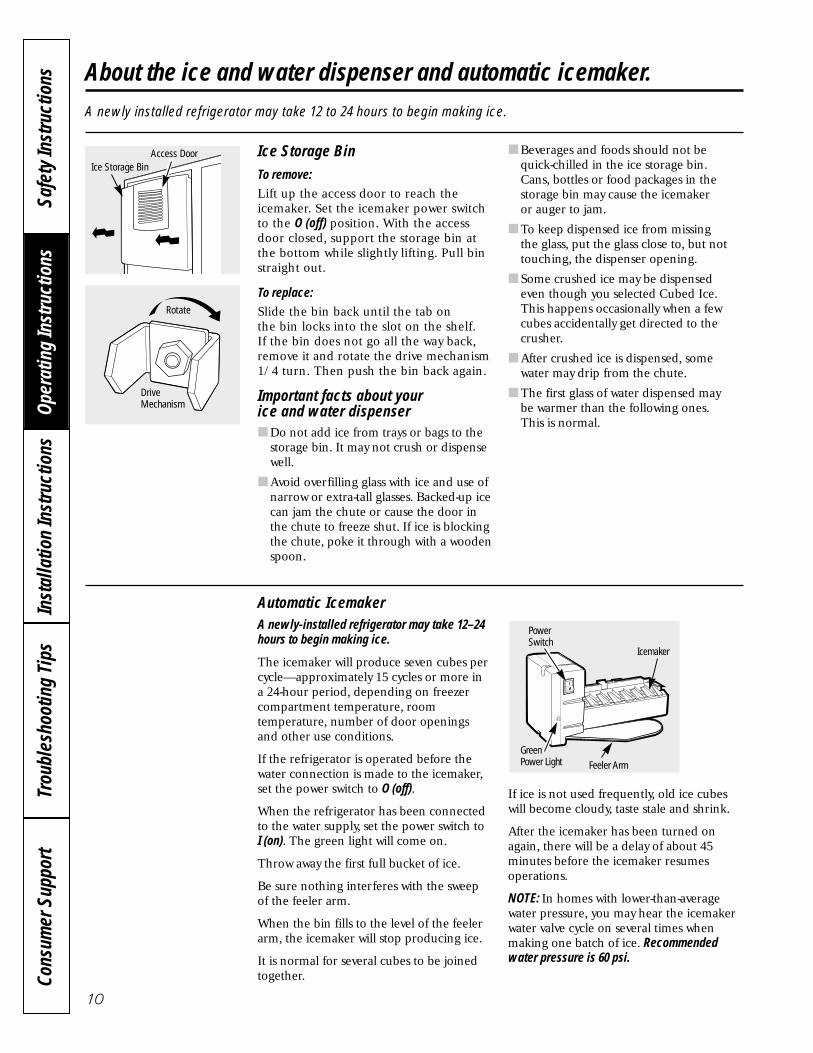
Ice Storage BinTo remove:Lift up the access door to reach theicemaker. Set the icemaker power switchto the O (off) position. With the accessdoor closed, support the storage bin atthe bottom while slightly lifting. Pull binstraight out.
To replace:Slide the bin back until the tab on the bin locks into the slot on the shelf. If the bin does not go all the way back,remove it and rotate the drive mechanism1/4 turn. Then push the bin back again.
Important facts about your ice and water dispenser■ Do not add ice from trays or bags to the
storage bin. It may not crush or dispensewell.
■ Avoid overfilling glass with ice and use ofnarrow or extra-tall glasses. Backed-up icecan jam the chute or cause the door inthe chute to freeze shut. If ice is blockingthe chute, poke it through with a woodenspoon.
■ Beverages and foods should not be quick-chilled in the ice storage bin. Cans, bottles or food packages in thestorage bin may cause the icemaker or auger to jam.
■ To keep dispensed ice from missing the glass, put the glass close to, but nottouching, the dispenser opening.
■ Some crushed ice may be dispensed even though you selected Cubed Ice.This happens occasionally when a fewcubes accidentally get directed to thecrusher.
■ After crushed ice is dispensed, somewater may drip from the chute.
■ The first glass of water dispensed may be warmer than the following ones. This is normal.
A newly installed refrigerator may take 12 to 24 hours to begin making ice.
Automatic IcemakerA newly-installed refrigerator may take 12–24hours to begin making ice.
The icemaker will produce seven cubes percycle—approximately 15 cycles or more in a 24-hour period, depending on freezercompartment temperature, roomtemperature, number of door openingsand other use conditions.
If the refrigerator is operated before thewater connection is made to the icemaker,set the power switch to O (off).
When the refrigerator has been connectedto the water supply, set the power switch to I (on). The green light will come on.
Throw away the first full bucket of ice.
Be sure nothing interferes with the sweepof the feeler arm.
When the bin fills to the level of the feelerarm, the icemaker will stop producing ice.
It is normal for several cubes to be joinedtogether.
If ice is not used frequently, old ice cubeswill become cloudy, taste stale and shrink.
After the icemaker has been turned onagain, there will be a delay of about 45minutes before the icemaker resumesoperations.
NOTE: In homes with lower-than-averagewater pressure, you may hear the icemakerwater valve cycle on several times whenmaking one batch of ice. Recommendedwater pressure is 60 psi.
Icemaker
Feeler Arm
PowerSwitch
GreenPower Light
Ice Storage BinAccess Door
Rotate
DriveMechanism

11
About the ice and water dispenser. ElectroluxUSA.com
To Use the Dispenser
Select Cubed Ice , Crushed Ice ,
or Water .
Press the glass gently against the middle of the dispenser pad.
The spill shelf is not self-draining. To reduce water spotting, the shelf and its grille should be cleaned regularly.
If no water is dispensed when therefrigerator is first installed, there may beair in the water line system. Press thedispenser arm for at least two minutes toremove trapped air from the water line and to fill the water system. To flush outimpurities in the water line, throw away the first six glassfuls of water.
CAUTION: Never put fingersor any other objects into the ice crusherdischarge opening.
Locking the DispenserPress the LOCK/LIGHTbutton for 3 seconds to lock the dispenserand control panel. Tounlock, press and holdthe button again for 3 seconds.
Dispenser LightThis button turns the night light on thedispenser on and off.The light also comes on when the dispenserpad is pressed. If thislight burns out, it shouldbe replaced with a 6 watt12V maximum bulb.
Express IceWhen you need ice in a hurry, press this button to speed up iceproduction. This willincrease ice productionfor the following 48 hours or until you press the button again.
Door AlarmTo turn the Door Alarmon, press the DOORALARM button once.The ACTIVE light willcome on. To turn it off,press it again. When theDOOR ALARM is active,the ACTIVE light willflash if you open thedoor and beep if youkeep the door open formore than 2 minutes.The light goes out andthe beeping stops whenyou close the door.
Spill Shelf
Consumer Support
Troubleshooting TipsOperating Instructions
Safety InstructionsInstallation Instructions

Cons
umer
Sup
port
Trou
bles
hoot
ing
Tips
Oper
atin
g In
stru
ctio
nsSa
fety
Inst
ruct
ions
Inst
alla
tion
Inst
ruct
ions
12
Cleaning the OutsideThe spill shelf and the area beneath it shouldbe cleaned periodically with a mild liquid dishdetergent.
Dispenser pad. Before cleaning, lock the dispenser by pressing the LOCK/LIGHTbutton for 3 seconds to prevent activatingthe dispenser. Clean with warm water and a mild liquid dish detergent. Rinsethoroughly and wipe dry. Unlock thedispenser by pressing the LOCK/LIGHTbutton for 3 seconds.
Door handles. Clean with a cloth dampenedwith soapy water. Dry with a soft cloth.
Keep the outside clean. Wipe with a cleancloth lightly dampened with mild liquiddish detergent. Dry with a clean, soft cloth.
Do not wipe the refrigerator with a soileddish cloth or wet towel. These may leave aresidue that can damage the finish. Do notuse scouring pads, powdered cleaners,bleach or cleaners containing bleachbecause these products can scratch anddamage the finish.
Stainless steel. Regularly clean and polish the Stainless Steel Doors with acommercially available stainless steelcleaner.
Do not use appliance wax or polish on the stainless steel.
Cleaning the InsideTurn off power at the circuit breaker or fusebox before cleaning. If this is not practical,wring excess moisture out of sponge orcloth when cleaning around switches, lightsor controls.
Use warm water and baking soda solution— about a tablespoon (15 ml) of baking sodato a quart (1 liter) of water. This bothcleans and neutralizes odors. Thoroughlyrinse and wipe dry.
Other parts of the refrigerator, including doorgaskets, snack pan and vegetable drawers,ice storage bin and all plastic parts, can becleaned the same way.
Do not wash the tray or any plasticrefrigerator parts in the dishwasher.
Avoid cleaning cold glass shelves with hotwater because the extreme temperaturedifference may cause them to break. Handleglass shelves carefully. Bumping temperedglass can cause it to shatter.
Dispenser drip area.
Care and cleaning of the refrigerator.

13
For long vacations or absences, removefood and unplug the refrigerator. Clean theinterior with a baking soda solution of onetablespoon (15 ml) of baking soda to onequart (1 liter) of water. Leave the doorsopen.
Set the icemaker power switch to the O (off)position and shut off the water supply to the refrigerator.
If the temperature can drop below freezing,have a qualified servicer drain the watersupply system to prevent serious propertydamage due to flooding.
ElectroluxUSA.com
Preparing for Vacation
Preparing to MoveSecure all loose items such as shelves anddrawers by taping them securely in place to prevent damage.
CAUTION: Due to the weightand size of this refrigerator, and to reduce therisk of personal injury or damage to theproduct, A MINIMUM OF 4 PEOPLE AREREQUIRED TO BRING THE UNIT INTO THEHOME AND 2 PEOPLE ARE REQUIRED FORPROPER INSTALLATION.
Be sure the refrigerator stays in an uprightposition during moving.
Consumer Support
Troubleshooting TipsOperating Instructions
Safety InstructionsInstallation Instructions

Cons
umer
Sup
port
Trou
bles
hoot
ing
Tips
Oper
atin
g In
stru
ctio
nsSa
fety
Inst
ruct
ions
Inst
alla
tion
Inst
ruct
ions
14
Replacing the light bulbs.Setting the controls to OFF does not remove power to the light circuit.
Refrigerator Compartment—Upper Light
Raise the grille panel, set the masterpower switch to the O (off) position andallow lamps to cool.
To remove the light shield, press on theLeft side of the shield and pull down.
Replace the bulbs with appliance bulbsof the same or lower wattage. Replacethe shield by engaging the bottom tabinto the slot and applying light forwardpressure until the shield snaps in place.
Set the master power switch to the I (on)position and close the grille panel.
Refrigerator Compartment—Lower LightThis light is located above the top drawer.
Raise the grille panel, set the masterpower switch to the O (off) position andallow lamps to cool.
Remove items from the shelf above thelight shield. Remove the shelf.
Use both hands to grasp each end ofthe light shield. Press in on the bottomof the shield with your thumbs whilerotating the cover up and out.
Replace the bulb with an appliancebulb of the same or lower wattage.Replace the shield by engaging the bottom tab into the slot and applyinglight forward pressure until the shieldsnaps in place.
Set the master power switch to the I (on)position and close the grille panel.
Freezer CompartmentRaise the grille panel, set the masterpower switch to the O (off) position andallow lamps to cool.
Remove the items from the shelf justbelow the light shield. Remove theshelf.
To remove the light shield, press downon the top of the shield and pull thetabs out of the slots. Tilt the shieldforward and out.
Replace the bulb with an appliancebulb of the same or lower wattage,and reinstall the light shield. Replacethe shield by engaging the bottom tabinto the slot and applying light forwardpressure until the shield snaps in place.
Set the master power switch to the I (on)position and close the grille panel.
DispenserRaise the grille panel, set the masterpower switch to the O (off) position andallow lamps to cool.
The bulb is located in the dispenserunder the control panel. Remove thetwo screws from the light shield. Slidethe light shield toward the dispenser todisengage the tabs, then remove thelight shield. Remove the light bulb byturning it counterclockwise.
Replace the bulb with a bulb of thesame size and wattage. Replace thelight shield by sliding the tabs intothe slots in the front of the dispenser.Replace the two screws.
Set the master power switch to the I (on)position and close the grille panel.
(appearance may vary)

Installation
Instructions
Built-In Side-By-SideRefrigerators
If you have questions, call 1-877-4ELECTROLUX 877-435-3287 or visit our website at:
BEFORE YOU BEGINRead these instructions completelyand carefully.
• IMPORTANT — Observe all governing codes and ordinances.
• Note to Installer – Be sure to leave theseinstructions for the consumer’s and localinspector’s use.
• Note to Consumer – Keep these instructionswith your Owner’s Manual for future reference.
• Skill Level – Installation of this refrigeratorrequires basic mechanical, carpentry andplumbing skills. Proper installation is theresponsibility of the installer. Product failuredue to improper installation is not coveredunder the Electrolux Home ProductsWarranty. See warranty information.
• Completion Time – 90 minutes (newinstallations require more time thanreplacement installations).
CAUTION:Due to the weight and size of this refrigerator,and to reduce the risk of personal injury ordamage to the product, A MINIMUM OF 4PEOPLE ARE REQUIRED TO BRING THE UNITINTO THE HOME AND 2 PEOPLE AREREQUIRED FOR PROPER INSTALLATION.
WARNING:• These refrigerators are top-heavy and must
be secured to prevent the possibility oftipping forward. Anti-Tip protection isrequired. See Step 4 on page 30 for details.
• Use this appliance only for its intended purpose.• Immediately repair or replace electric power
supply cords that become frayed or damaged.• Set the Master Power switch to the
O (OFF) position before cleaning or makingrepairs.
• Repairs should be made by a qualifiedservice technician.
For local service in your area, call1-877-4ELECTROLUX or 877-435-3287
For parts and accessories, call 1-877-4ELECTROLUX or 877-435-3287
READ CAREFULLY.KEEP THESE INSTRUCTIONS.
15

Installation Instructions
16
HARDWARE SUPPLIED• Anti-Tip brackets
Anti-Tip Brackets
MATERIALS REQUIRED• 36″ long, 2″ x 4″ wood block for Anti-Tip
bracket installation• #12 or #14 wood screws for Anti-Tip bracket• Screws to secure refrigerator to cabinets• 1/4″ O.D. copper water line tubing.• Water shutoff valve• Custom panels for doors and grille panel
(if installing custom panels)• Special 3M Dual Lock adhesive strips for
1/4″ side panels (if installing side panels)
36″ Wood Block 1/4″ O.D. Copper Water LineTubing
TOOLS REQUIRED• Tinsnips to cut banding• Stepladder• Bucket• Level• Appliance dolly• Tubing cutter• Flathead screwdriver• 1/2″ open-end wrench• #2 Phillips screwdriver• Drill and appropriate bits• 7/32″, 1/2″ sockets• Safety glasses• 7/16″ open-end wrench• Pliers
Appliance Dolly
Stepladder
Safety Glasses
Water Shutoff Valve #12 or #14 Wood Screws
Screws
Special 3M Dual Lock Adhesive Strips
Custom Panels
Sockets
Open-end Wrenches Bucket
Drill & Bits
Flathead Screwdriver
Tubing Cutter
Phillips HeadScrewdriver Level
Pliers
Tinsnips
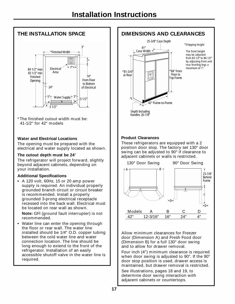
THE INSTALLATION SPACE
Water and Electrical Locations
The opening must be prepared with theelectrical and water supply located as shown.
The cutout depth must be 24″The refrigerator will project forward, slightlybeyond adjacent cabinets, depending onyour installation.
Additional Specifications
• A 120 volt, 60Hz, 15 or 20 amp powersupply is required. An individual properlygrounded branch circuit or circuit breakeris recommended. Install a properlygrounded 3-prong electrical receptaclerecessed into the back wall. Electrical mustbe located on rear wall as shown.Note: GFI (ground fault interrupter) is notrecommended.
• Water line can enter the opening throughthe floor or rear wall. The water lineinstalled should be 1/4″ O.D. copper tubingbetween the cold water line and waterconnection location. The line should belong enough to extend to the front of therefrigerator. Installation of an easilyaccessible shutoff valve in the water line isrequired.
DIMENSIONS AND CLEARANCES
Allow minimum clearances for Freezer door (Dimension A) and Fresh Food door(Dimension B) for a full 130° door swing and to allow for drawer removal.Four inch (4″) minimum clearance is requiredwhen door swing is adjusted to 90°. If the 90°door stop position is used, drawer access ismaintained, but drawer removal is restricted.See illustrations, pages 18 and 19, todetermine door swing interaction withadjacent cabinets or countertops.
*The finished cutout width must be:41-1/2″ for 42″ models
42" Frame-to-Frame
Depth IncludingHandles 26-7/8"
41" Case Width
25-3/8" Case Depth
*81-3/4"at Rear
*84" FromFloor to
Top Frame
*Finished Width
ElectricalArea
84 1/2" max83 1/2" min
FinishedOpening
74"From Floorto Bottom
of Electrical24"
5" 5"3 1/2"Water Supply
3 1/2"
3"
7"
7"
Product Clearances
These refrigerators are equipped with a 2position door stop. The factory set 130° doorswing can be adjusted to 90° if clearance toadjacent cabinets or walls is restricted.
130° Door Swing 90° Door SwingBA
23-7/8"BehindFrame
C
DD
Models A B C D42″ 12-3/16″ 16″ 24″ 4″
Installation Instructions
*Shipping height
The front height may be adjusted from 83-1/2" to 84-1/2"by adjusting front andrear leveling legs amaximum of 1".
17

1/2"
1"
3/4" Custom Panel(Nominal Size)
1/4"
1/2"
3/4"2"
1-1/4"
1-1/2"
1-3/4"3"
2-1/4"
2-1/2"
2-3/4"
1/4"
1/2"
3/4"
Fresh FoodDoor
Backer Panel
23-7/8" FromRear of
Refrigerator
1"
Refrigerator
CaseTrim
3/4"
1/4"
1"
Top View130° Door Swing(factory setting)Scale 1:1
Installation Instructions
18

1/2"
1/4"
1/2"
3/4"
1"
1-1/4"
1-1/2"
23-7/8"From Rear of Refrigerator
3/4" Custom Panel(Nominal Size)
Case Trim
Refrigerator
Fresh FoodDoor
Backer Panel
3/4"
1/4"
1"
Top View90° Door Swing(optional setting)Scale 1:1
Installation Instructions
19

CUSTOMIZATION BASICS:
Stainless Steel Wrapped Models
Stainless Steel Wrapped Refrigerators
Stainless Steel wrapped refrigerators havewrapped doors and grille panels, and bevelededges. These models are shipped ready forinstallation.
Trimmed Models
Trimmed Refrigerator Panels
Trimmed refrigerators are designed to becustomized with decorative panels. Fieldinstalled custom door and grille panels arerequired. There are three custom paneloptions. You can install a 1/4″ framed panel, a 3/4″ framed custom panel or a 3/4″ full-width overlay custom panel.
1/4″ Framed Panels
You may install 1/4″ thick custom panels fromyour cabinet manufacturer. The decorativepanel slides into the factory installed trim.
Door Handles On Trimmed RefrigeratorsThe handles can be used to accommodateboth framed or custom panels.NOTE: For 3/4″ custom panels, please refer to diagrams on page 23 for optimum handleclearance.
3/4″ Framed Custom Panels3/4″ framed custom panels are secured to a 1/4″ finished backer panel. They aredesigned to slide into the factory installedtrim, no kits required. The backer panel will be exposed on the handle side andtherefore must be finished.
3/4″ Full-Width Overlay Custom Panels3/4″ full-width overlay custom panels aredesigned to slide into the factory installedtrim, no kits required. In this design, youcan achieve a nearly trimless appearance. Aspacer panel must be installed between thefinished backer and appearance panel. Thebacker panel will be exposed on the handleside and therefore must be finished.
Door Handles
3/4" Custom Panel
3/4" Overlay Panel.10" Thick Spacer Panel
1/4" Thick Backer Panel
Framed Panel
Door Handles
Installation Instructions
20

1/4″ FRAMED PANEL DIMENSIONSIf you choose to install framed panels, theymust be cut to the dimensions shown. Thepanels will slide into the frame on the doorand grille.
IMPORTANT NOTE: Maximum weight for Fresh Food panel is 70 pounds and 30 pounds total for Freezer panels.
IMPORTANT NOTE: Dispenser Trim
The refrigerator is supplied with factory installeddispenser trim.• If panel is less than 1/4″ thick, a noticeable gap will be
created around the dispenser trim. Foam tape may beapplied on the door to improve the fit.
• If panel is more than 1/4″ thick, the panel will not fitbehind the trim.
ED
F
A
BGrille Panel
C
DispenserCutout
FreezerPanel
Fresh Food Panel
G
1/4"Panel
Door
5/16"Trim
Reveal
Front Panel Dimensions (in inches)
A B C D E F G
42″ Models 39-15/16 10-3/4 67-7/8 16-7/16 22-11/32 17-13/16 35-5/32
Installation Instructions
21

3/4″ FRAMED CUSTOM PANEL OPTIONFor a more custom appearance, 3/4″ framed custompanels may be installed on trimmed models. The overlaypanel is secured to a 1/4″ finished backer panel. Theassembled custom panel then slides into the trim withthe same procedure described on page 33.
3/4″ FULL-WIDTH OVERLAY CUSTOM PANEL OPTIONThis design provides a nearly trimless appearance. The fullwidth overlay panel covers most of the door trim. In this design,a spacer panel must be installed between the finished backerand overlay panel.
NOTE: Left-to-right offset is not equalto top-to-bottom offset.
NOTE: Left-to-right offset is not equalto top-to-bottom offset.
.250 + .750 = 1.000 Maximum Total Panel Thickness
IMPORTANT NOTE: Maximum total weight for anyassembled Fresh Food panel is 70 pounds and 30 pounds total for Freezer panels.
3/4"CustomOverlay Panel
1/4"BackerPanel
Door
3/4"
Overlay Panel
Backer Panel
Custom OverlayPanel
1/4"BackerPanel
Door
.10 InchSpacer
Installation Instructions
22
.250 + .10 + .750 = 1.100 Maximum Total Panel Thickness
Spacer Panel
Overlay Panel
Backer Panel

3/8"
3-1/8"
5/16"
1" Thick Max.or 3/4" Plus1/4" Backer
B
2-1/2"
3-1/8" Min.1/4" Max.
A
5/16"
Required for OptimalHandle Clearance
3/4″ FRAMED CUSTOM WOOD PANELSSecured to a 1/4″ finished backer panel. This designprovides a framed appearance.
Fresh Food Panel
Installation Instructions
23
42″ Models A B
1/4″ Backer Panel 22-5/16″ 67-7/8″3/4″ Overlay Panel 18-13/16″ 67-1/4″

2-1/2"
3-1/8" Min.1/4" Max.
Required for OptimalHandle Clearance
3/8"
3-1/8"1" Thick Max.or 3/4" Plus1/4" Backer
5/16"
A
5/16"B
3/8"
1" Thick Max.or 3/4" Plus1/4" Backer
5/16"
5/16"
3-1/8"
A
B
1" Thick Max.or 3/4" Plus1/4" Backer
5/16"
5/16"
1/4"
1/4"
A
B
3/4″ FRAMED CUSTOM WOOD PANELSSecured to a 1/4″ finished backer panel. This design provides a framed appearance.
Grille Panel
Upper Freezer Panel
Lower Freezer Panel
Installation Instructions
24
42″ Models A B
1/4″ Backer Panel 39-15/16″ 10-3/4″3/4″ Overlay Panel 39-7/16″ 10-1/8″
42″ Models A B
1/4″ Backer Panel 16-7/16″ 17-13/16″3/4″ Overlay Panel 12-15/16″ 17-3/16″
42″ Models A B
1/4″ Backer Panel 16-7/16″ 35-1/8″3/4″ Overlay Panel 12-15/16″ 34-1/2″

1/4"Max.
Required for OptimalHandle Clearance
3-1/8"
2-1/2"
3-1/8" Min.
B
A
3/4″ FULL-WIDTH OVERLAY CUSTOM PANELSThis panel design provides a nearly trimless appearance.
Assemble the spacerpanel onto the finishedbacker panel. Allow1/2″ clearance on thetop, bottom and hingeside. Allow 3-5/8″ onthe handle side. Securethe panels with glue.Be sure to observeclearances shown onall sides.Secure the overlaypanel to the assembledbacker/spacer panel.Use glue and screws.Countersink screwsinto the backer panel.
Installation Instructions
25
42″ Models A B
1/4″ Backer Panel 22-5/16″ 67-7/8″0.10″ Spacer Panel 18-3/16″ 66-7/8″3/4″ Overlay Panel 19-5/16″ 68-1/8″
3-5/8"
1/2"
1/2"
1/2"
Fresh Food Panel
Spacer Panel
Finished Backer Panel

3-1/8" Min.1/4" Max.
Required for OptimalHandle Clearance
3-1/8"
3-1/8"5/16"
5/16"
A
B
A
B
A
B
2-1/2"
3/4″ FULL-WIDTH OVERLAY CUSTOM PANELSThis panel design provides a nearly trimless appearance.Assemble the spacer panel onto the backer panel. Allow 1/2″ clearance on all four sides of thegrille spacer panel. Allow 1/2″ clearance on the top and hinge side, 15/16″ on the bottom and 3-5/8″on the handle side of the upper freezer door panel. Allow 15/16″ on the top, 1/2″ clearance on thebottom and hinge side and 3-5/8″ on the handle side of the lower freezer door panel. Secure thepanels with glue. Be sure to observe clearances on all sides.Secure the appearance panel to the assembled backer/spacer panel. Use glue and screws. Countersink screws into the backer panel.
Grille Panel
Lower Freezer Panel
Upper Freezer Panel
Installation Instructions
26
42″ Models A B
1/4″ Backer Panel 39-15/16″ 10-3/4″0.10″ Spacer Panel 38-15/16″ 9-3/4″3/4″ Overlay Panel 40-3/16″ 11″
42″ Models A B
1/4″ Backer Panel 16-7/16″ 35-1/8″0.10″ Spacer Panel 12-5/16″ 33-11/16″3/4″ Overlay Panel 13-7/16″ 34-15/16″
42″ Models A B
1/4″ Backer Panel 16-7/16″ 17-13/16″0.10″ Spacer Panel 12-5/16″ 16-3/8″3/4″ Overlay Panel 13-7/16″ 17-5/8″
3-5/8"
15/16"
1/2"
1/2"
Spacer Panel
Finished Backer Panel
3-5/8"
1/2"
15/16"
1/2"
Spacer Panel
Finished Backer Panel
Upper Freezer PanelSpacer Assembly
Lower Freezer PanelSpacer Assembly

GROUNDING THE REFRIGERATOR
IMPORTANT—Please read carefully
FOR PERSONAL SAFETY, THIS APPLIANCEMUST BE PROPERLY GROUNDED.
The power supply cord of this appliance isequipped with a three-prong (grounding)plug which mates with a standard three-prong (grounding) wall receptacle tominimize the possibility of electric shockhazard from this appliance.
Have the wall outlet and circuit checked by aqualified electrician to make sure the outlet isproperly grounded.
Where a standard 2-prong wall outlet is encountered, it is your personalresponsibility and obligation to have itreplaced with a properly grounded 3-prongwall outlet.
DO NOT, UNDER ANYCIRCUMSTANCES, CUT OR REMOVE THE THIRD (GROUND) PRONGFROM THE POWER CORD.
DO NOT USE AN ADAPTER PLUG TOCONNECT THE REFRIGERATOR TO A 2-PRONG OUTLET.
DO NOT USE AN EXTENSION CORD WITH THIS APPLIANCE.
SIDE PANELSSide panels (not supplied) must beused whenever the sides of therefrigerator will beexposed. The 1/4″side panels will slipinto the side casetrim. Order sidepanels from yourcabinet manufacturer.
*Depending oninstallation height.
FLOORINGFor proper installation, this refrigerator mustbe placed on a level surface of hard materialthat is at the same height as the rest of theflooring. This surface should be strongenough to support a fully loaded refrigerator,or approximately 1500 lb.NOTE: Protect the finish of the flooring. Cut alarge section of the cardboard carton and placeunder the refrigerator where you are working.
24"
*84"
*3" to 4"
1-1/2"
Installation Instructions
27

1 REMOVE PACKAGING
CAUTION: Refrigerator is Top-Heavy—be careful when moving. When using an appliance dolly, handle from Freezer side only.• Carefully cut banding at the top and
bottom; remove outer carton.• Slide out rear corner posts (2).• Slide carton off top of cabinet.
NOTE: DO NOT LAY CABINET DOWN IN ORDER TO REMOVE SKID!
• The unit is secured to the skid with six 7/16″ bolts and six 1/2″ nuts.
• Remove all six 7/16″ bolts that securemetal brackets to the refrigerator.
• Remove the three 1/2″ nuts and washersfrom the Freezer side.
• Remove nut from rear wood block on Freezer side.
• Tilt unit up on Freezer side toward FreshFood side.
• Push bolts down, remove metal bracketfrom Freezer side. Remove wood blockfrom Freezer side.
• Slide the appliance dolly underneath theFreezer side.
• Using corner posts (2 on front corners) to prevent damage, secure unit toappliance dolly.
NOTE: If corner posts are too long, cut theposts to a shorter length.
• Lift the unit off the skid with the appliancedolly.
• Remove toekick taped to the top of theunit.
• Set toekick aside for final installation.
CAUTION: DO NOT ATTEMPTTO ROLL OR DRAG UNTIL UNIT IS OFF SKID.
CAUTION: MAKE SURE THE WATER LINE IS CLEAR OF APPLIANCE DOLLY TO AVOID DAMAGE.
MetalBracket
1/2" Nuts
Bolts
Toekick Taped toTop of Unit
Installation Instructions
28

2 INSTALL WATER LINE• A cold water supply is required for
automatic icemaker operation. The waterpressure must be between 40 and 120 psi.
• Route 1/4″ O.D. copper tubing betweencold water line and the water connectionlocation.
• Tubing should be long enough to extendto the front of the refrigerator. Allowenough tubing to accommodate bendleading into the water line connection.
NOTE: Certain types of plastic may crack orrupture with age and cause water damage toyour home.Shut off the main water supply.
Turn on the nearest faucet long enough to purge all the water from the line.• Install a shutoff valve between the
icemaker water valve and cold water pipein a basement or cabinet. The shutoffvalve should be located where it will beeasily accessible.
NOTE: It is best to install the valve into avertical water pipe. If you install the valve intoa horizontal water pipe, make the connectionat the top or side to avoid drawing off anysediment from the water pipe.• Drill a 1/4″ hole in the water pipe.• Fasten the shutoff valve to the pipe with
pipe clamp.• Tighten the clamp screws until the
sealing washer begins to swell. Do notOVERTIGHTEN.
• Place a compression nut and ferrule(sleeve) for copper tubing onto the end of the tubing and connect it to the shutoffvalve. Make sure the tubing is fully insertedinto the valve and ferrule is tightened.
• Turn on the main water supply and flush debris. Run about a quart of waterthrough the tubing into a bucket. Shut off water supply at the shutoff valve.
NOTE: Saddle type shutoff valves areincluded in many water supply kits. Beforepurchasing, make sure a saddle type valvecomplies with your local plumbing codes.
Floor
Copper Tubing
Saddle TypeShutoff Valve
Compression Nut
Ferrule(Sleeve)
Outlet Valve
Packing Nut
NOTE: Commonwealth of MassachusettsPlumbing Codes 248CMR must be adheredto. Saddle valves are illegal and use is notpermitted in Massachusetts. Consult withyour licensed plumber.
Installation Instructions
29

3 INSTALL SIDE PANELSSKIP THIS STEP WHEN NOT USING SIDE PANELSIf you are using 1/4" side panels, they should beinserted into the case trim. Fasten the panels tothe refrigerator with the 3M Dual Lock adhesivestrips before setting refrigerator in place.
4A ALTERNATE ANTI-TIPPRECAUTIONS
SKIP THIS STEP WHEN USING ANTI-TIPBRACKETS
All Profile built-in refrigerators are Top-Heavy. They must be secured to prevent the possibilityof tipping forward. Use this alternative methodto secure the refrigerator whenever steel wallstuds are encountered.
• Adjust height of refrigerator to matchinstallation cutout opening 83-1/2″ to 84-1/2″. The refrigerator must be level andplumb with cabinets. The top case trim atthe front is 2-1/8″ higher than the rear andwill overlap upper cabinets or cabinet trim.
• Open grille panel to access the top case trim.• Use a 3/16″ bit to drill 4 evenly spaced
clearance holes through the metal top case trim.
• Use a 1/16″ bit to drill pilot holes throughthe metal clearance holes and into woodsoffit. The holes should be centered in thesoffit or a 3/4″ minimum wood brace. Thebrace spanning the enclosure must besecurely fastened to cabinets on both sides.
• Install four 1-1/2″ drywall screws into thepilot holes.
4 INSTALL ANTI-TIP BRACKETS
WARNING: The refrigerator is Top-Heavy and must be securedto prevent the possibility of tipping forward.• Cut a 2″ x 4″ wood block 36″ long,
and secure the block tothe mountingbracketsprovided,using #12 or#14 wood screws.
• Secure thebrackets withwood block to theback wall so that it is82″ (or the rear installation height) from thefinished floor. Use #12 or #14 wood screws.
• Screws must penetrate at least 1″ into verticalwall studs.
Install (4) 1-1/2" Drywall ScrewsThrough Trim and Into Soffit
or 3/4" Min. Wood Brace
Top Case TrimSide View
Top Case Trim
3/4"Min.
ANTI-TIPPRECAUTIONS
PositionedAnti-TipBracket
Wall Stud(BehindDrywall)
Wood ScrewsMounted into
VerticalWood Studs
36"
Installation Instructions
30
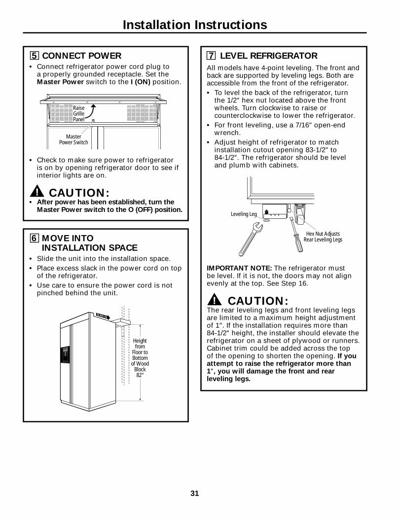
7 LEVEL REFRIGERATOR
All models have 4-point leveling. The front andback are supported by leveling legs. Both areaccessible from the front of the refrigerator.• To level the back of the refrigerator, turn
the 1/2″ hex nut located above the frontwheels. Turn clockwise to raise orcounterclockwise to lower the refrigerator.
• For front leveling, use a 7/16″ open-endwrench.
• Adjust height of refrigerator to matchinstallation cutout opening 83-1/2″ to 84-1/2″. The refrigerator should be level and plumb with cabinets.
IMPORTANT NOTE: The refrigerator must be level. If it is not, the doors may not alignevenly at the top. See Step 16.
CAUTION:The rear leveling legs and front leveling legsare limited to a maximum height adjustmentof 1″. If the installation requires more than 84-1/2″ height, the installer should elevate therefrigerator on a sheet of plywood or runners.Cabinet trim could be added across the top of the opening to shorten the opening. If youattempt to raise the refrigerator more than 1″, you will damage the front and rearleveling legs.
5 CONNECT POWER• Connect refrigerator power cord plug to
a properly grounded receptacle. Set theMaster Power switch to the I (ON) position.
• Check to make sure power to refrigerator is on by opening refrigerator door to see ifinterior lights are on.
CAUTION:• After power has been established, turn the
Master Power switch to the O (OFF) position.
6 MOVE INTO INSTALLATION SPACE
• Slide the unit into the installation space.• Place excess slack in the power cord on top
of the refrigerator.• Use care to ensure the power cord is not
pinched behind the unit.
RaiseGrillePanel
MasterPower Switch
Hex Nut AdjustsRear Leveling Legs
Leveling Leg
Heightfrom
Floor toBottom
of WoodBlock82"
Installation Instructions
31

10 INSTALL GRILLE PANEL• Raise the grille panel to the stop position.
• Remove 4 screws on bottom trim; retain all screws.
• Remove bottom trim.• NOTE: Stainless steel and acrylic panels
are covered with a protective film. Removethe film before installing the panel.
• Slide panel over the metal backer paneland under the trim.
• If necessary, tap with a wood block untilpanel slips under the top trim piece.
• Reassemble bottom trim. Tighten screws.
RaiseGrillePanel
8 SECURE REFRIGERATOR TO CABINETS
Whenever possible, perform this step for anti-tip security. The refrigerator must be secured to preventtipping.
• Raise the grille panel to access case trim.• Drive a screw through the trim and into the
adjacent cabinet using holes provided.• Follow the same procedure on the opposite
side.
Drive ScrewsThrough Case Trim Into
Adjacent Cabinets
Raise Grille Panelto Stop Position
9 ADJUST DOOR SWINGNOTE: This refrigerator has a 2-position doorstop. When space does not allow the door toswing open fully to 130°, you may change thedoor swing to a 90° opening. SKIP THIS STEP IF DOOR OPENING ISSATISFACTORY FOR YOUR INSTALLATIONSITUATION.
• Open the door to view the bottom hinge.Note the door stop pin location. The pin isfactory installed in the 130° position.
• Partially close the door. From above, use aflat-head screwdriver to unscrew the doorstop pin and reinstall into the 90° position.
90°
130°
Hinge
DoorInterior
Installation Instructions
32
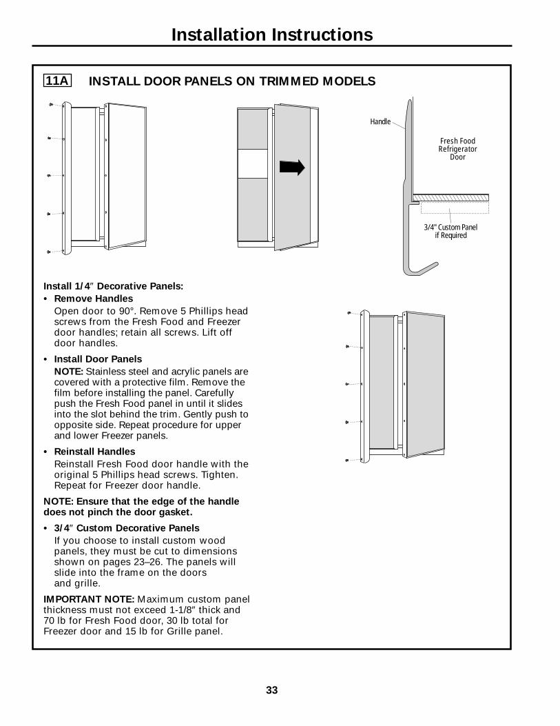
11A
Install 1/4″ Decorative Panels:
• Remove Handles
Open door to 90°. Remove 5 Phillips headscrews from the Fresh Food and Freezerdoor handles; retain all screws. Lift offdoor handles.
• Install Door Panels
NOTE: Stainless steel and acrylic panels arecovered with a protective film. Remove thefilm before installing the panel. Carefullypush the Fresh Food panel in until it slidesinto the slot behind the trim. Gently push toopposite side. Repeat procedure for upperand lower Freezer panels.
• Reinstall Handles
Reinstall Fresh Food door handle with theoriginal 5 Phillips head screws. Tighten.Repeat for Freezer door handle.
NOTE: Ensure that the edge of the handledoes not pinch the door gasket.
• 3/4″ Custom Decorative Panels
If you choose to install custom woodpanels, they must be cut to dimensionsshown on pages 23–26. The panels willslide into the frame on the doors and grille.
IMPORTANT NOTE: Maximum custom panelthickness must not exceed 1-1/8″ thick and70 lb for Fresh Food door, 30 lb total forFreezer door and 15 lb for Grille panel.
Fresh FoodRefrigerator
Door
Handle
3/4" Custom Panelif Required
Installation Instructions
33
INSTALL DOOR PANELS ON TRIMMED MODELS

11B
1. Remove handles from cartoning and any other protective packaging.
2. Place handle over pre-installed shoulder bolts (A) that are fastened into door in four locations.
3. While supporting handle and looking at upper end cap, fasten top-most allen set screw (B) with
supplied allen wrench, then fasten bottom allen set screw (C). See Figure 1.
4. Repeat Step 3 with bottom end cap using allen set screws (D and E), once upper section of handle is firmly secured to door. See Figure 2.
5. All set screws should be tightened and sub-flush (allen set screw should be buried just below the surface of the end cap) of handle end cap. The end caps should be drawn tight to freezer and refrigerator doors with no gaps.
Installation Instructions
34
INSTALL DOOR HANDLES ON STAINLESS STEEL MODELS
A A B
C
A A D
E
Figure 1Upper End Cap
Figure 2Bottom End Cap

13 TURN ON THE POWER• Set the Master Power switch to the I (ON)
position.• Check to make sure power to refrigerator is
on by opening refrigerator door to see ifinterior lights are on.
• The temperature controls are preset at 37°for the Fresh Food section and 0° for theFreezer section.
• Allow 24 hours to stabilize before makingadjustments.
• Dispense water for 2 minutes to removetrapped air from the water system.
RaiseGrillePanel
MasterPower Switch
12 CONNECT WATER SUPPLYCheck to make sure that Master Powerswitch is in the O (OFF) position.
• Locate and bring tubing to the front of thecabinet.
• Turn the water on to flush debris from line.Run about a quart of water through tubinginto a bucket, then shut off water.
Copper Tubing
• Slip a 1/4″ nut and ferrule onto end ofcopper tubing. Insert tube into the unionfitting on the unit and tighten nut to union.
• Turn on the water to check for leaks.
Note: Make sure excess tubing length doesnot interfere with toekick installation.
RefrigeratorWater Supply
HouseWater Supply
Installation Instructions
35

16 DOOR ALIGNMENT• Stand back from the refrigerator to inspect
the door alignment.• Shipping or the addition of heavy door
panels may have caused the doors to moveslightly out of alignment.
• If necessary, the Fresh Food door may be adjusted up or down to align with theFreezer door.
• Loosen the leveling mechanism.• Use a 7/32″ wrench to adjust the hinge pin
as shown.• Tighten the leveling mechanism.IMPORTANT NOTE: After the unit has beenleveled, if the fresh food door is higher thanthe freezer door, adjust the front right levelingleg lower to align the doors and, if required,raise the left leveling leg to level the unit sideto side.
14 START ICEMAKER
• Flip the switch to I (ON). The icemaker willbegin operation automatically.
• Make sure nothing interferes with thesweep of the feeler arm.
• Discard the first full bucket of ice cubes.• To turn the icemaker off, set the switch to
O (OFF).
15 INSTALL TOEKICK• Locate the supplied toekick (shipped taped
to the top of the refrigerator). Install with 2 screws provided.
• The vented toekick must remain unobstructedfor proper air flow.
Power Switch
Green Power Light
Feeler Arm
Bushing
Door Hinge
Case Hinge
7/32" WrenchRaise
Clockwise
Installation Instructions
36

37
Normal operating sounds.Newer refrigerators sound different from older refrigerators.Modern refrigerators have more features and use newertechnology.
HUMMM...WHOOSH...
■ The new high efficiency compressor may run fasterand longer than your old refrigerator and you mayhear a high-pitched hum or pulsating sound while it is operating.
■ You may hear a whooshing sound when the doorsclose. This is due to pressure equalizing within the refrigerator.
■ You may hear the fans spinning at high speeds. This happens when the refrigerator is first pluggedin, when the doors are opened frequently or when a large amount of food is added to the refrigeratoror freezer compartments. The fans are helping tomaintain the correct temperatures.
■ If either door is open for over 3 minutes, you mayhear the fans come on in order to cool the lightbulbs.
■ The fans change speeds in order to provide optimalcooling and energy savings.
CLICKS, POPS,CRACKS and CHIRPS
■ You may hear cracking or popping sounds when therefrigerator is first plugged in. This happens as therefrigerator cools to the correct temperature.
■ The compressor may cause a clicking or chirpingsound when attempting to restart (this could take up to 5 minutes).
■ The electronic control board may cause a clickingsound when relays activate to control refrigeratorcomponents.
■ Expansion and contraction of cooling coils duringand after defrost can cause a cracking or poppingsound.
■ After an icemaking cycle, you may hear the ice cubesdropping into the ice bucket.
WATER SOUNDS
■ The flow of refrigerant through the freezer coolingcoils may make a gurgling noise like boiling water.
■ Water dropping on the defrost heater can cause asizzling, popping or buzzing sound during thedefrost cycle.
■ A water dripping noise may occur during the defrostcycle as ice melts from the evaporator and flows intothe drain pan.
■ Closing the door may cause a gurgling sound due topressure equalization.
Do you hear what I hear? These sounds are normal.
For additional information on normalicemaker and dispenser operating sounds,see the About the automatic icemakerand About the ice and water dispensersections. Consum
er SupportTroubleshooting Tips
Operating InstructionsSafety Instructions
Installation Instructions

Cons
umer
Sup
port
Trou
bles
hoot
ing
Tips
Oper
atin
g In
stru
ctio
nsSa
fety
Inst
ruct
ions
Inst
alla
tion
Inst
ruct
ions
Troubleshooting tips… ElectroluxUSA.com
Troubleshooting Tips Save time and money! Review the charts on the followingpages first and you may not need to call for service.
Problem Possible Causes What To Do
Refrigerator does not Refrigerator in defrost cycle. • Wait about 30 minutes for defrost cycle to end.operate
Master power control set to OFF. • Set the control to an on setting.
Refrigerator is unplugged. • Push the plug completely into the outlet.
The fuse is blown/circuit •Replace fuse or reset the breaker.breaker is tripped.
The refrigerator is in •Unplug the refrigerator and plug it back in.showroom mode.
Vibration or rattling Refrigerator is not level. •See Level refrigerator.(slight vibration •See Door alignment.is normal)
Motor operates for Normal when refrigerator • Wait 24 hours for the refrigerator to completely long periods or cycles is first plugged in. cool down.on and off frequently.
Often occurs when large • This is normal.(Modern refrigeratorsamounts of food arewith more storageplaced in refrigerator.space and a largerDoor left open. • Check to see if package is holding door open.freezer require more
Hot weather or frequent • This is normal.operating time. They
door openings.start and stop often
Temperature controls • See About the temperature controls.to maintain even
set at the coldest temperatures.)
setting.
Refrigerator or freezer Temperature control not set • See About the temperature controls.compartment too warm cold enough.
Warm weather or frequent • Set the temperature control one step colder. door openings. See About the temperature controls.
Door left open. •Check to see if package is holding door open.
Frost or ice crystals Door left open. • Check to see if package is holding door open.on frozen food Too frequent or too long (frost within package door openings.is normal)
Divider between Automatic energy saver •This helps prevent condensation on the outside.refrigerator and freezer system circulates warm compartments liquid around front edge feels warm of freezer compartment.
Automatic icemaker Icemaker power switch • Set the power switch to the on position.does not work is in the off position.
Water supply turned off or • See Install water line.not connected.
Freezer compartment • Wait 24 hours for the refrigerator to completelytoo warm. cool down.
Piled up cubes in the storage •Level cubes by hand.bin cause the icemaker to shut off.
Ice cubes stuck in icemaker. • Turn off the icemaker, remove cubes and turn the(Green power light on icemaker back on.icemaker blinking).38

Troubleshooting tips…
Problem Possible Causes What To DoFrequent “buzzing” sound Icemaker power switch is in the • Set the power switch to the O (off) position. Keeping it
I (on) position, but the water supply in the I (on) position will damage the water valve.to the refrigerator has not been connected.
Ice cubes have odor/taste Ice storage bin needs cleaning. • Empty and wash bin. Discard old cubes.
Food transmitting odor/taste • Wrap foods well.to ice cubes.
Interior of refrigerator • See Care and cleaning.needs cleaning.
Small or hollow cubes Water filter clogged. • Replace filter cartridge with new cartridge or with plug.
Slow ice cube freezing Door left open. • Check to see if package is holding door open.
Temperature control not set • See About the temperature controls.cold enough.
Cube dispenser does not work Icemaker turned off or • Turn on icemaker or water supply.water supply turned off.
An item is blocking or has fallen into • Remove any item that might be blocking, or has fallen into, the ice chute inside the top door the chute.bin of the freezer.
Ice cubes are frozen to • Remove cubes.icemaker feeler arm.
Irregular ice clumps in • Break up with fingertip pressure and discard remaining clumps.storage container. • Freezer may be too warm. Adjust the freezer control to a
colder setting, one position at a time, until clumps do not form.
Dispenser is LOCKED. • Press and hold the LOCK button for 3 seconds.
Water has poor taste/odor Water dispenser has not been • Dispense water until all water in system is replenished.used for a long time.
Water in first glass is warm Normal when refrigerator • Wait 24 hours for the refrigerator to completely cool down.is first installed.
Water dispenser has not been • Dispense water until all water in system is replenished.used for a long time.
Water system has been drained. • Allow several hours for replenished supply to chill.
Water dispenser does Water supply line turned • See Install water line.not work off or not connected.
Water filter clogged. • Replace filter cartridge or remove filter and install plug.
Air may be trapped in the water system. • Press the dispenser arm for at least two minutes.
Dispenser is LOCKED. • Press and hold the LOCK button for 3 seconds.
Refrigerator control setting is too cold. • Set to a warmer setting.
Water spurting from Newly-installed filter cartridge. • Run water from the dispenser for 3 minutes (aboutdispenser one and a half gallons).
Water is not dispensed Water in reservoir is frozen. • Call for service.but icemaker is working
Refrigerator control setting is too cold. • Set to a warmer setting.
No water or ice cube production Supply line or shutoff valve is clogged. • Call a plumber.
Water filter clogged. • Replace filter cartridge or remove filter and install plug.
Dispenser is LOCKED. • Press and hold the LOCK button for 3 seconds.
CUBED was selected but Last setting was CRUSHED. • A few cubes were left in the crusher from the previousCRUSHED was dispensed setting. This is normal.
39
Consumer Support
Troubleshooting TipsOperating Instructions
Safety InstructionsInstallation Instructions

ElectroluxUSA.com
40
Problem Possible Causes What To Do
Orange glow in Defrost heater is on. •This is normal.the freezer
Refrigerator has odor Foods transmitting •Foods with strong odors should be tightly wrapped.odor to refrigerator. •Keep an open box of baking soda in the refrigerator;
replace every three months.
Interior needs cleaning. • See Care and cleaning.
Door not closing properly Door gasket on hinge side •Apply paraffin wax to the face of the gasket.sticking or folding over.
A door bin is hitting a shelf • Move the door bin up one position.inside the refrigerator.
Refrigerator is not level. • See Level refrigerator.• See Door alignment.
Moisture forms on Not unusual during •Wipe surface dry. outside of refrigerator periods of high humidity.
Moisture collects inside Too frequent or too(in humid weather, air long door openings.carries moisture intorefrigerator when doors are opened)
Interior light does No power at outlet. • Replace fuse or reset the breaker.not work Light bulb burned out. •See Replacing the light bulbs.
Water on kitchen floor or Cubes jammed in chute. • Poke ice through with a wooden spoon.on bottom of freezer
Hot air from top Normal air flow cooling motor. of refrigerator In the refrigeration process, it is
normal that heat be expelled in the area above the refrigerator.
Refrigerator never Adaptive defrost keeps • This is normal. The refrigerator will cycle off after theshuts off, but the compressor running during door remains closed for 2 hours.temperatures are OK door openings.
Refrigerator beeping Door open. • Close door.
Actual temperature not Unit just plugged in. • Allow 24 hours for system to stabilize.equal to Set temperature
Door open for too long. • Allow 24 hours for system to stabilize.
Warm food added to refrigerator. • Allow 24 hours for system to stabilize.
Defrost cycle is in process. • Allow 24 hours for system to stabilize.
Cons
umer
Sup
port
Trou
bles
hoot
ing
Tips
Oper
atin
g In
stru
ctio
nsSa
fety
Inst
ruct
ions
Inst
alla
tion
Inst
ruct
ions

Warranty Information ElectroluxUSA.com
41
Consumer Support
Troubleshooting TipsOperating Instructions
Safety InstructionsInstallation Instructions

42

State of California Department of Health Services
Water Treatment Device
Certificate Number
01 - 1474
Date Issued: April 25, 2001
Replacement ElementsFrigidaire PureSource 2 NGFC-2000 FC-100 Gibson Cool and Clean NGFC-2000 FC-100 Electrolux pure advantage NGFC-2000 FC-100
Manufacturer: Electrolux Home Products
The water treatment device(s) listed on this certificate have met the testing requirements pursuant to Section 116830 of the Health and Safety Code for the following health related contaminants:
Microbiological Contaminants and Turbidity Inorganic/Radiological ContaminantsCysts (protozoan) Lead Turbidity Mercury
Organic Contaminants Alachlor Atrazine Lindane 2,4-D Toxaphene
Rated Service Capacity: 400 gallons Rated Service Flow: 0.5 gpm
Do not use where water is microbiologically unsafe or with water of unknown quality, except that systems claiming cyst reduction may be used on water containing cysts.
Trademark/Model Designation
43

44
MEMO