Embed Size (px)
Citation preview
Refrigerator Service Manual
TRF-275W
TCL Home Appliances (HeFei) Co., Ltd.
Contents
1.Product introduction, Technical Parameters
2.Exploded View of Product Structure
3.Product operation rules
4.Refrigeration system and electrical control
5.Maintenance guide
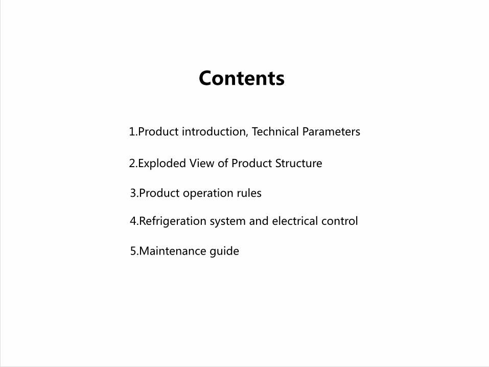
Product appearance structure and name of each part
1.Product introduction
Product front Front opening Product back

Product appearance structure and name of each part
Compressor compartment Display panel

TRF-275W is an air-cooled double door computer temperature controlled refrigerator, the upper part of
which is the refrigerating chamber, and the lower part is the freezer chamber.
The appearance modeling drawing is as follows:
Refrigerating light
Refrigerating shelf
Fruit and vegetable box cover
Fruit and vegetable box
Freezer drawer
Refrigerating door bottle holder
Door of refrigerating chamber
Door of freezer chamber
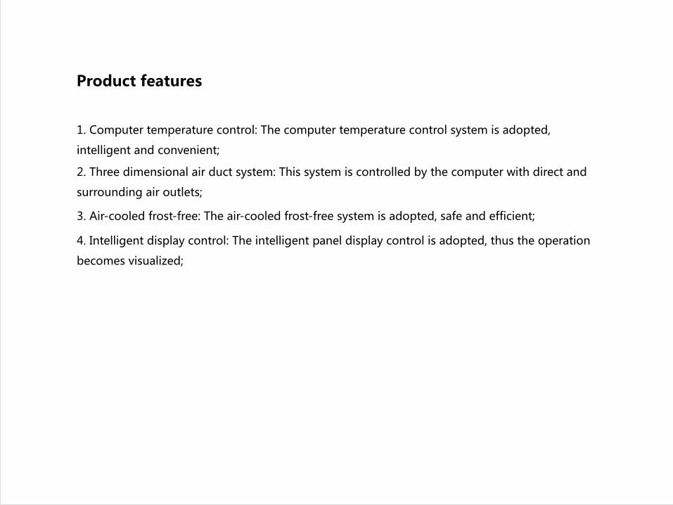
Product features
1. Computer temperature control: The computer temperature control system is adopted,
intelligent and convenient;
2. Three dimensional air duct system: This system is controlled by the computer with direct and
surrounding air outlets;
3. Air-cooled frost-free: The air-cooled frost-free system is adopted, safe and efficient;
4. Intelligent display control: The intelligent panel display control is adopted, thus the operation
becomes visualized;
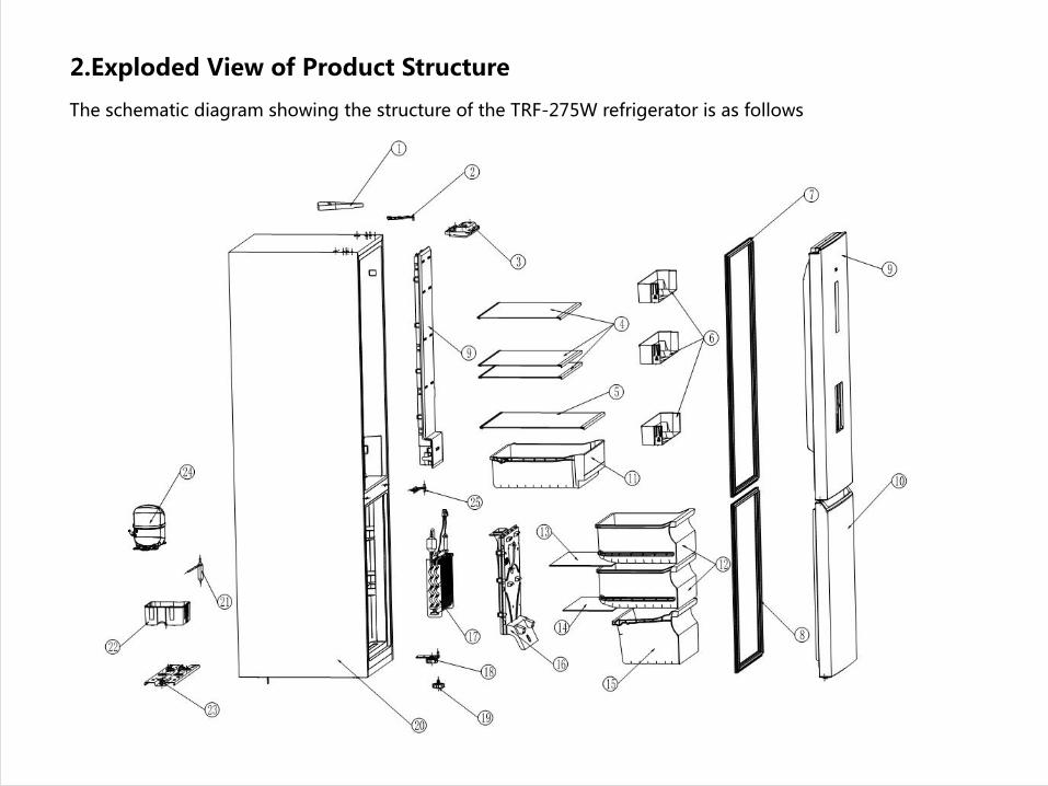
The schematic diagram showing the structure of the TRF-275W refrigerator is as follows
2.Exploded View of Product Structure
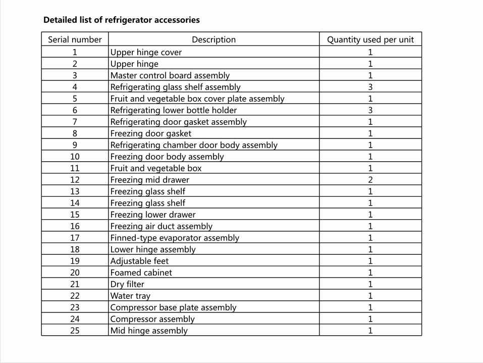
Detailed list of refrigerator accessories
Serial number Description Quantity used per unit1 Upper hinge cover 12 Upper hinge 13 Master control board assembly 14 Refrigerating glass shelf assembly 35 Fruit and vegetable box cover plate assembly 16 Refrigerating lower bottle holder 37 Refrigerating door gasket assembly 18 Freezing door gasket 19 Refrigerating chamber door body assembly 110 Freezing door body assembly 111 Fruit and vegetable box 112 Freezing mid drawer 213 Freezing glass shelf 114 Freezing glass shelf 115 Freezing lower drawer 116 Freezing air duct assembly 117 Finned-type evaporator assembly 118 Lower hinge assembly 119 Adjustable feet 120 Foamed cabinet 121 Dry filter 122 Water tray 123 Compressor base plate assembly 124 Compressor assembly 125 Mid hinge assembly 1
3. Product operation rules
I. The refrigerator will operate at 5℃ when it is powered on for the first time.
II. Manual temperature regulation function
1) Regulation of temperature inside the refrigerating chamber
Press or to regulate the temperature inside the refrigerating chamber. Each time you press the key, the
temperature will increase or decrease by 1℃. The temperature inside the refrigerating chamber will cycle
between "02" - "04" - "05" - "06" - "08" - "02". After selecting the appropriate temperature, stop the key
operation and wait for 5 seconds, then the set temperature will stop flashing and be confirmed.
III. Power off memory
When power goes off, the instantaneous working state at the time of power off will be locked. After power
on, it will still work according to the setting before power off.

Operating instructions for 275W series products (external display)
Figure 1 (Internal Display) Schematic
Diagram of Display Panel and Keys
The refrigerating chamber will run at 5℃ when it is
powered on for the first time.
Child lock function
When there is no key operation on the display panel
within 30 seconds, the display screen will go out and the
child lock function will automatically start. In this state,
any key can be pressed to wake up the display screen and
make it light up. Keep pressing the "Temperature control
switch" key for 3 seconds to unlock the keyboard.
Regulation of temperature inside the refrigerating
chamber
In the unlocked state, press the "Temperature control
switch" key to regulate the temperature inside the
refrigerating chamber. The temperature inside the
refrigerating chamber will cycle between "02" - "04" -"05"-
"06" - "08" - "Power cool" - "Smart" - "Energy saving" -
"02". After selecting the appropriate temperature, stop the
key operation and wait for 5 seconds, then the set
temperature will stop flashing and be confirmed.
Temperature display
Temperature
of 2℃
Temperature
of 5℃
Temperature
of 6℃Child lock
functionDoor opening
reminder
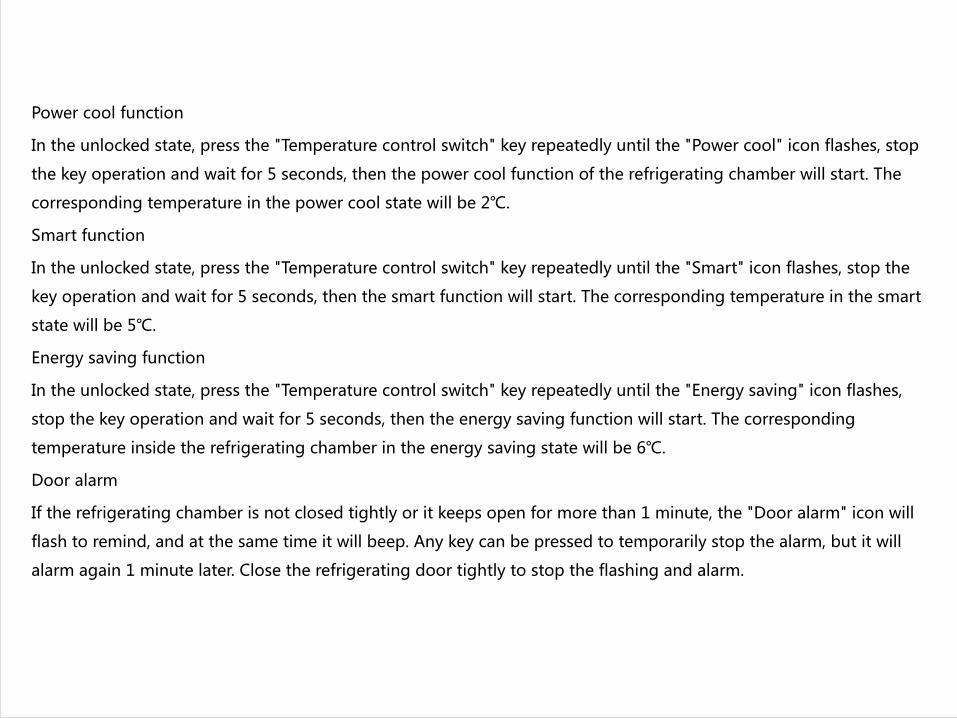
Power cool function
In the unlocked state, press the "Temperature control switch" key repeatedly until the "Power cool" icon flashes, stop
the key operation and wait for 5 seconds, then the power cool function of the refrigerating chamber will start. The
corresponding temperature in the power cool state will be 2℃.
Smart function
In the unlocked state, press the "Temperature control switch" key repeatedly until the "Smart" icon flashes, stop the
key operation and wait for 5 seconds, then the smart function will start. The corresponding temperature in the smart
state will be 5℃.
Energy saving function
In the unlocked state, press the "Temperature control switch" key repeatedly until the "Energy saving" icon flashes,
stop the key operation and wait for 5 seconds, then the energy saving function will start. The corresponding
temperature inside the refrigerating chamber in the energy saving state will be 6℃.
Door alarm
If the refrigerating chamber is not closed tightly or it keeps open for more than 1 minute, the "Door alarm" icon will
flash to remind, and at the same time it will beep. Any key can be pressed to temporarily stop the alarm, but it will
alarm again 1 minute later. Close the refrigerating door tightly to stop the flashing and alarm.
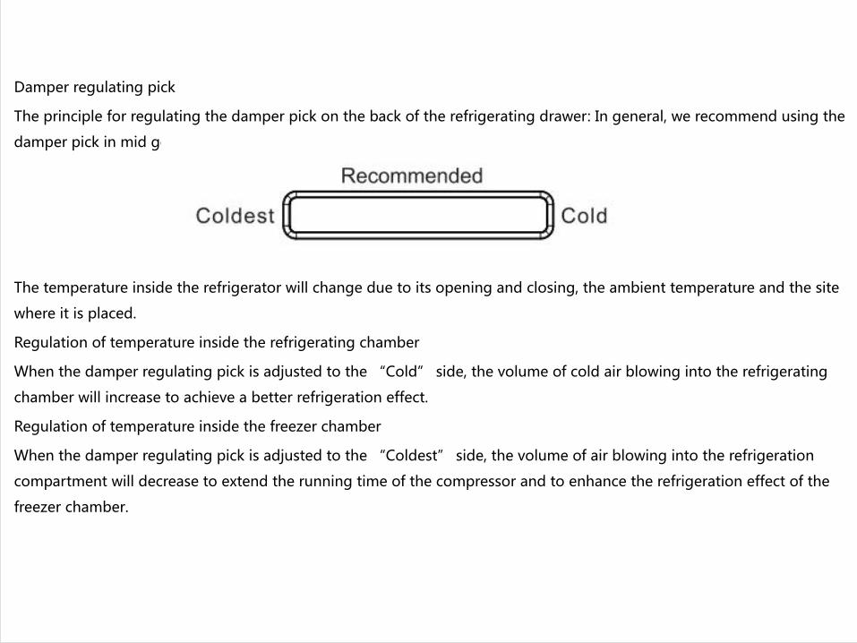
Damper regulating pick
The principle for regulating the damper pick on the back of the refrigerating drawer: In general, we recommend using the
damper pick in mid gear.。
The temperature inside the refrigerator will change due to its opening and closing, the ambient temperature and the site
where it is placed.
Regulation of temperature inside the refrigerating chamber
When the damper regulating pick is adjusted to the “Cold” side, the volume of cold air blowing into the refrigerating
chamber will increase to achieve a better refrigeration effect.
Regulation of temperature inside the freezer chamber
When the damper regulating pick is adjusted to the “Coldest” side, the volume of air blowing into the refrigeration
compartment will decrease to extend the running time of the compressor and to enhance the refrigeration effect of the
freezer chamber.
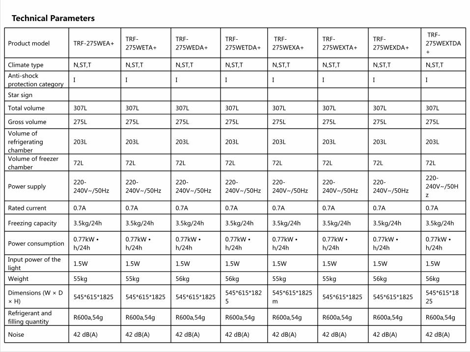
Technical Parameters
Product model TRF-275WEA+ TRF-275WETA+
TRF-275WEDA+
TRF-275WETDA+
TRF-275WEXA+
TRF-275WEXTA+
TRF-275WEXDA+
TRF-275WEXTDA+
Climate type N,ST,T N,ST,T N,ST,T N,ST,T N,ST,T N,ST,T N,ST,T N,ST,T
Anti-shock protection category
I I I I I I I I
Star sign
Total volume 307L 307L 307L 307L 307L 307L 307L 307L
Gross volume 275L 275L 275L 275L 275L 275L 275L 275L
Volume of refrigerating chamber
203L 203L 203L 203L 203L 203L 203L 203L
Volume of freezer chamber
72L 72L 72L 72L 72L 72L 72L 72L
Power supply 220-240V~/50Hz
220-240V~/50Hz
220-240V~/50Hz
220-240V~/50Hz
220-240V~/50Hz
220-240V~/50Hz
220-240V~/50Hz
220-240V~/50Hz
Rated current 0.7A 0.7A 0.7A 0.7A 0.7A 0.7A 0.7A 0.7A
Freezing capacity 3.5kg/24h 3.5kg/24h 3.5kg/24h 3.5kg/24h 3.5kg/24h 3.5kg/24h 3.5kg/24h 3.5kg/24h
Power consumption 0.77kW • h/24h
0.77kW • h/24h
0.77kW • h/24h
0.77kW • h/24h
0.77kW • h/24h
0.77kW • h/24h
0.77kW • h/24h
0.77kW • h/24h
Input power of the light
1.5W 1.5W 1.5W 1.5W 1.5W 1.5W 1.5W 1.5W
Weight 55kg 55kg 56kg 56kg 55kg 55kg 56kg 56kg
Dimensions (W × D × H)
545*615*1825 545*615*1825 545*615*1825545*615*1825
545*615*1825m
545*615*1825 545*615*1825545*615*1825
Refrigerant and filling quantity
R600a,54g R600a,54g R600a,54g R600a,54g R600a,54g R600a,54g R600a,54g R600a,54g
Noise 42 dB(A) 42 dB(A) 42 dB(A) 42 dB(A) 42 dB(A) 42 dB(A) 42 dB(A) 42 dB(A)
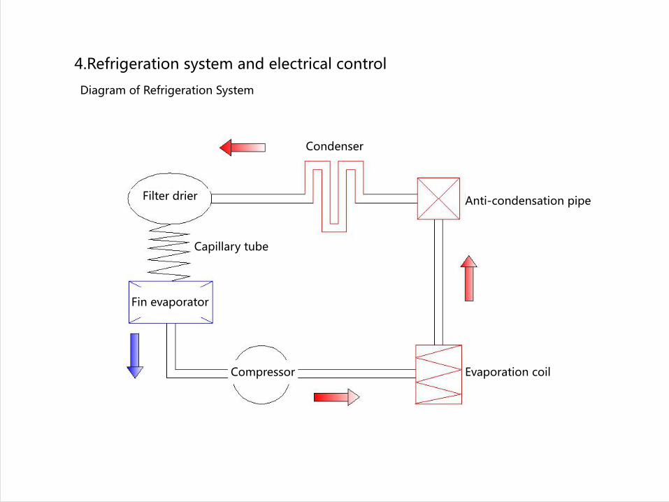
4.Refrigeration system and electrical control
Compressor
Filter drier
Capillary tube
Condenser
Anti-condensation pipe
Fin evaporator
Evaporation coil
Diagram of Refrigeration System
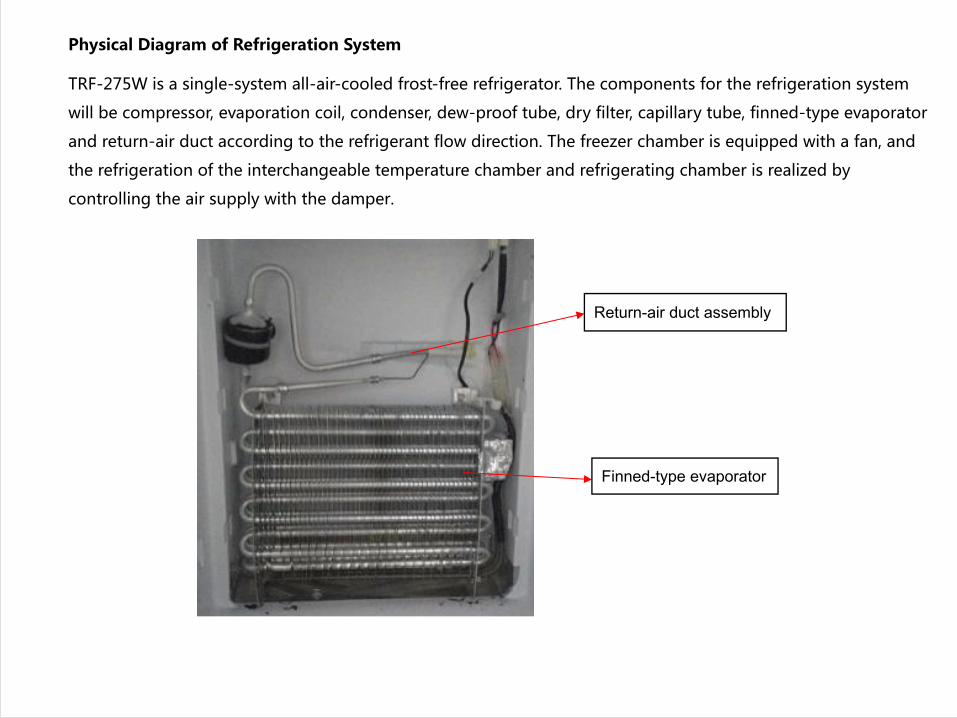
Physical Diagram of Refrigeration System
TRF-275W is a single-system all-air-cooled frost-free refrigerator. The components for the refrigeration system
will be compressor, evaporation coil, condenser, dew-proof tube, dry filter, capillary tube, finned-type evaporator
and return-air duct according to the refrigerant flow direction. The freezer chamber is equipped with a fan, and
the refrigeration of the interchangeable temperature chamber and refrigerating chamber is realized by
controlling the air supply with the damper.
Return-air duct assembly
Finned-type evaporator
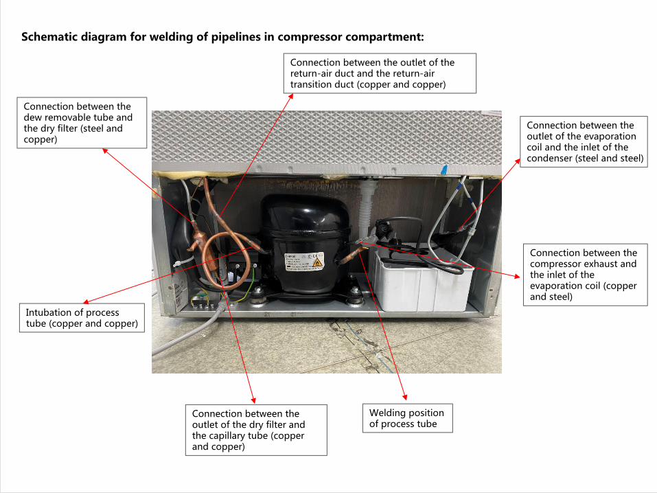
Schematic diagram for welding of pipelines in compressor compartment:
Intubation of process tube (copper and copper)
Connection between the outlet of the dry filter and the capillary tube (copper and copper)
Connection between the dew removable tube and the dry filter (steel and copper)
Connection between the outlet of the return-air duct and the return-air transition duct (copper and copper)
Connection between the outlet of the evaporation coil and the inlet of the condenser (steel and steel)
Connection between the compressor exhaust and the inlet of the evaporation coil (copper and steel)
Welding position of process tube
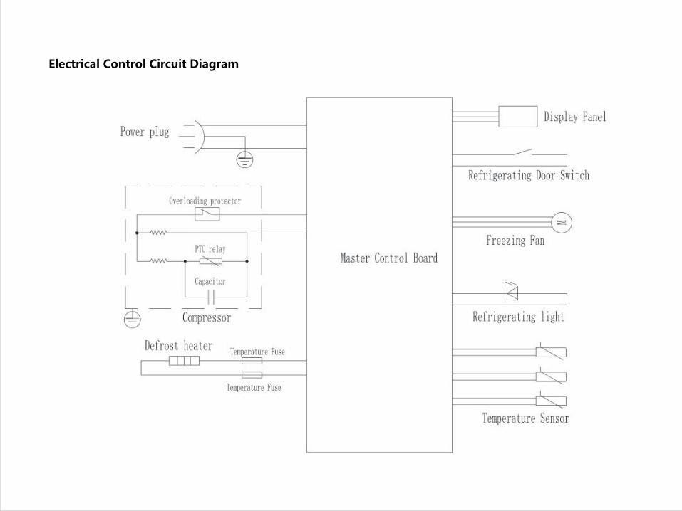
Electrical Control Circuit Diagram
Composition of electrical control system:
1. Compressor — refrigeration device;
2. Refrigerating light — used for lighting in refrigerating chamber;
3. Freezing fan — used for cooling capacity transmission and air circulation;
4. Steel tube heater — used to remove frosting on the surface of freezing evaporator;
5. Refrigerating switch — used to control the lighting in refrigerating chamber;
6. Temperature sensor — used to sense temperature;
7. Temperature fuse — used to cut off the connection between the steel tube heater and the power supply when
the defrosting temperature is abnormal.

Control of components
(1) Compressor
If refrigeration is required, turn on the compressor; if not, turn off the compressor;
The downtime of the compressor must be more than 8 minutes before it can be started again;
(2) Light
When the refrigerating door is opened, the refrigerating light will be on.
When the refrigerating door is closed, the refrigerating light will go out;
The light will go out if it is continuously on for more than 5 minutes.
(3) Fan
In normal refrigeration process, every time the compressor is turned on, the freezer fan will be turned on.
When the compressor stops, the freezing fan will be turned off.
During the freezing and defrosting process, the freezing fan will be turned off;
If the refrigerating door is detected to be open, the freezing fan remains off;
(4) Heating wire for steel tube
In the defrosting state, the steel tube heating wire will be turned on;
In other states, the steel tube heater will be turned off.
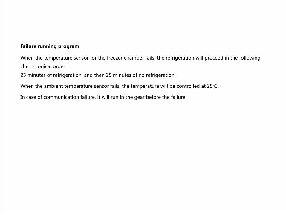
When the temperature sensor for the freezer chamber fails, the refrigeration will proceed in the following
chronological order:
25 minutes of refrigeration, and then 25 minutes of no refrigeration.
When the ambient temperature sensor fails, the temperature will be controlled at 25℃.
In case of communication failure, it will run in the gear before the failure.
Failure running program
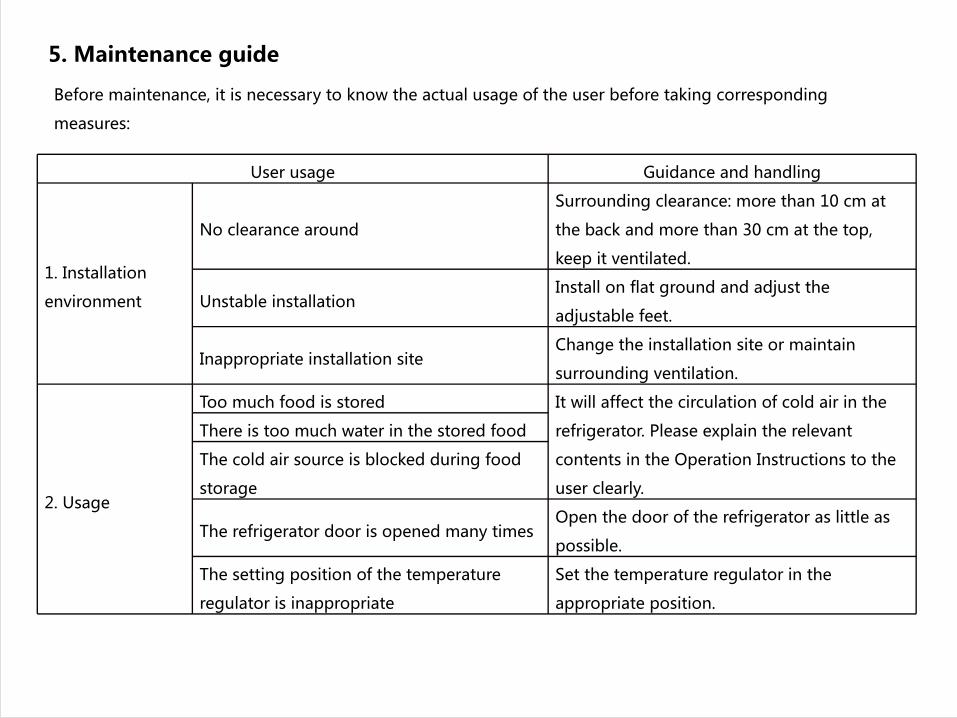
5. Maintenance guide
Before maintenance, it is necessary to know the actual usage of the user before taking corresponding
measures:
User usage Guidance and handling
1. Installation
environment
No clearance around
Surrounding clearance: more than 10 cm at
the back and more than 30 cm at the top,
keep it ventilated.
Unstable installation Install on flat ground and adjust the
adjustable feet.
Inappropriate installation site Change the installation site or maintain
surrounding ventilation.
2. Usage
Too much food is stored It will affect the circulation of cold air in the
refrigerator. Please explain the relevant
contents in the Operation Instructions to the
user clearly.
There is too much water in the stored food
The cold air source is blocked during food
storage
The refrigerator door is opened many times Open the door of the refrigerator as little as
possible.
The setting position of the temperature
regulator is inappropriate
Set the temperature regulator in the
appropriate position.
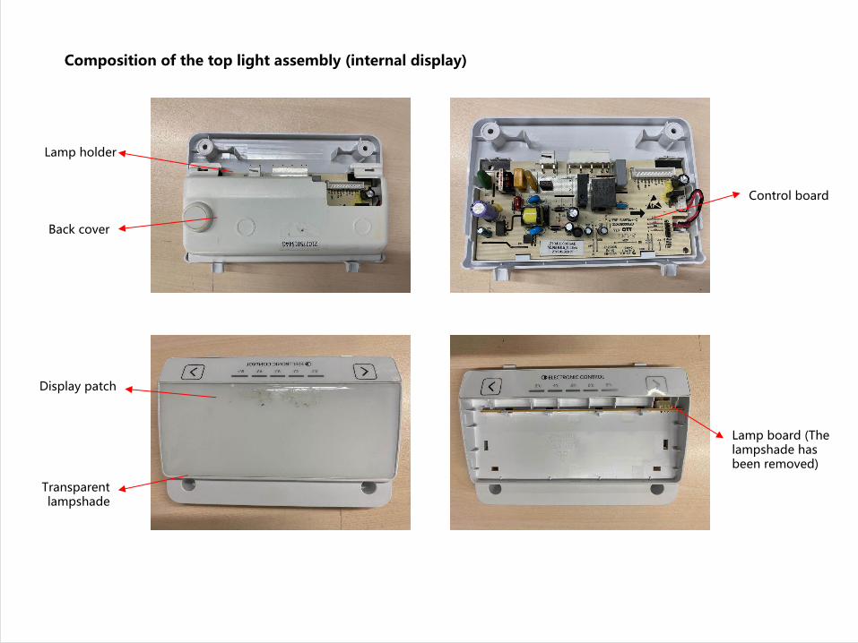
Composition of the top light assembly (internal display)
Lamp holder
Back cover
Control board
Lamp board (The lampshade has been removed)
Display patch
Transparent lampshade

Composition of the top light assembly (external display)
Lamp holderLamp holder
Back cover
Display patch
Transparent lampshade
Control board
Lamp board (The lampshade has been removed)

Removal of the top light
Step II: Pull down the top light from the rear
as shown in the figure, and unplug the plug-
in terminal
Step I: Remove the 2 screws at the rear of the assembly
State after the removal
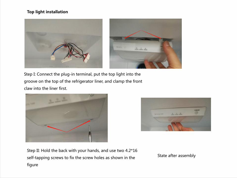
Top light installation
Step I: Connect the plug-in terminal, put the top light into the
groove on the top of the refrigerator liner, and clamp the front
claw into the liner first.
Step II: Hold the back with your hands, and use two 4.2*16
self-tapping screws to fix the screw holes as shown in the
figure
State after assembly
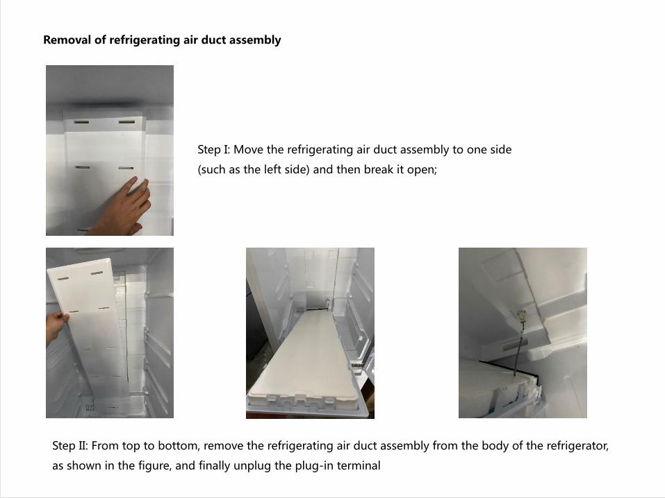
Removal of refrigerating air duct assembly
Step I: Move the refrigerating air duct assembly to one side
(such as the left side) and then break it open;
Step II: From top to bottom, remove the refrigerating air duct assembly from the body of the refrigerator,
as shown in the figure, and finally unplug the plug-in terminal

Installation of refrigerating air duct assembly
Step I: Connect the plug-in terminal shown in the figure, and install the lower end of the
refrigerating air duct assembly into the body of the refrigerator first
Step II: Install the refrigerating air duct into the body
of the refrigerator from bottom to top State after assembly
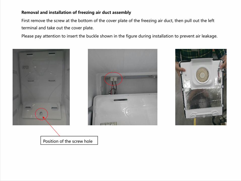
Removal and installation of freezing air duct assembly
First remove the screw at the bottom of the cover plate of the freezing air duct, then pull out the left
terminal and take out the cover plate.
Please pay attention to insert the buckle shown in the figure during installation to prevent air leakage.
Position of the screw hole
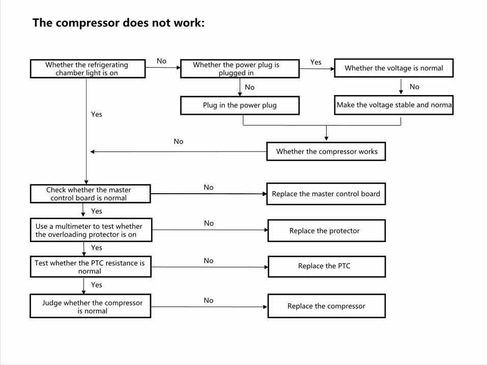
The compressor does not work:
Whether the refrigerating chamber light is on
Use a multimeter to test whether the overloading protector is on
Replace the master control boardCheck whether the master control board is normal
Whether the compressor works
Make the voltage stable and normal Plug in the power plug
Whether the voltage is normalWhether the power plug is plugged in
Test whether the PTC resistance is normal
Judge whether the compressor is normal
Replace the PTC
Replace the compressor
Replace the protector
No Yes
No
Yes
No
No
No
Yes
Yes
Yes
No
NoNo

Excessive noise:
Excessive noise
Avoid collision with objectsResonance with objects through collision
Whether the ground is flat Keep the ground level No
Yes
Yes
No
Whether the pipelines in the compressor compartment collide with each other
YesAdjust the pipeline to avoid collision
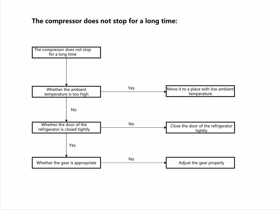
The compressor does not stop for a long time:
The compressor does not stop for a long time
Whether the gear is appropriate
Close the door of the refrigerator tightly
Whether the door of the refrigerator is closed tightly
Whether the ambient temperature is too high
Move it to a place with low ambient temperature
Adjust the gear properly
Yes
No
No
No
Yes