Embed Size (px)
Citation preview

Refrigeration and Air Conditioning Prof. M. Ramgopal
Department of Mechanical Engineering Indian Institute of Technology, Kharagpur
Lecture No. # 14 Vapour Absorption Refrigeration Systems
(Refer Slide Time: 00:00:43 min)
Welcome back in the last few lectures we discussed compression refrigeration systems.
(Refer Slide Time: 00:00:55 min)
1

So in this lecture I shall introduce another very important refrigeration system known vapour
absorption refrigeration system.
(Refer Slide Time: 00:01:01 min)
So the specific objective of this particular lesson are to introduce basic concepts of vapour
absorption refrigeration systems, introduce simple vapour absorption refrigeration system derive
expression for maximum COP, discuss properties of ideal and real solutions, describe a basic
vapour absorption refrigeration system with solution heat exchanger and finally discuss desirable
properties of refrigerant absorbent mixtures.
(Refer Slide Time: 00:01:31 min)
2

At the end of this lesson you should be able to explain basic principles of absorption refrigeration
systems estimate maximum COP of absorption refrigeration systems, differentiate between ideal
and real solutions, describe the basic absorption refrigeration system with solution heat
exchanger and finally list desirable properties of refrigerant absorbent pairs.
(Refer Slide Time: 00:01:56 min)
let me give a brief introduction vapour absorption refrigeration systems belong to the class of
vapour cycles similar to vapour compression refrigeration systems okay. That means they are
just like vapour compression systems these are also vapour cycles. That means as I have already
explained the working fluid undergoes a phase change during the cycle. So they are vapour
cycles like compression systems but there is one major difference between absorption systems
and compression systems what is the difference. Unlike vapour compression refrigeration
systems the required input absorption systems is mainly in the form of low grade thermal energy
if you remember in the compression system the major input or the input to the system is in the
form of mechanical energy to run the compressor okay.
So that is you can call that as a work of evaporator system where as in absorption refrigeration
systems the main input to the system is in the form of low grade thermal energy or heat. That is
why these systems are also known as heat operated systems or thermal energy driven system
okay. This is the major difference between compression system and absorption systems these
3

absorption systems are also widely used in various refrigeration and air conditioning
applications.
(Refer Slide Time: 00:03:08 min)
Since absorption refrigeration systems run on low grade thermal energy they are preferred when
low grade energy such as waste heat or solar energy is available. There are many industries and
many situations where plenty of low grade thermal energy is either rejected its not used properly
okay in such circumstances one can use vapour absorption refrigeration systems by tapping the
low grade thermal energy. Our typical example is the waste heat rejected in many of the process
plant etcetera or you can also use other low grade energy sources such as solar energy to drive
the vapour absorption system.
This is one of the main applications and advantages of absorption systems compare to
compression systems. That means you can use low grade energy sources okay. And since the
working fluids used in absorption systems are mainly natural working fluid. That means you use
either water or ammonia which are natural refrigerants these systems are environment friendly
okay. These are two most important advantages of absorption systems compare to vapour
compression refrigeration systems. So as I said since conventional absorption systems use
natural refrigerants such as water ammonia they are environment friendly.
4

(Refer Slide Time: 00:04:22 min)
So let us look at some basic concepts. So first basic concept is that when a solute for example
such as lithium bromide salt is dissolved in solvent example water. The boiling point of the
solution is elevated okay, this you can also state in another way for example if you are keeping
the temperature constant and if you are dissolving the solute in a solvent then the effect of this
dissolving is to reduce the vapour pressure of the solvent below that of it saturation pressure at
that temperature. This is the basic concept based on which the absorption systems have been
built okay. So now let us look at the most basic absorption system.
(Refer Slide Time: 00:05:05 min)
5

In the basic absorption system refrigeration is obtained by connecting two vessels with one
vessel containing pure solvent. So we call it as refrigerant and the other containing the solution
which is the mixture of refrigerant plus absorbent. At equilibrium the temperature of the solution
will be higher than that of the pure refrigerant when the pressures are same obviously. As I have
mentioned already the temperature of the solution will be higher than that of the pure solvent and
if the solution is at ambient temperature obviously the solvent. That means refrigerant will be at
a temperature lower than the ambient. That means there is a temperature difference between the
ambient and the solvent. So this is the temperature difference using which you can produce a
refrigeration effect. So this is the basic principle. Now let me explain this with the schematic.
(Refer Slide Time: 00:05:54 min)
What I have shown here, let us look at the initial conditions initially we have two vessels A and
vessel B. Vessel A consists of pure water at thirty degree centigrade and vessel B consists of a
solution of water and lithium bromide fifty percent lithium bromide by mass okay. So one is the
pure solvent that is water the other one is mixture of water and lithium bromide salt. Let us say
that initially the valve is closed and the entire system is in thermal equilibrium with surroundings
which is at thirty degree centigrade. So every where you have thirty degree centigrade in vessel
B as well as vessel A and vessel A and B are isolated okay. So now what is the vapour pressure
in vessel A and what is the vapour pressure in vessel B if you look at the steam tables or steam
6

charts we will find that at thirty degree centigrade the saturation pressure of water is four point
two four kilo Pascal.
That means the pressure inside the vessel A that means this side of the system is four point two
four kilo Pascal which is nothing but the saturation pressure of water at thirty degree centigrade.
Now what is the pressure on in vessel B since in vessel B we have we do not have pure water.
But we have a solution obviously at the same temperature there will be a lower vapour pressure
and if you look at the properties of lithium bromide water solution we will find that at fifty
percent concentration and at thirty degree centigrade the pressure here is one point two two kilo
Pascal.
These are the pressure at equilibrium conditions now you can maintain the pressures at different
values because the valve is closed. Now let us say that we have opened the valve okay. Now
come to this second part we open the valve initially what happens. Because of the pressure
difference the vapour flows from this side to this side and since the solution lithium bromide
water solution has an affinity for water vapour the water vapour gets absorbed here okay. So that
means the water vapour is absorbed here and the pressure try to tries to be same in both the
vessels okay.
So every where you have the uniform pressure now suppose by some means we are able to
maintain the concentration and temperature in vessel B okay. Lets the discuss how we can do
this a little later but for the time being assume that we are able to maintain the composition and
temperature. Then what will be the pressure in the entire system the pressure in the entire system
will be one point two two kilo Pascal which is decided by the solution and this is nothing but the
equilibrium vapour pressure at this composition and this temperature. So on this side also you
have one point two two kilo Pascal okay. If you have one point two two kilo Pascal here what
will be the water temperature.
So again if you look at the steam tables or charts you will find that at one point two two kilo
Pascal this temperature at equilibrium is nothing but the saturation temperature corresponding to
this pressure. That means you will have ten degree centigrade temperature in the vessel A okay.
That means by having this combination and by opening the valve I could reduce the temperature
from thirty degrees to ten degrees centigrade okay. And as long as you can maintain the
conditions in B the conditions in A can be maintained at one point two two kilo Pascal and ten
degree centigrade.
7

Now the outside temperature is thirty degree centigrade and the water is at ten degree centigrade.
And let us assume that we do not have we have diathermic valve that means heat can be
transferred from outside to the water. So there is heat transfer from the surroundings to the water
and as a result of the heat transfer the water will evaporate okay. And this vapour continuously
flows from vessel A to vessel B where it gets absorbed now the absorption process is an
exothermic process in this case so heat released. And since you want to maintain the temperature
at thirty degree centigrade this heat has got to be continuously rejected to the surroundings. That
means during this step what we are doing is we are adding heat at vessel A and we are rejecting
heat at vessel B.
And you are able to produce refrigeration effect here because you are able to transfer heat from
the surroundings to a body at ten degree centigrade okay. That is why you are getting a
refrigeration effect here. Now if you have a finite sized vessels let us say, that means A and B are
finite sized then you have a finite amount of water in vessel A and finite amount of solution in
vessel B and as a result of this water vapour transfer from vessel A to B at a point may come
where vessel A may become empty or this may become saturated okay. That means once if this
becomes take the first case when this vessel becomes empty means empty of liquid then there
will not be any more heat transfer because nothing can evaporate okay. So the refrigeration effect
stops here okay.
That means by this means whatever refrigeration effect you are able to produce that is
intermittent and it will stop after some point when you are using finite vessels okay. So this is the
so what do what we have to do to continue this process to continue this process what we have to
do is we have to bring back this system to its original position okay. So how do we do that we do
that by reason rating the water vapour okay. So let us see what is the reason rating process okay.
8

(Refer Slide Time: 00:11:10 min)
So this is this picture here shows the process of regeneration during the regeneration process
what we do is initially we keep the valve closed and bring the vessels A and B vessel A and B
again to equilibrium with the surroundings. So again everything will be at thirty degrees
centigrade. Now open the vessel open the valve and supply heat to vessel B okay. Now this due
to the vapour transfer in the previous step this solution is weak that means it has more water
vapour okay so when you are supplying heat at a particular temperature T g okay. When you are
supplying heat then water is generated at this point and this water vapour flows from this side to
this side and if you are able to keep this at thirty degree centigrade. Then the water vapour is
coming here it will condense at this pressure and at this temperature.
Since this is an exothermic process heat of condensation is rejected to the surroundings okay.
That means during the regeneration process what we are doing we are supplying heat at high
temperature T g to the solution. So that vapour is generated and this vapour comes to the solvent
side and it condenses by rejecting heat of condensation okay. So by you are transferring the, you
are reversing the process and you are transferring water from the solution to the pure solvent side
okay. This process will continue till you get the required amount of water on this side okay. Then
to complete the process again you have to close the valve and bring these both the vessels to
equilibrium with the surroundings at thirty degree centigrade so the process continues okay. So
one thing you can notice here is we have so three temperatures here one is the T g which is
9

nothing but the temperature at which heat is supplied to the solution for regeneration okay. Let
us call that as generated temperature T g okay.
And we have another temperature called the heat sink temperature. That means the temperature
at which heat is rejected during absorption process and during the condensation process okay, T
naught and finally we have the refrigeration temperature T e okay. It is the temperature at which
refrigeration produced obviously T g is greater than T naught is greater than T e okay. This
relation holds good and now how do we decide the, what should be this temperature and how
much heat has to be supplied and all that depends upon the temperatures for example the amount
of heat transferred these depend upon the properties of solution and the refrigerant and also the
operating conditions okay.
So this is the basic principle of a very simple vapour absorption refrigeration system okay. So to
summarize what we have done is we have taken two vessels in one vessel we have kept pure
solvent and in the other vessel we have a solution okay. So by manipulating the pressures inside
the supplying heat or by rejecting heat we could transfer vapour from the pure refrigerant side to
the solution side during the refrigeration process and from the solution side to the refrigerant side
during the regeneration process okay. And during this entire process we could get refrigeration
effect during one step and we have to supply heat at high temperature during the regeneration
process. And heat is rejected in both the processes of refrigeration and regeneration okay. So this
is an intermittent system that means you are not able to get refrigeration continuously okay. So
you call this as an intermittent absorption refrigeration system okay.
10

(Refer Slide Time: 00:14:37 min)
So as I said the you call this as an intermittent system so with only two vessels the refrigeration
obtained is intermittent so no refrigeration effect is produced during vapour regeneration and
these simple systems also have some applications they can be used to provide refrigeration using
renewable energy such as solar energy. For example you would like to produce refrigeration
using solar energy okay. So you can have a very simple intermittent system consisting of this
simple two vessels and with a valve and connections okay.
What you have to do is during the day time when solar energy is available refrigerant is
generated okay. And it is stored as pure refrigerant okay during the day time the, if the, it is the
process of regeneration. And during night time what happens is surroundings become cold okay
then the process gets reversed. Because the solution becomes cool so the refrigerant in the vessel
pure refrigerant vessel can boil by taking heat from the surroundings okay. That means you get
refrigeration effect during the night and you have to regenerate the refrigerant during the day
time.
Such systems are very good for very remote and rural areas where you do not have any electrical
electricity supply or you want a system which is independent of your great power okay. Such
systems have been built and there have been used by successfully in many remote areas okay. So
they are known as intermittent absorption refrigeration systems. But in practice in most of the
applications we require continuous refrigeration okay, when you want a refrigeration
11

continuously obviously you cannot use this simple system with two vessels. So you have to do
certain modifications.
(Refer Slide Time: 00:16:18 min)
So this brings us to a basic vapour absorption refrigeration system for continuous output. So
continuous refrigeration can be obtained with a modified system consisting of two pairs of
vessels and additional components such as expansion valves and solution pump. So you have to
have first thing is two pairs of vessels. That means you will have four vessels in addition to that
you also have to have some additional components such expansion valves and a solution pump.
These systems are similar to compression systems. That means you get continuous output just
like a vapour compression system but there are two major differences the major difference is the
way the vapour is compressed.
In a mechanical, it is mechanical compression in vapour compression refrigeration system. That
means you use mechanical energy supply the mechanical energy to the compressor and compress
the vapour mechanically okay. So you call these systems as mechanical compression systems
okay. And the in case of absorption system you can call that as thermal compression okay. If you
compress the vapour thermally now let me explain the basic system.
12
(Refer Slide Time: 00:17:23 min)
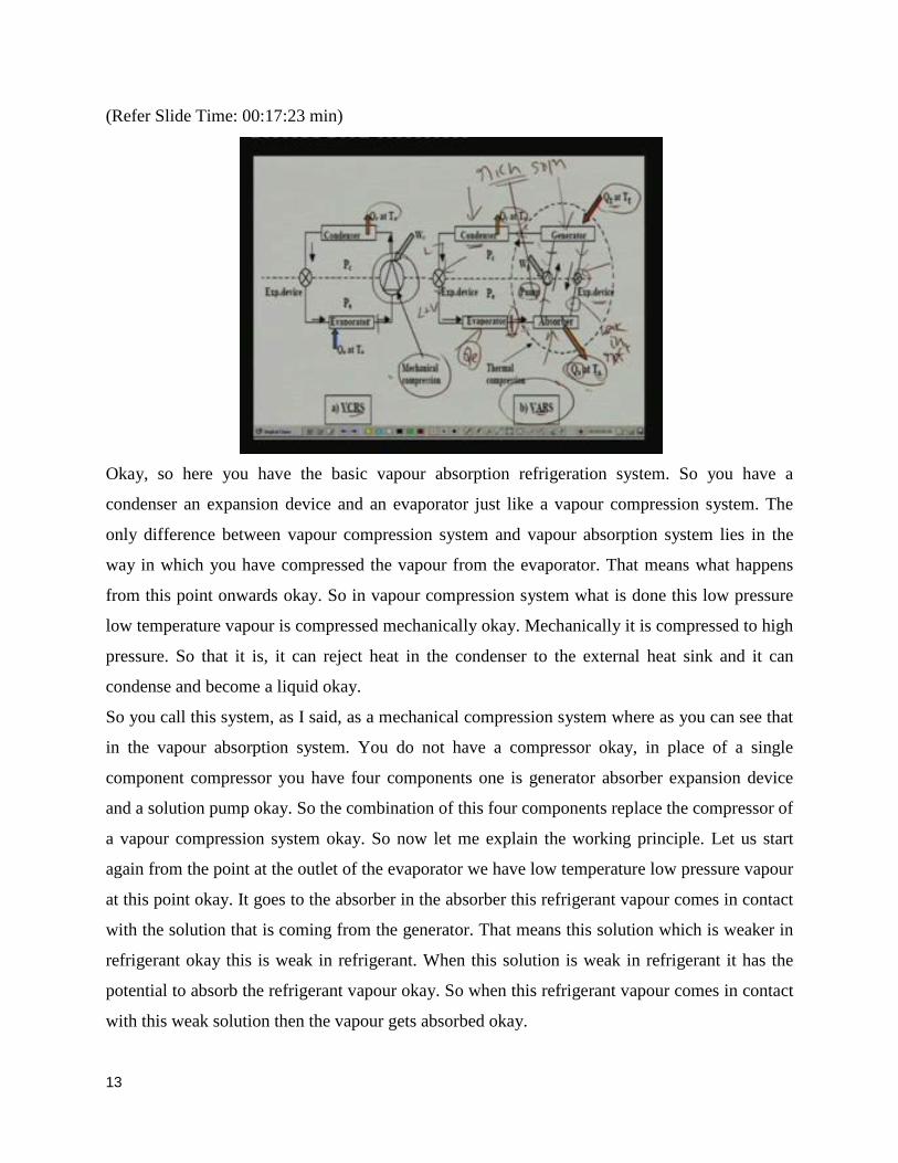
Okay, so here you have the basic vapour absorption refrigeration system. So you have a
condenser an expansion device and an evaporator just like a vapour compression system. The
only difference between vapour compression system and vapour absorption system lies in the
way in which you have compressed the vapour from the evaporator. That means what happens
from this point onwards okay. So in vapour compression system what is done this low pressure
low temperature vapour is compressed mechanically okay. Mechanically it is compressed to high
pressure. So that it is, it can reject heat in the condenser to the external heat sink and it can
condense and become a liquid okay.
So you call this system, as I said, as a mechanical compression system where as you can see that
in the vapour absorption system. You do not have a compressor okay, in place of a single
component compressor you have four components one is generator absorber expansion device
and a solution pump okay. So the combination of this four components replace the compressor of
a vapour compression system okay. So now let me explain the working principle. Let us start
again from the point at the outlet of the evaporator we have low temperature low pressure vapour
at this point okay. It goes to the absorber in the absorber this refrigerant vapour comes in contact
with the solution that is coming from the generator. That means this solution which is weaker in
refrigerant okay this is weak in refrigerant. When this solution is weak in refrigerant it has the
potential to absorb the refrigerant vapour okay. So when this refrigerant vapour comes in contact
with this weak solution then the vapour gets absorbed okay.
13

Since absorption process is an exothermic process heat is rejected to the atmosphere at
temperature T naught and this is the amount of heat rejection during this process okay. So the
weak solution and refrigerant vapour are combining heat is rejected. So as a result of this mixing
what you have is a rich solution okay this solution is rich solution rich solution means rich in
refrigerant. Now this rich solution is pump to the condenser pressure using a solution pump
okay. S solution pump is used to compress the vapour from the absorber from the compressor
liquid from the absorber to the condenser pressure okay.
And now at this point you have high pressure liquid now this high pressure liquid goes to the
generator in the generator what is done is heat is supplied at high temperature. Okay. So when
you supply heat at high temperature to the rich solution refrigerant vapour is generated okay. So
this refrigerant vapour at high pressure and high temperature goes to the condenser where it
rejects the heat to the surroundings condensers and becomes a liquid okay. And this liquid again
expands in the expansion device. So you have here a low quality liquid vapour mixer at low, at
low temperature and low pressure this enters into the evaporator it takes heat from the
surroundings produces the refrigeration effect and becomes the vapour again. So that is how the
vapour cycle is completed okay.
So the only difference you can notice here is instead of compressing it mechanically we have
compressed it thermally okay. Now what happens to the solution here remember that we had a
rich solution that is entering into the generator. So from that you have stripped off the refrigerant
so what you have is a weak solution okay. Now this weak solution is still at high pressure okay.
So to complete the cycle for the solution you have to reduce its pressure. So we use an expansion
device where the liquid pressure is reduced to that of the absorber or evaporator okay. And then
again it comes in contact with this vapour so the solution cycles also completed. So this process
goes on continuously as long as you supply heat here you reject heat at absorber and condenser.
And you have refrigeration effect continuously okay so this is the principle of very basic vapour
absorption refrigeration system.
14

(Refer Slide Time: 00:21:41 min)
And as I said you can see out the similarities just like vapour compression system you have two
pressure levels here P c and P e here P c and P e here okay. However unlike vapour compression
system there are three temperatures here. In vapour compression system we have only two
temperatures that is this is the T naught is the heat sink temperature and T e is the low
temperature heat source heat source temperature okay. Where as in absorption system we have
three temperatures one is T e that is low temperature source low source then T naught is the heat
sink temperature and T c is the high temperature heat source okay. At where from which you
supply heat to the generator so this is the three temperatures cycle and vapour compression
refrigeration system is the two temperatures cycle. Okay. So the major difference is you have
seen.
15

(Refer Slide Time: 00:22:44 min)
Now what is the advantage of this i mean you if you look at the components and the schematic
you will find that the vapour absorption system is lot more complicated compare to vapour
compression system we had only four components in vapour compression systems where as we
had seven components in vapour absorption systems okay. And you might have noticed that even
though we did not use a compressor we still used a pump in the vapour absorption system. Now
the pump requires mechanical energy okay. So both vapour absorption systems as well as vapour
compression systems both need the mechanical energy one to run the compressor and in other
case you need it for running the pump okay. And in addition to that you also have to supply heat
at high temperature okay.
Since mechanical energy is required in both the cases what is the advantage of absorption
systems compare to compression systems. The advantage is like this in the compression system
you are compressing a vapour okay. So the mechanical energy required to compress the vapour
is quite large. Where as in vapour absorption systems you are pumping a liquid and the work
required to pump a liquid for the same over the same pressure difference is much less compare to
the work required for compressing a vapour okay, this is the major difference. That means the
amount of mechanical energy required in vapour absorption systems is very small compare to
vapour compression refrigeration systems okay.
In fact it is practically negligible when you compare it with the heat input. So that is why the
absorption systems are mainly called as heat operated systems. Because that is the major heat
16

input is major input is in the form of heat okay. Why do, how do we say that energy required for
compressing a vapour is much higher than the energy required for pumping a liquid. Because
you have seen that the work input is simply equal to integral V D P. And the V is nothing but the
specific volume of the working fluid in one case you have vapour which has a very high specific
volume that is why the integral V D P is very high. Where as in absorption system you have a
liquid with very small specific volume.
So integral V D P is very small so the mechanical energy requirement is very small okay. So this
is the major difference and the major advantage of absorption systems over compression systems
okay. So that is what I have mentioned here work input required to pump liquid solution is much
less than the work required for compressing vapour. So the mechanical energy required to
operate absorption system is much less than that required to operate a compression system.
However of course you have to pay somewhere. So what you do in a instead of mechanical
energy you have to supply a large amount of low grade thermal energy to operate the absorption
system. And as I said the solution pump work is often negligible compare to the generator heat
input.
(Refer Slide Time: 00:25:28 min)
So if you are defining COPs just like the compression system you can see that the COP of the
compression system is defined as the refrigeration capacity divided by the power input to the
compressor W c where as the COP of vapour absorption system. You have two inputs and one
17

output is Q e input is the heat input Q g plus work input W p and as I have said W p is negligible
compare to Q g so COP of absorption refrigeration system is almost equal to Q e by Q g only
that means refrigeration capacity divided by the heat input to the generator okay. So this is the
major difference between again compression and absorption system in terms of COPs. Since
vapour absorption system uses low grade energy as input the COP of absorption system is
generally much smaller than COP of compression refrigeration system. Obviously if you are I
mean if you are comparing the COPs you get much higher COPs in case of compression systems
okay. Because the quality of the energy that you are supplying to the system is much higher
okay.
Work is high grade energy compare to heat okay so the COPs are larger okay. But of course
comparing the systems based on COP. So you can call also call the COP as the first law
efficiency comparing the efficiencies based on COPs is not really justified always because the
quality is different and the cost is also different okay.
(Refer Slide Time: 00:26:55 min)
That means comparing systems based on COPs is not fully justified as mechanical energy is
more expensive than thermal energy hence sometimes what we do is we define what is known as
the second law or exergetic efficiency to compare different refrigerant systems. And you will
find that the second law efficiency of absorption system is of the same order as that of a
compression system okay. That means if you are comparing the two systems based on COPs then
18

absorption system is definitely bad because you get very low COP4. But as I said since
numerator and denominator are of different qualities if you want get the real picture you must
convert them into the same quantity okay. That means you have to convert the numerator and
denominator in expression for COP into exergy. Let us say then you get what is known as second
law efficiency or exergetic efficiency.
When you are doing this you will find that the COP of I am sorry the exergetic efficiency of
absorption system is almost same as that of a compression system okay. So it does not look so
bad and when you are looking at the exergetic efficiency okay. This you can also justify this in
another way for example when you are talking about the COP of the compression system what is
the input is the work mechanical energy okay. Most of the time the mechanical energy is derived
from the electrical energy that means to run the compressor that is how you supply the electrical
energy okay.
And how do you get the electrical energy electrical energy is generated let us say in a thermal
power plant okay. And typical efficiency of the thermal power plant could be about forty percent
you are not really compare taking that efficiency into account when you are calculating the COP
of the vapour compression system okay. So take that efficiency also into account you will find
that compression system are not so efficient compared to vapour absorption system or in other
words both are equally good or bad okay.
(Refer Slide Time: 00:28:51 min)
19

Now when we discuss vapour compression refrigeration systems how if you remember how did
we begin we began with an ideal cycle okay. First we have defined an ideal cycle and we found
what is the maximum possible COP of this cycle. That means we found the maximum possible
COP of a compression system okay. And if you remember it was the Carnot COP okay. That
means the reverse Carnot cycle gives the maximum COP so first we obtained the expression for
the COP of the reverse Carnot cycle and then we obtained the expression for the COPs for the
real cycles okay.
And if you remember I said that the objective of this is to compare how good is the actual cycle
with the best possible or with the ideal cycle okay. So in case of the absorption system also let us
first look at what is the maximum possible COP okay. Then we will move on to the actual
systems. So as I said for compression refrigeration systems the maximum COP is given by
Carnot COP and Carnot COP if you remember is simply given by T e divided T c minus T e
where T e and T c are evaporator and condenser temperatures. However in simple absorption
refrigeration system we have three temperatures. So when you have three temperature levels how
do you get the maximum COP okay one thing is for sure that the COP will be maximum when
the system is totally reversible.
That means when you have an ideal vapour absorption refrigeration system where it is reversible
internally as well as externally okay. That means a total reversible system. So the COP of ideal
vapour absorption refrigeration system can be obtained by applying first and second laws of
thermodynamics okay. So what we do is we take a ideal system and then you apply the first and
second laws of thermodynamics. Let me show how we can do this.
20

(Refer Slide Time: 00:30:44 min)
Okay, what I have shown here is the basic vapour absorption refrigeration system this is the
absorption refrigeration system which is operating in a cyclic manner okay. You can see the
cycle and here we have three temperatures. As I said generated temperature evaporated
temperature and the heat sink temperature and this figure also shows various energy flows okay.
For example you take high temperature heat input Q g to the system near the generator and this
system takes low temperature heat input Q e at refrigeration temperature T e and it rejects heat to
the heat sink.
And heat rejection takes place at the absorber Q a plus condenser Q c okay. So heat rejected is Q
a plus Q c where as heat input is Q g and Q e Q g is at the generator and Q e is at the evaporator
in addition to that we also supply mechanical energy to run the pump okay W p. So these are the
total energy flows in a simple vapour absorption refrigeration system. So if you apply first law of
thermodynamics what is the first law of thermodynamics if you remember simply you have
okay. And for the cycle the net energy change is zero because the working fluid is undergoing
the cyclic process okay. So what is the energy change cyclic energy change you can simply write
this as Q e plus Q g minus Q c plus a Q c plus a is nothing but Q c plus Q a okay plus W p is
zero.
This is nothing but this expression where as I said Q e and Q g are positive. Because you are
supplying them to the system this is negative because this is the heat rejected from the system
21

and work input required for the pump is also positive. Because that is also supplied okay, so
whatever is supplied to the system is positive and whatever is rejected from the system is
negative okay. So this is how you get the first law of thermodynamics very simple energy
balance now what is the second law of thermodynamics. We write the second law of
thermodynamics in the form of entropy change and if you remember the second law of
thermodynamics say that the total entropy change.
That means the entropic change of the system plus surrounding will always be greater than or
equal to zero. And this equal sign is for completely reversible if everything is reversible and the
greater than is for irreversible systems okay. So this is the second law of thermodynamics right
now let us write the expression for delta surroundings in terms of Q e Q g and Q c. Now what is
the entropy change of the system obviously entropy change of the system is zero right so delta S
system is zero because the working fluid is undergoing a cyclic process okay.
So delta S system is zero right that means ultimately the second law of thermodynamics when
you apply to this simply becomes delta S total is equal to delta surrounding which is greater than
and equal to zero okay.
(Refer Slide Time: 00:33:51 min)
Now as I said delta S system is zero because this system undergoes a cyclic process okay. Now
we write the expression for delta S surroundings means we have three temperature reservoirs one
is the low temperature reservoir T e the other one is at high temperature reservoir T g and this is
22

the medium temperature heat sink at T naught okay. And what is the entropy change of these
reservoirs the entropy change of low temperature reservoir is this minus Q e by T e minus
because the reservoir is loosing heat okay. And its temperature is constant okay. So delta S if you
remember is Do Q by T because you are the reservoir is undergoing the reversible change. So
you can write this and T is constant. So simply this becomes one Q two or whatever it is delta Q
divided by that particular temperature.
So when you are applying this to the evaporator this becomes minus Q e by T e when you apply
this to the generator this becomes minus Q g by T g and when you are applying this to the heat
sink this becomes plus because heat sink is taking the energy. And this energy is taken at
temperature T naught okay. So this is the expression for the entropic change of the surroundings
okay now you combine the first and second law so you get this expression okay. This expression
relates the Q g and Q e what we are doing is we are eliminating Q a plus c by using the first law
okay. So you that is eliminated and you and then get this expression.
Now if you are neglecting pump work okay. That means you are neglecting pump work and if
you define COP as we have seen COP is equal to Q e divided by Q g okay. You will find that
from this expression COP of vapour absorption refrigeration system is given by this expression
okay. That means always less than or equal to T e divided by T naught minus T e into T g minus
T naught by T g where remember that T g is the generated temperature which is the highest
temperature in the cycle T naught is the heat sink temperature and T e is the lowest temperature
of the evaporator okay.
23

(Refer Slide Time: 00:36:03 min)
Now for a totally because we started this discussion with a view to find out the maximum COP
okay. So as I said maximum COP takes place when the system is ideal okay. And for an ideal
system entropy change is zero okay entropy change of system is zero for both ideal as well as
real system because it is a cyclic process so for an ideal system in addition to this also should be
zero okay. That means delta S surroundings for a cut completely reversible system is equal to
zero so if you are equating this from the earlier expression you will get this expression okay.
From this expression you get the COP for an ideal system this is the maximum possible COP of
okay, of any vapour absorption refrigeration system operating between three temperatures T e T
naught and T g okay.
Now if you look at this expression you will notice an interesting thing. For example you take a
look at this quantity okay. And look at this quantity this quantity for example looks like the
Carnot COP of a vapour compression system okay. Because if you remember Carnot COP is
simply given by T e divided by T c minus T e where T c is equal to T naught in this case. So this
particular quantity is nothing but the COP of the Carnot system and what is this quantity this
quantity is nothing but the efficiency of Carnot heat engine okay. So the ultimately the COP of
an ideal vapour absorption system is shown to be a product of Carnot COP into Carnot heat
engine okay.
24

(Refer Slide Time: 00:37:43 min)
That means you can show an ideal vapour absorption system as a combination of Carnot heat
engine and Carnot refrigerator okay. So what you are doing is this is the generator okay. You
supply Q g from the generator to a Carnot heat engine and produce work and reject some heat to
the surroundings. And this work is used to run a Carnot refrigerator okay. So the same work is
supply to run a Carnot refrigerator and this refrigerator takes heat from the low temperature
surroundings Q e and again it rejects the heat to the heat sink T naught. And the efficiency of this
heat engine is nothing but T g minus T T naught by T g and COP of this Carnot cycle is, if you
remember T e divided by T naught minus T e.
So the combined efficiency of this n combined is nothing but the efficiency of this multiplied by
the efficiency of this that is n E into COP R okay. So that is how you can split a three
temperature refrigeration system as a combination of two temperature systems.
25

(Refer Slide Time: 00:38:57 min)
So you can see that, so from this you can easily infer that the COP of an ideal vapour absorption
system increases as the evaporator temperature increases as the generator temperature increases
and the heat sink temperature decreases. When generated temperature increases and heat sink
temperature decreases the heat engine efficiency increases okay. And similarly when the
evaporator temperature increases and the condenser temperature reduces the COP of the Carnot
refrigerant cycle increases.
As a result of it the combined efficiency improves okay. So if you want to have a very high COP
of a vapour absorption refrigeration system an ideal system you have to operate the system at as
higher generated temperature is possible as high an evaporator temperature is possible and as low
the heat sink temperature as possible okay. However you will find that the COP of actual system
will be much smaller than the ideal COP due to various internal and external irreversibilities. So
as usual you will find that all real systems will gives you COPs which are much smaller than the
ideal system COP okay.
This is mainly because of the irreversibilities. So remember that an ideal difference between
ideal and real cycle is lies in the irreversibilities okay. So in the real cycle you have
irreversibilities both internal as well as external okay. For example what are the internal
irreversibilities internal irreversibilities could be pressure drop due to friction it could be in this
case irreversibilities due to mixing right. And the external irreversibilities are irreversibilities due
to temperature difference between the working fluid and the external heat sink or source okay.
26

So mainly there are temperature differences so these are the different reversibilities which are a
must in a real system okay. So as a result the real system COP will be much less than the ideal
vapour absorption refrigeration system COP okay.
(Refer Slide Time: 00:40:58 min)
Now let us look at properties of refrigerant absorption mixtures the solution used in absorption
refrigeration systems may be considered as a homogeneous binary mixture of refrigerant and
absorbent okay. Because you have, so noticed that in the thermal compression part of the vapour
absorption system we have a solution okay. Solutions circulates to the components and this what
is the solution. The solution is nothing but a mixture of refrigerant and absorbent and for
simplicity we assume that it is a binary mixture. And it is a homogeneous mixture okay. Now
depending upon the boiling point difference between the refrigerant and absorbent and the
operating temperatures one may encounter a pure refrigerant vapour or a mixture of refrigerant
and absorbent vapour in generator of the absorption system okay.
That means while discussing the, or describing the simple vapour absorption refrigeration
system. I mention that in the generator you supply heat at high temperature and refrigerant
vapour is generated okay. And that refrigerant vapour goes to the condenser and gets condensed
and all that but in actual systems depending upon the boiling point temperature difference
between the refrigerant and absorbent in addition to the refrigerant vapour you may also have
some vapour of the absorbent in the generator okay.
27

That means when you are supplying heat to the generator both refrigerant as well as absorbent
may boil okay. That means what goes to the condenser may not be pure refrigerant but a mixture
of refrigerant and absorbent vapors okay. Whether you have a mixture or a pure refrigerant
purely depends upon the boiling point temperature difference between the refrigerant and
absorbent. If you have a very high boiling point temperature difference that means when the
absorbent is non volatile then you will find that whatever is generated in the generator is pure
refrigerant okay. On the other hand if the temperature difference is not too high that means
absorbent is also volatile then both will be generated in the generator okay. An example of the
first case where you have non volatile absorbent is when you use water and lithium bromide
okay so where lithium bromide is absorbent it is non volatile. So pure water vapour is generated
where as if you use ammonia water systems where water is absorbent and ammonia is refrigerant
both water and ammonia may be generated in the generator okay. So this is the difference
between different refrigerant absorbent pairs okay.
(Refer Slide Time: 00:43:20 min)
Now properties of binary solutions are evaluated from pressure temperature composition data. So
if you want to find the properties you have to specify pressure temperature and composition
of the solution can be expressed either in mass fraction or in mole fraction okay. So what is the
mass fraction mole fraction?
28

(Refer Slide Time: 00:43:48 min)
So mass fraction is defined as okay mass fraction is also sometimes called as concentration of
component one xi one is simply defined as the mass of that particular component divided by the
total mass of the solution okay. That means m one divided by m one plus m two similarly mass
fraction or concentration of component two is nothing but mass of that component in the solution
m two divided by the total mass of the solution okay. M one and m two are mass of component
one and two so for a binary system you can very easily show that xi one plus xi two is equal to
one from the above expression that means xi two is equal to one minus xi one okay. So if you
know the composition of one component the composition of the other component can be easily
obtained okay.
Now the composition in terms of mole fraction, so instead of talking about masses we talk about
the number of moles so mole fraction of component one is nothing but the ratio of number of
moles of component one divided by the total number of moles of component one and two in the
solution okay. Similarly mole fraction of two x two is given by n two by n one plus n two where
n one and n two are number of moles of components one and two okay. Just like the mass
fraction it can be very easily show shown that x one plus x two is equal to one or x two is equal
to one minus x one.
29

(Refer Slide Time: 00:45:09 min)
And very another, very important property as far as refrigerant absorbent pairs are concerned is
what is known as miscibility okay. And miscibility is an important property and it depends upon
the operating conditions. That means under certain operating conditions a refrigerant absorbent
pairs may not be very highly miscible where as at other condition there may be highly miscible
okay. So it depends upon the operating conditions and generally refrigerant absorbent pairs must
be completely miscible both in liquid as well as vapour phases. So that is how you choose the
pairs. So that they get mixed completely and you get a homogeneous mixture.
(Refer Slide Time: 00:45:45 min)
30

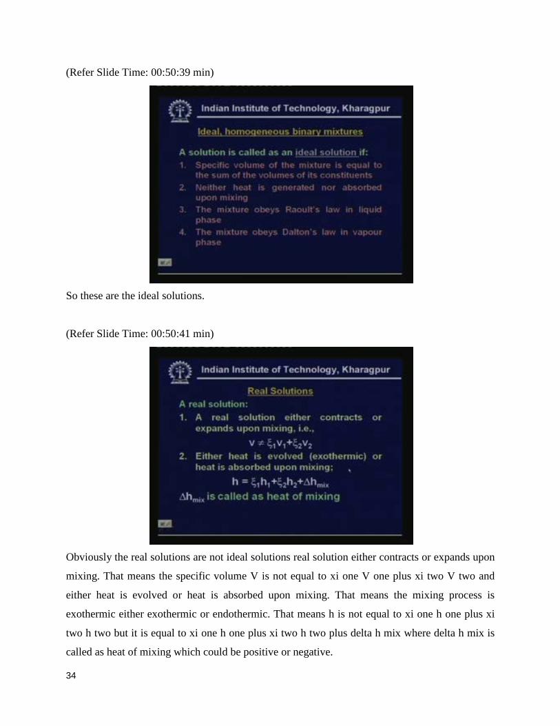
Now let us define what is known as an ideal homogeneous binary mixtures okay. A solution is
called as an ideal solution if specific volume of the mixture is equal to the sum of the volumes of
its constituents. That means, let us take a binary mixture i take a component one and component
two component one has a specific volume of v one and component two has specific volume v
two and I mix certain masses of these two components. You will find that the specific volume of
the mixture is simply equal to the volume of its constituents okay. Some of the volume of its
constituents okay.
Then during this mixing process neither heat is generated nor absorbed okay. So this is another
characteristic of ideal solution and the mixture obeys Raoult’s law in liquid phase and the
mixture also obeys Dalton’s law in vapour phase. So these are the four conditions they are not
totally unrelated actually these conditions are related. But these are based on these four points
you can say whether the solution these has an ideal solution or not okay. So let us look at
mathematically what do we mean by this?
(Refer Slide Time: 00:46:59 min)
So condition one condition one as I mentioned the solution of the specific volume of the solution
should be simply equal to sum total of the specific volumes of the components okay. So this is
the mass fraction of component one and this is specific volume of component one this is the
mass fraction of component two this is specific volume of component two okay. So the specific
31

volume of the mixture is simply equal to this means the solution neither expands nor contracts
that means there will be not be any volume change upon mixing okay.
So this is of a condition one and condition two the specific enthalpy okay. Since no heat is
released or absorbed it can be very easily shown that the specific enthalpy of the solution is
simply equal to the weighted average enthalpies of component one and component two okay.
xi one and xi two as I said are mass fractions h one and h two are the specific enthalpies of
component one and two at that particular temperature and pressure okay. So the same thing can
be written in this form. Because xi one and xi two is equal to one minus xi one this is the
condition second condition.
And what is Raoult’s law? Raoult’s law says that for an ideal solution the vapour pressure
exerted by component one is simply equal to the product of its liquid phase mole fraction x one x
one is equal to liquid phase mole fraction okay. So it is a vapour pressure exerted by the
component one is equal to a product of liquid phase mole fraction x one into P one sat what is P
one sat P one sat is nothing but the saturated pressure of this component one at that particular
temperature T okay. So P one sat is this so the vapour pressure is given for component one is
given by this for component two is given by this okay, where x two is liquid phase mole fraction
of component two.
So this is what is known as Raoult’s law okay. So if you know the composition and if you also
know the saturation properties you can find out what is the vapour pressure in solution okay.
What is Dalton’s law, if you remember Dalton’s law is for the vapour phase and it is says that
vapour pressure in vapour phase is equal to the mole fraction of component one in vapour phase
into the total pressure P total. Similarly the vapour pressure for component two is equal to the
product of mole fraction y two into the total pressure okay. This is the Dalton’s law okay.
32

(Refer Slide Time: 00:49:27 min)
So you can easily show that the vapour phase mole fractions y one and y two are related by this
expression y one plus y two is equal to one just like your liquid phase mole fraction
so y two is one is y one and the total pressure total pressure is nothing but the sum total of the
pressure exerted by component one plus component two okay P v one plus P v two
suppose if you have a component which is non volatile let us say the component two is non
volatile then y two is equal to almost y two is equal to zero that means what you have is only
pure vapour only volatile component of and y two is equal to zero that means y one is equal to
one
So in the such case when you are clubbing Raoult’s law and Dalton’s law you can very easily
show that total pressure exerted is simply equal to vapour pressure exerted by component one
which is equal to x one into P one sat okay. That means again if you know the saturated
properties for the volatile component. And if you also know the composition then you can easily
calculate what is the total pressure exerted okay.
33
(Refer Slide Time: 00:50:39 min)
So these are the ideal solutions.
(Refer Slide Time: 00:50:41 min)
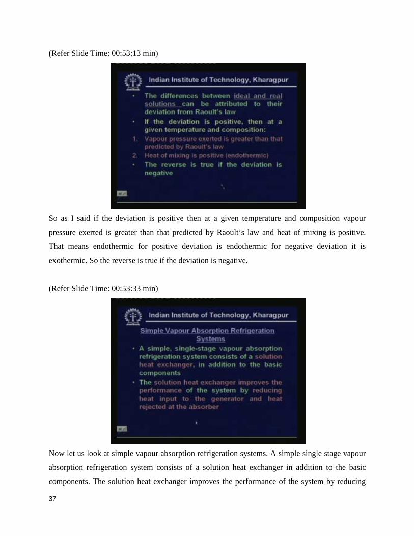
Obviously the real solutions are not ideal solutions real solution either contracts or expands upon
mixing. That means the specific volume V is not equal to xi one V one plus xi two V two and
either heat is evolved or heat is absorbed upon mixing. That means the mixing process is
exothermic either exothermic or endothermic. That means h is not equal to xi one h one plus xi
two h two but it is equal to xi one h one plus xi two h two plus delta h mix where delta h mix is
called as heat of mixing which could be positive or negative.
34

(Refer Slide Time: 00:51:17 min)
So the difference between ideal and real solutions can be attributed to their deviation from
Raoult's law okay. So let me show that.
(Refer Slide Time: 00:51:26 min)
So what I have shown here is the mole fraction of component two versus pressure when the mole
fraction is one zero here. That means you have pure component one and here you have
component two okay. That is why the pressure here is nothing but the saturation pressure of
component one and the pressure here is the saturated pressure of component two. Remember
that the temperature is constant here and if the solution behaves an ideal solution you have this
35

line. Because at any point pressure is simply equal tox one p one plus x two p two okay, that is
from your Raoult's law.
But the real solution will deviate either in the positive manner or in a negative manner if the
deviate from the positive, in a positive manner the actual vapour pressure will be larger than the
vapour pressure predicted by Raoult’s law okay. This is what you call as positive deviation and if
the deviate in a negative manner you find that the actual pressure is less than the pressure
predicted by the ideal solution okay. That is from the Raoult's law okay this you call it as
negative deviation from Raoult’s law okay. The same thing you can also shown.
(Refer Slide Time: 00:52:35 min)
Enthalpy chart what I have shown here is only for the negative deviation okay. So real solution
with negative deviation because this, what you encounter in vapour absorption refrigeration
systems. So for real solution with negative deviation you will find that delta h mix is negative
okay. That means heat is evolved during the mixing process that means this process is
exothermic okay. And this straight line gives a enthalpy of an ideal solution and the enthalpy of
real solution with negative deviation will be less than this because the delta h mix is negative
okay.
36
(Refer Slide Time: 00:53:13 min)
So as I said if the deviation is positive then at a given temperature and composition vapour
pressure exerted is greater than that predicted by Raoult’s law and heat of mixing is positive.
That means endothermic for positive deviation is endothermic for negative deviation it is
exothermic. So the reverse is true if the deviation is negative.
(Refer Slide Time: 00:53:33 min)
Now let us look at simple vapour absorption refrigeration systems. A simple single stage vapour
absorption refrigeration system consists of a solution heat exchanger in addition to the basic
components. The solution heat exchanger improves the performance of the system by reducing
37

the heat input to the generator and heat rejected at the absorber. That means only difference
between the earlier basic system and this simple practical system is in addition of one
component.
(Refer Slide Time: 00:53:58 min)
That is called as solution heat exchanger. So what we have done in this system is an extra
component is added is called a solution heat exchanger what is the function of this solution heat
exchanger. This solution heat exchanger pre heats okay, pre heats the solution that is going to the
generator by using the heat of the solution that is coming from the generator. So you can see that
there is heat exchange between the hot solution coming from the generator and the cold solution
that is going to the generator. So there is a heat exchange as a result Q g reduces this also reduces
okay.
So that is the function of the solution heat exchanger here rest of the components are same okay.
In fact this figure is shown as pressure versus temperature okay. The, so the you can also see the
respective pressures and temperatures on this diagram okay. This I will explain in detail when we
discuss the actual systems.
38

(Refer Slide Time: 00:54:51 min)
Now let me quickly look at the refrigerant absorbent combinations the desirable properties are
the refrigerant should exhibit high solubility with solution in the absorber it should be highly
soluble in the absorber. And the difference in boiling points should be large. So that only
refrigerant boils in the generator okay. This is another desirable point and heat of mixing should
be small okay of course point one and three are contradictor you cannot have both okay. Then
there should be no crystallization or solidification inside the system we will see what is
crystallization or solidification in the next class okay. Then the solution should be non corrosive
and it should exhibit good transport properties. That means thermal conductivity should be high
and viscosity should be low. So these are the desirable properties.
39

(Refer Slide Time: 00:55:34 min)
And based on these desirable properties there are two most commonly used refrigerant absorbent
pairs they are water lithium bromide for large capacity air conditioning applications and
ammonia water for large and small capacity refrigeration applications. So we will be discussing
these systems in details in next class one or two lectures okay. And there are also other
refrigerant absorbent pairs which are in at research level they are not yet commercialized okay.
So basically the most important pairs as far as the commercialized systems are concerned are
water lithium bromide and ammonia water pairs okay.
(Refer Slide Time: 00:56:09 min)
40

So let me quickly summarize what we have learned in this lesson. In this lesson basic concepts in
absorption refrigeration systems are introduced and simple vapour absorption refrigeration
systems are described and expressions for maximum COP of an ideal absorption system is
derived. And properties of ideal and real solutions are discussed and finally we have listed
desirable properties of refrigerant absorbent combinations okay. In the next lecture I shall discuss
lithium bromide water systems okay after that i shall discuss ammonia water systems okay.
Thank you.
41