Embed Size (px)
Citation preview

IDFDIDFFAir-cooled type Water-cooled type
IDUE
IDFE
Refrigerated Air Dryers
An air dryer removes the vapor from the moist compressed air delivered by thecompressor, and prevents it from causing the pneumatic equipment to fail.
Effects of moisture on equipment
Protect Pneumatic Equipment from Moisture!Protect Pneumatic Equipment from Moisture!
Decomposition of auto drain caused by rusting inside pipes
Generation of water dropletsMalfunctioning of valves and actuators caused by dripping grease
Standard inlet air temperature type Series IDF E/F/D
•Air flow capacity: Increased by up to 40% (SMC comparison)•Power consumption: Reduced by up to 40% (SMC comparison)•Improved corrosion resistance with the stainless steel heat exchanger∗
• Large size series• Tolerant of high temperature environment!
Top of its class in the industry for the large air-cooled typeAmbient temperature 45°C/Inlet air temperature 60°C(IDF100F to 150F)
• Energy saving designExhaust heat amount is reduced 25% to suppress the ambient temperature rise (air-cooled type) and reduce the facility water amount (water-cooled type) (IDF100F to 150F).
Model
IDF100FIDF125FIDF150FIDF190DIDF240D
IDF370D
100125150190240
370
R265 (2 1/2B) Flange
80 (3B) Flange
100 (4B) Flange
150 (6B) Flange
40°C0.7 MPa
35°C0.7 MPa
Model Rated inletcondition
Applicable aircompressor (kW)
IDF1EIDF2EIDF3EIDF4EIDF6EIDF8EIDF11EIDF15E1IDF22EIDF37EIDF55EIDF75E
0.751.52.23.75.57.5111522375575
Port size
Rc3/8
Rc1/2
Rc3/4
Rc1R1
R1 1/2
R2
35°C0.7 MPa
40°C0.7 MPa
High inlet air temperature type Series IDU E
The air dryers (CE or UL compliant) conforming to the international standards are separately available.∗IDF4E to 75E/IDU3E to 75E
IDU3EIDU4EIDU6EIDU8EIDU11EIDU15E1IDU22EIDU37EIDU55EIDU75E
2.23.75.57.5111522375575
Rc3/8Rc1/2
Rc3/4
Rc1R1
R1 1/2
R2
55°C0.7 MPa
∗IDF4E to 75E/IDU3E to 75E
Rated inletcondition
Applicable aircompressor (kW) Port size
Model Rated inletcondition
Applicable aircompressor (kW) Port size
Series IDF/IDUCAT.ES30-8I

New air dryer Conventional air dryer
Tolerant of high temperature environment (ambient temperature 45°C), Energy saving design!
Second re-heater helps the heat radiation of the condenser allow use at ambient temperature 45°C.
Air-cooled type can be used at ambient temperature 45°C.
Refrigerated Air Dryer
Series IDF100F/125F/150F
12 kW9kW
Condition: The IDF100F is operated with the rated condition of 60 Hz.
Exhaust heat from new air dryer 1
Exhaust heat fromexisting air dryer 2
Reduced by
25%
Exhaust heat from air dryer
Existing air dryer(Without second re-heater)
New air dryer(With second re-heater)
Air conditioner
1 2
F type
Indoor IndoorOutdoor
Air conditioner
Exha
ust h
eat
Exha
ust h
eat
Exhau
st heat
Exhau
st heat
Suppresses ambient temperature increase (air-cooled type)/ Reducesamount of facility water (water-cooled type)!Second re-heater reduces the load to the condenser, and reduces exhaust heat from air dryer by up to 25%. (comparison with other SMC products)
Energy saving design: Reduces exhaust heat from air dryer by up to 25%.
Reduced exhaust heat achieves downsizing and energy saving operation of the air conditioner!
Compressedair outlet
Compressed air afterremoving humidity
Compressedair outletSecond re-heater cools
the refrigerant and reduces theload to the condenser.
It cannot radiate heat if the ambient temperature
is excessive.
Second re-heater
RefrigerantRefrigerant
It is warmed by the second re-heater, preventing condensation of the piping on the outlet side.
Compressed air afterremoving humidity
Condenser Condenser
Compressor for refrigeration Compressor for refrigeration
Features 1

Dustproof filter
Electrical equipment
Facility water inlet
Facility water outlet
Facility water inlet
Facility water outlet
Temperature controlequipment
Series HRG
RightLeft
Installation space of theconventional type
Installation space of theIDF100F (Example: Installed
flat against the wall on the left)
Wall
Top
Right
Left
Rear
Avoid exhausting air onto adjacent equipment.
Series IDF100F/125F/150F
Maintenance
• Dustproof filter provided as a standard accessory
• Only access from frontside is required to check electrical equipment and dustproof filter.
Selection of layout
[Air-cooled type]Exhausting direction can be selected from four directions!!Auto drain tube can be connected in two directions, left or right.
Facility water piping port can be selected from two directions!!
[Water-cooled type]
Space saving
Either the left or right can be installed flat against a wall! Note)
Installation space can be reduced by up to 1.5 m2!!
Leave at least 600 mm on the sides indicated with .
Note) For air-cooled type, leave a space of at least 600 mm between the heat exhausting surface and the wall.For water-cooled type, leave a space at least 600 mm between the facility water piping side and the wall.
Features 2

P.5 to 8
P.9 to 11
P.12 to 19
PageModel RefrigerantApplicable air
compressor (kW)50 Hz
0.1
0.2
0.32
0.52
0.75
1.22
1.65
2.8
3.9
5.7
8.4
11.0
16.0
20.1
25.0
32.0
43.0
54.0
60 Hz
Air flow capacity (m3/min [ANR])
IDF1E
IDF2E
IDF3E
IDF4E
IDF6E
IDF8E
IDF11E
IDF15E1
IDF22E
IDF37E
IDF55E
IDF75E
IDF100F
IDF125F
IDF150F
IDF190D
IDF240D
IDF370D
Rated inlet condition
35°C0.7 MPa
40°C0.7 MPa
35°C0.7 MPa
0.12
0.235
0.37
0.57
0.82
1.32
1.82
3.1
4.3
6.1
9.8
12.4
18.8
23.7
30.0
38.0
50.0
65.0
0.75
1.5
2.2
3.7
5.5
7.5
11
15
22
37
55
75
100
125
150
190
240
370
Rc3/8
Rc1/2
Rc3/4
Rc1
R1
R1 1/2
R2
65(2 1/2B) Flange
80(3B) Flange
100(4B) Flange
150(6B) Flange
Port size
R134a (HFC)
R407C (HFC)
P.20 to 22
P.23 to 25
Page50 Hz
0.32
0.52
0.75
1.1
1.5
2.6
3.9
5.7
8.4
11.0
60 Hz
IDU3E
IDU4E
IDU6E
IDU8E
IDU11E
IDU15E1
IDU22E
IDU37E
IDU55E
IDU75E
55°C0.7 MPa
0.37
0.57
0.82
1.2
1.7
2.8
4.3
6.1
9.8
12.5
2.2
3.7
5.5
7.5
11
15
22
37
55
75
Rc3/8
Rc1/2
Rc3/4
Rc1
R1
R1 1/2
R2
R134a (HFC)
R407C (HFC)
Complies with CFC restrictions
Refrigerated Air Dryers
Series IDFE/F/D Rated inlet air temperature: 35, 40°C
Series IDUE Rated inlet air temperature: 55°C
Standard inlet air temperature type
High inlet air temperature type
Series IDF/IDU
INDEXINDEX
∗ Refer to the WEB catalog or Best Pneumatics No.5 for air dryer models conforming to international standards (CE and UL).
Larg
e si
ze s
erie
s
Model RefrigerantApplicable air
compressor (kW)
Air flow capacity (m3/min [ANR])Rated inlet condition
Port size
1
2. Options
P.26, 27
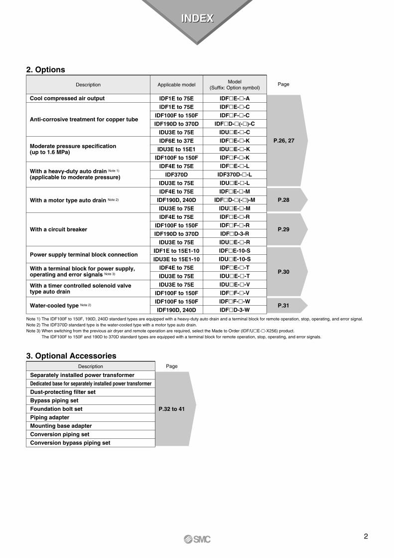
P.28
P.29
P.30
P.31
PageDescription
Cool compressed air output
Anti-corrosive treatment for copper tube
Moderate pressure specification(up to 1.6 MPa)
With a heavy-duty auto drain Note 1) (applicable to moderate pressure)
With a motor type auto drain Note 2)
With a circuit breaker
Power supply terminal block connection
With a terminal block for power supply, operating and error signals Note 3)
With a timer controlled solenoid valve type auto drain
Water-cooled type Note 2)
Applicable modelModel
(Suffix: Option symbol)
IDF1E to 75E
IDF1E to 75E
IDF100F to 150F
IDF190D to 370D
IDU3E to 75E
IDF6E to 37E
IDU3E to 15E1
IDF100F to 150F
IDF4E to 75E
IDF370D
IDU3E to 75E
IDF4E to 75E
IDF190D, 240D
IDU3E to 75E
IDF4E to 75E
IDF100F to 150F
IDF190D to 370D
IDU3E to 75E
IDF1E to 15E1-10
IDU3E to 15E1-10
IDF4E to 75E
IDU3E to 75E
IDU3E to 75E
IDF100F to 150F
IDF100F to 150F
IDF190D, 240D
IDFE--A
IDFE--C
IDFF--C
IDFD-(-)-C
IDUE--C
IDFE--K
IDUE--K
IDFF--K
IDFE--L
IDF370D--L
IDUE--L
IDFE--M
IDFD-(-)-M
IDUE--M
IDFE--R
IDFF--R
IDFD-3-R
IDUE--R
IDFE-10-S
IDUE-10-S
IDFE--T
IDUE--T
IDUE--V
IDFF--V
IDFF--W
IDFD-3-W
3. Optional Accessories
P.32 to 41
PageDescription
Separately installed power transformer
Dedicated base for separately installed power transformer
Dust-protecting filter set
Bypass piping set
Foundation bolt set
Piping adapter
Mounting base adapter
Conversion piping set
Conversion bypass piping set
INDEXINDEX
Note 1) The IDF100F to 150F, 190D, 240D standard types are equipped with a heavy-duty auto drain and a terminal block for remote operation, stop, operating, and error signal.Note 2) The IDF370D standard type is the water-cooled type with a motor type auto drain. Note 3) When switching from the previous air dryer and remote operation are required, select the Made to Order (IDF/UE--X256) product.
The IDF100F to 150F and 190D to 370D standard types are equipped with a terminal block for remote operation, stop, operating, and error signals.
2

The corrected air flow capacity, which considers the user’s operating conditions, is required for selecting air dryer. Select using the following procedures.
IDF Selection Example IDU Selection ExampleRead the correction factors.
2
Calculate the correctedair flow capacity.
Obtain the corrected air flowcapacity from the following formula.Corrected air flow capacity = Air flow rate ÷ (Correction factor A x B x C x D)
Corrected air flow capacity = 0.3 m3/min ÷ (0.82 x 0.96 x 1 x 0.88)
= 0.43 m3/min
Corrected air flow capacity = 0.4 m3/min ÷ (0.95 x 0.93 x 1 x 0.88)
= 0.51 m3/min
4
Select the model.Select the model with air flow capacitywhich exceeds the corrected air flowcapacity from the specification table.(For air flow capacity, refer to the dataE on page 4.)
According to the corrected air flow capacity of 0.43 m3/min, the IDF4E will be selected which air flowcapacity is 0.52 m3/min at 50 Hz.
According to the corrected air flow capacity of 0.51 m3/min, the IDU4E will be selected which air flowcapacity is 0.57 m3/min at 60 Hz.
5
Options Refer to pages 26 to 31. Refer to pages 26 to 31.
Refer to pages 5, 9, 12, 17.
Refer to pages 32 to 41.
Refer to pages 20 and 23.
6Finalize the modelnumber.7Select the optionalaccessories.8
Check the coefficient. Correction factor = 0.82 x 0.96 x 1 x 0.88 = 0.69Max. coefficient value is 1.5. Correction factor is 1.5when the calculation result is 1.5 or greater.
Correction factor = 0.95 x 0.93 x 1 x 0.88 = 0.78Max. coefficient value is 1.5. Correction factor is 1.5when the calculation result is 1.5 or greater.
3
Select the IDF or IDU. Select the IDF or IDU from inlet air temperature used. • Inlet air temperature 5 to 50°C ····· IDF (For IDF100F to 150F, up to 60°C is allowed.)• Inlet air temperature 50 to 80°C ····· IDU
1
Correction factor Note)Data symbol
40°C
35°C
10°C
0.5 MPa
0.3 m3/min
50 Hz
A
B
C
D
—
—
0.82
0.96
1
0.88
—
—
Inlet air temperature
Ambient temperature
Outlet air pressure dew point
Inlet air pressure
Air flow rate
Power supply frequency
Condition
Note) Values obtained from “Correction Factors” on page 4.
Correction factor Note)Data symbol
60°C
35°C
10°C
0.5 MPa
0.4 m3/min
60 Hz
A
B
C
D
—
—
0.95
0.93
1
0.88
—
—
Inlet air temperature
Ambient temperature
Outlet air pressure dew point
Inlet air pressure
Air flow rate
Power supply frequency
Condition
Note) Values obtained from “Correction Factors” on page 4.
Series IDF/IDU
Obtain the correction factors A to D suitable for your operating condition from the table on the next page.
3
Model Selection

Data A: Inlet Air Temperature
Correction Factors
Data C: Outlet Air Pressure Dew Point
Data B: Ambient Temperature Note)
Data D: Inlet Air Pressure
Data E: Air Flow Capacity
Series IDFIDF1E to 75E, 190D to 370D
Series IDUIDU3E to IDU37E
Correctionfactor
0.550.7 1 1.3
35
1015
Outlet air pressure dew point (°C)
Correctionfactor
0.550.7 1 1.3
35
1015
Outlet air pressure dew point (°C)
IDU55E, 75ECorrection
factor
0.530.671 1.30
35
1015
Outlet air pressure dew point (°C)
IDF100F to 150FCorrection
factor
0.550.7 1 1.4
35
1015
Outlet air pressure dew point (°C)
Series IDFModel IDF1E
0.100.12
IDF2E0.20 0.235
IDF3E0.320.37
IDF4E0.520.57
IDF6E0.750.82
IDF8E1.221.32
IDF11E1.651.82
IDF15E12.83.1
IDF22E3.94.3
IDF37E5.76.1
IDF55E8.49.8
IDF75E11.012.4
Air flow capacitym3/min (ANR)
50 Hz60 Hz
Series IDUModel IDU3E
0.320.37
IDU4E0.520.57
IDU6E0.750.82
IDU8E1.11.2
IDU11E1.51.7
IDU15E12.62.8
IDU22E3.94.3
IDU37E5.76.1
IDU55E8.49.8
IDU75E11.012.5
Air flow capacitym3/min (ANR)
50 Hz60 Hz
Model IDF125F20.123.7
IDF100F16.018.8
Air flow capacitym3/min (ANR)
50 Hz60 Hz
IDF150F25.030.0
IDF190D32.038.0
IDF240D43.050.0
IDF370D54.065.0
Note) In the case of the option A (cool compressed air output), the air flow capacity is different. Refer to page 26 for details.
Series IDFIDF1E to 37E
Inlet air temp. (°C)
Correctionfactor
1.3 1 0.820.680.57
5 to 3035404550
IDF55E, 75E, 190D to 240DInlet air
temp. (°C)Correction
factor
1.351.251 0.8 0.6
5 to 3035404550
IDF100F to 150FInlet air
temp. (°C)Correction
factor
1.411.211 0.920.750.630.53
5 to 30354045505560
Series IDUIDU3E to IDU37E
Inlet air temp. (°C)
Correctionfactor
1.151.071 0.950.9 0.860.820.79
5 to 4550556065707580
IDF370DInlet air
temp. (°C)Correction
factor
1.251.000.830.700.60
5 to 3035404550
IDU55E, 75EInlet air
temp. (°C)Correction
factor
1.211.101 0.870.760.740.720.70
5 to 4550556065707580
IDF100F to 150FAmbient temp. (°C) Correction factor
1.061.021 0.990.980.92
2 to 253032354045
IDF190D to 240DAmbient temp. (°C) Correction factor
1.101.051 0.950.90
2 to 2530323540
IDU55E, 75EAmbient temp. (°C) Correction factor
1.251.111 0.900.63
2 to 2530323540
Series IDFIDF1E to 75EAmbient temp. (°C) Correction factor
1.141.041 0.960.9
2 to 2530323540
Series IDUIDU3E to IDU37EAmbient temp. (°C) Correction factor
1.2 1.041 0.930.84
2 to 2530323540
Series IDFIDF1E to 75EInlet air pressure
(MPa)
Correctionfactor0.620.720.810.880.951 1.061.111.16
0.20.30.40.50.60.70.80.9
1 to 1.6
IDF190D to 370DInlet air pressure
(MPa)
Correctionfactor0.680.770.840.900.951 1.031.061.08
0.20.30.40.50.60.70.80.91.0
IDF100F to 150FInlet air pressure
(MPa)
Correctionfactor0.840.870.9 0.930.961 1.031.061.09
0.20.30.40.50.60.70.80.9
1 to 1.6
Series IDUIDU3E to 37E
Inlet air pressure
(MPa)
Correctionfactor0.620.720.810.880.951 1.061.111.16
0.20.30.40.50.60.70.80.9
1 to 1.6
IDU55E, 75EInlet air pressure
(MPa)
Correctionfactor0.620.690.770.850.931 1.081.161.23
0.20.30.40.50.60.70.80.9
1 to 1.6
Note) For the water-cooled type, the correction factor is determined to “1” in an ambient temperature range of 2 to 45°C.
4
Model Selection Series IDF/IDU

How to Order
IDF 8E 10
SizeSymbol
1E2E3E4E6E8E11E15E1
Air compressor size Note)
Voltage
Single-phase100 VAC (50Hz)100/110 VAC (60Hz)
10
Single-phase200 VAC (50Hz)200/220 VAC (60Hz)
20
Symbol VoltageApplicable size
1E
—
2E
—
3E
4E
6E
8E
11E
15E1
NilACKLMRST
Note) Note that the above values are for reference only. Check the actual compressor capacity.
Note 1) Enter alphabetically when multiple options are combined.However, the following combinations are not possible.· R and S (Because S function is also included in R.)· S and T (Because S function is also included in T.)· The combination of K, L and M is not possible because an auto drain can only be attached to a single option.
Note 2) Voltage symbol 20 (200 VAC) is the terminal block connection as standard. The option S cannot be chosen.Voltage symbol 10 (100 VAC) is the power cable with plug as standard.
Note 3) To users who are considering switching from the previous air dryer:
Note 4) Refer to pages 26 to 30 for further information on options.
Refrigerant R134a (HFC)
1E, 2E, 3E, 4E, 6E, 8E, 11E, 15E1(Inlet air temperature: 35°C, Outlet air pressure dew point: 10°C)
Standard Inlet Air Temperature
Option
1E
2E
3E
4E
6E
8E
11E
15E1
Symbol Note 1) Nil
Size
DescriptionNone
A
Coolcompressedair output
R
With acircuit
breaker
—
—
—
TWith a terminalblock for power
supply, operating and
error signals Note 3)
—
—
—
SPower supplyterminal block
connection(Voltage symbol
10 only) Note 2)
C
Anti-corrosivetreatment forcopper tube
LWith a heavy-duty
auto drain(applicable to
moderatepressure)
—
—
—
M
With amotor typeauto drain
—
—
—
K
—
—
—
—
Auto drain bowl: Metal bowl with level gauge
Moderate pressurespecification
When switching from the previous air dryer and remote operation are required, select the Made to Order (IDFE--X256) product.
Series IDF E
0.75 kW
1.5 kW
2.2 kW
3.7 kW
5.5 kW
7.5 kW
11 kW
15 kW
5

IDF1E IDF2E, IDF3E
Refrigeratedair dryer
Auto drain
Symbol
Humid, hot air coming into the air dryer will be cooled down by a cooler (heat exchanger). Water condensed at this time will be removed from the air by a drain separator (auto drain) and drained out automatically. Air separated from the water will be heated by a re-heater (heat exchanger) to obtain the dried air, which goes through to the outlet side.
Drain separator
Drain outlet
Compressed air inletCompressedair outlet
Pressure switch
Compressor forrefrigeration
Cooler
Re-heater
Evaporation thermometer
Condenser
Volume control valve
Capillary tubeFan motor
Capillary tube
Compressor forrefrigerationPressure switch
Drain separator
Drain outlet
Compressed air inlet Compressed air outlet
Evaporation thermometer
Re-heater
Volume control valve
Cooler
Fan motor
Condenser
Note 1) Air flow capacity under the standard condition (ANR) [atmospheric pressure 20°C, relative humidity 65%]Note 2) Air flow capacity converted by the compressor intake condition [atmospheric pressure 32°C, relative humidity 75%]Note 3) The operation range does not guarantee the use with normal air flow capacity.Note 4) Select the air dryer model according to “Model Selection” (pages 3, 4) for models beyond the rated specifications.Note 5) When selecting a power supply voltage, refer to “How to Order” on page 5.Note 6) These values are reference values under rated conditions, and are not guaranteed. Do not use these values for the thermal set values etc.Note 7) Product other than the option R is not equipped with a circuit breaker. Purchase an appropriate circuit breaker separately.
Note 8) The part number for the auto drain components only excluding the body part.Body part replacement is not possible.
Auto drain
Body
Air flowcapacity(m3/min)
Standard condition(ANR) Note 1)
Compressor intake condition Note 2)
Model
Specifications IDF1E
0.10
0.12
0.11
0.13
IDF2E
0.20
0.235
0.21
0.25
IDF3E
0.32
0.37
0.34
0.39
IDF4E
0.52
0.57
0.55
0.61
IDF6E
0.75
0.82
0.8
0.87
IDF8E
1.22
1.32
1.3
1.4
IDF11E
1.65
1.82
1.75
1.93
IDF15E1
2.8
3.1
3.0
3.3
180/202
—
2.4/2.5
—
180/202
—
2.4/2.5
—
180/202
2.4/2.5
1.2/1.3
180/202
2.4/2.5
1.2/1.3
180/202
2.4/2.5
1.2/1.3
208/236
3.0/3.1
1.5/1.5
385/440
5.7/5.7
3.4/3.0
10 (100 VAC)10 (200 VAC)
420/480
4.3/4.6
3.4/3.1
Body panel: White 1Base: Gray 2
Standard inlet air temperature
Applicable air compressor output (Reference) For screw type
Single-phase: 100 VAC (50 Hz), 100/110 VAC (60 Hz) Note 5)
Single-phase: 200 VAC (50 Hz), 200/220 VAC (60 Hz)
50 Hz
60 Hz
50 Hz
60 Hz
Compressed air
5 to 50
0.15 to 1.0
2 to 40 (Relative humidity 85% or less)
0.7
35
32
10
Fluid
Inlet air temperature
Inlet air pressure
Ambient temperature (humidity)
Inlet air pressure
Inlet air temperature
Ambient temperature
Outlet air pressure dew point
Power supply voltage(frequency) Note 5)
Condenser
Refrigerant
Auto drain
Port size
Weight
Coating color
(°C)
(MPa)
(°C)
(MPa)
(°C)
(°C)
(°C)
Single-phase 100 V
Single-phase 200 V
Single-phase 100 V
Single-phase 200 V
(A)
(kg)
(kW)
Operating current 50/60 Hz Note 6) (A)
Power consumption 50/60 Hz Note 6) (W)
10 (100 VAC), 5 (200 VAC)
Air-cooled
R134a (HFC)
16
0.75
Rc3/8
17
1.5
18
2.2
Rc1/2
22
3.7
23
5.5
Rc3/4
27
7.5
Float type(Normally open)
28
11
Float type(Normally closed)
Rc1
46
15
Standard Specifications
Construction (Air/Refrigerant Circuit)
IDF4E, IDF6EIDF8E, IDF11E, IDF15E1
Drain outletEvaporation thermometer
Drain separatorHeat exchanger
Capillary tube
Compressedair outlet
Pressure switch
Compressed air inlet
Volumecontrol valve
Compressor forrefrigeration
Condenser Fan motor
Replacement PartsModel
Auto drain replacement parts no. Note 8)IDF1EAD37
IDF2E IDF3EAD38
IDF4E IDF6EAD48
IDF8E IDF11E IDF15E1
Opera
ting r
ange
Note
3)R
ated
co
nd
itio
ns
Not
e 4)
Ele
ctr
icsp
ecif
icati
on
s
Applicable circuitbreaker capacity Note 7)
(sensitivity current 30 mA)
6
Refrigerated Air Dryer Series IDF E

IDF1E to 3E
IDF4E to 11E
Ventilationdirection
Ventilationdirection
Evaporation thermometer
Illuminated switch
Drain tube
(O.D. ø10, lengthapprox. 0.8 m)
Compressed air outlet
Port sizeCompressed air inlet
Port size
[200 VAC specification]Power cable outlet (ø17)
Ventilationair inlet
[200 VAC specification]Terminal block
IDF3E-20 only
A
L K
N M
B
Q
P
E D
FG
H
J
C
[100 VAC specification]Power cable (Length: approx.1.9 m)
[100 VAC specification]Power cable (Length:approx.1.9 m)
Model
IDF1EIDF2EIDF3EIDF4EIDF6EIDF8EIDF11E
Port size
(mm)
Rc3/8
A
226
B
410
453
455
485
C
413
473
498
568
D69
51
67
31
E101
125
42
F270
232
304
283
355
G 32
138
33
80
H
—
73
230
J
—
31
32
K
38
36
15
L
150
154
240
M21
24
21
80
N330
327
330
275
300
P
240
284
Q
15
13
15270
Rc1/2
Rc3/4
Compressed air inlet
Compressed air outlet
Port size
Port size
[200 VAC specification]Terminal block
[200 VAC specification]
4 x ø13
Ventilationair outlet
Ventilationdirection
Ventilationdirection
Drain tube
Evaporation thermometer
Illuminated switch
Power cable outlet (ø17)
FG
E D
J HMN
A
KL
C
Q
P
B
Dimensions
Dimensions
(O.D. ø10, lengthapprox. 0.8 m)
7
Series IDF E

Dimensions
IDF15E1
380
60316
578
101
4 x ø13
300
270
314
15
Evaporation thermometer
Illuminated switch
Ventilationdirection
Ventilationdirection
(O.D. ø10, lengthapprox. 0.8 m)
Drain tube
43
258
54 41
8739
6
Power cable outlet (ø17)
[200 VAC specification]
Terminal block[200 VAC specification]
Rc1Compressed air outlet
Rc1Compressed air inlet
Power cable (Length: approx.1.9 m)[100 VAC specification]
Ventilation air outlet
8
Refrigerated Air Dryer Series IDF E

How to Order
55EIDF 30
SizeSymbol
22 kW
37 kW
55 kW
75 kW
22E37E55E75E
Air compressor size Note)
Voltage
Option
Single-phase200 VAC (50 Hz)200/220 VAC (60 Hz)
20
Three-phase200 VAC (50 Hz)200/220 VAC (60 Hz)
30
Symbol VoltageApplicable size
22E 37E
—
55E
—
75E
22E
37E
55E
75E
Symbol Note 1) Nil
Size
DescriptionNone
A
Cool compressedair output
C
Anti-corrosivetreatment forcopper tube
K
—
—
L
R
M
T
NilACKLMRT
Note 1) Enter alphabetically when multiple options are combined.However, the following combinations are not possible.· The combination of K, L and M is not possible because an auto drain can only be attached to a single option.
Note 2) Select the option L for the 55E and 75E which need moderate pressure.Note 3) To users who are considering switching from the previous air dryer:
Note 4) Refer to pages 26 to 30 for further information on options.
Note) Note that the above values are for reference only. Check the actual compressor capacity.
Note 2)
Note 2)
When switching from the previous air dryer and remote operation are required, select the Made to Order (IDFE--X256) product.
Refrigerant R407C (HFC)
22E, 37E, 55E, 75E(Inlet air temperature: 35°C (22E, 37E), 40°C (55E, 75E), Outlet air pressure dew point: 10°C)
Standard Inlet Air Temperature
Series IDF E
With acircuit
breaker
With a terminalblock for power
supply, operating and error
signals Note 3)
With a heavy-dutyauto drain
(applicable tomoderatepressure)
With amotor typeauto drain
Auto drain bowl: Metalbowl with level gauge
Moderate pressurespecification
9

Humid, hot air coming into the air dryer will be cooled down by a cooler re-heater (heat exchanger). Water condensed at this time will be removed from the air by an auto drain and drained out automatically. Air separated from the water will be heated by a cooler re-heater (heat exchanger) to obtain the dried air, which goes through to the outlet side.
IDF22E, IDF37E, IDF55E, IDF75E
Note 1) Air flow capacity under the standard condition (ANR) [atmospheric pressure 20°C, relative humidity 65%]Note 2) Air flow capacity converted by the compressor intake condition [atmospheric pressure 32°C, relative humidity 75%]Note 3) The operation range does not guarantee the use with normal air flow capacity.Note 4) Select the air dryer model according to “Model Selection” (pages 3, 4) for models beyond the rated specifications.Note 5) When selecting a power supply voltage, refer to “How to Order” on page 9.Note 6) These values are reference values under rated conditions, and are not guaranteed. Do not use these values for the thermal set values etc.Note 7) Product other than the option R is not equipped with a circuit breaker. Purchase an appropriate circuit breaker separately.
Note 8) The part number for the auto drain components only excluding the body part.Body part replacement is not possible.
Standard Specifications
Construction (Air/Refrigerant Circuit)
Model
Specifications IDF22E
3.9
4.3
4.1
4.6
810/940
850/1070
4.3/4.7
3.3/3.5
810/940
850/1070
4.3/4.7
3.3/3.5
10 (200 VAC)
Air-cooled
R407C (HFC)
Float type (Normally open)
R1
54
22 37 55 75
R1 1/2
62
R2
116100
—
1300/1700
—
5.0/5.4
—
2000/2500
—
7.2/8.0
15 (200 VAC)
IDF37E
5.7
6.1
6.1
6.5
Compressed air
5 to 50
0.15 to 1.0
2 to 40 (Relative humidity 85% or less)
0.7
32
10
35
Single-phase/Three-phase: 200 VAC (50 Hz) Note 5)
Single-phase/Three-phase: 200/220 VAC (60 Hz)Three-phase: 200 VAC (50 Hz)Three-phase: 200/220 VAC (60 Hz)
Body panel: White 1Base: Gray 2
40
IDF55E
8.4
9.8
8.9
10.4
IDF75E
11.0
12.4
11.7
13.2
Standard inlet air temperature
Applicable air compressor output(Reference) For screw type
50 Hz
60 Hz
50 Hz
60 Hz
Fluid
Inlet air temperature
Inlet air pressure
Ambient temperature (humidity)
Inlet air pressure
Inlet air temperature
Ambient temperature
Outlet air pressure dew point
Condenser
Refrigerant
Auto drain
Port size
Weight
Coating color
(°C)
(MPa)
(°C)
(MPa)
(°C)
(°C)
(°C)
Single-phase 200 V
Three-phase 200 V
Single-phase 200 V
Three-phase 200 V
(A)
(kg)
(kW)
Operating current (A) 50/60 Hz Note 6)
Power consumption (W) 50/60 Hz Note 6)
Replacement PartsModel
Auto drain replacement parts no. Note 8)IDF22E
AD48IDF37E IDF55E IDF75E
Pressure switch
Compressed air inletCompressed air outlet
Auto drain
Drain outletVolume control valve
Accumulator(IDF22E, 37E, 55E only) Condenser
Capillary tube
Cooler re-heater(Heat exchanger)
Ball valve
Fan motorHigh pressure switch(IDF55E, 75E only)
Compressor for refrigeration
Evaporation thermometer
Refrigeratedair dryer
Auto drain
Symbol
Auto drain
Body
Air flowcapacity(m3/min)
Standard condition(ANR) Note 1)
Compressor intakecondition Note 2)
Power supply voltage(frequency) Note 5)
Opera
ting r
ange
Note
3)R
ated
co
nd
itio
ns
Not
e 4)
Ele
ctr
icsp
ecif
icati
on
s
Applicable circuit breaker capacity Note 7)
(sensitivity current 30 mA)
10
Refrigerated Air Dryer Series IDF E

Dimensions
IDF22E, IDF37E
IDF55E, IDF75E
F
D
H N M
C
E
B
Port sizeCompressed air inlet
Port size
Compressed air outlet
(Electric wire diameter ø9 to 11)[opposite side]
Auto drain Power cable holder 4 x ø13
G
A
K
P
L
Ball valve
Ventilationdirection
Ventilation direction
Terminal block
Evaporation thermometer
Illuminated switch
JVentilation air outlet
(O.D. ø10, length approx. 0.8 m)
Drain tube
Model
IDF22EIDF37EIDF55EIDF75E
Port size
R1
R1 1/2
R2
B775
855
855
A
290
470
C
623
800
900
D
134
128
E
405
455
F
698
868
968
G
93
110
H
46
36
J
25
50
K
13
13
L
314
500
M
85
75
N600
680
700
P
340
526
Q
—
250
R
—
519
(mm)
Ball valve
Ventilation direction
(O.D. ø10, length approx. 1 m)
(Electric wire diameter ø9 to 11) [opposite side]
Ventilation air outlet
Power cable holder
Drain tube
Evaporation thermometer
R
A
QGB
E D
FC
PL K
J
HMN
Auto drain
Ventilation direction
Terminal block
Illuminated switch
Compressed air inletPort size
Compressed air outletPort size
4 x ø13
Dimensions
11
Series IDF E

How to Order
IDF 100 F 30Size
Size Air compressor size Note)
100 kW
125 kW
150 kW
100125150
Voltage
Option
Three-phase200 VAC (50 Hz)200/220 VAC (60 Hz)
30
Symbol Voltage
Note) Note that the above values are for reference only. Check the actual compressor capacity.
Note 1) Enter alphabetically when multiple options are combined.
Note 2) A terminal block for remote operation, stop, operating, and error signals is provided as a standard accessory.
Note) The combination of 1, 2 and 3 is not available. (Heat exhausting face can be specified on one side only.)
NilBCKPRV
Nil123
Symbol Note 1) Description
None
Anti-corrosive treatment for copper tube
Moderate pressure specification
With a metal name plate
With a circuit breaker
With a timer controlled solenoid valve type auto drain
NilCKPRV
Heat exhausting directionSymbol Description
Heat exhaust from the rear
Heat exhaust from the right Note)
Heat exhaust from the left Note)
Heat exhaust from the top Note)
Nil123
Air-cooled
Top: 3
Right: 1
Left: 2
Rear: Nil
IDF 100 F 30Size
Size Air compressor size Note)
100 kW
125 kW
150 kW
100125150
Voltage
Option
Three-phase200 VAC (50 Hz)200/220 VAC (60 Hz)
30
Symbol Voltage
W
Cooling method
Water-cooled condenserWSymbol Cooling method
Note) Note that the above values are for ref-erence only. Check the actual compres-sor capacity.
Note) The combination of 4 and 5 is not available. (Piping direction can be specified on one side only.)
NilCDKPRV
45
Symbol Note 1) Description
None
Anti-corrosive treatment for copper tube
Moderate pressure specification (1.6 MPa)
With a metal name plate
With a circuit breaker
With a timer controlled solenoid valve type auto drain
NilCKPRV
Piping directionSymbol Description
Facility water piping direction: Right Note)
Facility water piping direction: Left Note)
45
Water-cooled
Right: 4
Left: 5
Refrigerant R407C (HFC)
Applicable Compressor Size: 100 kW, 125 kW, 150 kW(Max. inlet air temperature: 60°C, Max. ambient temperature: 45°C)
Series IDF100F/125F/150F
Note 1) Enter alphabetically when multiple options are com-bined.
Note 2) A terminal block for remote operation, stop, operating, and error signals is provided as a standard accessory.
12

Refrigerated air dryer
Auto drain
Symbol
Pressure switch
High pressure switch
Condensed pressure gauge
Capillary tube
Evaporation thermometer
Low pressure switch
Filter dryer
Compressor for refrigeration
Volume control valve
Compressed air outlet
Condenser Fan motor Air pressure gauge
Compressed air inlet
Cooler re-heater
Ball valve
Auto drain
Drain outlet
Second re-heater
Housing(Use existing equipment.)
Exhaust mechanism replacement kit
Compressed air
5 to 60
0.15 to 1.0
2 to 45 (Relative humidity 85% or less)
0.7
40
32
10
37
Three-phase 200 VAC (50 Hz), 200/220 VAC (60 Hz)
30
R407C (HFC)
Heavy-duty auto drain (Normally open)
Hot and humid air entering the air dryer is cooled down by the cooler re-heater (heat exchanger). The moisture which is condensed and separated is automatically exhausted by the auto drain. The air which has had its moisture removed is heated in two stages by the re-heater (heat exchanger) in the cooler re-heater and by the second re-heater, and is supplied to the outlet side as warm and dry air.
Compressed air from which drainage has been exhausted ex-changes heat with refrigerant which has been compressed by the compressor for refrigeration, to give the following effects:1. The outlet air temperature increases, preventing condensa-
tion of the piping on the outlet side.2. The amount of heat exhausted from the condenser is re-
duced.3. Energy saving operation of the air dryer is achieved by re-
ducing the amount of heat exhausted from the condenser.
IDF100F, IDF125F, IDF150F
Standard Specifications: Air-cooled Type
Construction (Air/Refrigerant Circuit)
Air flow capacity(m3/min)
Standard condition (ANR) Note 1)
Compressor intake condition Note 2)
ModelSpecifications IDF100F-30 IDF125F-30 IDF150F-30
50 Hz
60 Hz
50 Hz
60 Hz
Fluid
Inlet air temperature
Inlet air pressure
Ambient temperature (humidity)
Inlet air pressure
Inlet air temperature
Ambient temperature
Outlet air pressure dew point
Exhaust heat from condenser (50/60 Hz)
Air dryer outlet air temperature
Power supply voltage (frequency)
Power consumption (kW) 50/60 Hz Note 5)
Operating current (A) 50/60 Hz
Refrigerant
Auto drain
Port size
Weight
Coating color
Applicable air compressor output (Reference) For screw type
(°C)
(MPa)
(°C)
(MPa)
(°C)
(°C)
(°C)
(kW)
(°C)
(A)
(kg)
(kW)
Replacement PartsAir dryer model
Heavy-duty auto drain replacement part no. Note 7)
Dustproof filter set for condenser
IDF100F
IDF-FL219 IDF-FL220
IDF125F IDF150FADH-E400
Body panel: White 1Base: Gray 2
Note 1) Air flow capacity under the standard condition (ANR) [atmospheric pressure 20°C, relative humidity 65%]Note 2) Air flow capacity converted by the compressor intake condition [atmospheric pressure 32°C]Note 3) The operation range does not guarantee the use with normal air flow capacity.Note 4) Select the air dryer model according to “Model Selection” (pages 3, 4) for models beyond the rated specifications.Note 5) These values are reference values under rated conditions, and are not guaranteed. Do not use these val-
ues for the thermal set values etc.Note 6) Product other than the option R is not equipped with a circuit breaker.
Purchase an appropriate circuit breaker separately.
Note 7) Part number of only the exhaust mechanism replacement kit excluding the housing
Note 8) A terminal block for remote operation, stop, operating, and error signal is pro-vided as a standard accessory.
Second re-heater
16
18.8
17
20
20.1
23.7
21
25
25
30
27
32
8.0/9.0
2.9/3.5
10.5/11.5
R2
245
100 125 150
JIS flange 65A 10K
270
JIS flange 80A 10K
350
4.0/4.7
15.4/15.6
4.0/4.8
15.7/16.0
10.0/11.5 12.0/15.0
Opera
ting r
ange
Note
3)R
ated
co
nd
itio
ns
Not
e 4)
Electr
icsp
ecific
ation
s
Applicable circuit breaker capacity Note 6)
(sensitivity current 30 mA)
13
Series IDF100F/125F/150F

Refrigerated air dryer
Auto drain
Symbol
Condenser
High pressure switch
Condensed pressure gauge
Drain outlet
Compressed air outlet
Compressed air inlet
Compressor for refrigeration
Evaporation thermometer
Capillary tube
Volume control valve
Filter dryer
Air pressure gauge
Low pressure switch
Facility water outlet
Pressure type water regulating valve
Facility water inlet
Ball valve
Auto drain
Ball valve
Cooler re-heater
Y-shaped strainer
IDF100F-WIDF125F-WIDF150F-W
Housing
Exhaust mechanism replacement kit
(Use existing equipment.)
Second re-heater
Standard Specifications: Water-cooled Type
Construction (Air/Refrigerant Circuit)
Replacement PartsAir dryer model
Heavy-duty auto drain replacement part no. Note 9)
Facility water piping strainer
IDF100F-W
IDF-S0406
IDF125F-WADH-E400
IDF150F-W
IDF-S0418
Note 1) Air flow capacity under the standard condition (ANR) [atmospheric pressure 20°C, relative humidity 65%]Note 2) Air flow capacity converted by the compressor intake condition [atmospheric pressure 32°C]Note 3) The operation range does not guarantee the use with normal air flow capacity. Select the air dryer model
according to “Model Selection” (pages 3, 4) for models beyond the rated specifications.Note 4) The facility water flow rate that satisfies the rated conditions with a facility water inlet temperature of 32
and an output temperature of 37°C ( t = 5°C)Note 5) These values are obtained under rated conditions with a rated facility water flow rate and a facility water inlet pressure of 0.2 MPa.Note 6) These values are obtained under rated conditions (1 RT = 4.535 kW).Note 7) These values are reference values under rated conditions, and are not guaranteed. Do not use these values for the thermal set values etc.Note 8) Product other than the option R is not equipped with a circuit breaker.
Purchase an appropriate circuit breaker separately.
Note 9) Part number of only the exhaust mechanism replacement kit excluding the housingNote 10) A terminal block for remote operation, stop, operating, and error signal is provided as a standard accessory.
Hot and humid air entering the air dryer is cooled down by the cooler re-heater (heat exchanger). The moisture which is condensed and separated is automatically exhausted by the auto drain. The air which has had its moisture removed is heated in two stages by the re-heater (heat exchanger) in the cooler re-heater and by the second re-heater, and is supplied to the outlet side as warm and dry air.
Compressed air from which drainage has been exhausted ex-changes heat with refrigerant which has been compressed by the compressor for refrigeration, to give the following effects:1. The outlet air temperature increases, preventing condensation of
the piping on the outlet side.2. The amount of heat exhausted from the condenser is reduced.3. Energy saving operation of the air dryer is achieved by reducing
the amount of heat exhausted from the condenser.
Second re-heater
Air flow capacity(m3/min)
Standard condition(ANR) Note 1)
Compressor intakecondition Note 2)
ModelSpecifications IDF125F-30-W IDF150F-30-WIDF100F-30-W
Compressed air5 to 60
0.15 to 1.02 to 45 (Relative humidity 85% or less)
0.740321037
1.74/1.9832
0.07/0.111.5 (2.5)
Three-phase 200 VAC (50 Hz), 200/220 VAC (60 Hz)2.4/2.88.5/9.0
0.2 to 0.981.74/1.98
5 to 40
Pressure type water regulating valvePlate type
R407C (HFC)Heavy-duty auto drain (Normally open)
Body panel: White 1 Base: Gray 2
125
50 Hz60 Hz50 Hz60 Hz
FluidInlet air temperatureInlet air pressureAmbient temperature (humidity)
Inlet air pressureInlet air temperatureAmbient temperatureOutlet air pressure dew pointAir dryer outlet air temperatureFacility water flow rate Note 4) (50/60 Hz) Facility water inlet temperatureFacility water pressure drop Note 5) (50/60 Hz)Cooling tower capacity Note 6)
Recommended chiller model Note 6)
Power supply voltage (frequency)Power consumption (kW) 50/60 Hz Note 7)
Operating current (A) 50/60 Hz Note 7)
Facility water pressure rangeRequired facility water flow rate (50/60 Hz)Facility water inlet temperature rangeFacility water port sizeFacility water amount adjusting equipmentCondenser
RefrigerantAuto drainPort sizeWeightCoating colorApplicable air compressor output(Reference) For screw type
(°C)(MPa)
(°C)
(MPa)(°C)(°C)(°C)(°C)
(m3/h)(°C)
(MPa)kW(RT)
(made by SMC)
(MPa)(m3/h)
(°C)
(A)
(kg)
(kW)
1618.81720
1.29/1.56
20.123.72125
25302732
2.16/2.52
9 (2)HRG010-A HRG015-A
14.5 (3.2)
2.4/2.88.5/9.0
R2226
100 150
JIS flange 65A 10K250
JIS flange 80A 10K322
2.8/3.310.2/11.5
2.16/2.521.29/1.56
R1/2 R3/4
20 30
Opera
ting ran
ge Note 3
)R
ated
co
nd
itio
ns
Elec
tric
spec
ifica
tions
Applicable circuit breaker capacity Note 8)
(sensitivity current 30 mA)
14
Refrigerated Air Dryer Series IDF100F/125F/150F

Drain tube(O.D. ø10, Length approx. 2 m)
(Can also be connected on the other side.)
Ventilation direction(When symbol 1 is specified.)
Ventilation direction(When symbol 2 is specified.)
712±2
75220
670
335
Ventilation air outlet
Terminal block for power supply
Terminal block for signal
Ventilation air inlet
Ball valve
Heavy-duty auto drain
Signal cable outlet(Electric wire diameter
ø17 or less)Grommet with
membrane
Drain tube(O.D. ø10, Length approx. 2 m)
(Can also be connected on the other side.)
712±2
752
20
670
335
127613
75
267460
64 75
700±1
1120
Terminal block for power supply
51
Power cable holder(Electric wire diameter
ø14 to ø18)
107
4 x Eye boltI.D. 25
Ball valve
Heavy-duty auto drain
Drain tube
Drain tube for drain pan of condensed water
735
127
479
40
Terminal block for signal
Facility water outletR1/2
(When symbol 4 is specified.)
Facility water inletR1/2
(When symbol 4 is specified.)
Facility water outletR1/2
(When symbol 5 is specified.)
Facility water inletR1/2
(When symbol 5 is specified.)
(50)
(143)
Y-shaped strainer 1/2(Accessory)
Ventilation direction(When symbol 3 is specified.)
Water-cooled typeAir-cooled type
Operating Parts
Top view (Air-cooled/Water-cooled)
Ventilation air inlet
Dimensions
IDF100F: Air-cooled type
IDF100F-W: Water-cooled type
335
20
Compressed air outletR2
Compressed air inletR2
4 x ø20
712±
2
700±1 107
460 267
Illuminated switch
Air pressure gauge
Evaporation thermometer
Condensed pressure gauge
Operating time accumulator
Illuminated switch
Filter check lamp
Air pressure gaugeEvaporation thermometerCondensed pressure gaugeOperating time accumulatorReset switch
Ventilation direction
Ventilation direction(When no symbol is specified.)
Ventilation direction
Ventilation direction(When no symbol is specified.)
40
127613
75
267460
64 75 700±1
1120
1130
51
Power cable holder(Electric wire diameter ø14 to ø18)
Signal cable outlet(Electric wire diameter ø17 or less)Grommet with membrane
107
4 x Eye boltI.D. 25
Drain tube
Drain tube for drain pan of condensed water
15
Series IDF100F/125F/150F

Heavy-duty auto drainDrain tube for drain
pan of condensed water64
Ventilation direction(When no symbol is specified.)
Ventilation direction(When no symbol is specified.)
Ventilationdirection
Ventilationdirection
4 x ø20
Signal cable outlet(Electric wire diameter ø17 or less)
Grommet with membrane
Power cable holder(Electric wire diameter ø18 to ø23)
Compressed air outletPort size
Compressed air inletPort size
Ventilation direction(When symbol 1 is specified.)
Ventilation direction(When symbol 2 is specified.)
Drain tube(O.D. ø10, Length approx. 2 m)
(Can also be connected on the other side.)
U
Ball valve
Heavy-duty auto drain
Drain tube for drain pan of condensed water
Drain tube
40
7564
Facility water inlet(When symbol-W4 is specified.)
Y-shaped strainer(Accessory)
Terminal block for signal
Facility water inlet(When symbol-W5 is specified.)
Facility water outlet(When symbol-W5 is specified.)
Terminal block for power supply
Signal cable outlet(Electric wire diameter ø17 or less)Grommet with membrane
Power cable holder(Electric wire diameter ø18 to ø23)
Drain tube(O.D. ø10, Length approx. 2 m)
(Can also be connected on the other side.)
Facility water outlet(When symbol-W4 is specified.)
A
Terminal block for power supply
Terminal block for signal
Ventilation air inlet
G D40
75
Ball valve Ventilation air outlet
A
K T
Illuminated switch
K
M
Q
P
B
G
RS
Q
M
Ventilation air inlet
Drain tube
Evaporation thermometer
Air pressure gauge
Condensed pressure gauge
Operating time accumulator
Illuminated switch
Evaporation thermometer
Air pressure gauge
Condensed pressure gauge
Operating time accumulatorReset switch
Filter check lamp
F E
L
935 O 20M
D
IDF125F-W/150F-W: Water-cooled type
Top view (Air-cooled/Water-cooled)
IDF125F/150F: Air-cooled type
Dimensions
Model Port size
(mm)
IDF125FIDF125F-WIDF150FIDF150F-W
JIS flange80A 10K
—
R1/2
—
R3/4
Facility waterinlet/outlet
Operating Parts
4 x Eye boltI.D. 25
4 x Eye boltI.D. 25
Water-cooled typeAir-cooled type
A
700
950
B
1120
1290
C
1276
1332
1130
1120
1300
1290
E
655
720
F
1375
1432
G
350
475
K
376
515
L
712
990
M
78
217
OD
267
268
P
752
1030
R
—
127
—
127
—
36
—
50
—
129
—
165
S T U
—
885
—
1056
Q
—
479
—
479
JIS flange65A 10K
BC
Ventilation direction(When symbol 3 is specified.)
16
Dimensions
Refrigerated Air Dryer Series IDF100F/125F/150F

How to Order
IDF 190D 39 220V
240V380V400V415V440V
NilCLMRW
Size
Option
Symbol
190 kW
240 kW
370 kW
190D240D370D
Compressor size
Refrigerant R407CIDF190D to IDF370D
Voltage
Three-phase200 VAC (50 Hz)200/220 VAC (60 Hz)
Three-phase different voltage(Built-in transformer)
3
9
Symbol Voltage
190D
240D
370D
Voltage
DescriptionSize
None
3
9
3
9
3
9
CNilSymbol Note 1)
Anti-corrosivetreatment forcopper tube
L
Standard
Standard
Standard
Standard
R
With acircuit
breaker
— Note 2)
— Note 2)
— Note 2)
M
With amotor typeauto drain
Standard
Standard
W
Water-cooledtype
—
—
Standard
Standard
Note 1) Enter alphabetically when multiple options are combined.Note 2) Purchase an appropriate circuit breaker suitable for the inlet voltage separately.Note 3) Refer to pages 26 to 31 for further information on options.Note 4) The standard type (Nil) is equipped with a terminal block for remote operation, stop, operating, and error signals.
With aheavy-dutyauto drain
Refrigerant R407C (HFC)
190D, 240D, 370D(Inlet air temperature: 40°C (190D, 240D), 35°C (370D), Outlet air pressure dew point: 10°C)
Standard Inlet Air Temperature
Series IDF D
17

Condenser
Note 1) Value with rated load when cooling water inlet temperature is 32°C.
Note 2) Calculated at 1 RT = 4.535 kW
Symbol
Refrigerated air dryer
Auto drain
Standard Specifications Water-cooled Condenser (IDF370D)
Condenser
Cooling water flow rate Note 1)
Cooling tower performance Note 2)
Water flow regulator
Port size for water side
Shell and tube type
6 m3/h
10 RT
Pressure type automatic water supply valve
1 1/4 union
Motor Type Auto Drain
Model
IDF370DOperating cycle
4 times per minute for 8 seconds every one minute
Power supply
Power consumption
200 VAC 50/60 Hz
4 W
High temperature humid air from the air compressor
passes through the air re-heater q and is pre-cooled
by dehumidified cool air. Then, it is cooled to the spec-
ified temperature by the air cooler w using the evapo-
ration heat of refrigerant.
At this time, the oil mist and moisture generated by
condensation are automatically exhausted by the auto
drain e. The cooled and dehumidified air goes back
to the air re-heater q and heat is exchanged with hot
air that flows into the air re-heater. It is supplied as dry
warm air without “sweating” in the piping system.
IDF370D
Drain
Compressed air inlet
Compressed air outlet
w Air cooler
e Motor type auto drain
Accumulator
q Air re-heater
Volume control valve
Temperature expansion valve
Water-cooled condenser
Compressor for refrigeration
IDF190D, IDF240D
Compressed air inlet
Air pressure gauge
Compressed air outlet
Evaporation thermometer
Evaporation thermometer
Low pressure switch
Low pressure switch
Compressor for refrigerationHigh pressure switch
High pressure switch
Condensed pressure gauge
Fan motorPressure switch
Volume control valve
Condensed pressure gauge
(IDF240D only)
Capillary tube
e Auto drain
Drain
w Air coolerq Air re-heater
Construction (Air/Refrigerant Circuit)
50 Hz60 Hz50 Hz60 Hz
Three-phase200 VThree-phase200 V
32383440
IDF190D
R407C (HFC)Class 2 pressure vessel
Compressed air5 to 50
0.15 to 0.972 to 43 (Relative humidity 85% or less)
435046530.7
10
IDF240D
54655769
IDF370DModel Standard inlet air temperature
Specifications
CondenserAir re-heater/Air coolerRefrigerantAuto drainPort size Note 8)
Weight
Applicable air compressor output(Reference) For screw type
Coating color
FluidInlet air temperatureInlet air pressureAmbient temperature (humidity)
Inlet air pressureInlet air temperatureAmbient temperatureOutlet air pressure dew point
(kW)
(A)
(°C)(MPa)
(°C)
(MPa)(°C)(°C)(°C)
(A)
(kg)
(kW)
4032
35—
Three-phase: 200 VAC (50 Hz), 200/220 VAC (60 Hz)
Three-phase: 200 VAC(50/60 Hz)
4.9 5.919.520.1
6.3 7.626.126.4
50
11.611.636.536.5
ADH4000-04
Air-cooled
150 (6B) flange1100
ADM200-042-8
Water-cooled
100 (4B) flange660
80 (3B) flange450
190 240 370
Body panel: WhiteBase: Black
Operating panel: Sky blueOther panel (except base): White
Note 1) Air flow capacity under the standard condition (ANR) [atmospheric pressure 20°C, relative humidity 65%]Note 2) Air flow capacity converted by the compressor intake condition [atmospheric pressure 32°C, relative humidity 75%]Note 3) The operation range does not guarantee the use with normal air flow capacity.Note 4) Select the air dryer model according to “Model Selection” (pages 3, 4) for models beyond the rated specifications.Note 5) When selecting a power supply voltage, refer to “How to Order” on page 17.Note 6) These values are reference values under rated conditions, and are not guaranteed. Do not use these values for the thermal set values etc.Note 7) Product other than the option R is not equipped with a circuit breaker. Purchase an appropriate circuit breaker separately.Note 8) JIS 10K FF is used as a flange.
Opera
ting ran
ge Note 3
)R
ated
co
nd
itio
ns
Not
e 4)
Elec
tric
spec
ifica
tions
Air flow capacity(m3/min)
Standard condition (ANR) Note 1)
Compressor intake condition Note 2)
Power supply voltage (frequency) Note 5)
Power consumption50/60 Hz Note 6)
Operating current50/60 Hz Note 6)
Applicable circuit breaker capacity Note 7)
(sensitivity current 30 mA)
Automatic water supply valve
18
Refrigerated Air Dryer Series IDF D

IDF370D
IDF370D
Model Inlet and outlet port
∗ The auto drain is enclosed in the same shipping package as the main body. Users are required to mount the auto drain to the air dryer.
A750
770
IDF190DIDF240D
JIS 10K FF 80 (3B) flange
JIS 10K FF 100 (4B) flange
B1510
1550
C1320
1640
D375
385
E480
703
F600
730
G700
700
H800
800
I355
355
J(mm)
427
592
The power transformer marked with the voltage symbol “9” is integrated into the refrigerated air dryer.
IDF190D to 240DThe power transformer marked with the voltage symbol “9” is built into the main body, and the outside dimensions are the same as those with the voltage symbol “3”.
Power Transformer Integrated Type
DA
G
200 J
(80)
Ventilationdirection
Power connectionGrommet with membrane(Pilot hole ø36)
Ventilationdirection
B
H I
EF
C
Rc1/2
100
Port size(JIS 10K FF)
4 x ø20
Ventilation direction
Ventilation air inletCompressed air inlet
Compressed air outlet
(400)
1670
75 650
(800)
(250
)10
0
Power cable outlet
(90)
(390)
(280) (310)
(210)1050
1810
(190
)
(JIS 10K FF 150 (6B))
4 x ø20
Compressedair inlet
Port size
Cooling water outlet(Rc1 1/4)
Cooling water inlet(Rc1 1/4)
Compressedair outlet
Dimensions
IDF190D, IDF240D
Drain outlet
Rc3/8Drain outlet
4 x ø20(Hole for foundation bolt)
Power cable outlet(38 x 98)
(2240)
1700±3(440)
1795
19
Series IDF D

How to Order
IDU 4E 10
Size
Voltage
Single-phase100 VAC (50 Hz)100/110 VAC (60 Hz)
10
Single-phase200 VAC (50 Hz)200/220 VAC (60 Hz)
Single-phase230 VAC (50 Hz)
20
23
Symbol VoltageApplicable size
3E
4E
6E 8E 11E 15E1
3E
4E
6E
8E
11E
15E1
Symbol Note 1) Nil
Size
Description
None
C
Anti-corrosivetreatment forcopper tube
LWith a heavy-duty
auto drain(applicable to
moderate pressure)
With a timer controlled solenoidvalve type auto drain
(Voltage symbol 23 only)(applicable to moderate pressure)
R
With a circuitbreaker
T
With a terminal blockfor power supply,
operating anderror signals Note 3)
SPower supply terminal
block connection(Voltage symbol10 only) Note 2)
NilCKLMRSTV
Symbol
2.2 kW
3.7 kW
5.5 kW
7.5 kW
11 kW
15 kW
3E4E6E8E11E15E1
Air compressor size Note)
Note 1) Enter alphabetically when multiple options are combined.However, the following combinations are not possible.· R and S (Because S function is also included in R.)· S and T (Because S function is also included in T.)· The combination of K, L, M and V is not possible because an auto drain can only be attached to a single option.
Note 2) Voltage symbol 20 (200 VAC) and 23 (230 VAC) are the terminal block connection as standard. The option S cannot be chosen.Voltage symbol 10 (100 VAC) is the power cable with plug as standard.
Note 3) To users who are considering switching from the previous air dryer:
Note 4) Refer to pages 26 to 30 for further information on options.
MWith a motor type
auto drain(Voltage symbol
10, 20 only)
V
K
Moderate pressurespecification
Auto drain bowl: Metalbowl with level gauge
Note) Note that the above values are for reference only. Check the actual compressor capacity.
When switching from the previous air dryer and remote operation are required, select the Made to Order (IDUE--X256) product.
Refrigerant R134a (HFC)
3E, 4E, 6E, 8E, 11E, 15E1(Inlet air temperature: 55°C, Outlet air pressure dew point: 10°C)
High Inlet Air Temperature
Series IDUE
Option
20

Construction (Air/Refrigerant Circuit)
IDU3E, IDU4E, IDU6E
Refrigerated air dryer
Auto drain
Symbol
IDU8E, IDU11E, IDU15E1
Humid, hot air coming into the air dryer will be cooled down by a heat exchanger. Water condensed at this time will be removed from the air by a drain separator and drained out automatically. Air separated from the water will be heated by a heat exchanger to obtain the dried air, which goes through to the outlet side.For models IDU8E to 15E1, the humid and hot air introduced to the air dryer will be cooled down by the aftercooler before being cooled down by the heat exchanger.
Applicable air compressor output (Reference) For screw type
Compressed air
5 to 80
0.15 to 1.0
2 to 40 (Relative humidity 85% or less)
0.7
55
32
10
10 (100 VAC), 5 (200 VAC, 230 VAC)
Float type (Normally open)
R134a (HFC)
Fluid
Inlet air temperature
Inlet air pressure
Ambient temperature (humidity)
Inlet air pressure
Inlet air temperature
Ambient temperature
Outlet air pressure dew point
Refrigerant
Auto drain
Port size
Weight
Coating color
Model
Specifications IDU3E
(°C)
(MPa)
(°C)
(MPa)
(°C)
(°C)
(°C)
(A)
(kg)
(kW)
Single-phase 100 V
Single-phase 200 V
Single-phase 230 V (50 Hz)
100 V
200 V
230 V (50 Hz)
0.32
0.37
0.34
0.39
IDU4E
0.52
0.57
0.55
0.61
IDU6E
0.75
0.82
0.8
0.87
IDU8E
1.1
1.2
1.2
1.3
IDU11E
1.5
1.7
1.6
1.8
IDU15E1
2.6
2.8
2.8
3.0
180/202
210
2.4/2.5
1.2/1.3
1.5
208/236
220
3.0/3.1
1.5/1.5
1.6
385/440
400
5.7/5.7
3.4/3.0
2.9
250/290
260
3.4/3.5
1.7/1.7
1.7
425/470
425
5.7/6.0
3.5/3.2
3.0
460/530
450
4.6/4.9
3.6/3.4
3.2
Rc1
71
15
10 (100 VAC)10 (200 VAC)
Rc3/8
23
2.2
Rc1/2
27
3.7
Rc3/4
28
5.5
44
7.5
47
11
Body panel: White 1Base: Gray 2
High inlet air temperature
Single-phase: 100 VAC (50 Hz), 100/110 VAC (60 Hz) Note 5)
Single-phase: 200 VAC (50 Hz), 200/220 VAC (60 Hz)Single-phase: 230 VAC ±10% (50 Hz)
50 Hz
60 Hz
50 Hz
60 Hz
Standard condition(ANR) Note 1)
Compressor intake condition Note 2)
Note 1) Air flow capacity under the standard condition (ANR) [atmospheric pressure 20°C, relative humidity 65%]Note 2) Air flow capacity converted by the compressor intake condition [atmospheric pressure 32°C, relative humidity 75%]Note 3) The operation range does not guarantee the use with normal air flow capacity.Note 4) Select the air dryer model according to “Model Selection” (pages 3, 4) for models beyond the rated specifications.Note 5) When selecting a power supply voltage, refer to “How to Order” on page 20.Note 6) These values are reference values under rated conditions, and are not guaranteed. Do not use these values for the thermal set values etc.Note 7) For the IDU8E or larger models, cooling with the aftercooler helps save energy.Note 8) Product other than the option R is not equipped with a circuit breaker. Purchase an appropriate circuit breaker separately.
Note 9) The part number for the auto drain components only excluding the body part.Body part replacement is not possible.
Standard Specifications
Replacement PartsModel
Auto drain replacement parts no. Note 9)IDU3E IDU4E IDU6E
AD48IDU8E IDU11E IDU15E1
Drain outletEvaporation thermometerDrain separator
Heat exchanger
Capillary tube
Compressed air outlet
Pressure switch
Compressed air inlet
Volume control valve
Compressor for refrigeration
Condenser
Fan motor
Evaporation thermometer
Drain outlet
Compressed air outlet
Compressed air inletFan motor
Aftercooler
Heat exchanger
Compressor for refrigeration
Condenser
Fan motor Pressure switch
Capillary tube
Volume control valve
Drain separator
Note 7) Note 7) Note 7)
Auto drain
Body
Operating current 50/60 Hz Note 6)
Power consumption 50/60 Hz Note 6)
Air flow capacity(m3/min)
Power supply voltage(frequency) Note 5)
Opera
ting r
ange
Note
3)R
ated
co
nd
itio
ns
Not
e 4)
Ele
ctr
icsp
ecif
icati
on
s
Applicable circuit breaker capacity Note 7)
(sensitivity current 30 mA)
(A)
(W)
21
Series IDU E

Dimensions
IDU3E to IDU6E
IDU8E to IDU15E1
[100 VAC specification]Power cable (Length: approx. 1.9 m)
Model
IDU3EIDU4EIDU6E
Port size
(mm)
Rc3/8
Rc1/2
Rc3/4
A
270
B455
483
485
498
568
283
355
275
300
C D
31
E
42
F G
80 230 32 15 240 80 284
15
13
15
H J K L M N P Q
Model
IDU8EIDU11EIDU15E1
Port size
(mm)
Rc3/4
Rc1
A
270
300
B
485
620
859
909
960
365
425
130
93
230
258
300
330
80
66
300
470
328
358
15
16
C D
31
79
E
90
54
F G H L M N P Q
Compressed air inlet
Compressed air outlet
Port size
Port size
[200 VAC specification]Terminal block
[200 VAC specification]Power cable outlet (ø17)
4 x ø13
Ventilation air outlet
Ventilationdirection
Ventilationdirection
Drain tube(O.D. ø10, length approx. 0.8 m)
Evaporation thermometer
Illuminated switch
FG
E D
J HMN
A
KL
C
Q
P
B
Ventilation direction
Ventilation direction
Ventilation direction
Ventilation direction
Evaporation thermometer
Illuminated switch
[100 VAC specification]Power cable (Length: approx. 1.9 m)
Drain tube(O.D. ø10, length approx. 0.8 m)
Ventilation air outlet
4 x ø13 MN
QB
C
[200 VAC specification]Power cable outlet (ø17)
[200 VAC specification]Terminal block
Compressed air inletPort size
Compressed air outletPort size
D
F
E
G
H
42
A
L
P
14
Dimensions
Dimensions
22
Refrigerated Air Dryer Series IDUE

How to Order
IDU 22E 30
Size
Voltage
Option
Three-phase200 VAC (50 Hz)200/220 VAC (60 Hz)
30
Single-phase230 VAC (50 Hz)
23
Symbol Voltage
22E
37E
55E
75E
Symbol Note 1) Nil
Size
DescriptionNone
C
Anti-corrosivetreatment forcopper tube
LWith a heavy-duty
auto drain(applicable to
moderate pressure)
R
With a circuit breaker
T VWith a terminalblock for power
supply, operating and
error signals Note 2)
With a timer controlled solenoid valve type auto drain (Voltage
symbol 23 only) (applicable to
moderate pressure)
NilCLMRTV
Symbol
22 kW
37 kW
55 kW
75 kW
22E37E55E75E
Air compressor size Note)
Note 1) Enter alphabetically when multiple options are combined.However, the following combinations are not possible.· The combination of L, M and V is not possible because an auto drain can only be attached to a single option.
Note 2) To users who are considering switching from the previous air dryer:
Note 3) Refer to pages 26 to 30 for further information on options.
MWith a motor type
auto drain(Voltage symbol
30 only)
Note) Note that the above values are for reference only. Check the actual compressor capacity.
Refrigerant R407C (HFC)
22E, 37E, 55E, 75E(Inlet air temperature: 55°C, Outlet air pressure dew point: 10°C)
High Inlet Air Temperature
Series IDUE
When switching from the previous air dryer and remote operation are required, select the Made to Order (IDUE--X256) product.
23

Construction (Air/Refrigerant Circuit)
IDU22E, IDU37E, IDU55E, IDU75E
Humid, hot air coming into the air dryer will be cooled down by a heat exchanger. Water condensed at this time will be removed from the air by a drain separator and drained out automatically. Air separated from the water will be heated by a heat exchanger to obtain the dried air, which goes through to the outlet side.
Note 1) Air flow capacity under the standard condition (ANR) [atmospheric pressure 20°C, relative humidity 65%]Note 2) Air flow capacity converted by the compressor intake condition [atmospheric pressure 32°C, relative humidity 75%]Note 3) The operation range does not guarantee the use with normal air flow capacity.Note 4) Select the air dryer model according to “Model Selection” (pages 3, 4) for models beyond the rated specifications.Note 5) These values are reference values under rated conditions, and are not guaranteed. Do not use these values for the thermal set values etc.Note 6) Product other than the option R is not equipped with a circuit breaker. Purchase an appropriate circuit breaker separately.
Note 7) The part number for the auto drain components only excluding the body part.Body part replacement is not possible.
Standard Specifications
Replacement Parts
Model
Auto drain replacement parts no. Note 7)
IDU55E IDU75EAD48
IDU22E IDU37E
Cooler re-heater (Heat exchanger)
Auto drain
Drain outletVolume control valve
Compressor for refrigerationCondenser
Fan motor
Capillary tube
Valve
Fan motor
Evaporation thermometer
High pressure switch(IDU55E, 75E only)
Accumulator
Aftercooler
Pressure switch
Compressedair inlet
Compressed air outlet
Refrigeratedair dryer
Auto drain
Symbol
Auto drain
Body
High pressure switch(IDU55E, 75E only)
Applicable air compressor output (Reference) For screw type
Compressed air
5 to 80
0.15 to 1.0
2 to 40 (Relative humidity 85% or less)
0.7
55
32
10
R407C (HFC)
Float type (Normally open)
Fluid
Inlet air temperature
Inlet air pressure
Ambient temperature (humidity)
Inlet air pressure
Inlet air temperature
Ambient temperature
Outlet air pressure dew point
Refrigerant
Auto drain
Port size
Weight
Coating color
Model
Specifications
R1 1/2
130
37
R1
90
22
R2
Body panel: White 1Base: Gray 2
High inlet air temperature
Single-phase: 230 VAC ±10% (50 Hz)Three-phase: 200 VAC (50 Hz)Three-phase: 200/220 VAC (60 Hz)
IDU22E
3.9
4.3
4.1
4.6
IDU37E
5.7
6.1
6.1
6.5
IDU55E
8.4
9.8
8.9
10.4
160
55
166
75
IDU75E
11.0
12.5
11.7
13.3
50 Hz
60 Hz
50 Hz
60 Hz
Standard condition (ANR) Note 1)
Compressor intake condition Note 2)
(°C)
(MPa)
(°C)
(MPa)
(°C)
(°C)
(°C)
(kg)
(kW)
1100/1450
960
4.2/4.8
4.3
10
10
1530/2000
1570
6.3/6.8
6.9
2200/2850
2300
8.2/9.3
10.7
15
20
Power consumption 50/60 Hz Note 5)
Operating current 50/60 Hz Note 5)
Applicable circuit breaker capacity Note 6)
(sensitivity current 30 mA)
Three-phase 200 V
Single-phase 230 V (50 Hz)
Three-phase 200 V
Single-phase 230 V (50 Hz)
Three-phase 200 V
Single-phase 230 V (50 Hz)
Air flow capacity(m3/min)
Opera
ting r
ange
Note
3)R
ated
co
nd
itio
ns
Not
e 4)
Ele
ctr
icsp
ecif
icati
on
s
Power supply voltage (frequency)
(W)
(A)
(A)
24
Refrigerated Air Dryer Series IDUE

IDU22E to 75E
Dimensions
Model
IDU22EIDU37EIDU55EIDU75E
Port size
(mm)
R1
R1 1/2
R2
A325
360
470
775
855
1153
1258
1345
1480
1235
1350
1440
1575
445
550
530
93
64
53
46
30
353
388
500
85
75
600
680
700
379
414
526
B C D E F279
290
360
G
50
70
JH L M N PDimensions
GA
P
13L
Terminal block
Evaporation thermometer Illuminated switch
Drain tube(O.D. ø10, length approx. 1 m)
Ball valve
Ventilation direction
Ventilation direction
(D)
J
H
C
B(F)E
MNPower cable holder(Electric wire diameter ø9 to 11) [opposite side]
4 x ø13
Ventilation air outlet
Compressed air inletPort size
Compressed air outletPort size
25
Series IDU E

Cool compressed air outputOption symbol
Cool outlet air (10°C) can be supplied.The air flow with this option is smaller than that of the standard air dryer. (Refer to the below table.) If the air dryer is used out of the scope of the rated specifications or conditions, select a model according to pages 3 and 4 and apply the air flow capacity shown in the tables below to the data E.Note 1) Perform thermal insulation treatment for pipings and equipment installed after the dryer to prevent the formation of condensation.Note 2) The option A cannot be used for the IDF100F to 370D and the IDU series due to the construction of the heat exchanger unit.
(Rated specification/Conditions): Inlet air pressure: 0.7 MPa, Inlet air temperature: 35°C (IDF1E to 37E), 40°C (IDF55E, 75E), Outlet air temperature: 10°C
Anti-corrosive treatment for copper tubeOption symbol
This minimizes the corrosion of the copper and copper alloy parts when the air dryer is used in an atmosphere containing hydrogen sulfide or sulfurous acid gas. (Corrosion cannot be completely prevented.)Special epoxy coating: Copper tube and copper alloy parts. The coating is not applied on the heat exchanger or around electrical parts, where operation may be affected by the coating.
∗ Corrosion is not covered under warranty.
C
A IDF1E to 75E
IDF, IDU all models
Moderate pressure specification (Auto drain bowl: Metal bowl with level gauge)Option symbolK IDF6E to 37E, IDU3E to 15E1
The maximum operating pressure is 1.6 MPa.The auto drain is changed from the standard to the moderate pressure specification.A metal bowl with a level gauge which can confirm the water level is used for the auto drain.
Specifications1. Maximum operating pressure: 1.6 MPa2. Dimensions ··· same as standard products
Air flow capacitym3/min (ANR)
Model50 Hz60 Hz
IDF8E0.5 0.55
IDF6E 0.32 0.375
IDF4E0.260.29
IDF3E0.180.21
IDF2E0.120.14
IDF1E0.0850.1
Air Flow Capacity
Model
IDF-S0086IDF6E to 37EIDU3E to 15E1
Auto drainreplacement parts no. Note
Assembly of auto drain: AD48-8-X2110,One-touch fitting: KQ2H10-02AS, and insulator
Replacement Parts
IDF11E0.650.75
IDF15E11.21.3
IDF22E 1.71.9
IDF37E2.6 3.05
IDF55E3.854.5
IDF75E5.356.2
Series IDF/IDUOptions 1Refer to “How to Order” on pages 5, 9, 12, 17, 20, 23 for optional models.
26

Drainage including dust can also be exhausted.The float type auto drain used in the standard air dryer is replaced with a heavy-duty auto drain (ADH4000-04).
With a heavy-duty auto drain (applicable to moderate pressure)L IDF4E to 75E, IDF370D, IDU3E to 15E1, IDU22E to 75E
Max. operating pressure: 1.6 MPaIDF4E to 15E1IDU3E to 15E1
Max. operating pressure: 0.97 MPaIDF370D
IDF22E to 75E, IDU22E to 75E
Drain outlet (B)
(A)
(207)
(157)
Ball valve
Heavy-duty auto drainRc1/2
Ball valve
(O.D. ø10)
Drain tube: Length approx. 0.95 m
Heavy-duty auto drain(Assembled before shipment)
A
Housing(Use existingequipment.)
Replacement Parts/Heavy-Duty Auto DrainModel
ADH4000-04(Heavy-duty auto drain)
ADH-E400(Exhaust mechanism
replacement kit)
IDF4E to 15E1IDU3E to 15E1IDF370D
IDF22E to 75EIDU22E to 75E
ConfigurationPart no. (Description)Model
55
67
139
149
47
IDF4EIDF6E, IDU3EIDF8E, IDF11EIDU4E, IDU6EIDU8E, IDU11EIDF15E1IDU15E1
A
348
378
494
533
B(mm)Dimensions
Heavy-duty auto drain
Exhaust mechanism replacement kit
Model
Approx. 100
Approx. 120
Approx. 250
IDF22E, 37EIDU22E, 37EIDF55E, 75EIDU55EIDU75E
A(mm)Dimensions
Note 1) The heavy-duty auto drain and the ball valve are both enclosed in the same shipping package as the main body of the air dryer. Users are required to mount the parts to the air dryer.
Note 2) Users will need to supply the fitting (KQ2L10-04AS) and tubing (TU1065BU) for the drain piping.
Note) The IDF100F to 150F, 190D, 240D standard types are equipped with a heavy-duty auto drain.
168
(210)Drain outlet (2 locations)2 x Rc3/8
Moderate pressure specification
The maximum operating pressure is 1.6 MPa.The internal drain piping is changed from the nylon tube to the metal.
Specifications1. Maximum operating pressure: 1.6 MPa2. Dimensions ··· same as standard products
K IDF100F to 150F
Series IDF/IDUOptions 2Refer to “How to Order” on pages 5, 9, 12, 17, 20, 23 for optional models.
Option symbol
Option symbol
27
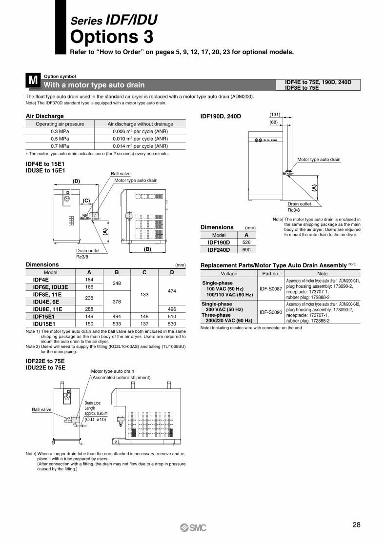
The float type auto drain used in the standard air dryer is replaced with a motor type auto drain (ADM200).
Operating air pressure
0.3 MPa
0.5 MPa
0.7 MPa
Air discharge without drainage
0.006 m3 per cycle (ANR)
0.010 m3 per cycle (ANR)
0.014 m3 per cycle (ANR)
∗ The motor type auto drain actuates once (for 2 seconds) every one minute.
IDF22E to 75EIDU22E to 75E
IDF4E to 15E1IDU3E to 15E1
(D)
(A)
(B)
(C)
Drain outletRc3/8
Motor type auto drain
Ball valve
With a motor type auto drainM IDF4E to 75E, 190D, 240DIDF3E to 75E
Ball valve
Motor type auto drain
Drain tube: Length approx. 0.95 m(O.D. ø10)
Note) When a longer drain tube than the one attached is necessary, remove and re-place it with a tube prepared by users. (After connection with a fitting, the drain may not flow due to a drop in pressure caused by the fitting.)
Note 1) The motor type auto drain and the ball valve are both enclosed in the same shipping package as the main body of the air dryer. Users are required to mount the auto drain to the air dryer.
Note 2) Users will need to supply the fitting (KQ2L10-03AS) and tubing (TU1065BU) for the drain piping.
Air Discharge
IDF4EIDF6E, IDU3EIDF8E, 11EIDU4E, 6EIDU8E, 11EIDF15E1IDU15E1
Model
154
166
238
288
149
150
A
348
378
494
533
B
133
146
137
C
474
496
510
530
D(mm)Dimensions
Note) Including electric wire with connector on the end
Single-phase 200 VAC (50 Hz)Three-phase 200/220 VAC (60 Hz)
Voltage Part no. Note
IDF-S0090
Assembly of motor type auto drain: ADM200-041, plug housing assembly: 173090-2, receptacle: 173707-1, rubber plug: 172888-2Assembly of motor type auto drain: ADM200-042, plug housing assembly: 173090-2, receptacle: 173707-1, rubber plug: 172888-2
Replacement Parts/Motor Type Auto Drain Assembly Note)
IDF190D, 240D
IDF190DIDF240D
Model
526
690
ADimensions (mm)
Note) The motor type auto drain is enclosed in the same shipping package as the main body of the air dryer. Users are required to mount the auto drain to the air dryer.
(Assembled before shipment)
(68)
Motor type auto drain
(A)
Drain outletRc3/8
(131)
Note) The IDF370D standard type is equipped with a motor type auto drain.
Series IDF/IDUOptions 3Refer to “How to Order” on pages 5, 9, 12, 17, 20, 23 for optional models.
Option symbol
IDF-S0087Single-phase 100 VAC (50 Hz) 100/110 VAC (60 Hz)
28

With a circuit breakerRThe air dryer is equipped with a circuit breaker, reducing the electrical wiring required during installation. (The IDF370D does not include the electrical leakage detection function.)
Except IDF1E, 2E, 3E
IDF4E to 15E1IDU3E to 15E1
IDF190D, 240D IDF370D
IDF22E to 75EIDU22E to 75E
A
D40
C
Grommet with membrane
EPower cable outlet (ø17)
Circuit breaker
B
IDF100F to 150F
IDF4E, 6E, 8E, 11EIDF15E1IDU3E, 4E, 6EIDU8EIDU11EIDU15E1
Model
32
43
32
42
43
230
258
230
258
97
102
97
100
102
34
82
34
37
75
82
15
—
15
—
EDCBA
60
Circuit breaker
C
E
B D
F Power cable outlet (ø17)(Electric wire diameter ø9 to 11) [opposite side]
A
(mm)Dimensions
ModelVoltage
100 Vtype
10 A
30 mA
—
IDF4E-10, IDF6E-10IDF8E-10, IDF11E-10, IDF15E1-10
IDU3E-10, IDU4E-10, IDU6E-10IDU8E-10, IDU11E-10, IDU15E1-10
200 Vtype
Breakercapacity
5 A
10 A
Sensitivitycurrent
IDF4E-20, IDF6E-20IDF8E-20, IDF11E-20
IDU3E-20, IDU4E-20IDU6E-20, IDU8E-20, IDU11E-20
IDF15E1-20, IDF22E-20, IDF37E-20IDU15E1-20IDF22E-30, IDF37E-30IDF55E-30IDU22E-30, IDU37E-30, IDU55E-30
15 A
30 A
50 A
IDF75E-30, IDU75E-30IDF100FIDF125FIDF150FIDF190DIDF240DIDF370D
Breaker Capacity and Sensitivity Current
IDF22E-20IDF37E-20IDF22E-30IDF37E-30IDF55E-30IDF75E-30IDU22E-30IDU37E-30IDU55E-30IDU75E-30
Model
125
148
133
151
146
148
166
A
59
39
81
73
74
122
55
73
B
60
60
C
40
60
60
D
25
50
50
70
E
46
36
46
36
F(mm)Dimensions
IDF190DIDF240D IDF370D
Model
95
156
ADimensions
No-fuse breaker
ø35
Power connection
(A)
(mm)
IDF100FIDF125F IDF150F
Model
535
537
B434
448
628
ADimensions (mm)
Circuit breaker with cover
(A)
B
A
Series IDF/IDUOptions 4Refer to “How to Order” on pages 5, 9, 12, 17, 20, 23 for optional models.
Option symbol
29

Power supply terminal block connectionSThe option allows the connection of a power cable to a terminal block.This option is supplied with the 200 V model as a standard accessory.
T
Besides terminals for the power supply, terminals for the operating signaland the error signal are also available. (No-voltage contact)Additionally, when using the remote operation, select the Made to Order (IDF8E to 75E--X256, IDU8E to 75E--X256) products.
IDF1E-10 to 15E1-10,IDU3E-10 to 15E1-10
BD
C
A
Terminal block Grommet with membraneSignal cable outlet (ø17)
Grommet with membranePower cable outlet (ø17)
B
A
Grommet with membranePower cable outlet (ø17)
Terminal block
(33)
30
(98)
94
Terminal block
Grommet with membranePower outlet (ø17)
IDF1E-10 to 3E-10
IDF4E-10 to 15E1-10IDU3E-10 to 15E1-10
IDF4E to 15E1IDU3E to 15E1
53
IDF4E, 6E, 8E, 11EIDF15E1IDU3E, 4E, 6EIDU8E, 11EIDU15E1
Model
32
43
32
42
43
230
258
230
230
258
A B
IDF4E, 6E, 8E, 11EIDF15E1IDU3E, 4E, 6EIDU8E, 11EIDU15E1
Model
32
43
32
42
43
230
258
230
230
258
A B67
77
67
77
77
C179
158
179
136
158
D
Note) Be sure to confirm the electric circuits with the drawings or Operating Manual before using the operating and error signals.
Contact capacity: Operating signal ··· 220 VAC, 6 AError signal ··· 250 VAC, 7 A
Minimum current value: 24 V, 5 mA (AC/DC) for operating and error signals
(mm)
(mm)
Dimensions
Dimensions
IDF22E to 75E, IDU22E to 75E
Terminal block
Signal cable outlet (Electric wire diameter ø17)Grommet with membrane
C
ABD
Power cable holder(Electric wire diameter ø9 to ø11)
Contact capacity: Operating signal ··· 220 VAC, 6 AError signal ··· 250 VAC, 7 A
Minimum current value: 20 V, 5 mA (AC/DC) for operating and error signals
IDF22E, 37EIDF55E, 75EIDU22E, 37EIDU55EIDU75E
Model
25
50
50
70
46
36
46
36
A B135
207
166
230
242
C
81
D(mm)Dimensions
T
With a timer controlled solenoid valve type auto drain (applicable to moderate pressure)
V
Drainage is discharged by controlling a solenoid valve with a timer.A strainer for solenoid valve protection and a stop valve are also included.(The external dimensions are the same as the standard product.)
Maximum operating pressure: 1.6 MPa (IDF100F to 150F: 1.0 MPa)
∗ The timer controlled solenoid valve actuates once (for 0.5 seconds) every 30 seconds.
IDU3E to 75E-23IDF100F to 150F
Replacement PartsModel Part no.
IDF-S0198
IDF-S0302
IDF-S0405
230 VAC
200 VAC
IDU3E to 37E-23IDU55E, 75E-23IDF100F to 150F
Note
Series IDF/IDUOptions 5Refer to “How to Order” on pages 5, 9, 12, 17, 20, 23 for optional models.
Option symbol Option symbol
IDF22E to 75E, IDU22E to 75E
With a terminal block for power supply, operating and error signals
With a terminal block for power supply, operating and error signals
Option symbol
IDF4E to 15E1, IDU3E to 15E1
Option symbol
30

Water-cooled typeOption symbol
It can be used in a high temperature environment without decreasing air flow capacity. It can also be used in an enclosed environment without increasing the ambient temperature. This option is supplied with the IDF370D as a standard accessory.
W IDF100F to 150F, 190D, 240D
IDF100F to 150F
IDF190D, 240D
Model
Condenser
Water flow regulator
Port size for water side
Shell and coil systemPlate system
Pressure type automatic water supply valve
R1R3/4R1/2
Note 1) Value with rated load when cooling water inlet temperature is 32°C.Note 2) Calculated at 1 RT = 3300 kcal/h
IDF125F
1.74/1.98
2.4
IDF100F
1.29/1.56
2
IDF150F
2.16/2.52
3
IDF190D
4.8/4.8
7.5
IDF240D
5.4/5.4
7.5
Model
IDF100F
IDF125F, 150F
A384
234
B
127
C
479
(mm)Dimensions
Model
IDF190D, 240DA
180
B250
C160
D48
E273
(mm)Dimensions
Cooling water outlet
Cooling water inlet
Condensation pressure gauge
Drain plug
Rc3/8
A
ED
C
B
Cooling towerperformance (RT) Note 2)
Cooling water flow rate (m3/h) Note 1) 50/60 Hz
Series IDF/IDUOptions 6Refer to “How to Order” on pages 5, 9, 12, 17, 20, 23 for optional models.
A
CB
31

Description Features Applicable air dryerIDF1E-10 to IDF15E1-10, IDF22E-20/30IDF37E-20/30, IDF55E-30, IDF75E-30IDU3E-10 to 15E1-10, IDU22E to 75E-30IDF100F to 150F, IDF190D to 370D-3
IDF4E to 15E1-10IDF22E-20/30, IDF37E-20/30IDF55E-30, IDF75E-30IDU3E to 15E1-10
IDF1E to 75EIDF190D to 240DIDU3E to 75E
IDF1E to 75E
IDU3E to 75E
IDF4E to 75EIDU3E to 75EIDF100F to 150F
Specifications
Max. ambient temperature40°C
(Relative humidity 85% or less)
—
Max. ambient temperature40°C
Max. operating pressure Note 4)
1.0 MPaMax. operating temperatureIDF: 60°C IDU: 80°C
Max. operating pressure Note 4)
1.0 MPaMax. operating temperature
60°CMax. operating pressure Note 4)
1.0 MPaMax. operating temperature
60°C
Stainless steel
Dimensions
Page34, 35
Page36
Page37
Page38, 39
Page39
Page40
Page41
Dust-protectingfilter set Note 3)
Bypass piping set
Foundation bolt set
Dedicated base forseparately installedpower transformer Note 2)
Separately installedpower transformer Note 1), 2)
IDF1E to 75EIDU3E to 75EIDF100F to 150F
Brass
IDF22E, 37E—
IDF6E to 15E1
IDF6E to 15E1
Piping adapter
Mounting base adapter
Conversion piping set
Conversion bypass piping set
For integrating the separately installed power transformer and the air dryer.
Easy bypass piping (connect this set to the air dryer), allowing substantial reduction in the installation time.
For converting the thread type of an IN/OUT fitting for air dryers.
For ensuring conversion to the former models’ (IDF22C and 37C) air piping.
[When bypass piping is already in place]For ensuring conversion to the former models’ (IDF6D to 15C) air piping.
[When there is no bypass piping]For ensuring conversion to the former models’ (IDF6D to 15C) air piping.
For fixing the air dryer to the foundations. Easy to secure by striking the axle.
Separately installed powertransformer is not attached.Order separately.
Specifications
Note 1) When using a power transformer for the IDF1E to 15E1 and IDU3E to 15E1, select the air dryer of 100 V.Note 2) When using a power transformer for the IDF190D and 240D, built-in transformer type is also available. (Refer to “How to Order” on page 17.)Note 3) This filter set is supplied with the IDF100F to 150F as a standard accessory.Note 4) Not applicable to the moderate pressure specification. Prepare a bypass, conversion or conversion bypass piping set suitable for the specification.
How to Order
IDF TR 500 2
Three-phase type IDF TR 51700
CapacitySymbol
500
1000
2000
Applicable air dryerIDF1E-10 to IDF8E-10IDU3E-10, IDU4E-10, IDU8E-10IDF11E-10, IDF15E1-10IDU6E-10, IDU11E-10, IDU15E1-10IDF22E-20, IDF37E-20
Capacity
500 VA
1 kVA
2 kVA
Power supply voltageSymbol
1
2
3
4
9
10
11
Inlet voltage110 VAC (50 Hz)110 to 120 VAC (60 Hz)200, 220, 230, 240 VAC (50 Hz)200 to 260 VAC (60 Hz)380, 400, 415 VAC (50 Hz)380 to 420 VAC (60 Hz)420, 440, 480 VAC (50 Hz)420 to 520 VAC (60 Hz)220 VAC (50 Hz)220 to 240 VAC (60 Hz)380, 400, 415 VAC (50 Hz)380 to 400, 400 to 415, 415 to 440 VAC (60 Hz)440, 460 VAC (50 Hz)440 to 460, 460 to 500 VAC (60 Hz)
Outlet voltage
100 VAC (50 Hz)100, 110 VAC
(60 Hz)
200 VAC (50 Hz)200, 220 VAC
(60 Hz)
Type
Single-phase
Single-phase
Note) Refer to pages 34 and 35 for dimensions.
CapacitySymbol Capacity
1.7 kVA
4 kVA
Applicable air dryerIDF22E-30, IDF37E-30IDU22E-30, IDU37E-30IDF55E-30, IDF75E-30IDU55E-30, IDU75E-30
1700
4000
7 kVA9 kVA
14 kVA18 kVA
IDF100FIDF125F, 150FIDF190D, 240DIDF370D
700090001400018000
Power supply voltageSymbol
5
6
7
8
Inlet voltage220 VAC (50 Hz)220 to 240 VAC (60 Hz)380, 400, 415 VAC (50 Hz)380 to 440 VAC (60 Hz)440, 460 VAC (50 Hz)440 to 500 VAC (60 Hz)220, 240, 380, 400, 415, 440 VAC (50/60 Hz)
Outlet voltage
200 VAC (50 Hz)200, 220 VAC
(60 Hz)
200 VAC (50/60 Hz)
Type
Three-phase
Note) Refer to page 35 for dimensions.
[Separately installed power transformer]Single-phase type
Series IDF/IDUOptional Accessories
Power supply and voltage for those other than the standard.
For preventing a decline in the performance of air dryers, even in a dusty atmosphere.
32

How to Order
IDF FL D190Applicable air dryer
Symbol190240
Applicable air dryerIDF190D IDF240D
IDU FL 210Applicable air dryer
Symbol210211212215216217218
Applicable air dryerIDU8EIDU11EIDU15E1IDU22EIDU37EIDU55EIDU75E
[Dust-protecting filter set]
IDF FL 201Applicable air dryerSymbol200 Note)
201 Note)
202203204205206207208213214
Applicable air dryerIDF1E, 2E
IDF3EIDF4E
IDF6E, IDU3EIDF8E, IDU4EIDF11E, IDU6E
IDF15E1IDF22EIDF37EIDF55EIDF75E
Note) This filter set is supplied with the IDF100F to 150F as a standard accessory.Refer to page 37 for dimensions.
IDF TBSize
Symbol403404405406409
Applicable air dryerIDF4E to 11E, IDU3E to 6E
IDF15E1IDF22EIDF37E
IDF55E, IDF75ENote) Not available for the IDF1E to 3E, IDU22E to 75E, IDF100F to 150F, IDF190D, 240D, 370D.
In the case of the option S, the part number will be different. Please consult with SMC separately.Refer to page 36 for dimensions.
403 IDU TBSize
Symbol407408
Applicable air dryerIDU8E, IDU11E
IDU15E1
407[Dedicated base for separately installed power transformer]
IDF BP BP[Bypass piping set (Rc, R thread)]
302Applicable air dryer
Applicable air dryerIDF1EIDF2EIDF3EIDF4E
IDF6E to 11EIDF15E1IDF22EIDF37EIDF55EIDF75E
Thread type
Rc
R
Symbol300301302303304316317318
325
IDU 305Applicable air dryer
Symbol305306307320322336337338
Applicable air dryerIDU3EIDU4EIDU6E
IDU8E, IDU11EIDU15E1IDU22EIDU37E
IDU55E, IDU75ENote) Refer to pages 38 and
39 for bypass piping set dimensions.
Note) Not applicable to the moderate pressure specification (maximum operating pressure 1.6 MPa). Prepare a bypass piping set suitable for the specification by users.
500IDF ABApplicable air dryer
[Foundation bolt set]
Symbol
500
501
Applicable air dryerIDF4E to 75E
IDU3E to 15E1IDF100F to 150F
Note) Refer to page 39 for dimensions.
[Piping adapter]
IDF AP 601Applicable air dryer
Thread type and port sizeMale thread A side
R1/2R3/4NPT1
R1NPT1 1/2
NPT2R3/8
NPT1/2NPT3/4
Rc1NPT1
Rc1 1/2Rc2
NPT3/8
Female thread B sideApplicable air dryer
IDF4E, IDU4EIDF6E to 11E, IDU6E to 11E
IDF22E, IDU22EIDF15E1, IDU15E1IDF37E, IDU37EIDF100F to 150F
IDF1E to 3E, IDU3E
Symbol
601603604605606607609
Note) Refer to page 39 for dimensions.
Series IDF/IDU
Applicable to the IDF22E and 37E.
[Mounting base adapter]
Part no.IDF-S0189IDF-S0147
Applicable air dryerIDF22EIDF37E
Note) Refer to page 40 for dimensions.
[Conversion piping set/Conversion bypass piping set]
Conversion piping setIDF-S0186IDF-S0203IDF-S0187IDF-S0188
Conversion bypass piping setIDF-S0183IDF-S0202IDF-S0184IDF-S0185
Part no.Applicable air dryer
IDF6EIDF8E
IDF11EIDF15E1
Note) Refer to pages 40 and 41 for dimensions.
Applicable to the IDF6E to 15E1.Select “conversion piping set” when bypass piping is already in place, and “conversion bypass piping set” when there is no bypass piping.
33

Part no. Applicable air dryer Capacity TypeInlet
voltageOutletvoltage
A B C D E F Weight
IDF-TR500-1 IDF1E-10 to 8E-10IDU3E-10, 4E-10, 8E-10
IDF-TR1000-1 IDF11E-10, 15E1-10IDU6E-10, 11E-10, 15E1-10
500 VA
1 kVA
Single-phaseSingle-
turn
110 VAC(50 Hz)110 to
120 VAC(60 Hz)
100 VAC(50 Hz)
100,110 VAC(60 Hz)
78 94 100 64 75 4.2 x 7(Long hole)
1.5 kg
104 122 134 75 114 4.2 x 9(Long hole)
4 kg
Part no.
200, 220230, 240 VAC
(50 Hz)200 to
260 VAC(60 Hz)
Applicable air dryer Capacity TypeInlet
voltageOutletvoltage
A B C D E F Weight
IDF-TR500-2 IDF1E-10 to 8E-10IDU3E-10, 4E-10, 8E-10
IDF-TR1000-2 IDF11E-10, 15E1-10IDU6E-10, 11E-10, 15E1-10
500 VA
1 kVA
Single-phaseSingle-
turn
100 VAC(50 Hz)
100,110 VAC(60 Hz)
118 140
163 70 112 142 6 kg
208 90 157 187 10 kg
Part no. Applicable air dryer Capacity TypeInlet
voltageOutletvoltage
A B C D E F Weight
IDF-TR500-3 IDF1E-10 to 8E-10IDU3E-10, 4E-10, 8E-10
IDF11E-10, 15E1-10IDU6E-10, 11E-10, 15E1-10
IDF1E-10 to 8E-10IDU3E-10, 4E-10, 8E-10
IDF11E-10, 15E1-10IDU6E-10, 11E-10, 15E1-10
500 VA
1 kVA
500 VA
1 kVA
Single-phaseSingle-
turn
380, 400,415 VAC (50 Hz)
380 to420 VAC (60 Hz)
420, 440,480 VAC (50 Hz)
420 to520 VAC (60 Hz)
100 VAC(50 Hz)
110 VAC(60 Hz)
230 207 190 210 160 9
15 kg
IDF-TR1000-3
IDF-TR1000-4
IDF-TR500-422 kg
A
B
D4 x F
C
E
Input cable 2 m
A
B
D4 x øF
E
Input cable 2 m
C
OUT PUT
IN PUT
VOLTAGESELECTOR
FUSE
OUT PUT IN PUT
E
C
F
B
D
A
Input cable 2 m
Output outlet
240V
200V
230V
220V
INPUT
OUTPUT label
Voltage selector
4 x 5.5 x 10 Long hole
Input fuse
5A
IDF-TR 1
IDF-TR 2
IDF-TR 3, 4
(mm)
(mm)
(mm)
Specifications/Dimensions
Specifications/Dimensions
Specifications/Dimensions
Specifications/Dimensions
[Separately installed power transformer]
Optional Accessories Series IDF/IDU
34

Part no. Applicable air dryer
IDF22E-30IDF37E-30IDU22E-30IDU37E-30
1.7 kVA
380, 400, 415 VAC (50 Hz)380 to 400, 400 to 415,415 to 440 VAC (60 Hz)
200 V(50 Hz)
200, 220 V(60 Hz)
18 kg
Three-phaseSingle-
turn
Capacity Type Inlet voltage Outlet voltage Weight
IDF-TR1700-6
440, 460 VAC (50 Hz)440 to 460,
460 to 500 VAC (60 Hz)IDF-TR1700-7
Part no. Applicable air dryer
IDF22E-20IDF37E-20
2 kVA
380, 400,415 VAC (50 Hz)
380 to 400,400 to 415,
415 to 440 VAC (60 Hz)
200 VAC(50 Hz)
200, 220 VAC(60 Hz)
20 kg
Single-phaseSingle-
turn
Capacity Type Inlet voltage Outlet voltage Weight
IDF-TR2000-10
440, 460 VAC (50 Hz)440 to 460,
460 to 500 VAC (60 Hz)IDF-TR2000-11
Part no. Applicable air dryerIDF22E-30IDF37E-30IDU22E-30IDU37E-30
1.7 kVA220 VAC (50 Hz)
220 to 240 VAC (60 Hz)200 V (50 Hz)
200, 220 V (60 Hz)9 kg
Three-phaseSingle-
turn
Capacity Type Inlet voltage Outlet voltage Weight
IDF-TR1700-5
IDF-TR1700-5
IDF-TR1700-6,7
Part no. Applicable air dryerIDF22E-20IDF37E-20
2 kVA220 VAC (50 Hz)
220 to 240 VAC (60 Hz)200 VAC (50 Hz)
200, 220 VAC (60 Hz)5 kg
Single-phaseSingle-turn
Capacity Type Inlet voltage Outlet voltage Weight
IDF-TR2000-9
IDF-TR2000-9
IDF-TR2000-10,11
IDF-TR4000-5,6,7
Part no. Applicable air dryer
IDF55E-30IDF75E-30IDU55E-30IDU75E-30
4 kVA
220 V (50 Hz)220 to 240 V (60 Hz)
380, 400, 415 V (50 Hz)380 to 400, 400 to 415,415 to 440 V (60 Hz)
440, 460 V (50 Hz)440 to 460,
460 to 500 V (60 Hz)
200 V (50 Hz)200, 220 V (60 Hz)
200 V (50 Hz)200, 220 V (60 Hz)
200 V (50 Hz)200, 220 V (60 Hz)
275
355
355
259
299
299
240
320
320
14 kg
35 kg
42 kg
Three-phaseSingle-
turn
Capacity Type Inlet voltage Outlet voltage Weight
IDF-TR4000-5
IDF-TR4000-6
IDF-TR4000-7
A B C
Terminal block
140
110 15
158
190
175 7.5
ø26
Cable hole
150
130
4 x ø7
250
220 15
295
250
220
4 x ø10
243Terminal block
290
270 10
Cable hole
ø39
220
290
10
295
270
243
259
ø39Cable hole
4 x ø10 250
15220
Terminal block
183
200
205 4 x ø8
ø30
Terminal block
160 15
190
Terminal block
220
C 45Bø30
A 4 x ø11
Specifications
Specifications
Specifications
Specifications
Specifications/Dimensions
[Separately installed power transformer]
(mm)
(mm)
(mm)
(mm)
(mm)
Part no. Applicable air dryerIDF100F
IDF125F, 150FIDF190D, 240D
IDF370D
7 kVA9 kVA14 kVA 18 kVA
220, 240,380, 400,
415,440 V (50/60 Hz)
200V(50/60 Hz)
Capacity Type360400400400
A540650650650
B400450450450
C260300300300
D300350350350
E11131313
F30404040
G 94 kg109 kg152 kg179 kg
WeightInlet voltage Outlet voltageIDF-TR7000-8IDF-TR9000-8IDF-TR14000-8IDF-TR18000-8
Specifications/Dimensions
Three-phase
Double-turn
E
D4 x øF A
C
øG
B
(mm)
Specifications/Dimensions
IDF-TR 8
Series IDF/IDU
35

IDF4E to 75EIDU3E to 15E1
D
C
15
E
F 65 (125: For IDF55E, 75E)
75
G
A
B
4 x ø13
Separately installedpower transformer
Dedicated base for separatelyinstalled power transformer
[Dedicated base for separatelyinstalled power transformer]
Applicable air dryerPart no. Applicable transformer Reference weight (including air dryer and transformer) (kg)
Unit weight(kg)A
IDF4E-10
IDF6E-10IDU3E-10
IDF8E-10IDU4E-10
IDF11E-10IDU6E-10
IDF-TR500-1IDF-TR500-2IDF-TR500-3IDF-TR500-4IDF-TR500-1IDF-TR500-2IDF-TR500-3IDF-TR500-4IDF-TR500-1IDF-TR500-2IDF-TR500-3IDF-TR500-4
IDF-TR1000-1IDF-TR1000-2IDF-TR1000-3IDF-TR1000-4
573
643
B C
345
370
D
315
340
E
45
F
385
G
515 6
29.534 43 50
30.535 44 51
34.539 48 55 38 44 49 56 57 63 68 75 75 84 71 86 84 93 80 95
129 150 157 145 166 173
IDF-TB403
171217
284
171217
284
171217
284
199217
284
215233
300
300352243343300352243343397
437
397
437
(mm)IDF-TB/Dimensions
IDF-TR1000-1IDF-TR1000-2IDF-TR1000-3IDF-TR1000-4IDF-TR1700-5
IDF-TR1700-6, 7IDF-TR2000-9
IDF-TR2000-10, 11IDF-TR1700-5
IDF-TR1700-6, 7IDF-TR2000-9
IDF-TR2000-10, 11IDF-TR4000-5IDF-TR4000-6IDF-TR4000-7IDF-TR4000-5IDF-TR4000-6IDF-TR4000-7
IDF15E1-10
IDF22E-30
IDF22E-20
IDF37E-30
IDF37E-20
IDF55E-30
IDF75E-30
IDF-TB404
IDF-TB405
IDF-TB406
IDF-TB409
653 450 420 66 427 557
773
630 600
70
675
805
943
1043
730 750 60 925
7
12
13
15
710 680
IDF-TR500-1IDF-TR500-2IDF-TR500-3IDF-TR500-4
IDF-TR1000-1IDF-TR1000-2IDF-TR1000-3IDF-TR1000-4IDF-TR1000-1IDF-TR1000-2IDF-TR1000-3IDF-TR1000-4
Applicable air dryerPart no. Applicable transformer Reference weight (including air dryer and transformer) (kg)A
IDU8E-10
IDU11E-10
IDU15E1-10
IDU-TB407
IDU-TB408
B C D E F G
934
370 340 45 475 605
984
1035 540 510 31 487 617
6
10
171217
284
199217
284
215233
300
51.556 65 72 57 63 68 75 85 91 96
103
(mm)
Unit weight(kg)
IDU-TB/Dimensions
Dimensions
Optional Accessories Series IDF/IDU
36

(IDF-FL200, 201) (IDF-FL202 to 214) (IDU-FL210 to 218)
(A)(20)
(B)
(10)
(20)
Part no. Applicable air dryer Weight (g)A B
IDU8E
IDU11E
IDU15E1
IDU22E
IDU37E
IDU55E
IDU75E
375375375360440440420555550580720735610735
265265265320370375315415365540400515560515
75 75 75 90120120100170140230175265190265
IDU-FL210
IDU-FL211
IDU-FL212
IDU-FL215
IDU-FL216
IDU-FL217
IDU-FL218
(mm)Dimensions
[Dust-protecting filter set]
Part no. Applicable air dryer Weight (g)A BIDF1E, 2E
IDF3EIDF4E
IDF6E, IDU3EIDF8E, IDU4EIDF11E, IDU6E
IDF15E1IDF22EIDF37EIDF55EIDF75E
220
310375340375440420550720610
150200
195
265
370315365400560
20 30 45 55 70 75120100140175190
(mm)
IDF-FL200IDF-FL201IDF-FL202IDF-FL203IDF-FL204IDF-FL205IDF-FL206IDF-FL207IDF-FL208IDF-FL213IDF-FL214
Dimensions
∗ A filter set for the IDF-FL200 to 214 consists of 1 filter.
∗ A filter set for the IDU-FL210 to 212, 215 to 218 consists of 2 filters.
Part no. Applicable air dryer A B
IDF190D
IDF240D
250750440600
480480670670
IDF-FL190D
IDF-FL240D
(mm)Dimensions
∗ A filter set for the IDF-FL190D to 240D consists of 4 filters.
Dimensions
Series IDF/IDU
37

Part no.
IDF-BP303
IDF-BP304
IDF-BP316IDU-BP305IDU-BP306IDU-BP307
Applicableair dryer
IDF4E
IDF6E
IDF8E
IDF11E
IDF15E1
IDU3E
IDU4E
IDU6E
Port sizeRc A B C
31
41
31
175
187
210
202
175
187
531
555
627
710
506
603
627
D
595
617
647
774
572
625
647
E
110
129
136
100
110
129
Weight(kg)
2.3
3.3
5.3
1.6
2.3
3.3
1/2
3/4
1
3/8
1/2
3/4
IDF
IDU
Part no.
IDF-BP300IDF-BP301IDF-BP302
Applicableair dryer
IDF1E
IDF2E
IDF3E
Port sizeRc A B C
56 114
549
628
642
D
440
443
445
E
21
Weight(kg)
1.5
1.6
IDF1E to 3EIDF4E to 15E1IDU3E to 6E
3/8
(C)
(B) (D)
(E)
(A)
Compressed air outletCompressed air inletPort size
(B)(D)
(A)
(C)
Compressed air outletCompressed air inlet
Port size(E)
(mm)
(mm)
Dimensions
Dimensions
[Bypass piping set]
IDF22E, 37EIDU22E to 75E
IDF55E, 75E
(D) (B) (A)
(C)
Compressed air outletPort size
Compressed air inletPort size
Part no.
IDF-BP325
Applicableair dryerIDF55EIDF75E
A
11911291
Port sizeRc
2 12.3
Weight(kg)
Part no.
IDF-BP317IDF-BP318IDU-BP336IDU-BP337
IDU-BP338
Applicableair dryerIDF22EIDF37EIDU22EIDU37EIDU55EIDU75E
A
134
93 64
53
Port sizeRc1
1 1/21
1 1/2
2
B
405
445550
530
C D
198
46 70
110
Weight(kg)
928 9801465163517831918
4.4 7.7 4.5 8.0
12.3
(mm)Dimensions
Dimensions
(519)
(110) (250)
(128)(455)(A
)
Compressed air inlet
Port sizeCompressed air outlet
Port size
(mm)
Dimensions
IDF
IDU
Optional Accessories Series IDF/IDU
38

IDU8E to 15E1
(D)
(E)
(F)(B) (A)
(C)
Compressedair inletPort size
Compressedair outletPort size
Part no.
IDU-BP320
IDU-BP322
Applicableair dryerIDU8EIDU11EIDU15E1
BPort sizeRc
3/4
1
A
31
79210
687
745
647
791
129
136
3.6
5.3
C D E Weight(kg)
(mm)
Part no. Applicable air dryer Material
IDF-AP601
IDF-AP603
IDF-AP604IDF-AP605IDF-AP606
IDF-AP607
IDF-AP609
Thread type and port sizeMale thread A side Female thread B side
R1/2
R3/4
NPT1R1
NPT1 1/2
NPT2
R3/8
NPT1/2
NPT3/4
Rc1NPT1
Rc1 1/2
Rc2
NPT3/8
IDF4EIDU4E
IDF6E to 11EIDU6E to 11EIDF22E, IDU22EIDF15E1, IDU15E1IDF37E, IDU37EIDF55E, 75E, IDU55E, 75EIDF100 to 150F
IDF1E to 3EIDU3E
C
38
43
50
55
65
30
D E
Brass 2
Numberof 1 set
(mm)
23
23
27
31
35
15
26
32
46
54
70
22
E (Width across flats)
D
C
Male threadA side
Female thread B side
Dimensions
Dimensions
[Bypass piping set]
[Piping adapter]
[Foundation bolt set]
Part no.
IDF-AB500
IDF-AB501
Applicable air dryer
IDF4E to 75EIDU3E to 15E1IDU22E to 75EIDF100 to 150F
Nominalthread size
Material
M10Stainless
steel 450
70
Numberof 1 set A
Dimensions (mm)
Dimensions
Series IDF/IDU
A
Mounting hole dia.: ø10.5
39

4 x ø13
(A)(405)(134)
C(101)
B
(290)
(93)
FE G
4 x ø13
4 x ø13
4 x ø13
(D)
(109)
240
270
(410) (71)
275 85
(587)
(405)(134) (105)
270
300
380 106
(748)
(61)
(331)
240
270
(B) (C)
(A)
(722
)
(602
)
300 (90)
(617)
Compressedair inlet
Compressedair outlet
Compressed air inletCompressed air outlet
Compressed air inletCompressed air outlet
Compressed air outletPort size
Compressed air inletPort size
Part no.
IDF-S0189IDF-S0147
Applicable air dryer
IDF22E
IDF37E
Port size R A B C
775
855
17
30
600
680
D
760
810
E
323
348
F
362
376
G
25
14
Reference weight(including air dryer)
(kg)
57
66
Single unitweight
(kg)
3
4
IDF22E, 37E
1
1 1/2
(mm)Dimensions
Part no.
IDF-S0203IDF-S0187
Applicable air dryer
IDF8E
IDF11E
Port size Rc A B C609
669
410
405
75
89
Weight (kg)
3.8
4.0
3/4
3/4
(mm)Dimensions
Part no.
IDF-S0186Applicable air dryer
IDF6E
Port size Rc Weight (kg)
3.51/2
Port SizePart no.
IDF-S0188Applicable air dryer
IDF15E1
Port size Rc Weight (kg)
6.71
Port Size
[Mounting baseadapter]
IDF6E
IDF8E, 11E
[Conversion piping set]IDF15E1[Conversion piping set]
Dimensions
Optional Accessories Series IDF/IDU
40

4 x ø13
(F) (G)(B)
EC D
(A)
(J)H I
Compressed air inletPort size
Compressed air outletPort size
Part no.
IDF-S0183IDF-S0202IDF-S0184IDF-S0185
Applicableair dryer
IDF6E
IDF8E
IDF11E
IDF15E1
Port sizeRc A B C
725
749
815
897
109
111
138
135
240
240
240
270
D
15
15
15
15
E
270
270
270
300
F
410
410
405
405
G
71
75
89
105
H
275
300
300
380
I
85
90
90
106
J
616
646
653
775
Weight(kg)
5.6
6.1
6.3
10.2
IDF6E to 15E1
1/2
3/4
3/4
1
(mm)Dimensions
[Conversion bypass piping set]
Dimensions
Series IDF/IDU
41
• Avoid locations where the air dryer will be in direct contact with wind and rain. (Avoid locations where relative humidity is 85% or more.)
• Avoid exposure to direct sunlight.• Avoid locations that contain much dust, corrosive gases, or
flammable gases. Failure due to corrosion is not covered under warranty. However, when the risk of corrosion is high, select the option C (anti-corrosive treatment for copper tube).
• Avoid locations of poor ventilation and high temperature.• Avoid locations where the air dryer is too close to a wall etc.
Leave a sufficient space between the air dryer and the wall according to the “Maintenance Space” in the Operation Manual.
• Avoid locations where the air dryer could draw in high temperature air discharged from an air compressor or other dryer.
• Avoid locations subjected to vibration.• Avoid possible locations where the drain can freeze.• Avoid locations with an ambient temperature 40°C or higher
(IDF100F to 150F: 45°C or higher).• Avoid installation on machines for transporting, such as vehicles,
ships, etc.
Installation
Caution
• A polyurethane tube is attached as a drain tube for the IDF1E to 150F, IDU3E to 75E. Use this tube to discharge drainage to a drain tank etc.
• Do not use the drain tube in an upward direction. Do not bend or crush the drain tube. (Otherwise, the operation of an auto drain will stop and drainage will discharge through the air outlet.) If it is unavoidable that the tube goes upward, make sure it only goes as far as the position of the auto drain.
Drain Tube
Caution
Confirm that the exhaust air does not flow into the neighboring equipment.
<100 VAC>• Insert the power supply plug to an exclusive 100 VAC power
outlet.• Install a circuit breaker Note 1) suitable to each model for the power
supply.• Maintain voltage fluctuation within ±10% of the rated voltage.• Be sure to ground the power supply prior to use.• Multiple-branch wiring is dangerous since it causes overheating.• Do not extend the power cable by using a table tap etc.
A voltage drop may cause the air dryer to stop operating.Note 1) Select a circuit breaker with a sensitivity current 30 mA
and a rated current 10 A.<200 VAC>• Connect the power supply to the terminal block.• Install a circuit breaker Note 2) suitable to each model for the power
supply.• Maintain voltage fluctuation within ±10% of the rated voltage.Note 2) Select a circuit breaker with a sensitivity current 30 mA.
As regards rated current, refer to “Applicable circuit breaker capacity” on pages 6, 10, 13, 14, 18, 21 and 24.
Power Supply
Caution
When using with other voltages than specified for a standard product, use a separately installed power transformer. (page 32)
Series IDF/IDUSpecific Product Precautions 1Be sure to read this before handling. Refer to the back cover for Safety Instructions. For Air Preparation Equipment Precautions, refer to “Handling Precautions for SMC Products” and the Operation Manual on SMC website, http://www.smcworld.com
42

IDF55E, 75E Compressed air inletCompressed air outlet
Valve open
Valve closed
• When tightening the inlet/outlet air piping, firmly hold the hexagonal parts of the port on the air dryer side or piping with a wrench or adjustable angle wrench.
• Variations in operating conditions may cause condensation to form on the surface of the outlet piping. Apply thermal insulation around the piping to prevent condensation from forming.
• Confirm that vibrations resulting from the compressor are not transmitted through the air piping to the air dryer.
• Do not allow the weight of the piping to lie directly on the air dryer.
• Be careful to avoid an error in connecting the air piping at the compressed air inlet (IN) and outlet (OUT).
• Install bypass piping since it is needed for maintenance.
Air Piping
Caution
IDF4E to 15E1IDU3E to 15E1
IDF22E, 37EIDU22E to 75E
IDF1E to 3ECompressed air outletCompressed air inlet
Valve closed
Valve open
Compressed air outletCompressed air inlet
Valve closed
Valve open
Compressed air inlet
Valve open
Compressed air outlet
Valve closed
When the air dryer is operated in the following cases, the protection circuit will activate, the lamp will turn off and the air dryer will come to stop.• The compressed air temperature is too high.• The compressed air flow rate is too high.• The ambient temperature is too high. (40°C or higher (IDF100F
to 150F: 45°C or higher))• The fluctuation of the power supply is beyond the rated voltage
±10%.• The air dryer is drawing in high temperature air exhausted from
an air compressor or other dryer.• The ventilation port is obstructed by a wall or clogged with dust.
Protection Circuit
Caution
Series IDF/IDUSpecific Product Precautions 2
Use the bypass piping set on pages 38 and 39.
Be sure to read this before handling. Refer to the back cover for Safety Instructions. For Air Preparation Equipment Precautions, refer to “Handling Precautions for SMC Products” and the Operation Manual on SMC website, http://www.smcworld.com
43

45° or more45° or more
Lifting position
The auto drain may not function properly, depending on the quality of the compressed air. Check the operation once a day.
Auto Drain
Caution
Remove dust from the ventilation area once a month using a vacuum cleaner or an air blow nozzle.
Cleaning of Ventilation Area
Caution
Allow at least three minutes before restarting the air dryer. Otherwise, the protection circuit will activate, the lamp will turn off and the air dryer will not start up.
Time Delay for Restarting
Caution
Do not modify the standard product using any of the optional specifications once the product has been supplied to a customer. Check the specifications carefully before selecting an air dryer.
Modifying the Standard Specifications
Caution
Be sure to follow the below instructions for transporting the product.• The product is filled with refrigerant. Transport it (by land, sea or
air) in accordance with laws and regulations specified.• When carrying the product, be careful not to let it drop or fall over.
Lift it by using a fork lift or rope and lifting hook. The lifting angle should be 45° or more.
Note) The lifting hooks are installed on the IDF100F to 150F.• Do not lift the product by holding the panel, fittings or piping.• Never lay the product down for transportation. This may lead to
damage to the product.
Transportation and Installation
Warning
Since the auto drain of the IDF2E to 75E, IDU3E to 75E is designed in such a way that the valve remains open unless the air pressure rises to 0.1 MPa or higher, air will blow out from the drain outlet at the time of air compressor start up until the pressure increases. Therefore, if an air compressor has a small air delivery, the pressure may not be sufficient.
Compressor Air Delivery
CautionUse an air compressor with an air delivery of 100 L/min or more for a model other than the IDF1E.
• The product is heavy and has potential dangers in transportation. Be sure to follow the above instructions.
• Be sure to use a fork lift or lifting hook for transporting the product.
Facility Water Supply (Water-cooled type)
Warning1. Be certain to supply the facility water.
1. Prohibition of water-cut operation, very little flow rate of water operation.Do not operate under the condition that there is no facility water or where there is very little flow rate of water is flowing.In this kind of operation, facility water temperature may become extremely higher. It is dangerous enough the material of hose may soften and burst when the piping supplying the facility water is connected with hose.
2. Actions to be taken when an emergency stop occurs due to high temperature.In case a stop occurs due to extremely high temperature resulting from a decrease in the facility water flow rate, do not immediately flow facility water. It is dangerous enough the material of hose may soften and burst when the piping supplying the facility water is connected with hose.First, naturally let it cool down by removing the cause of the flow rate reduction. Secondly, confirm that there is no leakage again.
Caution1. Facility water quality
1. Use the facility water within the specified range as shown below. When using with other fluids than facility water, please consult with SMC.
2. When it is likely that foreign matter may enter the fluid, install a filter (20 mesh or equivalent).
∗ In the case of [MΩ·cm], it will be 0.00125 to 0.01.
<Facility Water Quality Standard>
Standarditem
Referenceitem
Item pH (at 25°C )Electrical conductivity (25°C )Chloride ion (Cl–)Sulfuric acid ion (SO4
2–)Acid consumption amount (at pH4.8)Total hardnessCalcium hardness (CaCO3)Ionic state silica (SiO2)Iron (Fe)Copper (Cu)Sulfide ion (S2
–)Ammonium ion (NH4
+)Residual chlorine (Cl)Free carbon (CO2)
Unit—
[µS/cm][mg/L][mg/L][mg/L][mg/L][mg/L][mg/L][mg/L][mg/L][mg/L][mg/L][mg/L][mg/L]
Standard value6.5 to 8.2
100∗ to 800∗200 or less200 or less100 or less200 or less150 or less50 or less1.0 or less0.3 or less
Should not be detected.1.0 or less0.3 or less4.0 or less
Series IDF/IDUSpecific Product Precautions 3
The Japan Refrigeration and Air Conditioning Industry Association JRA GL-02-1994 “Cooling water system – Circulation type – Circulating water”
Be sure to read this before handling. Refer to the back cover for Safety Instructions. For Air Preparation Equipment Precautions, refer to “Handling Precautions for SMC Products” and the Operation Manual on SMC website, http://www.smcworld.com
44

Revision history
∗ Added Refrigerated Air Dryers, IDF15E/22E/37E, IDU8E/11E/15E.∗ Deleted Option H: Moderate Pressure
Specification (Auto drain bowl: Metal bowl).∗ Added Compressor Intake Condition to Air
Flow Capacity in the standard specifications.∗ Number of pages from 20 to 24 JZ
∗ Added Refrigerated Air Dryers, IDF55E/75E.∗ Added Piping Adapter to Optional Accessories.
Edition B
Edition C
Edition D
Edition E
Edition F
Edition GEdition H
Edition I
∗ Number of pages from 24 to 32 KV∗ Added Refrigerated Air Dryers, IDF120D to 240D, IDF370B.∗ Added Refrigerated Air Dryers, IDU22E/37E,
IDU55C/75C.∗ Number of pages from 32 to 44 LS∗ Added Refrigerated Air Dryers, IDU55E/75E.∗ Deleted Refrigerated Air Dryers, IDU55C/75C.∗ Number of pages from 44 to 52 MR
∗ Changed to Quick Reference Guide to Air Preparation Equipment∗ Number of pages from 52 to 48 OT∗ Not available∗ Updated pages 21 to 67 of the
Best Pneumatics No. 5 (Ver. 5). RZ∗ Power consumption and operating current for the
IDU37E-23 and IDU55E-23 are changed. SZ
CautionSMC products are not intended for use as instruments for legal metrology.Measurement instruments that SMC manufactures or sells have not been qualified by type approval tests relevant to the metrology (measurement) laws of each country. Therefore, SMC products cannot be used for business or certification ordained by the metrology (measurement) laws of each country.
Compliance Requirements
∗1) ISO 4414: Pneumatic fluid power – General rules relating to systems. ISO 4413: Hydraulic fluid power – General rules relating to systems. IEC 60204-1: Safety of machinery – Electrical equipment of machines. (Part 1: General requirements) ISO 10218-1: Manipulating industrial robots – Safety. etc.
Caution indicates a hazard with a low level of risk which, if not avoided, could result in minor or moderate injury.Caution:Warning indicates a hazard with a medium level of risk which, if not avoided, could result in death or serious injury.Warning:
Danger : Danger indicates a hazard with a high level of risk which, if not avoided, will result in death or serious injury.
Warning Caution1. The compatibility of the product is the responsibility of the
person who designs the equipment or decides its specifications.Since the product specified here is used under various operating conditions, its compatibility with specific equipment must be decided by the person who designs the equipment or decides its specifications based on necessary analysis and test results. The expected performance and safety assurance of the equipment will be the responsibility of the person who has determined its compatibility with the product. This person should also continuously review all specifications of the product referring to its latest catalog information, with a view to giving due consideration to any possibility of equipment failure when configuring the equipment.
2. Only personnel with appropriate training should operate machinery and equipment.The product specified here may become unsafe if handled incorrectly. The assembly, operation and maintenance of machines or equipment including our products must be performed by an operator who is appropriately trained and experienced.
3. Do not service or attempt to remove product and machinery/equipment until safety is confirmed.1. The inspection and maintenance of machinery/equipment should only be
performed after measures to prevent falling or runaway of the driven objects have been confirmed.
2. When the product is to be removed, confirm that the safety measures as mentioned above are implemented and the power from any appropriate source is cut, and read and understand the specific product precautions of all relevant products carefully.
3. Before machinery/equipment is restarted, take measures to prevent unexpected operation and malfunction.
4. Contact SMC beforehand and take special consideration of safety measures if the product is to be used in any of the following conditions. 1. Conditions and environments outside of the given specifications, or use
outdoors or in a place exposed to direct sunlight.2. Installation on equipment in conjunction with atomic energy, railways, air
navigation, space, shipping, vehicles, military, medical treatment, combustion and recreation, or equipment in contact with food and beverages, emergency stop circuits, clutch and brake circuits in press applications, safety equipment or other applications unsuitable for the standard specifications described in the product catalog.
3. An application which could have negative effects on people, property, or animals requiring special safety analysis.
4. Use in an interlock circuit, which requires the provision of double interlock for possible failure by using a mechanical protective function, and periodical checks to confirm proper operation.
1. The product is provided for use in manufacturing industries.The product herein described is basically provided for peaceful use in manufacturing industries. If considering using the product in other industries, consult SMC beforehand and exchange specifications or a contract if necessary. If anything is unclear, contact your nearest sales branch.
Limited warranty and Disclaimer/Compliance RequirementsThe product used is subject to the following “Limited warranty and Disclaimer” and “Compliance Requirements”.Read and accept them before using the product.
Limited warranty and Disclaimer1. The warranty period of the product is 1 year in service or 1.5 years after
the product is delivered, whichever is first.∗2)
Also, the product may have specified durability, running distance or replacement parts. Please consult your nearest sales branch.
2. For any failure or damage reported within the warranty period which is clearly our responsibility, a replacement product or necessary parts will be provided. This limited warranty applies only to our product independently, and not to any other damage incurred due to the failure of the product.
3. Prior to using SMC products, please read and understand the warranty terms and disclaimers noted in the specified catalog for the particular products.
∗2) Vacuum pads are excluded from this 1 year warranty.A vacuum pad is a consumable part, so it is warranted for a year after it is delivered. Also, even within the warranty period, the wear of a product due to the use of the vacuum pad or failure due to the deterioration of rubber material are not covered by the limited warranty.
1. The use of SMC products with production equipment for the manufacture of weapons of mass destruction (WMD) or any other weapon is strictly prohibited.
2. The exports of SMC products or technology from one country to another are governed by the relevant security laws and regulations of the countries involved in the transaction. Prior to the shipment of a SMC product to another country, assure that all local rules governing that export are known and followed.
Safety Instructions Be sure to read “Handling Precautions for SMC Products” (M-E03-3) before using.
These safety instructions are intended to prevent hazardous situations and/or equipment damage. These instructions indicate the level of potential hazard with the labels of “Caution,” “Warning” or “Danger.” They are all important notes for safety and must be followed in addition to International Standards (ISO/IEC)∗1), and other safety regulations.
Safety Instructions