Embed Size (px)
Citation preview
This article was downloaded by: [Ryerson University]On: 20 March 2013, At: 15:34Publisher: Taylor & FrancisInforma Ltd Registered in England and Wales Registered Number: 1072954 Registeredoffice: Mortimer House, 37-41 Mortimer Street, London W1T 3JH, UK
Journal of Modern OpticsPublication details, including instructions for authors andsubscription information:http://www.tandfonline.com/loi/tmop20
Reflection of light in the vicinity ofthe Brewster angle from a multilayersystem of ultrathin inhomogeneousdielectric filmsPeep Adamsona Institute of Physics, University of Tartu, Riia 142, Tartu 51014,EstoniaVersion of record first published: 19 Aug 2006.
To cite this article: Peep Adamson (2005): Reflection of light in the vicinity of the Brewster anglefrom a multilayer system of ultrathin inhomogeneous dielectric films, Journal of Modern Optics,52:10, 1457-1469
To link to this article: http://dx.doi.org/10.1080/09500340500052853
PLEASE SCROLL DOWN FOR ARTICLE
Full terms and conditions of use: http://www.tandfonline.com/page/terms-and-conditions
This article may be used for research, teaching, and private study purposes. Anysubstantial or systematic reproduction, redistribution, reselling, loan, sub-licensing,systematic supply, or distribution in any form to anyone is expressly forbidden.
The publisher does not give any warranty express or implied or make any representationthat the contents will be complete or accurate or up to date. The accuracy of anyinstructions, formulae, and drug doses should be independently verified with primarysources. The publisher shall not be liable for any loss, actions, claims, proceedings,demand, or costs or damages whatsoever or howsoever caused arising directly orindirectly in connection with or arising out of the use of this material.

Reflection of light in the vicinity of the Brewster angle
from a multilayer system of ultrathin inhomogeneous
dielectric films
PEEP ADAMSON*
Institute of Physics, University of Tartu,Riia 142, Tartu 51014, Estonia
(Received 18 October 2004; in final form 23 December 2004 )
An analysis of the influence of nanoscopically stratified dielectric overlayer on thereflection parameters of linearly polarized light from transparent substrates iscarried out. The second-order formulas for characteristic Brewster angles arederived and their accuracy is estimated by using exact numerical methods for thesolution of the inhomogeneous reflection problem. The possibilities are discussedfor determining the parameters of nanometre-scale dielectric layers by means ofcharacteristic reflection angles. A novel scanning angle differential reflectancemethod in the vicinity of the classical Brewster angle, whose sensitivity is inprinciple the same as that of ellipsometry, is developed.
1. Introduction
At present considerable attention has been focused on reflection methods used fordetermining the parameters of ultrathin films (see, e.g. [1, 2], and references therein).This is because the classical optical methods for simultaneous determination of theoptical constants and thickness of ultrathin films suffer many disadvantages [3, 4].Optical methods also offer the greatest promise for probing the near-surface regionand for studying thin-film processing in modern materials technology [5, 6].
For ultrathin dielectric films upon transparent substrates the crucial question isthe sensitivity of the measuring technique. Because of this, ellipsometric methods [7]have found extensive practical use. The reason is that for ultrathin films theellipsometric parameters are proportional to d=�, where d is the thickness of thefilm and � is the optical wavelength. At the same time, in the case of photometry,in which the reflected intensity is measured, it has been revealed that, generally, thecontribution of an ultrathin dielectric layer to the reflectance of a fully transparentsystem is very low [8, 9]. This circumstance arose from the fact that the contributionof an ultrathin dielectric layer upon a transparent substrate to the reflectanceis proportional to ðd=�Þ2 [10–12]. Therefore, for dielectric materials the sensitivityof ellipsometry, as a rule, exceeds the sensitivity of photometry by several ordersof magnitude.
Photometry, in comparison with ellipsometry, is a significantly more straight-forward technique and in view of this fact, the enhancement of the sensitivity
*Email: [email protected]
Journal of Modern OpticsVol. 52, No. 10, 10 July 2005, 1457–1469
Journal of Modern OpticsISSN 0950–0340 print/ISSN 1362–3044 online # 2005 Taylor & Francis Group Ltd
http://www.tandf.co.uk/journalsDOI: 10.1080/09500340500052853
Dow
nloa
ded
by [
Rye
rson
Uni
vers
ity]
at 1
5:34
20
Mar
ch 2
013

of photometric measurements is of particular interest. One way to increase thesensitivity is to use the measurements for p-polarized light in the neighbourhood ofthe classical Brewster angle ’B ¼ arctan ðns=naÞ (ns and na are the refractive indices ofthe transparent semi-infinite substrate and incident medium, respectively), where onecan obtain the necessary enhancement of the relative change of reflectance [13].Because of this, the reflectance methods at the Brewster angle [14–16] and scanningreflectometry around the Brewster angle [17–19] are already in general use. Further-more, it is pertinent to note that in fact the ‘Brewster approach’ has long been usedin thin-film optics (e.g. the familiar method developed by Abeles for determiningthe refractive index of dielectric films [20, 21]).
In addition to the classical Brewster angle for ideal (geometrical) interfaces, othercharacteristic Brewster angles that are experimentally measured can be introducedfor realistic physical surfaces, where an intermediate layer always exists, e.g. theprincipal angle of incidence, ’G, at which the phase difference between s- andp-polarization in the reflected ray is equal to 90� or the polarizing angle ’P, where therelation of the reflectance of p-polarized light to the reflectance of s-polarized light isa maximum. Note that at the Brewster angle ’B the reflected ray is normal to therefracted ray, and in practice ’B 6¼ ’G 6¼ ’P (it is only for geometrical interfaces that’B ¼ ’G ¼ ’P).
From a theoretical standpoint, ultrathin layers have an essential advantage.Namely, their thickness is much less than an optical wavelength, a property thatenables the reflection problem to be addressed analytically within the framework ofa long-wavelength approximation, i.e. by using perturbation theory. This circum-stance is of critical importance, due to the complexity of the exact analytical solutionof the reflection problem for a multilayer thin-film system. Furthermore, the relativelysimple analytical relationships are particularly attractive for tackling an inverseproblem, i.e. to determine the parameters of the layered nanoscopic structures [22].
The aim of this paper is to study the reflection of linearly polarized light inthe long-wavelength limit for an N-layer system of non-uniform nanometre-sizeisotropic dielectric films upon a transparent homogeneous isotropic substrate, andto show how one can use the reflection measurements in the vicinity of the classicalBrewster angle to determine the parameters of layered ultrathin structures.
The paper is organized as follows. In section 2 a closer examination of thecharacteristic Brewster angles for an N-layer system of ultrathin inhomogeneousfilms is carried out. A straightforward method for optical diagnostics of ultrathinlayers by combining characteristic angles and ellipsometry is also discussed. Next,section 3 is concerned with the novel interesting possibility of determining the opticalparameters of nanometre-size dielectric layers upon transparent substrates bydifferential reflectance measurements in the vicinity of the Brewster angle.
2. Characteristic Brewster angles
We consider the following characteristic reflection angles. First, the principal angleof incidence ’G, at which Re ½r
ðpÞN ð’GÞ=r
ðsÞN ð’GÞ� ¼ 0, where r
ðp, sÞN is the reflection
coefficient of complex amplitudes of s- and p-polarized light. Secondly, considerthe angle of complete polarization or polarizing angle ’P, where the ratiojrðpÞN ð’PÞj=jr
ðsÞN ð’PÞj is a minimum. The third angle that is of interest is the incidence
angle ’M for which RðpÞN ð’MÞ ¼ jr
ðpÞN ð’MÞj2 is a minimum. Theoretically, in the
1458 P. Adamson
Dow
nloa
ded
by [
Rye
rson
Uni
vers
ity]
at 1
5:34
20
Mar
ch 2
013
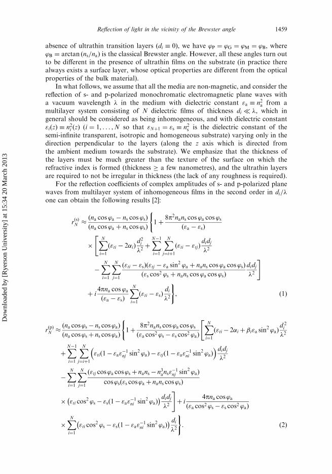
absence of ultrathin transition layers (di � 0), we have ’P ¼ ’G ¼ ’M ¼ ’B, where’B ¼ arctan ðns=naÞ is the classical Brewster angle. However, all these angles turn outto be different in the presence of ultrathin films on the substrate (in practice therealways exists a surface layer, whose optical properties are different from the optical
properties of the bulk material).In what follows, we assume that all the media are non-magnetic, and consider the
reflection of s- and p-polarized monochromatic electromagnetic plane waves with
a vacuum wavelength � in the medium with dielectric constant "a � n2a from amultilayer system consisting of N dielectric films of thickness di � �, which ingeneral should be considered as being inhomogeneous, and with dielectric constant
"iðzÞ � n2i ðzÞ (i ¼ 1, . . . ,N so that "Nþ1 ¼ "s � n2s is the dielectric constant of thesemi-infinite transparent, isotropic and homogeneous substrate) varying only in thedirection perpendicular to the layers (along the z axis which is directed from
the ambient medium towards the substrate). We emphasize that the thickness ofthe layers must be much greater than the texture of the surface on which therefractive index is formed (thickness � a few nanometres), and the ultrathin layers
are required to not be irregular in thickness (the lack of any roughness is required).For the reflection coefficients of complex amplitudes of s- and p-polarized plane
waves from multilayer system of inhomogeneous films in the second order in di=�one can obtain the following results [2]:
rðsÞN �
ðna cos ’a � ns cos ’sÞ
ðna cos ’a þ ns cos ’sÞ
(1þ
8p2nans cos ’a cos ’sð"a � "sÞ
�XNi¼1
ð"ti � 2�iÞd2i
�2þ
XN�1
i¼1
XNj¼iþ1
ð"ti � "tjÞdidj
�2
"
�XNi¼1
XNj¼1
ð"ti � "sÞð"tj � "a sin2 ’a þ nans cos ’a cos ’sÞ
ð"s cos2 ’s þ nans cos ’a cos ’sÞ
didj
�2
#
þ i4pna cos ’að"a � "sÞ
XNi¼1
ð"ti � "sÞdi
�2
), ð1Þ
rðpÞN �
ðna cos’s � ns cos’aÞ
ðna cos’s þ ns cos’aÞ
(1þ
8p2nans cos’a cos’sð"a cos2 ’s � "s cos2 ’aÞ
"XNi¼1
ð"ti � 2�i þ �i"a sin2 ’aÞ
d 2i
�2
þXN�1
i¼1
XNj¼iþ1
"tið1� "a"�1nj sin2 ’aÞ � "tjð1� "a"
�1ni sin2 ’aÞ
� �didj�2
�XNi¼1
XNj¼1
ð"tj cos’a cos’s þ nans � n3ans"�1nj sin2 ’aÞ
cos’sð"s cos’a þ nans cos’sÞ
� "ti cos2 ’s � "sð1� "a"
�1ni sin2 ’aÞ
� �didj�2
#þ i
4pna cos’að"a cos2 ’s � "s cos2 ’aÞ
�XNi¼1
"ti cos2 ’s � "sð1� "a"
�1ni sin2 ’aÞ
� � di�2
): ð2Þ
Reflection of light in the vicinity of the Brewster angle 1459
Dow
nloa
ded
by [
Rye
rson
Uni
vers
ity]
at 1
5:34
20
Mar
ch 2
013
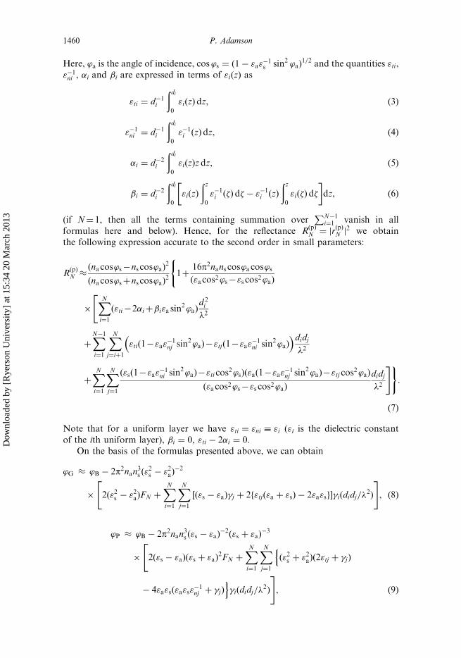
Here, ’a is the angle of incidence, cos ’s ¼ ð1� "a"�1s sin2 ’aÞ
1=2 and the quantities "ti,"�1ni , �i and �i are expressed in terms of "iðzÞ as
"ti ¼ d�1i
ðdi0
"iðzÞ dz, ð3Þ
"�1ni ¼ d�1
i
ðdi0
"�1i ðzÞ dz, ð4Þ
�i ¼ d�2i
ðdi0
"iðzÞz dz, ð5Þ
�i ¼ d�2i
ðdi0
"iðzÞ
ðz0
"�1i ð�Þ d� � "�1
i ðzÞ
ðz0
"ið�Þ d�
� �dz, ð6Þ
(if N¼ 1, then all the terms containing summation overPN�1
i¼1 vanish in allformulas here and below). Hence, for the reflectance R
ðpÞN ¼ jr
ðpÞN j2 we obtain
the following expression accurate to the second order in small parameters:
RðpÞN �
ðna cos’s�ns cos’aÞ2
ðna cos’sþns cos’aÞ2
(1þ
16p2nans cos’a cos’sð"a cos2’s�"s cos2’aÞ
�
"XNi¼1
ð"ti�2�iþ�i"a sin2’aÞ
d 2i
�2
þXN�1
i¼1
XNj¼iþ1
"tið1�"a"�1nj sin
2’aÞ�"tjð1�"a"�1ni sin
2’aÞ� �didj
�2
þXNi¼1
XNj¼1
ð"sð1�"a"�1ni sin
2’aÞ�"ti cos2’sÞð"að1�"a"
�1nj sin
2’aÞ�"tj cos2’aÞ
ð"a cos2’s�"s cos2’aÞ
didj
�2
#):
ð7Þ
Note that for a uniform layer we have "ti ¼ "ni � "i ("i is the dielectric constantof the ith uniform layer), �i ¼ 0, "ti � 2�i ¼ 0.
On the basis of the formulas presented above, we can obtain
’G � ’B � 2p2nan3s ð"2s � "2aÞ
�2
�
"2ð"2s � "2aÞFN þ
XNi¼1
XNj¼1
½ð"s � "aÞ�j þ 2f"tjð"a þ "sÞ � 2"a"sg��iðdidj=�2Þ
#, ð8Þ
’P � ’B � 2p2nan3s ð"s � "aÞ�2ð"s þ "aÞ
�3
�
"2ð"s � "aÞð"s þ "aÞ
2FN þXNi¼1
XNj¼1
nð"2s þ "2aÞð2"tj þ �jÞ
� 4"a"sð"a"s"�1nj þ �jÞ
o�iðdidj=�
2Þ
#, ð9Þ
1460 P. Adamson
Dow
nloa
ded
by [
Rye
rson
Uni
vers
ity]
at 1
5:34
20
Mar
ch 2
013

’M � ’B � 2p2nan3s ð"s � "aÞ�2ð"s þ "aÞ
�3
�
"2ð"s � "aÞð"s þ "aÞ
2FN þXNi¼1
XNj¼1
ð"2s þ "2aÞð2"tj þ �jÞ � 4"2a"2s"
�1nj
n o�iðdidj=�
2Þ
#,
ð10Þ
FN ¼XNi¼1
ð"ti � 2�i þ �i"asÞðdi=�Þ2
þXN�1
i¼1
XNj¼iþ1
"tið1� "as"�1nj Þ � "tjð1� "as"
�1ni Þ
n oðdidj=�
2Þ,
ð11Þ
where
�i ¼ ½"að"ni � "sÞ þ "nið"s � "tiÞ�"�1ni , "as ¼ "a"sð"a þ "sÞ
�1: ð12Þ
For the case of one homogeneous layer that is of considerable practical interestwe have
’G � ’B � 2p2nan3s ð"2s � "2aÞ
�2½ð"s � "aÞð"1 � "aÞð"s � "1Þ þ 2"21ð"a þ "sÞ � 4"a"s"1�
� ð"1 � "aÞð"s � "1Þ"�21 d 2
1 =�2, ð13Þ
’P � ’B � 2p2nan3s ð"s � "aÞ�2ð"s þ "aÞ
�3½ð"2s þ "2aÞð2"
21 þ ð"1 � "aÞð"s � "1ÞÞ
� 4"a"sð"a"s þ ð"1 � "aÞð"s � "1ÞÞ�ð"1 � "aÞð"s � "1Þ"�21 d 2
1 =�2, ð14Þ
’M � ’B � 2p2nan3s ð"s � "aÞ�2ð"s þ "aÞ
�3½ð"2s þ "2aÞð2"
21 þ ð"1 � "aÞð"s � "1ÞÞ
� 4"2a"2s ð"1 � "aÞð"s � "1Þ"
�21 d 2
1 =�2�: ð15Þ
The expressions for the differences of the angles ’G, ’P, ’M are also simpler:
’G � ’M � ð1þ 2"s"�1a Þð’G � ’PÞ, ð16Þ
’P � ’M � 2"s"�1a ð’G � ’PÞ, ð17Þ
where
’G � ’P � 4p2n5an3s ð"s þ "aÞ
�3ð"s � "aÞ
�2XNi¼1
�iðdi=�Þ
" #2
, ð18Þ
in the general case, and
’G � ’P � 4p2n5an3s ð"s þ "aÞ
�3½ð"s � "aÞ"1�
�2ð"1 � "sÞ
2ð"1 � "aÞ
2ð19Þ
for one homogeneous layer. Consequently, the relation ’G > ’P > ’M is alwaysvalid. From equations (16)–(18) one can also conclude that in the long-wavelengthapproximation the differences of the angles considered are independent, within anaccuracy of the second order in di=�, of the manner in which films are located on thesubstrate. To illustrate this, the dependences of ’P � ’B, ’M � ’B, ’P � ’G and’G � ’M on ns for single and multiple overlayers are plotted in figure 1, where the
Reflection of light in the vicinity of the Brewster angle 1461
Dow
nloa
ded
by [
Rye
rson
Uni
vers
ity]
at 1
5:34
20
Mar
ch 2
013

refractive index of inhomogeneous films are described by one of the following
functions:
niðzÞ ¼ n0i þ ðndi � n0iÞðz=diÞg, ð20Þ
niðzÞ ¼ n0indi½ngdi � ðngdi � ng0iÞðz=diÞ�
�1=g, ð21Þ
in which n0i and ndi are the values of the refractive index at z¼ 0 and di, respectively,
and g 6¼ 0 is a particular real number.
The accuracy of equations (8)–(10) was estimated by making exact computer
calculations using general reflection formulas without expanding in terms of small
parameters. To eliminate errors in the numerical calculations of the reflection
coefficients for inhomogeneous films, we utilize two different algorithms: (i) the
classical method in which an inhomogeneous film was represented by a large set of
homogeneous layers and (ii) by the direct numerical integration of the differential
wave equation for the inhomogeneous medium [23, 24]. For example, the relative
errors vi ¼ ½ð’iÞex � ’i�=ð’iÞex, where i¼G,P,M and the exact value of the char-
acteristic reflection angle ð’iÞex was calculated numerically and ’i was obtained by
approximate expressions (8)–(10), are plotted in figure 2.
Next we show how one can employ the specific angles ’G, ’P and ’M for optical
diagnostics of ultrathin dielectric layers. First we consider the case when there is
only one homogeneous layer with unknown parameters "1 and d1 upon the substrate.
1.5 2.0 2.5 3.0 3.5 4.0
−0.5
0.0
0.5
1.0
1.5
2.0
2.5
3.0
j P− j B ,
j P− j M ,
j G−
j P (de
g.)
ns
Figure 1. Angles ’P � ’B (solid curve), ’P � ’M (dashed curve) and ’G � ’P (dashed-dottedcurve) as functions of ns for a two-film system if d1=� ¼ 5� 10�3; d2=� ¼ 1� 10�2; na ¼ 1;n01 ¼ 1:3; nd1 ¼ n02 ¼ 3:5; nd2 ¼ 1:5. Profile n1ðzÞ is described by equation (20) with g¼ 1 andprofile n2ðzÞ is described by equation (21) with g¼ 1.
1462 P. Adamson
Dow
nloa
ded
by [
Rye
rson
Uni
vers
ity]
at 1
5:34
20
Mar
ch 2
013

Then, for example, from the relation ð’P � ’BÞ=ð’G � ’BÞ one can obtain thefollowing equation for "1:
"1 ¼ A ½A2 þ 4B"asð�� P1ð"2s � "2aÞÞ�
1=2� �
ð2BÞ�1, ð22Þ
where A ¼ P1ð"2s � "2a � 4"a"sÞ � ð�� 4"a"sÞ, B ¼ ð"a þ "sÞ
�1�þ 4"as � P1ð"s þ 3"aÞ,� ¼ "2a þ "2s , "as ¼ "a"sð"a þ "sÞ
�1 and P1 � ð’P � ’BÞ=ð’G � ’BÞ. The analogousexpressions for "1 can be obtained from the relations ð’P � ’BÞ=ð’M � ’BÞ orð’G � ’BÞ=ð’M � ’BÞ.
For determining the parameters of ultrathin layers the quantities ’G � ’B,’P � ’B and ’M � ’B in combination with ellipsometric parameters can also beapplied. Indeed, if we represent the ratio of the amplitude reflection coefficients forp- and s-polarized radiation in the conventional form r
ðpÞN =rðsÞN � tanC exp ðiDÞ, where
C and D are the ellipsometric angles, then, to first order with respect to the smallparameters di=� on the basis of equations (1) and (2), for contributions �C ¼ C�C0
and �D ¼ D� D0 (C0,D0 are the ellipsometric angles of a bare substrate) of anultrathin multilayer to ellipsometric parameters, we obtain a generalization of thewell-known Drude formulas [25] to the N-layer system of ultrathin films:
�D � 4pna cos ’a sin2 ’að"s cos
2 ’a � "a cos2 ’sÞ
�1XNi¼1
�iðdi=�Þ, ð23Þ
500 1000 1500
−3
−2
−1
0
2
1
Rel
ativ
e er
ror
(%)
λ
Figure 2. Relative errors of approximate equations (8) (solid curves), (9) (dashed curves)and (10) (dashed-dotted curves) as functions of � for a two-film system if d1 ¼ 3; d2 ¼ 2;na ¼ 1; ns ¼ 2:5; n01 ¼ 1:5 (curve 1), 4 (curve 2); nd1 ¼ n02 ¼ 2:5 (curves 1 and 2); nd2 ¼ 1:5(curves 1 and 2). Profiles n1ðzÞ are described by equation (20) with g ¼ 0:5 and profiles n2ðzÞare described by equation (21) with g¼ 2. The quantities � and di are measured in arbitrarycommon units.
Reflection of light in the vicinity of the Brewster angle 1463
Dow
nloa
ded
by [
Rye
rson
Uni
vers
ity]
at 1
5:34
20
Mar
ch 2
013

if ’a 6¼ ’B (for ’a ¼ ’B, we have �D ¼ p=2) and
�C � pð"a þ "sÞ1=2
ð"s � "aÞ�1
XNi¼1
�iðdi=�Þ
, ð24Þ
if ’a ¼ ’B (for ’a 6¼ ’B the quantity �C ðdi=�Þ2). Next, for example, one can
conclude from the relation ð’B � ’GÞ=ð�CÞ2 that
"1 ¼ P2 þ 2"as ððP2 þ 2"asÞ2� 4P2"asð1þ P2ð"s þ "aÞ
�1ÞÞ1=2
�� 2ð1þ P2ð"s þ "aÞ
�1Þ
��1, ð25Þ
P2 � ð"a þ "sÞ3ð4nan
3s Þ
�1ð’B � ’GÞð�CÞ
�2� ð"s � "aÞ=2: ð26Þ
Analogously, if we use the differential reflectance �Rð�Þ1 =Rð�Þ
0 � ðRð�Þ1 � R
ð�Þ0 Þ=Rð�Þ
0 ,where R
ð�ÞN ¼ jr
ð�ÞN j2 and � ¼ p, s, then, for example, from the relation
ð’P � ’BÞ½�RðsÞ1 =R
ðsÞ0 �
�1 one can obtain that
"1 ¼ 4"a"s � � ðð4"a"s � �Þ2 þ 4�"asð"a þ "sÞ�1ð�� P4ÞÞ
1=2 �� ð"a þ "sÞ½2ð�� P4Þ�
�1, ð27Þ
P4 ¼ 8n�2s ð"a þ "sÞ
3 cos ’a cos ’sð’P � ’BÞ½�RðsÞ1 =R
ðsÞ0 �
�1� 4"a"s: ð28Þ
Note that the differential reflectance is an immediately measurable quantity becausethe relative change in the intensity of the reflected signal
�Ið�Þr1 =I ð�Þ
r0 ¼ Ið�Þr1 � I
ð�Þr0
� �.Ið�Þr0
¼ Rð�Þ1 I
ð�Þin � R
ð�Þ0 I
ð�Þin
� �.R
ð�Þ0 I
ð�Þin
� �¼ �R
ð�Þ1 =Rð�Þ
0 ,
where Ið�Þr1 and I
ð�Þr0 are the reflected intensities from the ultrathin layer and the bare
substrate (d1 ¼ 0), respectively, and Ið�Þin is the intensity of the incident light.
For reference we have included a computer simulation for the possible errors ofapproximate formulas obtained for optical diagnostics. For example, the dependenceof the relative error of the approximate expression (22) on d1=� is demonstrated infigure 3.
Next we briefly discuss the case of a multilayer structure. Let one or multiplelayers (i ¼ 1, . . . ,N � 1), whose parameters "i and di are known, already exist uponthe substrate and another layer (i¼N), whose parameters "N and dN are to bedetermined, to be deposited onto the last film (i ¼ N � 1). Then we can measurethe ellipsometric parameter �D or �C for the deposited layer (i¼N) and one of theangles ’G, ’P and ’M for the entire N-layer system. Using the formulas (8)–(10), (23)and (24) one can then calculate "N and dN.
3. Scanning angle differential reflectometry in the vicinity of the Brewster angle
In what follows we consider the neighbourhood of the Brewster angle ’B, assumingthat the angle of incidence ’a differs slightly from the angle ’B, so that the condition�’ =’B � 1, where �’ ¼ ’a � ’B, is satisfied. Let the substrate initially haveonly one non-uniform layer with i¼ 1. Then, on the basis of previous formulas,
1464 P. Adamson
Dow
nloa
ded
by [
Rye
rson
Uni
vers
ity]
at 1
5:34
20
Mar
ch 2
013

in the long-wavelength limit the relative change of the reflectance in the vicinity ofthe Brewster angle ’B, which takes place when a second layer (i¼ 2) is applied tothe first (it must be remembered that in (7) numbering of the films is opposite: for thefirst film i¼ 2 and for the second film i¼ 1), i.e. the quantity
�RðpÞ21 ð�’Þ=RðpÞ
1 ð�’Þ � ½RðpÞ2 ð’a � ’BÞ � R
ðpÞ1 ð’a � ’BÞ�=R
ðpÞ1 ð’a � ’BÞ,
where RðpÞ1 ¼ R
ðpÞ2 ðd2 ¼ 0Þ, can be expressed as
�RðpÞ21 ð�’Þ=RðpÞ
1 ð�’Þ � ð�2d2=�1d1Þð�2d2=�1d1 þ 2Þ½ �
� �2B ð�’Þ2 þ �2B ��1
, ð29Þ
�B � 2pnan3s ð"a þ "sÞ�1=2
ð"2s � "2aÞ�1�1d1
=�, ð30Þ
�i ¼ d�1i
ðdi0
½"iðzÞ � "a�½"s � "iðzÞ�"�1i ðzÞ dz
¼ ½"að"ni � "sÞ þ "nið"s � "tiÞ�"�1ni : ð31Þ
It follows from these formulas that in the long-wavelength limit near the angle ’B thequantity �R
ðpÞ21 =R
ðpÞ1 as a function of �’ is Lorentzian with a FWHM (full width at
half-maximum) equal to 2�B. Note that the exact calculations show that the relative
0.003 0.006 0.009
−4
−2
0
2
4
4
3
2
1R
elat
ive
erro
r (%
)
d1/λ
Figure 3. Relative error of equation (22) as a function of d1=� if na ¼ 1; ns ¼ 1:5 (1 and 4),2.4 (2 and 3); n1 ¼ 1:5 (3), 2.4 (1 and 4), 3.5 (2); ¼ �0:1% (1), 0 (2), 0.1% (3), 0.2% (4). is the relative error of the quantity ð’P � ’BÞ=ð’G � ’BÞ. Preceding numbers in parenthesesare curve labels.
Reflection of light in the vicinity of the Brewster angle 1465
Dow
nloa
ded
by [
Rye
rson
Uni
vers
ity]
at 1
5:34
20
Mar
ch 2
013

error of the approximate formula (29) does not exceed a few percent if the small
parameters di=� and �B=’B are no greater than a few hundredths.
The most interesting aspect associated with equation (30) is that in the long-
wavelength limit the quantity �B is proportional to the small parameter d1=� and is
completely independent of the parameters of the second layer including the small
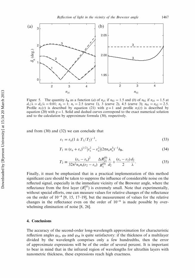
parameter d2=�. The dependence of �B on d1=� and d2=� are demonstrated in figure 4
and the dependence of �B on nd1 and n02 are demonstrated in figure 5.
At the same time, it follows from equations (23) and (24) that the ellipsometric
parameters �D and �C depend on film parameters through the quantity �1d1 as wellas the quantity �B. In other words, the method under consideration is quantitatively
fully equivalent to the ellipsometric technique because, on the basis of the formulas
(23), (24) and (30), we can determine one and the same characteristic quantity �1d1for an inhomogeneous ultrathin film. Consequently, for fully transparent layered
systems specific photometric measurements can have in principle the same sensitivity
as ellipsometry (the sensitivity of the traditional photometric differential reflectance
method is proportional to ðd1=�Þ2).
In order to determine the parameters "1 and d1 of the homogeneous ultrathin
surface layer we can deposit the second homogeneous ultrathin layer with known
dielectric constant "2 to the first layer (to the layer under investigation) and
determine its thickness d2 by ellipsometry (equation (23) or (24)). Then we can
measure �B and �Rðs, pÞ21 ð’a ¼ 0Þ=Rðs, pÞ
1 ð’a ¼ 0Þ � �Rð0Þ21 =R
ð0Þ1 , where �R
ðs, pÞ21 ¼
Rðs, pÞ2 � R
ðs, pÞ1 . Further, from (7) we obtain that
�Rð0Þ21
Rð0Þ1
�16p2nansð"a � "sÞ
22ð"a � "2Þð"s � "1Þ
d1d2
�2þ ð"a � "2Þð"s � "2Þ
d 22
�2
� �, ð32Þ
0.01 0.02 0.03 0.04
0.530
0.535
0.540
0.01 0.02 0.03 0.04
0.5
1.0
1.5
2.0
d2/λ
d B (
deg.
)(a) (b)
d1/λ
Figure 4. The quantity �B as a function (a) of d1=� if d2=� ¼ 0:01 and (b) of d2=� ifd1=� ¼ 0:01 at na ¼ 1; ns ¼ 2:5; n01 ¼ nd2 ¼ 2:5; nd1 ¼ 2; n02 ¼ 1:5. Profile n1ðzÞ is describedby equation (21) with g¼ 1 and profile n2ðzÞ is described by equation (20) with g¼ 1. Solid anddashed curves correspond to the exact numerical solution and to the calculation byapproximate formula (30), respectively.
1466 P. Adamson
Dow
nloa
ded
by [
Rye
rson
Uni
vers
ity]
at 1
5:34
20
Mar
ch 2
013
and from (30) and (32) we can conclude that
"1 ¼ "að1 T1=T2Þ�1, ð33Þ
T1 � ð"a þ "sÞ1=2 "2s � "2a
ð2pnan3s Þ�1�B, ð34Þ
T2 �ð"s � "aÞ
2
32p2nansð"2 � "aÞ
�Rð0Þ21
Rð0Þ1
�
d2þð"s � "2Þ
2
d2
�: ð35Þ
Finally, it must be emphasized that in a practical implementation of this methodsignificant care should be taken to suppress the influence of considerable noise on thereflected signal, especially in the immediate vicinity of the Brewster angle, where thereflectance from the first layer (R
ðpÞ1 ) is extremely small. Note that experimentally,
without special efforts, one can measure values for relative changes of the reflectanceon the order of 10�4 [9, 15, 17–19], but the measurement of values for the relativechanges in the reflectance even on the order of 10�6 is made possible by over-whelming elimination of noise [8, 26].
4. Conclusions
The accuracy of the second-order long-wavelength approximation for characteristicreflection angles ’G, ’P and ’M is quite satisfactory: if the thickness of a multilayerdivided by the wavelength comprises only a few hundredths, then the errorof approximate expressions will be of the order of several percent. It is importantto bear in mind that in the infrared region of wavelengths for ultrathin layers withnanometric thickness, these expressions reach high exactness.
2 3 4
1.95
2.00
2.05
2 3 4
0
1
2
3
3
3
1
2
3
d B (
deg.
)(a) (b)
nd1 n02
Figure 5. The quantity �B as a function (a) of nd1 if n02 ¼ 1:5 and (b) of n02 if nd1 ¼ 1:5 atd1=� ¼ d2=� ¼ 0:01; na ¼ 1; ns ¼ 2:5 (curve 1), 3 (curve 2), 4.5 (curve 3); n01 ¼ nd2 ¼ 2:5.Profile n1ðzÞ is described by equation (21) with g¼ 1 and profile n2ðzÞ is described byequation (20) with g¼ 1. Solid and dashed curves correspond to the exact numerical solutionand to the calculation by approximate formula (30), respectively.
Reflection of light in the vicinity of the Brewster angle 1467
Dow
nloa
ded
by [
Rye
rson
Uni
vers
ity]
at 1
5:34
20
Mar
ch 2
013

The differences between characteristic Brewster angles are independent in the
long-wavelength limit of the manner in which ultrathin inhomogeneous dielectric
films are located on the uniform isotropic substrate (the ordering of these films is
irrelevant). The relation ’G > ’P > ’M is always valid.
The analytical formulas obtained for reflection parameters in this paper are of
profound importance for the solution of the inverse problem (for determining the
parameters of nanoscopic layered structures): the application of the principal and
polarizing angles in conjunction with ellipsometric quantities or differential reflec-
tance furnishes the appropriate methods for determining the optical parameters of
nanometric multilayer structures.
The sensitivity of conventional differential reflectance methods is proportional to
the small parameter ðd1=�Þ2. But in the neighbourhood of the Brewster angle the
specific photoreflectance technique can have in principle the same sensitivity as
ellipsometry—proportional to d1=�. Such a method is rendered possible by the
measurement of the half-width of the angular spectrum of the change in the
reflectance of p-polarized light, induced by depositing a second ultrathin layer
onto the inhomogeneous surface layer under study near the classical Brewster
angle, so that only precise measurements of the change in angle, rather than an
accurate determination of the incident angle itself, will be required.
References
[1] P. Adamson, J. Opt. Soc. Am. B 20 752 (2003).[2] P. Adamson, J. Opt. Soc. Am. B 21 645 (2004).[3] L. Ward, The Optical Constants of Thin Films and Bulk Solids (Institute of Physics
Publishing, Bristol, Philadelphia, 1994).[4] A. Sammar and J.-M. Andre, J. Mod. Opt. 43 67 (1996).[5] G. Bauer and W. Richter (Editors), Optical Characterization of Epitaxial Semiconductor
Layers (Springer, Berlin, 1996).[6] I.P. Herman, Optical Diagnostics for Thin Film Processing (Academic Press, New York,
1996).[7] R.M.A. Azzam and N.M. Bashara, Ellipsometry and Polarized Light (North-Holland,
Amsterdam, 1977).[8] P. Schaaf, P. Dejardin and A. Schmitt, Langmuir 3 1131 (1987).[9] A. Dhathathreyan, U. Baumann, A. Muller and D. Mobius, Biochim. Biophys. Acta 944
265 (1988).[10] R.C. Maclaurin, Proc. R. Soc. (London) A 76 49 (1905).[11] J. Lekner, Theory of Reflection of Electromagnetic and Particle Waves (Martinus Nijhoff,
Dordrecht, 1987).[12] M.T. Haarmans and D. Bedeaux, Thin Solid Films 258 213 (1995).[13] M. Fauchet, IEEE J. Quantum Electron. 25 1072 (1989).[14] P.V. Adamson, Tech. Phys. Lett. 22 837 (1996).[15] A. Rosental, P. Adamson, A. Gerst and A. Niilisk, Appl. Surf. Sci. 107 178 (1996).[16] P.V. Adamson, Opt. Spectrosc. 83 154 (1997).[17] E.K. Mann, A. Bollander, L. Heinrich, et al., J. Opt. Soc. Am. A 13 1046 (1996).[18] E.A. van der Zeeuw, L.M.C. Sagis, G.J.M. Koper, et al., J. Chem. Phys. 105 1646
(1996).[19] E.K. Mann, E.A. van der Zeeuw, G.J.M. Koper, et al., J. Phys. Chem. 99 790 (1995).[20] F. Abeles, in Progress in Optics, Vol. 2, edited by E. Wolf (North-Holland, Amsterdam,
1963).[21] W.K. Burns and A.B. Lee, J. Opt. Soc. Am. 64 108 (1974).
1468 P. Adamson
Dow
nloa
ded
by [
Rye
rson
Uni
vers
ity]
at 1
5:34
20
Mar
ch 2
013

[22] P. Adamson, Third IEEE Conference on Nanotechnology, Proceedings (IEEE, Piscataway,NJ, 2003), pp. 836–839.
[23] B. Sheldon, J.S. Haggerty and A.G. Emslie, J. Opt. Soc. Am. 72 1049 (1982).[24] M. Kildemo, O. Hunderi and B. Drevillon, J. Opt. Soc. Am. A 14 931 (1997).[25] P. Drude, Lehrbuch der Optik (Hirzel, Leipzig, 1912).[26] P. Schaaf, P. Dejardin and A. Schmitt, Rev. Phys. Appl. 21 741 (1986).
Reflection of light in the vicinity of the Brewster angle 1469
Dow
nloa
ded
by [
Rye
rson
Uni
vers
ity]
at 1
5:34
20
Mar
ch 2
013