Embed Size (px)
Citation preview

67
Application of reflections
Periscope
This is the instrument used for looking over obstacles. It is made of two (2) plane mirrors inclined at
450 when they are facing each other. It is used in submarines, war tankers e.t.c.
REFLECTION BY CURVED MIRRORS
There are two types of curved mirrors
i) Concave / converging mirror (curve inwards)
ii) Convex (diverging mirror (curve outwards)
CONCAVE MIRRORS
A concave mirror is one with the reflecting/slivery surface on the inner side of the mirror. A concave
mirror is also called a converging mirror because it converges parallel rays to a point called
principal focus.
A concave mirror has a real principal focus because light actually pass through it as they converge
after reflection.

68
P - Pole of mirror
F - Principal focus
C - Center of curvature
R - Radius of curvature
F - Focal length
CONVEX MIRRORS
A convex mirror is one with the reflecting/slivery surface on the outer side of the mirror. A convex
mirror is also called a diverging mirror because it diverges parallel rays to appear like they are
diverging from point called principal focus.
A convex mirror has a virtual principal focus because light appear diverge, originate or come from it
after reflection.
Terms used
The pole (P) : is the center of reflecting surface
Center of curvature(C) .it is the center of sphere of which the mirror formed part of.
Principal axis: is the imaginary line that passes through the pole, principal focus and the
center of curvature of the mirror.
Radius of curvature (r): this is the radius of sphere of which the mirror formed part of.
OR: it is the distance between the pole of the mirror and its center curvature

69
Focal length (f) : this is the distance from the pole of the mirror to the principal focus.
i.e.
Aperture. This is the width of the mirror.
Principal focus / focal point(f):
a) For a concave mirror.
It’s a point on the principal axis where all incident rays parallel and close to the principal axis will
converge to after reflection.
b) For a convex mirror.
It’s a point on the principal axis where all incident rays parallel and close to the principal axis
appear to diverge from after reflection.
Note: F is real for a concave mirror and virtual for a convex mirror.
Real image: Is one which can be formed on the screen. It is formed by actual intersection of rays.
Virtual images: it is one which cannot be formed on the screen. It is formed by apparent inter
section of rays.
CONSTRUCTION OF RAY DIAGRAMS
Ray diagrams can be used to explain how and where a curved mirror forms images. The rays are drawn
using any two of the following 3 principal.
1. A ray parallel to the principal axis is reflected through the principal focus.
a) For a concave mirror
b) For a convex mirror

70
2. A ray through the principal focus is reflected parallel to the principal axis .
a) For a concave mirror
b) For a convex mirror
3. A ray through the center of curvature is reflected along the same path.
a) For a concave mirror
b) For a convex mirror

71
Image formation by concave mirror
The type, size and position of the image formed by a concave mirror depends centrally on the
distance of the object from the mirror.
1. Object 0 beyond C
2. Objects 0 at C
2. Object 0 between C and F
3. Object 0 at F

72
4. Object 0 between F and P
Image formation by convex mirror
No matter the position of the object from the convex mirror, the image formed is always virtual,
diminished and upright.
Image formed is virtual, diminished,
Upright (erect) and formed between F and P.
Construction of ray diagrams to scale.
Example
1. An object 4cm high is placed 30cm from a concave mirror of focal length 10cm. by
construction, find the position nature and size of the image
2. An object 3cm high is placed at angles to principal axis a concave mirror with focal length
7.5cm. if the object is 30cm from the pole, construct a ray diagram to obtain the position
size and nature of image (use a scale 1cm : 3cm)
Graph

73
Questions
1. An object 4cm high is placed 2.4cm from concave mirror of focal length 8cm. draw a ray
diagram to find the position size and nature of image. Scale 1cm = 2cm
2. An object of height 10cm is placed at a distance 60cm from a convex mirror of focal length
20cm. by scale find the image position, height, nature and magnification (scale 1cm : 5cm)
MAGNIFICATION
This is the ratio of image height to the object height.
M =
where h1 – image height, ho – object height
OR
This is the ratio of image distance from distance from the mirror to the object distance from the
mirror.
M=
where v – image distance, u – object distance
Example 1
An object 10cm high is placed at distance of 20cm from a convex mirror of focal length 10cm
i) Draw a ray diagram, locate the position of the image
ii) Calculate the magnification (1cm :5cm)

74
USES OF CURVED MIRRORS
a) Convex mirrors
They are used as driving mirror because
i) They give a wide field of view
ii) They give upright images of the object
Disadvantages
It gives a false impression of the distance of an object
The object is diminished.
b) Concave mirror
Used in head lamps , torches , parabolic mirrors
It can be used as sharing mirror
Used by dentists for magnification
Can be used in astronomical telescope (reflecting type)
Can be used as solar concentrators.
MEASURING FOCAL LENGTH OF A CONCAVE MIRROR
METHOD 1: Distant object method(rough method)
Hold a concave mirror at one end focusing t he distant object.
Hold a white screen in front of the mirror so that it receives rays reflected from it to reach the
mirror from the object.

75
Move the screen at different distances from the mirror until a sharp image is formed on the
screen
Measure the distance from the screen to the mirror with a metre rule.
Repeat the experiment several times and find the average value of the distance between the
screen and the mirror. This is the focal length (f) of the mirror
METHOD 2 : using illuminated object at c
- With the mirror facing illuminated object, adjust the distance between them until a sharp image is
formed on the screen alongside the object.
- Measure the distance between the object and the mirror
- Repeat the experiment for several attempts and find the average value. This is the radius of a
curvature so the focal length (f) is obtained from r =2f.
MIRROR FOMULA METHOD.
- Two pins are required, one acts as an object pin and the other as a search pin.
- The object pin is placed in front of the mirror between F and C so that a magnified real image
is formed beyond C.
The search pin is then placed so that there is no parallax between it and the real image as
shown in figure above.
The distance of the object pin from the mirror, u and that of the search pin, v is measured.

76
Several pairs of object and image distances are obtained in this way and the results in a
suitable table including
,
, and
A mean for focal length f is obtained from the mirror formula
o f =
REFRACTION
This is the bending of light when it passes from one medium to another of different optical densities.
P Q
PQ – Interface
O -- Point of incidence
OB – Refracted ray
AO – Incident ray
i-Angle of incidence
r- Angle of refraction
NN’ – Normal
REFRACTION can also be defined as the change in speed of light when it moves from one medium
to another of different optical densities.
N.B
When a ray of light enters an optically denser medium, it is bent towards the normal and when it
enters a less dense medium it is bent away from the normal.

77
LAWS OF REFRACTION OF LIGHT
1. The incident ray, the refracted ray and the normal ray at the point of incidence all lie on the same
plane.
2. The ratio sine of angle of incidence to the sine of angle of refraction is constant (snell’s law) for any
given pair of media
i.e. =
= constant (n) where n – refracted index of the medium containing the refracted ray.
Refractive index
It is the ratio of sine of angle of incidence to the sine of angle of refraction for a ray of light moving from
one medium to another of different of different optical densities.
Example
1. A glass material has a refractive index n= 1.5 .find the angle of refraction, if the ray of light moves
from air to glass as shown below.

78
Refractive index n =
1.50 =
Sin r =
r = sin-1[
=
EXPERIMENT TO VERIFY SNELL’S LAW
A glass block is placed on a white sheet of paper and its outline ABCD drawn as shown below.
E
- The glass block is then removed using a protractor; the normal is drawn at a point to 0
along AB and an angle of incidence i measured.
- Pins P1 and P2 are fixed on the line making an angle of I to the normal and the glass block
replaced on its outline ABCD.
- While looking through side CD, two other pins p3 and p4 are fixed so as to appear in lines of
images p1 and p2.
- The glass block, pins p3 and p4 are removed and a line drawn through points where p3 and
p4 were fixed. This line is called the emergent ray. It is drawn through 0 to meet CD at E.
- Point 0 is joined to E. The line is called the refracted ray.
- The angle of refraction r is measured.
- The experiment is repeated using other angles of incident 20, 30, 40, and 50.
- The values of i, r are tabulated as shown.
i/0 r/0 Sin i Sin r
10
20
30
40
50
A graph of sin i against sin r is plotted. A straight line graph through the origin verifies Snell’s law.

79
NB: The slope of the graph gives the refractive index of the glass
Slope n =
Absolute refractive index
Is the ratio of sine of angle of angle of incidence to the sine of angle of refraction for a ray of light
moving from air (vacuum) to another medium of different optical density.
n =
the angle incident i should in air or vacuum.
REFRACTION ON PLANE PARALLEL BOUNDARIES
The refractive index of n of the medium is denoted by 1n2 for a ray of light moving from medium 1 to
medium 2.The refractive index of a ray of light moving from glass to water is written as g w =
where ng and nw are absolute refractive indices of glass and water respectively. So 1n2 =
=
n1sin i = n2 sin r
Principal of reversibility of light
It states that when the direction of ray of light is reversed, it follows exactly the same path as before.
a g
(i)
g a =
(ii)
a g =
or g a =
Question

80
Figure above shows a glass slab of uniform thickness, lying horizontally. Above it is a layer of water.
A ray of light PQ is incident upwards on a lower surface of the glass and is refracted
successively at A, B and C, the points where it crosses the interfaces. Calculate
(i) angle x,
(ii) angle y, and
(iii) the refractive index for light passing from the water to glass. (Refractive indices of glass and
water are 3/2 and 4/3 respectively.)
EFFECTS OF REFRACTION ON PLANE SURFACES
Refraction on plane surface causes
- a partially immersed stick in water at an angle to appear bent at the boundary between
air and water.
- A stick placed upright in water appears shorter
- A swimming pool or well or pond appears shallower than it’s actual size
- An object placed under the glass block appears nearer
Explanation of the effects of refraction
Rays of light from point B on the stick move from water to air i.e. from a dense medium to a less
dense medium. On reaching the surface of water, they are bent away from the normal. On

81
entering the eye of the observer, rays appear to come from point C which is the image of B on
the object.
REAL AND APPARENT DEPTH
An object 0 placed below a water surface appears to nearer to the top when viewed from above .
the depth corresponding to apparent depth
The actual depth of an object, below the liquid surface is called the real depth.
Relationship between real apparent depth and refractive index
Refractive index n =
Using the principal of reversibility of light sin i =
, sin r =
n=
=
X
n=
if B is close to A, BO =A0 and BI = AI
n =
but A0 is the real depth

82
AI is the apparent depth
Hence n =
Examples
1. A swimming pool appears to be only 1.5m deep. If the refractive index of water is 4/3 calculate the
real depth of water in the pool.
n =
4/3 =
r =
= 2.0m
2. A coin is placed at the bottom of the beaker which contains water at a depth of 8cm. how much
does the coin viewed from above appears to be raised ( take n to be 4/3 )
Question
1. A pin at the bottom of the beaker containing a transparent liquid at a depth of 24cm is apparently
displaced by 6cm. Calculate the refractive index of the liquid.
Determination of refractive index by real and apparent depth method
A glass block placed vertically over a cross (x) drawn on a white sheet of paper as shown above.
A pin is clamped on a sliding cork adjacent the block, it is moved up and down until there is no
parallax between it and the image of the cross (x) seen through the block.
The real depth and apparent depth x are measured and the refractive index is then calculated from

83
n =
Determination of refractive index using a triangular prism
A prism is placed on a white sheet of paper and it’s outline drawn as shown below.
Two object pins p1and p2 are fixed upright on side AC and while looking through the prism for side
AB, two other pins p3 and p4 are fixed such that they appear to be in line with images of P1 and
P2, the prism is removed, a line drawn through P1 and P2 another drawn through P3 and P4.
Points M and N are joined by a straight line and normal ST drawn at a point M as shown. Angle i
and r are measured
The procedure is replaced to obtain different values of i and r and the results tabulated as shown.
i/0 r/0 Sin i Sin r
- - -
- - -
- - -
A graph of sin i against sin r is plotted. The slope of the graph is the refractive index of the prism.
DEVIATION THROUGH PRISMS
A mono chromatic light incident on a prism changes its direction (deviates) as it is entering the prism
as shown.
84
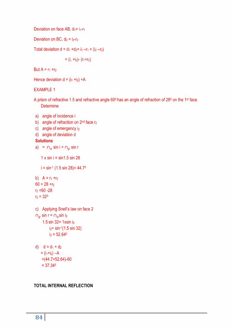
Deviation on face AB, d1= i1-r1
Deviation on BC, d2 = i2-r2
Total deviation d = d1 +d2= i1 –r1 + (i2 –r2)
= (i, +i2)- (r1+r2)
But A = r1 +r2
Hence deviation d = (i1 +i2) +A
EXAMPLE 1
A prism of refractive 1.5 and refractive angle 600 has an angle of refraction of 280 on the 1st face.
Determine
a) angle of incidence i
b) angle of refraction on 2nd face r2
c) angle of emergency i2
d) angle of deviation d
Solutions
a) = sin i = sin r
1 x sin i = sin1.5 sin 28
i = sin-1 (1.5 sin 28)= 44.70
b) A = r1 +r2
60 = 28 +r2
r2 =60 -28
r2 = 320
c) Applying Snell’s law on face 2
sin r = sin i2
1.5 sin 32= 1xsin i2
i2= sin-1(1.5 sin 32)
i2 = 52.640
d) d = d1 + d2
= (i1+i2) –A
=(44.7+52.64)-60
= 37.340
TOTAL INTERNAL REFLECTION

85
This is the phenomenon by which all light travelling from an optically dense medium to a less dense
medium is reflected back in the dense medium, when the angle of incidence in the dense
medium is greater than the critical angle.
Conditions for total internal refraction to occur
Light should travel from an optically dense medium to a less dense medium
The angle of incidence in the dense medium should be greater than the critical angle.
How does total internal reflection arise?
Consider a ray of light in the dense medium for which the angle of incidence is less than the critical
angle , the ray produces a weak reflected ray and a strong reflected ray as shown in (i)
When the angle of incidence is increased to a critical angle, the angle of refraction is 900
Critical angle c: this is the angle of incidence in a more optically dense medium for which the angle
of reflection is 900
When the angle of incidence is increased beyond the critical angle, total internal reflection occurs as
shown below in (ii)

86
Relationship between Refractive index and critical angle.
Applying Snell’s law at the interface,
ng sin c = na sin 90 =1
ng =
Example:
1. Find the critical angle of a medium of reflective index 1.5
Sin C =
C =sin-1(
) = sin-1(
= 41.80
APPLICATION OF TOTAL INTERNAL REFLECTION
In reflecting prisms which are in binoculars, periscopes and cameras e.g i) Turning a ray through
900
Prism periscope


