Embed Size (px)
Citation preview
Refining Mechanisms and Development of TMP Properties in a Low-Consistency Refiner Oddbjørn Eriksen1 and Lars-Åke Hammar2
1PFI - Paper and Fibre Research Institute, NO-7491 Trondheim, e-mail: [email protected] 2STFI-Packforsk, SE-11486 Stockholm, e-mail: [email protected] ABSTRACT First stage high-consistency (HC) mechanical pulps of Norway spruce (Picea abies) were processed in a low-consistency (LC) refiner in order to reduce the total energy consumption without sacrificing pulp quality properties. The present study has shown that the main difference between the low- and high-consistency pulps was that the low-consistency pulps contained a smaller fraction of long fibres compared to the high-consistency pulps. It was possible to increase the tensile index with 10 units in only one pass LC refining in such a way that the tensile index reached a level which was comparable with TMP from a secondary mill refiner. The two-stage HC-LC layout for treatment of coarse mechanical pulp is mainly a concept in research due to lack of control mechanisms of low-consistency refiners. The operation of the LC refiners is demanding due to a narrow operating window, with a plate gap down to a few fibre widths. The plate clearance in a high-consistency refiner is several times larger. The need to control the process operation is essential in order to create a pulp of desired quality. Thus, it is necessary to collect more information from the process. The topical information of interest is associated to the gap clearance and the flow phenomena as well as the fibre coverage of the bars and the stresses applied to the fibres. The present investigation has combined the objective of lower energy consumption at maintained pulp quality with an objective to increase the fundamental comprehension of what is happening in the refining zone. The latter is sought by experimental research associated to gap, vibration and pressure measurements. Only through basic understanding of the real mechanisms it is possible to design and control the fibre treatment process. INTRODUCTION Research and development in the area of mechanical pulping has undoubtedly had focus on high-consistency refining the last decades. Low-consistency refining in mechanical pulping has gradually found its place in post or rejects refining [1, 2]. Recently, more attention has been addressed towards LC refining at an earlier stage in the mechanical pulping line, due to a general agreement that low-consistency refining of mechanical pulp is an energy-effective technique for fibre processing. The refining concept developed at STFI-Packforsk combines the high- and low-consistency refining in a two-stage HC-LC process [3]. The process combines effective defibration of chips to fibres in a high-consistency refiner and further refining of the defibrated fibres at low-consistency conditions. To reduce the heat losses LC refining is chosen as a secondary refining stage in contrast to the use of two high-consistency stages as in conventional TMP. The low-consistency refining offers a potential way of reducing the energy consumption. It is important also in the LC stage to soften the fibre material by heat to avoid severe fibre shortening. The structure of the rigid lignin is softened if the temperature is high enough. Low-consistency refining of high freeness mechanical pulp is an unconventional technique applied in the mechanical pulping process. Thus, with a view to develop the process even further, this technique has potential to gain more by less efforts compared to the traditional TMP process. It is a matter of fact that conventional refiner plates for LC refining are designed for chemical pulps. The quality of low-consistency mechanical pulp will definitely be improved by optimizing refiner plates for this purpose. However, more knowledge is needed to optimize the refining conditions for low-consistency mechanical pulp. The rapid growth of sensors and data acquisition equipment that has taken place the last years offers an opportunity to increase the desired knowledge. Basically, all prevailing knowledge of flow mechanisms in low-consistency refiners comes from studies made on the beating process of chemical pulps. A short review of existing models and flow phenomena concerning low-consistency refining in general have to include Page’s [4] and Ebeling’s [5] assessments of the beating of chemical pulps. Also reflections by Fahey [6] should still be considered as relevant. Page strongly claimed that it is the solid
fibre phase that transmits the forces across the beating gap while the hydrodynamic forces control the presentation and arrangement of the fibres in the beating zone. This is obviously supported by the fact that work of beating is far greater than the work of circulating the beater roll without stock at the same gap. Page also emphasized that the factors that affect the mechanical rather than the hydro-dynamical forces such as friction of the bar or the shape of the bar edge, are known to have substantial effect on the beating action. Page concluded that a mechanistic theory of the beating action is missing. His opinion was that a theory should be made in terms of the stresses that fibres experience in the beating zone, and their response to those stresses. Thus, direct measurements in the refining zone have been strongly appreciated in order to measure the actually stresses. Nordman and co-workers [7] were pioneers when they conducted plate clearance measurements in LC refiners using an eddy-current sensor. A main conclusion of their work was that the plate clearance was especially sensitive to changes in the rotational speed of the refiner. However, they could not establish a relationship between the bar clearance and the pulp quality. They stated nevertheless that the gap mainly was too high to assume that single fibres could be trapped between the bars on the opposite discs. Thus, they concluded that if fibres receive some kind of compressive mechanical treatment in refining then the fibres appear in bundles or flocs of fibres. They found it also challenging to establish a real zero-point. Therefore the zero-point was measured as a post-operation after each refining trial by forcing the rotor disc towards the stator disc until metallic contact was obtained. Disc clearance sensors are more or less established technology in high-consistency refining. Today, relative gap changes can be measured. However, there are still a lot of uncertainties associated to gradual wear and offset values. The foremost studies connected to gap measurements in mill-scale refiners were done 25 years ago [8]. Thereafter, Dahlqvist and Ferrari [9] and Jackson et al. [10] introduced mill-scale studies using the true disc clearance (TDC) sensor for supervision of the refiner plate gap. As a counterpart to the present study, Mohlin [11, 12] reported results from pilot-scale studies with LC refiners where the adjustable gap sensors (AGS) were tested during refining of chemical pulps. She stated that the plate clearance is a favourable variable to compare refining results compared to the theoretical term refining intensity. A few attempts have been performed to measure forces or pressures in low-consistency refiners. Russian researchers at the Pulp and Paper Research Institute in former Leningrad were pioneers when they reported force measurements in low-consistency refiners 30-35 years ago [13-15]. It was shown that the results of the beating process were determined by the pressure exerted on the frontal part of the working surfaces of the bars covered by a layer of fibres. The pressure reached up to 35 bars (3.5 MPa) in the first part of the bar when the refining was conducted with a specific edge load of 1.5 Ws/m. The type of pulp was an unbleached sulphite pulp. Results from the pilot trial were confirmed in an industrial scale refiner as well. Table data indicate that the pressure reached even higher in an industrial refiner. The pressure decreased rapidly after 2-3 mm of the bar width and levelled out at only 10-15 % of the maximum pressure. The maximum pressure was 13 times higher than the calculated average pressure assuming that the total bar surface was utilized in refining [15, 16]. The motivation for the ongoing study was to elucidate the behaviour of the pulp flow through the refining zone, and thus, gain fundamental knowledge of the flow mechanisms and fibre treatment. First stage high-consistency mechanical pulps were processed in the low-consistency disc refiner which functioned as a second stage in the modified TMP line. The development of the pulp and fibre properties was carefully examined as a measure of the process conditions. Several different types of pulp were tested as a result of the process monitoring activity, and several different refiner plate sets were run in order to evaluate the development of the pulp properties. In addition, this presentation focuses on the measurement techniques that were applied in the low-consistency disc refiner at the EuroFEX pulp mill facilities at STFI-Packforsk. Different sensors as plate gap sensors, accelerometers for vibration analyses and fibre-optics pressure sensors have been applied in this study. The initial objective of the last part of this study was to investigate the performance of the fibre-optic sensors in order to find coherences between the pressures and the operational conditions as well as the pulp properties. However, the complexity of the measurements and the comprehensive amount of data made it necessary to restrict the scope of work. In this state of the work it was important to investigate the performance of the pressure sensors and derive whether the sensors were appropriate for this purpose. The objective was to verify the measurements and contribute to develop a final version of the sensor that gives reproducible recordings.

MATERIALS AND METHODS The refiner used in the present study was a 600 mm (24 inches) Beloit Jones Double-D 4000 refiner. The refiner motor is frequency controlled in order to allow variable speed. The refiner is driven by a 322 kW DC motor.
Figure 1. The sketch shows the Beloit Jones DD 4000 refiner (Source: Booklet from Beloit Corp., MA, USA). The refiner has two flat stationary discs and a double-sided rotor disc in between. The rotor disc is movable on a spline shaft. The stator disc on the tail-end of the refiner is movable by a frequency controlled motor. The rotor is assumed to be equally balanced and positioned in the middle between the stator discs by the input flow of pulp suspension. The refiner was operated as a single pass refiner. The refiner system is equipped with flow and pressure controls. In addition, temperatures of the pulp suspension in and out of the refiner were measured and recorded together with other process variables in a distributed control system (DCS) provided by ABB. Experimental This study incorporated three different trials. The main difference between the trials was the use of different refiner plates. Five sets of refiner plates were tested. The refining series were primarily accomplished with first stage high-consistency mechanical pulps.
A B
Pump Refiner
Heatexchanger
SamplevalveA B
Pump Refiner
Heatexchanger
Samplevalve
Figure 2. LC refining loop of the EuroFEX pilot mill.

The mechanical pulps were collected at high-consistency conditions at actual mills. Water was heated to 95 ºC prior to the dilution of the pulp. The heating of water was accomplished separately in order to reduce negative influence on the fibres during a long heating process. The consistency of the diluted pulp was initially set to 3.5 %. The stock was stirred in 20 minutes to disintegrate the fibres prior to the refining. The refining was conducted as a one-pass run through pumping of the pulp from one storage chest to another. Samples of the pulp were taken out from a sample-valve during the refining. Figure 2 shows the refining loop of the pilot mill, while Table 1 shows the prevailing process conditions during the different trials. Table 1. Conditions in the LC refining. Type of input pulp (trial 1) TMP primary: 400-430 ml CSF, TMP secondary: 120-130 ml CSF Type of input pulp (trial 2) TMP primary: 420 ml CSF Type of input pulp (trial 3) TMP primary (RTS): 335 ml CSF Consistency, % ∼3.5 Temperature, °C ∼90 Rotational speed, rpm 700 (trial 1 and 3), 700 and 900 (trial 2) Flow rate, l/min 200-900 Specific edge load (SEL), Ws/m 0.3, 0.5, 0.7 and 0.9 Edge length, km/rev (trial 1) 8.4 and 15.7 Edge length, km/rev (trial 2) 18.6 and 6.1 (full surface dams) Edge length, km/rev (trial 3) 8.5
Measurement equipment Vibration measurements were performed by the use of an accelerometer, Brüel & Kjær type 4384, attached to the refiner housing. It was used together with a corresponding charge amplifier (Brüel & Kjær type 2635) and a high-speed data acquisition unit from National Instruments Corp. (NI-6115). During the measurements, the amplifier was located a short distance of some 2-3 metres from the accelerometer. Recordings of the axial vibrations of the refiner housing were made when the accelerometer was attached to the refiner housing on the movable stator disc. The accelerometer was attached to the refiner using a magnet and an attachment screw. The position of the accelerometer was close to the gap clearance sensor. The data acquisition system was also located close to the refiner. Mainly, a sample rate of 500.000 samples per second (500 kS/s) was used to record the vibration signal.
”True Disc Clearance” Sensor
Step motor plus gear
AGS-position (APO): Zero when sensor-tip is in plane with fixed
t
Position Sensor
Fixed Fillings (Segments) Moving Fillings
(Segments)
APO-Ref.point: mechanical stop position”
Gap Clearance (disc gap) to be measured
Vibration picup
xD
Figure 3. The functional set-up of the AGS-sensor.
The plate clearance measurements were acquired by use of two sensors, located in each of the stator discs. The sensors were provided by Dametric AB. Their adjustable gap sensor (AGS) is an automatic on-line self calibrating sensor for refiners. The sensor is a modified True Disc Clearance (TDC) sensor. The measuring principle of the AGS-sensor is based on magnetic reluctance measurements. It is combined with a special positioning system to define the zero-point. Figure 3 displays the functional arrangement of the AGS sensor.

Six fibre-optic pressure sensors from Luna Innovations, Inc. were tested in the third trial. The sensors were mounted into the stator plates manufactured by J&L Fiber Services, Inc. through small holes of approximately 1.9 mm in diameter. The sensor surface was mounted almost in plane with the top of a single bar with direct contact to the pulp suspension in the plate gap. The sensing surface of the fibre-optic pressure transducers was approximately 1 mm in diameter, while the outer diameter of the transducer housing was 1.6 mm. The transducers are called EFPI fibre-optic strain sensors. EFPI is the abbreviations for Extrinsic Fabry-Perot Interferometer because the sensor is based on interference between reflected light waves. The signal from the interferometer is a sinusoidal function of the pressure applied on the sensor surface. The sensors provided for this study were made such that the sinusoidal pattern was not predominant. In other words, the linear pressure range of the sensors was high so that the prevailing pressures in the refining zone were solely connected to one monotonically leading or trailing edge of the sinusoidal relationship. This was in contrary to the transfer function curves of similar sensors provided for a study in a high-consistency refiner [17, 18]. The present data recordings were performed using the high-speed DAQ-card (NI-6115) with a resolution of 12 bits. The typical sampling rate was 1 MSamples/second. RESULTS AND DISCUSSION These trials have revealed that it was possible to increase the tensile index with 10 units in only one pass low-consistency refining. The tensile index of the second stage low-consistency pulp was then comparable with a secondary stage high-consistency pulp. Figure 4a shows that an edge load of 0.5 Ws/m increased the tensile index easier compared to higher edge loads. An energy input of 200 kWh/tonne raised the tensile index of the pulp from 29 to almost 40 Nm/g. The fibres were cut when the edge load was too high. Compared at the same tensile index, the corresponding energy consumption was approximately 500 kWh/tonne for the high-consistency pulp. Thus, the energy reduction was approximately 20 % based on the total specific energy consumption of some 1500 kWh/tonne after two stages of high-consistency refining.
Figure 4. (a) The tensile index of handsheets from low-consistency pulps can reach the same level as high-consistency pulp (mill reference) if the low-consistency refining is strictly controlled. (b) The Bauer McNett analysis of the secondary HC pulp (HC-HC) and the LC pulp (0.5 Ws/m) (HC-LC) of corresponding tensile index shows that LC refining influenced the distribution of the fractions. These results were obtained in trial 3. The main difference between the low- and high-consistency pulps was that the low-consistency pulp contained a smaller fraction of long fibres compared to the high-consistency pulp i.e. mill reference. A study of the Bauer McNett fractions showed that the long fibre fraction (>16) was shifted towards the subsequent fractions (16-30 and 30-50). The amount of fines was more or less similar in the two pulps. Figure 4b shows the Bauer McNett analysis of the two pulps of almost equal tensile index. The handsheets made from low-consistency pulps was typically 30-50 kg/m3 denser than the high-consistency reference pulp at similar tensile index. The latter was probably due to the shift in fibre distribution. The measurements of the plate clearances seem to give valuable information of the refining conditions. In addition, the experience is that the uncertainty in zero-point setting is much less for the AGS system compared to what can be achieved with an external position sensor i.e. original gap displacement sensor. The impression is that both types of

measurements give an accurate measure of the relative shift in gap clearance during operation. As a measure of the close relationship between the gap clearance and other process variables a few examples are shown.
Figure 5. (a) The plate clearance i.e. average value of the two refining zones had a strong relationship to the specific energy consumption as well as the specific edge load. (b) The relationship between the plate clearance and the light scattering coefficient shifted direction at a plate gap corresponding to approximately 250 µm. These data were captured in trial 3. Figure 5a shows that the gap measures were strongly correlated with the specific energy consumption. The gap measures indicate that the clearance between the stator and rotor discs during normal production was rather high compared to previous assumptions of gaps smaller than 100 µm. A comparison between Figures 4a and 5a reveals that best pulp strength development in trial 3 was obtained when the plate clearances on average were some 250- 300 µm. This level of plate clearance seemed to be a transition region for the pertinent trial conditions. Other pulp quality variables had a deflection angle in this region too. The relationships between the plate clearance and the light scattering coefficient changed direction as observed in Figure 5b. The general impression is that the LC refining gives an opportunity to reduce the total energy consumption without radically loosing any of the desired mechanical pulp quality properties. However, it is important to combine a suitable edge load and refiner plates in order to obtain the pulp strength properties. Refining of primary and secondary high-consistency softwood pulps with plates of medium edge length (approximately 8.5 km/rev) at a low edge load of 0.5 Ws/m maintained the long fibre content better than a finer plate pattern or higher edge loads. Refining of second stage pulps with refiner plates with narrow bar widths (edge length of 15 and 18 km/rev) at a low edge load of 0.3 Ws/m was also found to be a good combination for LC refining. The plate pattern seems to be of high importance when selecting the right refining conditions for mechanical pulp in a low-consistency refiner. Refiner plates for long fibre chemical pulps are probably not a good choice for this purpose, and special plate pattern should be designed for mechanical pulps. The latter is supported by Goncharov [15] who claimed that the operative width of the bars should be approximately equivalent to the average fibre length of the pulp to be treated in order to treat the maximum number of fibres per unit available area of the beating zone [16]. Two unequal refining zones It is reasonable to question the equality of the running conditions in the Beloit refiner due to an observed asymmetrical position of the rotor disc. The present investigation has revealed that the refiner was not working ideally all the time. The twin-concept with two refining zones and a floating rotor disc did not always give similar refining conditions in the two refining zones. The rotor is assumed to be equally balanced and positioned in the middle between the stator discs by the input flow of pulp suspension. This was not generally observed by the plate gap measurements in the two refining zones. Figure 6 shows one example of the difference in the plate gap between the refining zones. The figure demonstrates that the two gaps were almost equal at the largest gap clearance i.e. lowest energy consumption, whereas the subsequent progress at higher loads deviated considerably. The measured difference between the two plate gaps was some 0.05-0.10 mm. This signifies that the refining conditions were not equal in the two zones at higher loads. The

rotor was apparently not floating properly in between the two stator discs. It is assumed that the friction between the spline on the rotor disc and the spline shaft caused the imbalance. Another possibility is that the inequality of the gap displacement was caused by different amount of pulp in the two refining zones. If so, the refining energy may likely be distributed more evenly by the different gap clearances. However, it remains to be demonstrated that the uneven gap clearances are compensated by different amount of pulp in the two refining zones. Since the refined pulps were merged in the peripheral casing of the refiner without separate pulp sampling units, it was not possible to determine whether the properties of the two partial pulps were different. Figure 6. The plate clearances in the two refining zones of the Beloit DD refiner shows that the gap sizes differed considerably. This was observed in trial 3. The tear indexes represent the corresponding joint pulp samples. The slopes of the regression curves in Figure 6 are not equal, which indicates that the movement of the rotor was affected by other factors than the axial thrust. Different amounts of pulp in the two refining zones may have contributed to the inequality of the gap displacement during influence of a movable stator disc. Thus, it can be assumed that the double disc concept introduces an additional dimension when it comes to the uncertainty associated to refining behaviour and flow phenomena. Subsequently, the homogeneity of the pulp quality can be questioned. Vibrations Figures 7a and 7b show the relationship between the sum of gap clearance measures and the overall vibration level represented with the standard deviation of the recordings from the accelerometer.
Figure 7. The relationship between the gap clearance measures and the vibrations of the refiner housing is shown for different specific edge load values (a) and different flow rates (b). The data in Figures 7a and 7b collected in trial 3 as well. The adaptation of the fitted curve to all of the data points gave an optimum at a gap clearance of approximately 200 µm i.e. the sum of gap clearances was approximately

400 µm. Based on the pulp quality analyses, Figure 4a, the highest tensile indexes were obtained when the refining conditions corresponded to specific edge loads of 0.5 and 0.7 Ws/m. At the same time, the flow rates were 200 and 300 litres per minute. The matching process properties, here represented by the vibrations of the refiner housing, are associated with the points that had a vibration level below the fitted curves in Figures 7a and 7b. Thus, a low vibration level seems to be synonymous with a desired process stability and refining performance. Another approach concerning the vibration measures is associated with the frequency information of the recordings. Figure 8 shows frequency information subtracted from recordings from two different process conditions which in turn were related to the quality of the corresponding pulp samples. The assessment of the relationship is that the best pulp quality, represented by the tensile index of the handsheet, was obtained when the vibration level i.e. the height of the frequency peaks, was relatively small. In addition, the refining performance seemed to give the best pulp quality when the dominating peaks in the frequency spectra corresponded to the bar movement of the bars located close to the periphery. Both of these factors are fulfilled in the upper frequency spectrum of Figure 8. The latter indicates that the main refining action took place in the outer part of the refining zone. Such assumption may be associated to observations by Banks [19] who found that more flocs of fibres were accumulated in the peripheral part of the refining zone. The lower spectrum indicates that the main refining area was shifted closer to the centre of the refining zone since the dominating frequency peak corresponded to a smaller number of rotor bars compared to the number of bars at the periphery. However, the lower frequency spectrum shows also frequency peaks which can be associated with the impact of fibrous material at the plate periphery. The latter may be explained by the fact that the accelerometer picks up vibrations independent of origin. Thus, the vibrations generated in the other side of the refiner may have contributed to the overall vibration level and were thus appearing in the frequency spectrum. The vibrations from each side were probably not similar. The gap clearances indicate that the refining performance was different in the two refining zones.
Figure 8. Vibrations of the refiner housing recorded at different process conditions are related to the pulp quality of the corresponding pulp samples. These vibrations were recorded during trial 1.
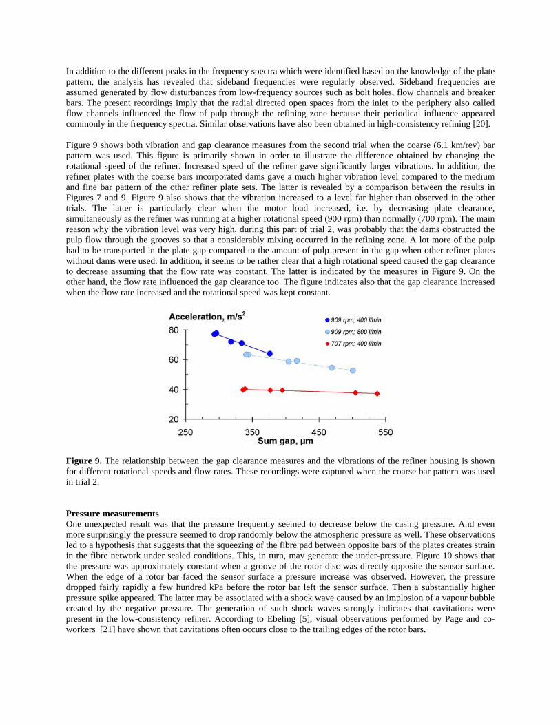
In addition to the different peaks in the frequency spectra which were identified based on the knowledge of the plate pattern, the analysis has revealed that sideband frequencies were regularly observed. Sideband frequencies are assumed generated by flow disturbances from low-frequency sources such as bolt holes, flow channels and breaker bars. The present recordings imply that the radial directed open spaces from the inlet to the periphery also called flow channels influenced the flow of pulp through the refining zone because their periodical influence appeared commonly in the frequency spectra. Similar observations have also been obtained in high-consistency refining [20]. Figure 9 shows both vibration and gap clearance measures from the second trial when the coarse (6.1 km/rev) bar pattern was used. This figure is primarily shown in order to illustrate the difference obtained by changing the rotational speed of the refiner. Increased speed of the refiner gave significantly larger vibrations. In addition, the refiner plates with the coarse bars incorporated dams gave a much higher vibration level compared to the medium and fine bar pattern of the other refiner plate sets. The latter is revealed by a comparison between the results in Figures 7 and 9. Figure 9 also shows that the vibration increased to a level far higher than observed in the other trials. The latter is particularly clear when the motor load increased, i.e. by decreasing plate clearance, simultaneously as the refiner was running at a higher rotational speed (900 rpm) than normally (700 rpm). The main reason why the vibration level was very high, during this part of trial 2, was probably that the dams obstructed the pulp flow through the grooves so that a considerably mixing occurred in the refining zone. A lot more of the pulp had to be transported in the plate gap compared to the amount of pulp present in the gap when other refiner plates without dams were used. In addition, it seems to be rather clear that a high rotational speed caused the gap clearance to decrease assuming that the flow rate was constant. The latter is indicated by the measures in Figure 9. On the other hand, the flow rate influenced the gap clearance too. The figure indicates also that the gap clearance increased when the flow rate increased and the rotational speed was kept constant. Figure 9. The relationship between the gap clearance measures and the vibrations of the refiner housing is shown for different rotational speeds and flow rates. These recordings were captured when the coarse bar pattern was used in trial 2. Pressure measurements One unexpected result was that the pressure frequently seemed to decrease below the casing pressure. And even more surprisingly the pressure seemed to drop randomly below the atmospheric pressure as well. These observations led to a hypothesis that suggests that the squeezing of the fibre pad between opposite bars of the plates creates strain in the fibre network under sealed conditions. This, in turn, may generate the under-pressure. Figure 10 shows that the pressure was approximately constant when a groove of the rotor disc was directly opposite the sensor surface. When the edge of a rotor bar faced the sensor surface a pressure increase was observed. However, the pressure dropped fairly rapidly a few hundred kPa before the rotor bar left the sensor surface. Then a substantially higher pressure spike appeared. The latter may be associated with a shock wave caused by an implosion of a vapour bubble created by the negative pressure. The generation of such shock waves strongly indicates that cavitations were present in the low-consistency refiner. According to Ebeling [5], visual observations performed by Page and co-workers [21] have shown that cavitations often occurs close to the trailing edges of the rotor bars.

Figure 10. A series of rotor bars is superimposed on one recording of the pressure. The symmetrical behaviour of the pressure progress supports the assumption that under-pressure may be present in low-consistency refiners. The shock wave generation should not be as evident as they were if the under pressure was not below a certain value. The vapour pressure of water is determined by the temperature. Refining of mechanical pulps at high temperature (85-95°C) exposes the refining process to easier becoming affected by undesirable cavitations compared to the refining of chemical pulps at cold conditions. The pressure drop needed at 85-95°C is only some 15-40 kPa below atmospheric pressure. Figure 11 is made to illustrate the current observations and to form a hypothesis of what happens in the plate gap. The small part of the current recording consists of approximately 200.000 samples corresponding to the duration of one bar and groove passage. The assumed build-up of fibres on the leading edge of the rotor bar and the bar surface is illustrated. The measures in this sketch are done accordingly to the scale values. Thus, the clearance between the bars of the stator and rotor discs (150 µm) is scaled to correspond to the width of the rotor bar (3.0 mm). Since the pressure recording is seen from the stator side it is necessary to evaluate the relative movement, i.e. the stator moves while the rotor stands still. That is why the width of the stator bar is illustrated as infinite. The recording in Figure 11 indicates that the pressure increases during the first quarter of the rotor surface and drops during the next quarter. The pressure rise was probably due to the squeezing of the fibre mat. The increased pressure was unexpectedly small indicating that the pulp suspension did not create any large agglomerates of fibres that resisted the pulp flow through the small plate gap. The majority of the pressure readings were below 500 kPa (5 bar), which signifies that only a few rotor bars were actively involved in high compression of the pulp fibres. However, another point of view concerns how well the pressure was measured in all positions of the rotor bar movement. It is important to be aware of the location of the sensor, which was in the centre of the stator bar. If it can be assumed that the pressure was largest at the leading edge of the rotor bar, it can be questioned how well the pressure was measured from the current location of the sensor. The pressure drop, which followed the initial pressure rise, is assumed associated with the sliding friction (friction loss) of the fibre mat against the bar surface. The friction may also have introduced strain in the fibre pad under sealed conditions, which in turn created vacuum-like conditions. It is also conceivable that a velocity change of the pulp suspension through the plate gap may have contributed to the pressure drop. The latter can be interpreted in such a way that the pulp suspension is flowing outwards in the grooves at a relative slow speed. When the pulp suspension is dragged into the gap between the opposite bars of the stator and rotor discs, the pulp suspension increases the velocity to the speed of the rotor disc as well as the flow changes from a radial to a tangential direction.

The speed of the rotor disc was 15-20 m/s in tangential direction at the location of the sensors when the rotational speed was in the order of 700-900 rpm. The acceleration of the pulp suspension by the velocity increase may have introduced the pressure drop. Both the sliding friction and the increased velocity may have given this effect.
Figure 11. The progress of the pressure measures during a bar and groove passage is shown together with an illustration of the bars as well as fibres trapped in the small plate gap. The pressure recording in Figure 11 indicates that the pressure started to normalize when the rotor bar was almost half way over the sensor surface. This may signify that the fibre mat was more loosely bonded or on the contrary consolidated after approximately 1.5 mm of the bar width. The former may be interpreted in such a way that the leading edge of the rotor bar tears up the agglomerate of fibres such that the remaining flocs of fibres flow more easily through the gap. By the meaning consolidate it is assumed that the fibre mat restores a state of static equilibrium after the initial hit by the leading edge of the rotor bar. The measurements indicate that the contact between the fibres in the gap and the stator bar, where the sensor was located, was less forceful since the pressure was re-established. Thus, it can be interpreted that the sliding friction decreased or that the pulp suspension velocity seen from the sensor side decreased. A slower pulp suspension velocity at the stator side of the plate gap compared to the corresponding velocity at the rotor side supports the assumption that laminar flow is the prevailing flow mechanism in the plate gap. The last part of the recording in Figure 11 shows that the pressure in the pulp suspension increased when the sensor was in the opposite position of a rotor groove. The figure shows a growth of the pressure that increases rapidly. The high pressure pulse is associated to the implosion of one or more vapour bubbles, which have been generated by the influence of the low pressure. The shock waves may disrupt any fibre mat that may exist. According to Franc and Michel [22] dispersion of particles in a liquid medium can occur as a result of effects related to cavitations. The hypothesis that a fibre mat is sliding across the bar surface of the stator while it is more or less fixed to the leading edge of the rotor bar is an old theory. Already in 1919 Sigurd Smith proposed such theory associated to a study of the action of the beater [23, 24, 5]. Stephansen [24], the inventor of the PFI mill, tested some of Smith’s ideas. He demonstrated that the edges of the plate bars could collect a significant amount of fibre agglomerates with a consistency rising to 12 %. According to Page [4], this effect was already in the 1950s called the ploughing term of friction. The theory was further enhanced by high-speed photography of stock transport in a disc refiner performed by Banks [19] and Fox and his co-workers [25]. Banks [19] mainly supported this theory. However, he proposed that the fibres appear as flocs of fibres on the frontal edges of the bars, and that the edges are not fully covered by

fibres. He assumed that only 50-70 % of the edges were covered by flocs of fibres as opposed to Smith’s fibrage theory which supposed a complete covering of the tackle elements. Espenmiller [26] had similar opinion about the refining action as Smith. His five steps hypothesis was nevertheless a step further because the behaviour of the refiner was quantified in terms of energy consumption, consistency and mechanical pressure at different point of action between the fibres and the bar pattern. Espenmiller assumed that 90 % of the refining energy is consumed at the leading edge where a mechanical pressure on the fibres can reach 30-70 bars (3-7 MPa) resulting in a compacted and compressed mat of fibres. An early attempt to measure the forces acting on fibres during a bar passage reported by Khlebnikov and co-workers [13] and Gocharov [15] indicated a significant pressure rise at the leading edge of the bar, which supports this theory as well. According to Espenmiller’s theory, the consistency at this point can be as high as 50-60 % due to the interpretation that a high rate of water is expelled from the fibrous structure. Espenmiller believed that the sliding action or shearing movement of the bar when two bars are opposite of each other consumes the remaining refining energy (10 %). The split or bruised fibres from the initial impact between the leading edges may be further treated at this point of action by rolling or flattening actions. When the pressure on the fibre mat is released the high-consistency wads rapidly reabsorb water and re-disperse to their original consistency by the intensive hydraulic and mixing action. This theory signifies that there are at least two different flow phases in the refining zone. One of the phases is connected to the flow phenomenon in the high volumetric groove area, while the other is associated with the small volumetric gap intersection area. The treatment of the fibres in the small plate gap in low-consistency refiners seems to support the assumption of a quite high pulp consistency during the short time available under load. The force this fibre mat is exposed to during the bar to bar passage seems to create under-pressure, which may be tied to a generated strain in the fibre network under sealed conditions. This strain may in turn be traced in the pulp quality development through improved strength properties or at worst in fibre rupture (tension failures) as proposed by Steenberg [27] and Goncharov [15]. CONCLUSIONS Refining of mechanical pulps using the unconventional two-stage HC-LC process has shown that it is important to combine a suitable edge load and refiner plates in order to preserve the long fibre content and develop the strength properties. An edge load of 0.5 Ws/m increased the tensile index easier compared to higher edge loads, and an energy input of 200 kWh/tonne raised the tensile index of the pulp from 29 to almost 40 Nm/g. The tensile index of the second stage low-consistency pulp was comparable with the corresponding secondary high-consistency pulp from the pertinent mill refiner. The energy reduction by introduction of a secondary low-consistency refining stage instead of two high-consistency stages was approximately 20 %. This figure is based on the total specific energy consumption of some 1500 kWh/tonne after two stages of high-consistency refining. The main difference between the low- and high-consistency pulps (at similar tensile index) was that the low-consistency pulp contained a smaller fraction of the long fibre content compared to the corresponding high-consistency pulp from the secondary mill refiner. A study of the Bauer McNett fractions showed that the long fibre fraction (>16) was shifted towards the subsequent fractions (16-30 and 30-50). The amount of fines was similar in the two pulps. The present study has also revealed some features of the Beloit DD refiner as well as the different refiner plates investigated. This was made possible through the gap clearances and the vibration measurements. Among the most important it is shown that the twin-concept with two refining zones and a floating rotor disc did not always give similar refining conditions in the two refining zones. It is reasonable to question the homogeneity of the double disc concept and evaluate whether an additional dimension is introduced regarding the uncertainty in process behaviour compared to single disc operation. The reason why it is reasonable to question the equality of the running conditions in a refiner of this type is an observed asymmetrical position of the rotor disc. It is strongly indicated that the movement of the rotor disc was uneven in some runs. This signifies that the rotor movement was affected by other factors than the axial thrust alone. It is assumed that the friction between the spline on the rotor disc and the spline shaft contributed to the imbalance. Another factor and a potential reason for the inequality of the gap displacement may be caused by different amount of pulp present in the two refining zones. If so, the refining energy may be distributed more evenly by the different gap clearances in the two refining zones and the concern associated to uneven refining conditions are undermined. However, it remains to be demonstrated that the uneven gap clearances are compensated by different amounts of pulp in the two refining zones.

Vibration measurements were accomplished in order to investigate different responses at varying process conditions including different refiner plate patterns. The frequency spectra are believed to show a fingerprint of the refining behaviour in the refining zone. Some frequency peaks correspond directly to the movement of the rotor bars at different radial positions of the refiner plates. A main conclusion was that the frequencies associated to the movement of the bars located nearby the periphery of the plates dominated. Another result showed that increased speed of the refiner gave significantly larger vibrations. The plates with coarse bars incorporated dams gave the highest vibration level. This was probably a result of the dams that obstructed the pulp flow through the grooves such that a considerably mixing occurred in the refining zone. The high-frequency pressure measurements in the refining zone have exposed features that strongly indicate that cavitations occur on a regular basis in the low-consistency refiner. The force the fibre mat is exposed to during the bar to bar passage seems to create under-pressure, which may be tied to a generated strain in the fibre network under sealed conditions. The latter may indicate that the treatment of the fibres in the small plate gap occur at a quite high pulp consistency. The measurements showed unexpectedly few high pressure readings that could be associated to the initial part of the contact between the stator and rotor bars. If it can be assumed that the pressure is largest at the leading edge of the rotor bar, it can be questioned how well the pressure was measured from the current location of the sensor. ACKNOWLEDGEMENT This study has been performed as a part of the project LC refining mechanisms within the Mechanical pulp cluster research program at STFI-Packforsk during the period 2003 – 2005. The industrial members of the cluster through the companies Eka Chemicals, Holmen Paper, Norske Skog, Stora Enso and Södra Cell are gratefully acknowledged. The research program has also received financial support from the Swedish Energy Agency (STEM). The authors want to thank STEM for this important funding. The investigations were supported by the manufacturers of refiner plates and gap sensors J&L Fiber Services and Dametric AB respectively. A special recognition is given to Ola Johansson, Technical Director in J&L Fiber Services Inc. for also providing the fibre-optic sensors. Mr. Johansson is also gratefully acknowledged for his participation in the trials and as always showing great interest in the scientific work. Co-operation and helpful assistance have also been sought among several colleagues at STFI-Packforsk and PFI. Among several Ulla-Britt Mohlin, Claes Holmqvist, Bertil Roos and Börje Svensson are acknowledged for skilful help and discussions. One of the authors, Oddbjørn Eriksen, wants also to thank Professor Geoffrey Duffy at the University of Auckland, New Zealand, for stimulating discussions about pressure and flow mechanisms in the refining zone of refiners. REFERENCES
1. Flowers, A.G., Pearson, A.J. and Tyler, A.G. (1979): A preliminary report on single stage TMP pulping of
P.radiata followed by post refining, Appita 33(3):195-200. 2. Musselmann, R., Letarte, D. and Simard, R. (1997): Third stage low consistency refining of TMP for energy
savings and quality enhancement, 4th International Refining Conference, Pira, pp. 141-147. 3. Hammar, L.-Å., Htun, M. and Svensson, B. (1997): A two-stage refining process to save energy for mechanical
pulps, International mechanical pulping conference, pp. 257-262. 4. Page, D.H. (1989): The beating of chemical pulps – the action and the effects, 9th Fundamental Research
Symposium, “Fundamentals of Papermaking”, pp. 1-38. 5. Ebeling, K. (1981): A critical review of current theories for the refining of chemical pulps, Institute of Paper
Chemistry, Appelton, WI, Report 3 (Project 3384), 69 p. 6. Fahey, M. D. (1970): Mechanical treatment of chemical pulps, Tappi 53(11):2050-2064. 7. Nordman, L., Levlin, J.-E., Markonen, T. and Jokisalo, H. (1981): Conditions in an LC-refiner as observed by
physical measurements, Pap. Puu 63 (4):169-180. 8. Stationwala, M.I., Atack, D., Wood, J.R., Wild, D.J. and Karnis, A. (1979): The effect of control variables on
refining zone conditions and pulp properties, International Mechanical Pulping Conference, pp. 93-109. 9. Dahlqvist, G. and Ferrari, B. (1981): Mill operating experience with a TMP refiner control system based on a
true disc clearance measurement, International Mechanical Pulping Conference, pp. 1-14.
10. Jackson, M., Falk, B. and Danielsson, O. (1986): Refining systems, pulp quality can be tailored to specific end-use needs, Pulp and Paper, 60 (6):60-63.
11. Mohlin, U.-B. (2006a): LC-refining of chemical pulps – refining intensity and gap clearance, Industrikontakt, STFI-Packforsk, Stockholm, Sweden, No. 1, pp. 9-11.
12. Mohlin, U.-B. (2006b): Refining intensity and gap clearance, 9th International Refining Conference, Pira. 13. Khlebnikov, A.A., Pashinskii, V.F., Goncharov, V.N. and Smirnova, E.A. (1969): Analysis of forces involved in
the operation of a conical refiner, Bumazh. Prom. 22:129-136, English Trans. 14. Goncharov, V.N., Smirnova, E.A. and Shemyakin, E.V. (1970): Method for the determination of stresses
between refiner blades, Bumazh. Prom. (27):134-138, English Trans. 15. Goncharov, V.N. (1971): Force factors in a disk refiner and their effect on the beating process, Bumazh. Prom.,
5:12-14, English Trans. 16. Atack, D. (1977): Advances in beating and refining, Transaction of the Oxford Symposium, “Fibre-water
interactions in paper-making”, British paper and Board Industry Federation, pp. 261-297. 17. Eriksen, O. (2003): High-frequency pressure measurements in the refining zone of a high-consistency refiner,
Doctoral thesis, Norwegian University of Science and Technology, ISBN: 82-471-5601-6, 303 p. 18. Eriksen, O., Gregersen, Ø. and Krogstad, P.-Å. (2005): Refining zone pressure in a mill-scale TMP refiner
measured by fibre-optic sensors, Nord. Pulp Paper Res. J. 20(4):468-476. 19. Banks, W.A. (1967): Design considerations and engineering characteristics of disk refiners, Paper Technol.
8(4):363. 20. Eriksen, O., Gregersen, Ø. and Krogstad, P.-Å. (2006): Pressure and vibration in the refining zone of a TMP
refiner – influence of the fibre flow, Nord. Pulp Paper Res. J., 21(1):90-98. 21. Page, D.H., Kosky, J. and Booth, D. (1962): Some initial observations on the action of the beater, BP&BIRA
Bulletin 28:15-21. 22. Franc, J.-P. and Michel, J.-M. (2004): Fundamentals of cavitation, Kluwer Academic Publisher, Dordrecht, The
Netherlands, 289 p., ISBN: 1-4020-2232-8. 23. Melby, B. A.(ed.) (1919): Ny literature. Heltøyshollænderen, Papir Journalen, 8(4):23-27. 24. Stephansen, E. (1967): Bidrag til belysning av maleprosessens mekanisme, Norsk Skogindustri, 21(8):266-275. 25. Fox, T. S., Brodkey, R. S. and Nissan, A. H. (1979): High-speed photography of stock transport in a disc refiner,
Tappi 62(3):55-58. 26. Espenmiller, H.P.(1969): The theory and practice of refining, Southern Pulp & Paper Manufacturer, 32(4):50-57. 27. Steenberg, B. (1963): Review of the effect of mechanical treatment of fibres, Svensk Papperstid. 66(22):933-
939.


![Modernste Pumpen von Stallkamp. · 50 100 150 200 250 300 350 400 H[m] 0 Q[m3/h] TMP 22 kW TMP 17 kW TMP 11 kW TMP 7,5 kW TMP 5,5 kW TMP 4,0 kW *Prüfstand mit Wasser | Test bed with](https://img.dokumen.tips/doc/110x75/605afff6fcc69e22f6265de0/modernste-pumpen-von-50-100-150-200-250-300-350-400-hm-0-qm3h-tmp-22-kw-tmp.jpg)