Embed Size (px)
Citation preview

Cover 1
Reference Chart 3
Facts 4-5
Customer Testimonial 6-7
B-Series 8
B-30/35 9
B-30/70 10
B-30/70H 11
F-Series 12
F-30 13
F2-60 14
V-Series 15
V-40 16
V-60 17
V2-80 18
V2-120 19
Options and Accessories 20-22
Oil/Coolant Mist Collectors Benefits 23
Reference Chart 24
Facts 25-26
Customer Testimonial 27-28
WS2 Oil/Coolant Mist Collectors 29-30
WM2 Oil/Coolant Mist Collectors 31-32
MB Coolant Mist Collectors 33-34
HE Electrostatic Oil Mist Collectors 35-36
Contacts 37
PERIPHERAL VISIONFor CNC machine tool peripherals, it’s LNS, then all the rest
HIGH PRESSURE COOLANT SYSTEMS• FIXED | VARIABLE• MEDIUM | HIGH PRESSURE• 500 TO 1000 PSI• MILLS AND LATHES
www.LNS-northamerica.com
OIL/COOLANT MIST COLLECTORS• EMULSION OR OIL APPLICATIONS• EXCEED OSHA AND NIOSH GUIDELINES• ABOVE 99% EFFICIENCY
Email: [email protected]
Email:[email protected]

2HIGH PRESSURE COOLANT SYSTEMS BENEFITS
Benefits of High Pressure Coolant Systems
High pressure coolant keeps the temperature low; changing the way metal is cut. Tool life is increased, coolant life is extended, part quality is improved, and metal can be machined at much higher surface speeds.
With a properly designed high pressure coolant unit and with the appropriate tooling system, surface speed can be increased a minimum of 30%, with some operations improving by 300%. High pressure coolant also provides lubricity by blasting lubricating fluid between the chip and the insert at high speed. Combined with much lower temperature, this increased lubricity often results in much improved surface finishes.
Cover 1
Reference Chart 3
Facts 4-5
Customer Testimonial 6-7
B-Series 8
B-30/35 9
B-30/70 10
B-30/70H 11
F-Series 12
F-30 13
F2-60 14
V-Series 15
V-40 16
V-60 17
V2-80 18
V2-120 19
Options and Accessories 20-22
Oil/Coolant Mist Collectors Benefits 23
Reference Chart 24
Facts 25-26
Customer Testimonial 27-28
WS2 Oil/Coolant Mist Collectors 29-30
WM2 Oil/Coolant Mist Collectors 31-32
MB Coolant Mist Collectors 33-34
HE Electrostatic Oil Mist Collectors 35-36
Contacts 37

3HIGH PRESSURE COOLANT SYSTEMS REFERENCE CHARTFI
XED
B-Series
F-Series
V-Series
• Fixed Rate Pressure• Medium and High Pressure• Compact• Economical• Limited Options• Mills & Lathes
• Fixed Rate Pressure• High Pressure• Modular• Fundamental• Options• Mills & Lathes
• Variable Rate Pressure• Optimal Pressure• Modular• Premium Model• Options• Mills & Lathes
Old Name New Name Flow Pressure Out-lets Tank Options Hydracell Dimensions
D-30-35 B-30/35 8 GPM 500 PSI 1 N/A N/A N/A 34” x 27” X 31”
D-30-70 B-30/70 8 GPM 1000 PSI 1 N/A N/A N/A 34” x 27” x 31”
M 30-70 B-30/70H 8 GPM 1000 PSI 1 50 Gallon Oil Skimmer Included 37” x 26” x 49”
Old Name New Name Flow Pressure Outlets Tank Options Hydracell Dimensions
J-30 F-30 8 GPM
1000 PSI
1 100 GallonOil Skimmer
ChillerMist Collector
Cyclone FiltrationHeater
Wash Wand
Optional
62” x 24” x 75”
J2-60 F2-60 2 x 8 GPM 2 100 Gallon 62” x 30” x 75”
Old Name New Name Flow Pressure Out-lets Tank Options Hydracell Dimensions
JV-40 V-40 10 GPM
1000 PSI
1
100 Gallon Oil SkimmerChiller
Mist CollectorCyclone Filtration
HeaterWash Wand
Optional
62” x 24” x 75”
GV2-80 V2-80 2 x 10 GPM 2 62” x 30” x 75”
EV60 V-60 16 GPM 1
126 Gallon N/A
62” x 33” x 75”
EV2-120 V2-120 2 x 16 GPM 2 62” x 33” x 75”
VA
RIA
BLE
Cover 1
Reference Chart 3
Facts 4-5
Customer Testimonial 6-7
B-Series 8
B-30/35 9
B-30/70 10
B-30/70H 11
F-Series 12
F-30 13
F2-60 14
V-Series 15
V-40 16
V-60 17
V2-80 18
V2-120 19
Options and Accessories 20-22
Oil/Coolant Mist Collectors Benefits 23
Reference Chart 24
Facts 25-26
Customer Testimonial 27-28
WS2 Oil/Coolant Mist Collectors 29-30
WM2 Oil/Coolant Mist Collectors 31-32
MB Coolant Mist Collectors 33-34
HE Electrostatic Oil Mist Collectors 35-36
Contacts 37

4
How High Pressure Coolant Delivery Improves Profits & Productivity for Metalworking Manufacturers
Proper applications of high pressure (1,000+ PSI) coolant in drilling, milling and turning operations significantly improves throughput and tool life. This paper explains the factors that make high pressure coolant delivery important for many metalworking applications, the benefits of high pressure vs, lower coolant pressures and the importance of coolant flow as well as PSI.
In many metalworking applications, particularly those involving difficult-to-machine materials, CNC machine spindle speeds, feed rates and throughput suffer as cutting tools fail and/or wear unpredictably. The net result is increased cost-per-part that reduces profits, inhibits the ability to take on new orders, and makes a company less competitive. Coolant that is not efficiently applied to the cutting zone is a leading contributor to these problems. The good news is that the situation can be corrected through proper application of high pressure coolant.
The friction generated by conventional metal machining creates substantial heat where the cutting tool meets the workpiece, regardless if the operation is being performed by drilling, milling or turning. By some estimates, 97% of energy consumed in metal cutting converts into heat. That’s why machinists have always attempted to cool the cutting zone by applying liquid or gas coolants that may be petroleum or plant oil-based, water-soluble, or even derived from animal fats.
The goal of all coolant materials is to moderate the temperature in the cutting zone to maintain consistency; lubricate the work surface and cutting tool to enable faster and more precise cuts; prevent oxidation of the workpieces and tooling; and prolong the life of the cutting tools.
HIGH PRESSURE COOLANT SYSTEMS FACTS
Low Pressure Coolant
In many cases, coolant is delivered at relatively low pressures to the cutting area where it floods the workpiece and cutting tool. Unfortunately, because of the heat generated, this method may produce super-heated steam before the coolant is able to penetrate to the tip of the cutting tool. Consequently, there is little or no lubrication, the temperature is not consistent, chips are not efficiently evacuated and are recut thus accelerating tool wear. Often the chips also damage the workpiece or cutting tool.
High pressure CoolantWhen coolant is delivered to the cutting zone via pressures of 1,000 PSI or greater, the additional force increases localized pressure that eliminates the formation of super-heated steam vapors. Thus, the coolant successfully reaches the workpiece and prevents the cutting tool from premature failure due to heat damage. Further, because the chips produced are kept at a cooler temperature, they break much more easily and are quickly evacuated from the point of cut. The force of the high pressure coolant is not what breaks the chips, per se. Rather, the effect of the coolant shortens the primary shear zone. This means that instead of producing long stringy chips, as is typical with low pressure coolant, high pressure coolant produces shorter, broken chips. As a result, the cutting process continues more rapidly with less time spent replacing tools. This enables faster speeds and feed rates for greater throughput. Additionally, the cutting tools are allowed to wear at a more predictable rate that makes tool replacement far more efficient.
High Pressure Coolant Advantages Tool Wear ComparisonBelow is an example of the difference in tool wear when cutting 718 Inconel. Both inserts were run at the same speed and feed rate. Note the damage to the first cutting insert where standard coolant delivery was used, versus the insert next to it which high pressure coolant was applied. By using high pressure coolant, tool life was 13 times longer.
Low Pressure Coolant High Pressure Coolant
Cover 1
Reference Chart 3
Facts 4-5
Customer Testimonial 6-7
B-Series 8
B-30/35 9
B-30/70 10
B-30/70H 11
F-Series 12
F-30 13
F2-60 14
V-Series 15
V-40 16
V-60 17
V2-80 18
V2-120 19
Options and Accessories 20-22
Oil/Coolant Mist Collectors Benefits 23
Reference Chart 24
Facts 25-26
Customer Testimonial 27-28
WS2 Oil/Coolant Mist Collectors 29-30
WM2 Oil/Coolant Mist Collectors 31-32
MB Coolant Mist Collectors 33-34
HE Electrostatic Oil Mist Collectors 35-36
Contacts 37

5HIGH PRESSURE COOLANT SYSTEMS FACTS
How High Pressure Coolant Affects Speeds & Feeds As discussed, high pressure coolant delivery enables machines to cut material more efficiently. One way to measure this is by comparing surface feet per minute (SFM) which is the number of linear feet that a given point on the cutting tool travels in one minute. For example, 300 series stainless steel has a median SFM of 325 – 350. With high pressure coolant properly applied, the same material can be milled at 800 SFM.
Milling SFM with High Pressure Coolant Drilling SFM with High Pressure CoolantAluminum ..........................................................10,000 SFMLow Carbon Steel .................................................2000 SFMMedium Carbon Steel ............................................1200 SFMStainless 300 Series ................................................800 SFMCast Iron ..............................................................1600 SFMTitanium .................................................................400 SFMInconel ...................................................................350 SFMCopper ................................................................1200 SFM
Aluminum .............................................................2000 SFMLow Carbon Steel .................................................1100 SFMMedium Carbon Steel ............................................1000 SFMStainless 300 Series ................................................800 SFMCast Iron ..............................................................1200 SFMTitanium .................................................................220 SFMInconel ...................................................................180 SFMCopper ................................................................1200 SFM
PSI is not the Entire StoryEfficient high pressure coolant machining requires more than simply the ability to deliver 1000 or more PSI. The other critical factors are flow rate and the size of the opening through which the coolant passes. The relationship between these three factors is best explained by a fluid dynamics principle named for Swiss mathematician Daniel Bernoulli which states that an increase in the speed of a fluid produces a decrease in the fluid’s energy. In the case of machine tool coolant, this means that the larger the coolant delivery nozzle, the higher the flow rate must be to achieve the desired pressure at the cutting area. Conversely, the smaller the orifice, the lower the pressure needs to be to achieve the same PSI.
Therefore, for effective high pressure coolant delivery, the system must be capable of providing sufficient fluid volume as well as pressure. For milling and turning the volume requirement is 0.5 gallons per minute (GPM) per machine tool horsepower. Therefore, a 20 hp machine requires 10 GPM (20 hp x 0.5 GPM = 10 GPM), a 30 hp machine requires 15 GPM and a 40 hp machine needs 20 GPM coolant volume.
In drilling applications, the diameter of the tool determines volume. Each 1” of tool diameter requires 10 GPM. Thus a 1” drill requires 10 GPM, a ½” drill = 5 GPM and a ¼” drill = 2.5 GPM.
The cutting fluid, itself, also plays a role in the effectiveness of high pressure machining. The coolant must have high lubricity to adequately reduce friction, must not be prone to foaming, and have a coolant concentration of at least 8% and no more than 12%.
Each of the following examples illustrates the dramatic difference high pressure coolant delivery makes when performing the same process, using the same material, tools and machines. The savings in both production time and tool costs enable a fast return on investment in high pressure coolant systems.
1018 Low Carbon SteelFactory Coolant High Pressure CoolantDrilling 10X dia. depth Drilling 10X dia. depth PSI: 300 PSI: 1000 0.130 Dia. Carbide Drill 0.130 Dia. Carbide Drill3000 holes 3000 holesInconsistent tool life (53 drills used) 1 drill usedRPM: 3300 RPM: 10,000IPM: 10 IPM: 60FPR: 0.003 FPR: 0.006 Peck Cycles: 5 Peck Cycles: 0End Result: End Result:225 holes (1.3” deep) 225 holes (1.3” deep)Drills used: 4 Drills used: 1Cycle Time: 1 hour, 35 minutes Cycle Time: 7.5 minutes
6AL4V TitaniumFactory Coolant High Pressure Coolant Hole drilling Hole drillingPSI: 150 PSI: 10006.6 mm Carbide Drill 6.6 mm Carbide DrillSFM: 90 SFM: 116RPM: 1327 RPM: 1712IPM: 2.65 IPM: 7.9FPR: 002 FPR: 0046DOC: 0.630 DOC: 0.630Peck Cycles: 2 Peck Cycles: 0End Result: End Result:100 holes before re-sharpen 1680 holes before re-sharpen 13X tool life and 3X metal removal
17-4PH Stainless SteelFactory Coolant High Pressure Coolant Drilling 6X dia. depth Drilling 6X dia. depthPSI: 300 PSI: 10000.098 Dia. HSS drill 0.098 Mitsubishi Micro MZS drill600 holes 600+ holes Inconsistent tool life (20 drills used) 1 drill usedRPM: 2400 RPM: 10,000IPM: 5 IPM: 20FPR: 0.002 FPR: 0.002Peck Cycles: 5 Peck Cycles: 0End Result: End Result:600 holes (0.600” deep) 600 holes (0.600” deep) Drills used: 20 Drills used: 1Cycle Time: 8 hours, 24 minutes Cycle Time: 28 minutes
Cover 1
Reference Chart 3
Facts 4-5
Customer Testimonial 6-7
B-Series 8
B-30/35 9
B-30/70 10
B-30/70H 11
F-Series 12
F-30 13
F2-60 14
V-Series 15
V-40 16
V-60 17
V2-80 18
V2-120 19
Options and Accessories 20-22
Oil/Coolant Mist Collectors Benefits 23
Reference Chart 24
Facts 25-26
Customer Testimonial 27-28
WS2 Oil/Coolant Mist Collectors 29-30
WM2 Oil/Coolant Mist Collectors 31-32
MB Coolant Mist Collectors 33-34
HE Electrostatic Oil Mist Collectors 35-36
Contacts 37
6
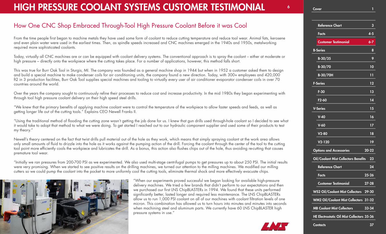
How One CNC Shop Embraced Through-Tool High Pressure Coolant Before it was Cool
From the time people first began to machine metals they have used some form of coolant to reduce cutting temperature and reduce tool wear. Animal fats, kerosene and even plain water were used in the earliest times. Then, as spindle speeds increased and CNC machines emerged in the 1940s and 1950s, metalworking required more sophisticated coolants.
Today, virtually all CNC machines are or can be equipped with coolant delivery systems. The conventional approach is to spray the coolant – either at moderate or high pressure – directly onto the workpiece where the cutting takes place. For a number of applications, however, this method falls short.
This was true for Burr Oak Tool in Sturgis, MI. The company was founded as a general machine shop in 1944 but when in 1952 a customer asked them to design and build a special machine to make condenser coils for air conditioning units, the company found a new direction. Today, with 300+ employees and 420,000 ft2 in 3 production facilities, Burr Oak Tool supplies special machines and tooling to virtually every user of air conditioner evaporator condenser coils in over 70 countries around the world.
Over the years the company sought to continuously refine their processes to reduce cost and increase productivity. In the mid 1980s they began experimenting with through tool high pressure coolant delivery on their high speed steel drills.
“We knew that the primary benefits of applying machine coolant were to control the temperature of the workpiece to allow faster speeds and feeds, as well as getting longer life out of the cutting tools.” Explains CEO Newell Franks II.
“Using the traditional method of flooding the cutting zone wasn’t getting the job done for us. I knew that gun drills used through-hole coolant so I decided to see what it would take to adopt that method to what we were doing. To get started I reached out to our hydraulic component supplier and used some of their products to test my theory.”
Newell’s theory centered on the fact that twist drills pull material out of the hole as they work, which means that simply spraying coolant at the work area allows only small amounts of fluid to drizzle into the hole as it works against the pumping action of the drill. Forcing the coolant through the center of the tool to the cutting tool point more efficiently cools the workpiece and lubricates the drill. As a bonus, this action also flushes chips out of the hole, thus avoiding re-cutting that causes premature tool wear.
“Initially we ran pressures from 200-700 PSI as we experimented. We also used multi-stage centrifugal pumps to get pressures up to about 250 PSI. The initial results were very promising. When we started to see positive results on the drilling machines, we turned our attention to the milling machines. We modified our milling cutters so we could pump the coolant into the pocket to more uniformly cool the cutting tools, eliminate thermal shock and more effectively evacuate chips.
“When our experiments proved successful we began looking for available high-pressure delivery machines. We tried a few brands that didn’t perform to our expectations and then we purchased our first LNS ChipBLASTERs in 1994. We found that these units performed significantly better, lasted longer and required less maintenance. The LNS ChipBLASTERs allow us to run 1,000 PSI coolant on all of our machines with coolant filtration levels of one micron. This combination has allowed us to turn hours into minutes and minutes into seconds when machining steel and aluminum parts. We currently have 60 LNS ChipBLASTER high pressure systems in use.”
HIGH PRESSURE COOLANT SYSTEMS CUSTOMER TESTIMONIAL Cover 1
Reference Chart 3
Facts 4-5
Customer Testimonial 6-7
B-Series 8
B-30/35 9
B-30/70 10
B-30/70H 11
F-Series 12
F-30 13
F2-60 14
V-Series 15
V-40 16
V-60 17
V2-80 18
V2-120 19
Options and Accessories 20-22
Oil/Coolant Mist Collectors Benefits 23
Reference Chart 24
Facts 25-26
Customer Testimonial 27-28
WS2 Oil/Coolant Mist Collectors 29-30
WM2 Oil/Coolant Mist Collectors 31-32
MB Coolant Mist Collectors 33-34
HE Electrostatic Oil Mist Collectors 35-36
Contacts 37
7
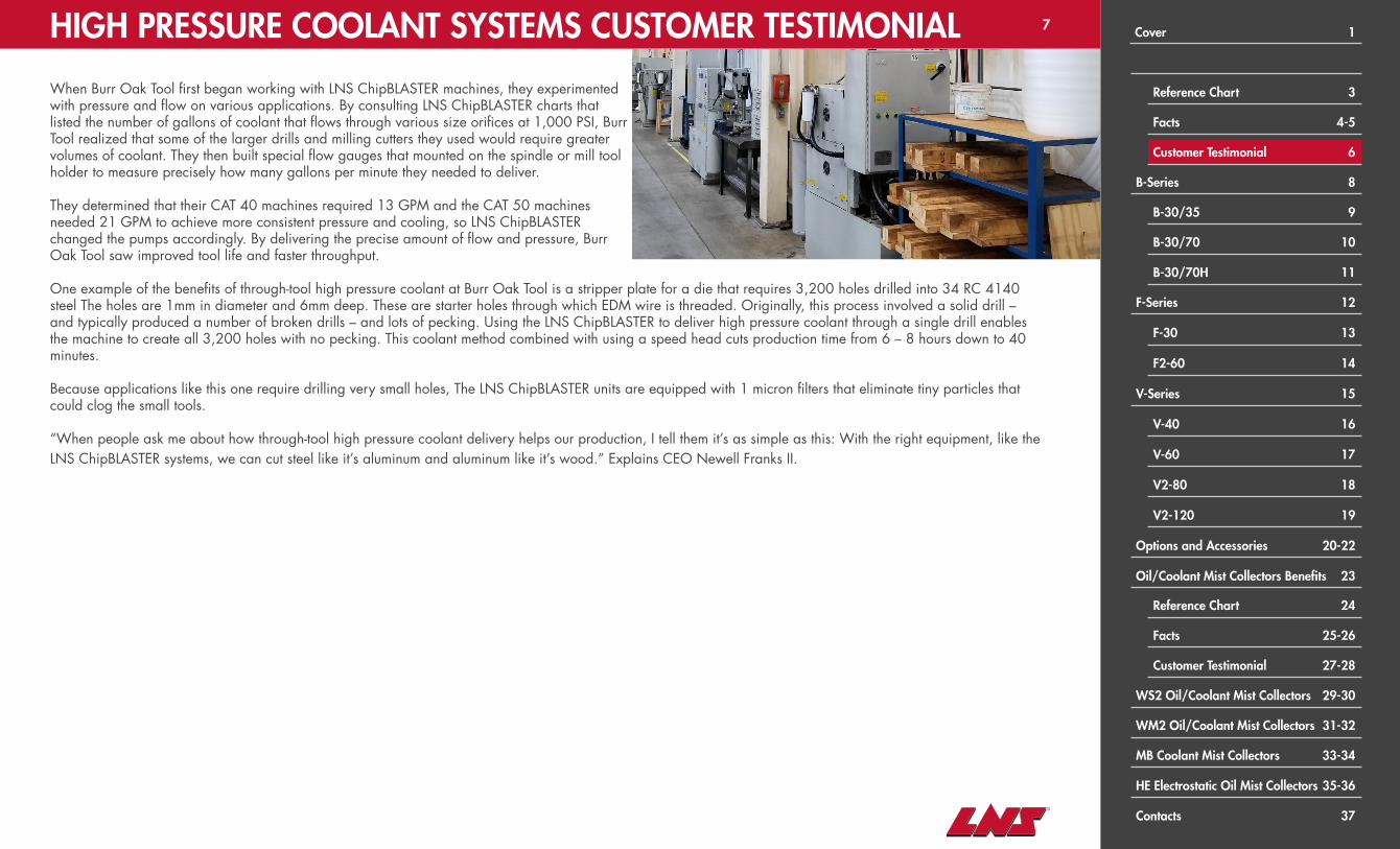
When Burr Oak Tool first began working with LNS ChipBLASTER machines, they experimented with pressure and flow on various applications. By consulting LNS ChipBLASTER charts that listed the number of gallons of coolant that flows through various size orifices at 1,000 PSI, Burr Tool realized that some of the larger drills and milling cutters they used would require greater volumes of coolant. They then built special flow gauges that mounted on the spindle or mill tool holder to measure precisely how many gallons per minute they needed to deliver.
They determined that their CAT 40 machines required 13 GPM and the CAT 50 machines needed 21 GPM to achieve more consistent pressure and cooling, so LNS ChipBLASTER changed the pumps accordingly. By delivering the precise amount of flow and pressure, Burr Oak Tool saw improved tool life and faster throughput.
One example of the benefits of through-tool high pressure coolant at Burr Oak Tool is a stripper plate for a die that requires 3,200 holes drilled into 34 RC 4140 steel The holes are 1mm in diameter and 6mm deep. These are starter holes through which EDM wire is threaded. Originally, this process involved a solid drill – and typically produced a number of broken drills – and lots of pecking. Using the LNS ChipBLASTER to deliver high pressure coolant through a single drill enables the machine to create all 3,200 holes with no pecking. This coolant method combined with using a speed head cuts production time from 6 – 8 hours down to 40 minutes.
Because applications like this one require drilling very small holes, The LNS ChipBLASTER units are equipped with 1 micron filters that eliminate tiny particles that could clog the small tools.
“When people ask me about how through-tool high pressure coolant delivery helps our production, I tell them it’s as simple as this: With the right equipment, like the LNS ChipBLASTER systems, we can cut steel like it’s aluminum and aluminum like it’s wood.” Explains CEO Newell Franks II.
HIGH PRESSURE COOLANT SYSTEMS CUSTOMER TESTIMONIAL Cover 1
Reference Chart 3
Facts 4-5
Customer Testimonial 6
B-Series 8
B-30/35 9
B-30/70 10
B-30/70H 11
F-Series 12
F-30 13
F2-60 14
V-Series 15
V-40 16
V-60 17
V2-80 18
V2-120 19
Options and Accessories 20-22
Oil/Coolant Mist Collectors Benefits 23
Reference Chart 24
Facts 25-26
Customer Testimonial 27-28
WS2 Oil/Coolant Mist Collectors 29-30
WM2 Oil/Coolant Mist Collectors 31-32
MB Coolant Mist Collectors 33-34
HE Electrostatic Oil Mist Collectors 35-36
Contacts 37

8B-SERIES: HIGH PRESSURE COOLANT SYSTEMS
CHIPBLASTER B-SERIESSmall footprint, affordability and easy mobilityCHIPBLASTER B-Series high pressure coolant systems are fixed rate medium and high pressure units. These units are compact and economical with limited options.
B-30/35 B-30/70 B-30/70H
Volumes 30 Liters Per Minute (8 GPM)
Pressures 500 PSI 1000 PSI 1000 PSI
Standard Coolant Tank Capacity N/A N/A 50 Gallons
Cover 1
Reference Chart 3
Facts 4-5
Customer Testimonial 6-7
B-Series 8
B-30/35 9
B-30/70 10
B-30/70H 11
F-Series 12
F-30 13
F2-60 14
V-Series 15
V-40 16
V-60 17
V2-80 18
V2-120 19
Options and Accessories 20-22
Oil/Coolant Mist Collectors Benefits 23
Reference Chart 24
Facts 25-26
Customer Testimonial 27-28
WS2 Oil/Coolant Mist Collectors 29-30
WM2 Oil/Coolant Mist Collectors 31-32
MB Coolant Mist Collectors 33-34
HE Electrostatic Oil Mist Collectors 35-36
Contacts 37

9B-SERIES: HIGH PRESSURE COOLANT SYSTEMS
B-30/35CHIPBLASTER B-30/35 is a single M code controlled, fixed rate medium pressure coolant system. A single pleated, 10-micron filter, automatic overload system, and dirty filter alarm circuit provide a safe machining process that helps prevent damage to the machine-tool, workpiece and tooling. Ideal for machine-tools up to 15 kW (20 hp) and 40 taper mills. The built-in casters make it easy to move for maintenance.
Model Flow Pressure Outlets Tank Options Hydracell Dimensions
B-30/35 8 GPM 500 PSI 1 N/A N/A N/A 34” x 27” X 31”
Cover 1
Reference Chart 3
Facts 4-5
Customer Testimonial 6-7
B-Series 8
B-30/35 9
B-30/70 10
B-30/70H 11
F-Series 12
F-30 13
F2-60 14
V-Series 15
V-40 16
V-60 17
V2-80 18
V2-120 19
Options and Accessories 20-22
Oil/Coolant Mist Collectors Benefits 23
Reference Chart 24
Facts 25-26
Customer Testimonial 27-28
WS2 Oil/Coolant Mist Collectors 29-30
WM2 Oil/Coolant Mist Collectors 31-32
MB Coolant Mist Collectors 33-34
HE Electrostatic Oil Mist Collectors 35-36
Contacts 37

10
CHIPBLASTER B-30/70 is a single M code controlled, fixed rate high pressure coolant system. The unit has 2 pleated, 10-micron filters that can be manually switched as needed, automatic overload system, and dirty filter alarm circuit. These features provide a safe machining process that helps prevent damage to the machine-tool, workpiece and tooling. Ideal for machine-tools up to 15 kW (20 hp) and 40 taper mills. The built-in casters make it easy to move for maintenance.
Model Flow Pressure Outlets Tank Options Hydracell Dimensions
B-30/70 8 GPM 1000 PSI 1 N/A N/A N/A 34” x 27” X 31”
B-SERIES: HIGH PRESSURE COOLANT SYSTEMS
B-30/70
Cover 1
Reference Chart 3
Facts 4-5
Customer Testimonial 6-7
B-Series 8
B-30/35 9
B-30/70 10
B-30/70H 11
F-Series 12
F-30 13
F2-60 14
V-Series 15
V-40 16
V-60 17
V2-80 18
V2-120 19
Options and Accessories 20-22
Oil/Coolant Mist Collectors Benefits 23
Reference Chart 24
Facts 25-26
Customer Testimonial 27-28
WS2 Oil/Coolant Mist Collectors 29-30
WM2 Oil/Coolant Mist Collectors 31-32
MB Coolant Mist Collectors 33-34
HE Electrostatic Oil Mist Collectors 35-36
Contacts 37

11B-SERIES: HIGH PRESSURE COOLANT SYSTEMS
B-30/70HCHIPBLASTER B-30/70H fixed rate, high pressure coolant system has a number of standard safety features, including integrated automatic overload protection, to safeguard the machine-tool, workpiece and tooling during unattended and lights-out production. In addition, maintenance-free cyclonic filtration to 2 microns enables lights-out 24/7 production. The included diaphragm style pump means this unit will stand up to even the most extreme of applications. These safety measures meet or exceed all international requirements. The built-in casters make it easy to move for maintenance.
Model Flow Pressure Outlets Tank Options Hydracell Dimensions
B-30/70H 8 GPM 1000 PSI 1 50 Gallon Oil Skimmer Included 37” x 26” x 49”
Cover 1
Reference Chart 3
Facts 4-5
Customer Testimonial 6-7
B-Series 8
B-30/35 9
B-30/70 10
B-30/70H 11
F-Series 12
F-30 13
F2-60 14
V-Series 15
V-40 16
V-60 17
V2-80 18
V2-120 19
Options and Accessories 20-22
Oil/Coolant Mist Collectors Benefits 23
Reference Chart 24
Facts 25-26
Customer Testimonial 27-28
WS2 Oil/Coolant Mist Collectors 29-30
WM2 Oil/Coolant Mist Collectors 31-32
MB Coolant Mist Collectors 33-34
HE Electrostatic Oil Mist Collectors 35-36
Contacts 37

12F-SERIES: HIGH PRESSURE COOLANT SYSTEMS
CHIPBLASTER F-SERIESModular and FundamentalChipblaster F-Series high pressure coolant systems are fixed rate high pressure units. These units are modular and fundamental with options.
F-30 F2-60
Volumes 30 Liters Per Minute 60 Liters Per Minute
Pressures 1000 PSI
Standard Coolant Tank Capacity 100 Gallons
• The standard F2-60 unit includes two modules.
• Product image shown includes optional ChipCHILLER (third module).
• The standard F-30 unit includes one module.
Cover 1
Reference Chart 3
Facts 4-5
Customer Testimonial 6-7
B-Series 8
B-30/35 9
B-30/70 10
B-30/70H 11
F-Series 12
F-30 13
F2-60 14
V-Series 15
V-40 16
V-60 17
V2-80 18
V2-120 19
Options and Accessories 20-22
Oil/Coolant Mist Collectors Benefits 23
Reference Chart 24
Facts 25-26
Customer Testimonial 27-28
WS2 Oil/Coolant Mist Collectors 29-30
WM2 Oil/Coolant Mist Collectors 31-32
MB Coolant Mist Collectors 33-34
HE Electrostatic Oil Mist Collectors 35-36
Contacts 37
13F-SERIES: HIGH PRESSURE COOLANT SYSTEMS
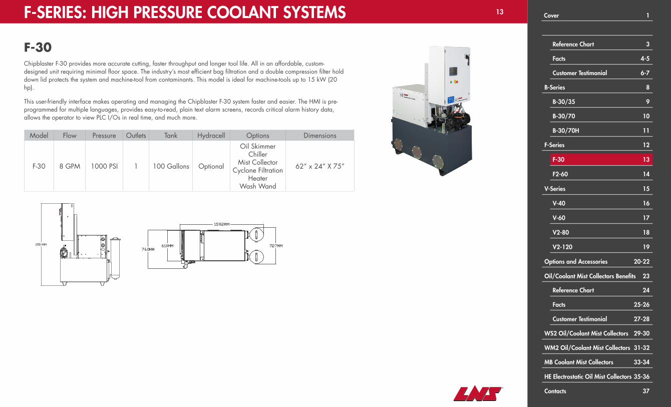
F-30Chipblaster F-30 provides more accurate cutting, faster throughput and longer tool life. All in an affordable, custom-designed unit requiring minimal floor space. The industry’s most efficient bag filtration and a double compression filter hold down lid protects the system and machine-tool from contaminants. This model is ideal for machine-tools up to 15 kW (20 hp).
This user-friendly interface makes operating and managing the Chipblaster F-30 system faster and easier. The HMI is pre-programmed for multiple languages, provides easy-to-read, plain text alarm screens, records critical alarm history data, allows the operator to view PLC I/Os in real time, and much more.
Model Flow Pressure Outlets Tank Hydracell Options Dimensions
F-30 8 GPM 1000 PSI 1 100 Gallons Optional
Oil SkimmerChiller
Mist CollectorCyclone Filtration
HeaterWash Wand
62” x 24” X 75”
Cover 1
Reference Chart 3
Facts 4-5
Customer Testimonial 6-7
B-Series 8
B-30/35 9
B-30/70 10
B-30/70H 11
F-Series 12
F-30 13
F2-60 14
V-Series 15
V-40 16
V-60 17
V2-80 18
V2-120 19
Options and Accessories 20-22
Oil/Coolant Mist Collectors Benefits 23
Reference Chart 24
Facts 25-26
Customer Testimonial 27-28
WS2 Oil/Coolant Mist Collectors 29-30
WM2 Oil/Coolant Mist Collectors 31-32
MB Coolant Mist Collectors 33-34
HE Electrostatic Oil Mist Collectors 35-36
Contacts 37
14F-SERIES: HIGH PRESSURE COOLANT SYSTEMS
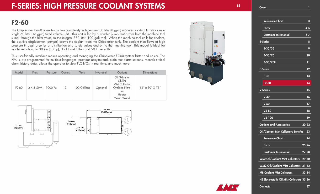
The Chipblaster F2-60 operates as two completely independent 30 liter (8 gpm) modules for dual turrets or as a single 60 liter (16 gpm) fixed volume unit. This unit is fed by a transfer pump that draws from the machine tool sump, through the filter vessel to the integral 380 liter (100 gal) tank. When the machine tool calls for coolant, the positive displacement pump(s) draws the coolant from the Chipblaster tank. The coolant then flows at high pressure through a series of distribution and safety valves and on to the machine tool. This model is ideal for machine-tools up to 30 kw (40 hp), dual turret lathes and 50 taper mills.
This user-friendly interface makes operating and managing the Chipblaster F2-60 system faster and easier. The HMI is pre-programmed for multiple languages, provides easy-to-read, plain text alarm screens, records critical alarm history data, allows the operator to view PLC I/Os in real time, and much more.
Model Flow Pressure Outlets Tank Hydracell Options Dimensions
F2-60 2 X 8 GPM 1000 PSI 2 100 Gallons Optional
Oil SkimmerChiller
Mist CollectorCyclone Filtra-
tionHeater
Wash Wand
62” x 30” X 75”
F2-60
Cover 1
Reference Chart 3
Facts 4-5
Customer Testimonial 6-7
B-Series 8
B-30/35 9
B-30/70 10
B-30/70H 11
F-Series 12
F-30 13
F2-60 14
V-Series 15
V-40 16
V-60 17
V2-80 18
V2-120 19
Options and Accessories 20-22
Oil/Coolant Mist Collectors Benefits 23
Reference Chart 24
Facts 25-26
Customer Testimonial 27-28
WS2 Oil/Coolant Mist Collectors 29-30
WM2 Oil/Coolant Mist Collectors 31-32
MB Coolant Mist Collectors 33-34
HE Electrostatic Oil Mist Collectors 35-36
Contacts 37

15V-SERIES: HIGH PRESSURE COOLANT SYSTEMS
CHIPBLASTER V-SERIESModular Premium ModelsChipblaster V-Series high pressure coolant systems are variable rate high pressure units. These units are premium and modular units with options
V-40 V-60 V2-80 V2-120
Volumes 40 Liters Per Minute 60 Liters Per Minute 80 Liters Per Minute 120 Liters Per Minute
Pressures 1000 PSI
Standard Coolant Tank Capacity 100 Gallons 126 Gallons 100 Gallons 126 Gallons
• V-40 and V-60 standard units include one module, product images shown include Chipblaster Chiller Series (second module)
• V2-80 and V2-120 standard units include two modules, product images shown include Chipblaster Chiller Series (third module)
Cover 1
Reference Chart 3
Facts 4-5
Customer Testimonial 6-7
B-Series 8
B-30/35 9
B-30/70 10
B-30/70H 11
F-Series 12
F-30 13
F2-60 14
V-Series 15
V-40 16
V-60 17
V2-80 18
V2-120 19
Options and Accessories 20-22
Oil/Coolant Mist Collectors Benefits 23
Reference Chart 24
Facts 25-26
Customer Testimonial 27-28
WS2 Oil/Coolant Mist Collectors 29-30
WM2 Oil/Coolant Mist Collectors 31-32
MB Coolant Mist Collectors 33-34
HE Electrostatic Oil Mist Collectors 35-36
Contacts 37

16V-SERIES: HIGH PRESSURE COOLANT SYSTEMS
V-40The Chipblaster V-40 goes well beyond conventional coolant systems to automatically provide optimal pressure and flow for all applications. This assures more accurate cutting, faster throughput and longer tool life. All in an affordable, custom-designed unit requiring minimal floorspace.
Most high-pressure coolant systems concentrate only on chip management and pump at a fixed rate, regardless of need. This wastes energy, especially when using smaller tools, as a majority of the coolant is simply dumped back into the tank. Chipblaster V-40 automatically delivers just the right amount of coolant to maintain optimal pressure and flow for each specific application, thus coolant is never bypassed. The result is energy savings and extended tool life. The Chipblaster 380 liter (100 gallon) standard tank with baffles radiates excess heat to maintain acceptable coolant temperature and reduce foaming.
Model Flow Pressure Outlets Tank Hydracell Options Dimensions
V-40 10 GPM 1000 PSI 1 100 Gallons Optional
Oil SkimmerChiller
Mist CollectorCyclone Filtration
HeaterWash Wand
62” x 24” X 75”
Cover 1
Reference Chart 3
Facts 4-5
Customer Testimonial 6-7
B-Series 8
B-30/35 9
B-30/70 10
B-30/70H 11
F-Series 12
F-30 13
F2-60 14
V-Series 15
V-40 16
V-60 17
V2-80 18
V2-120 19
Options and Accessories 20-22
Oil/Coolant Mist Collectors Benefits 23
Reference Chart 24
Facts 25-26
Customer Testimonial 27-28
WS2 Oil/Coolant Mist Collectors 29-30
WM2 Oil/Coolant Mist Collectors 31-32
MB Coolant Mist Collectors 33-34
HE Electrostatic Oil Mist Collectors 35-36
Contacts 37
17V-SERIES: HIGH PRESSURE COOLANT SYSTEMS
V-60The Chipblaster V-60 is fed by a transfer pump that draws from the machine tool sump, through the filter vessel to the integral 480 liter (126 gal) tank. When the machine tool calls for coolant, the filter pump(s) draw the coolant from the Chipblaster tank and pumps it to the inlet of the positive displacement pump. The coolant then flows at high pressure through a series of distribution and safety valves and on to the machine tool. Ideal for machine tools up to 30kw (40hp), dual turret lathes and 50 taper mills.
This user-friendly interface makes operating and managing the Chipblaster V-60 system faster and easier. The HMI is pre-programmed for multiple languages, provides easy-to-read, plain text alarm screens, records critical alarm history data, allows the operator to view PLC I/Os in real time, and much more.
Model Flow Pressure Outlets Tank Hydracell Options Dimensions
V-60 16 GPM 1000 PSI 1 126 Gallons N/A
Oil SkimmerChiller
Mist CollectorCyclone Filtration
HeaterWash Wand
62” x 33” X 75”
61.9”[1,572 mm]
31”[787 mm]
33”[838 mm]
74.5”[1,892 mm]

Cover 1
Reference Chart 3
Facts 4-5
Customer Testimonial 6-7
B-Series 8
B-30/35 9
B-30/70 10
B-30/70H 11
F-Series 12
F-30 13
F2-60 14
V-Series 15
V-40 16
V-60 17
V2-80 18
V2-120 19
Options and Accessories 20-22
Oil/Coolant Mist Collectors Benefits 23
Reference Chart 24
Facts 25-26
Customer Testimonial 27-28
WS2 Oil/Coolant Mist Collectors 29-30
WM2 Oil/Coolant Mist Collectors 31-32
MB Coolant Mist Collectors 33-34
HE Electrostatic Oil Mist Collectors 35-36
Contacts 37
18
Model Flow Pressure Outlets Tank Hydracell Options Dimensions
V2-80 2 X 10 GPM 1000 PSI 2 100 Gallons Optional
Oil SkimmerChiller
Mist CollectorCyclone Filtration
HeaterWash Wand
62” x 30” X 75”
The Chipblaster V2-80 can operate as two completely independent 40 liter (10 gpm) modules or combine to provide high pressure and very high volumes 80 liters at any time during the same program.
This is the “gold standard” for high pressure coolant systems. It automatically pumps just enough volume to maintain full pressure Other systems pump a fixed rate that is always too much or too little causing foam, heat, and short filter life. Ideal for machine tools up to 40kw (50hp), dual turret lathes and 50 taper mills.
V-SERIES: HIGH PRESSURE COOLANT SYSTEMS
V2-80

19
Model Flow Pressure Outlets Tank Hydracell Options Dimensions
V2-120 2 X 16 GPM 1000 PSI 2 126 Gallons Optional
Oil SkimmerChiller
Mist CollectorCyclone Filtration
HeaterWash Wand
62” x 30” X 75”
The Chipblaster V2-120 can operate as two completely independent 60 liter (16 gpm) modules or combine to provide high pressure and very high volumes 120 liters at any time during the same program. Ideal for machine tools up to 60kw (80hp), dual turret lathes and 50 taper mills.
This user-friendly interface makes operating and managing the Chipblaster V2-120 system faster and easier. The HMI is pre-programmed for multiple languages, provides easy-to-read, plain text alarm screens, records critical alarm history data, allows the operator to view PLC I/Os in real time, and much more.
V-SERIES: HIGH PRESSURE COOLANT SYSTEMS
V2-120
Cover 1
Reference Chart 3
Facts 4-5
Customer Testimonial 6-7
B-Series 8
B-30/35 9
B-30/70 10
B-30/70H 11
F-Series 12
F-30 13
F2-60 14
V-Series 15
V-40 16
V-60 17
V2-80 18
V2-120 19
Options and Accessories 20-22
Oil/Coolant Mist Collectors Benefits 23
Reference Chart 24
Facts 25-26
Customer Testimonial 27-28
WS2 Oil/Coolant Mist Collectors 29-30
WM2 Oil/Coolant Mist Collectors 31-32
MB Coolant Mist Collectors 33-34
HE Electrostatic Oil Mist Collectors 35-36
Contacts 37

20OPTIONS & ACCESSORIES: HIGH PRESSURE COOLANT SYSTEMS
OIL REMOVAL SERIESThe most cost effective and simple method of tramp oil removal is an oil skimmer that mounts on a coolant reservoir and continually draws off tramp oils. Due to the increased agitation, a high-pressure coolant system without recycling capability actually causes coolant to degrade more quickly than normal. An effective coolant system must recycle every drop of coolant by separating the tramp oil and fines from the coolant before it is pumped back into the cutting zone. If the tramp oil is removed, all of the problems mentioned above cease to exist. High quality coolant often stays in good condition for years.
Model Dimension
CB OS Included in base unit footprint
CHILLER SERIES• 34,000 BTU• Cooling capacity suits virtually all applications• Optional heater for precise temperature control
Model Dimensions
CC 34K Included in base unit footprint
CC 34K SA 49” x 34” x 36”
BSeries
FSeries
VSeries
FSeries
VSeries
Cover 1
Reference Chart 3
Facts 4-5
Customer Testimonial 6-7
B-Series 8
B-30/35 9
B-30/70 10
B-30/70H 11
F-Series 12
F-30 13
F2-60 14
V-Series 15
V-40 16
V-60 17
V2-80 18
V2-120 19
Options and Accessories 20-22
Oil/Coolant Mist Collectors Benefits 23
Reference Chart 24
Facts 25-26
Customer Testimonial 27-28
WS2 Oil/Coolant Mist Collectors 29-30
WM2 Oil/Coolant Mist Collectors 31-32
MB Coolant Mist Collectors 33-34
HE Electrostatic Oil Mist Collectors 35-36
Contacts 37

21OPTIONS & ACCESSORIES: HIGH PRESSURE COOLANT SYSTEMS
CYCLONE FILTER SERIES & SLUDGE TANKLNS Chipbalster’s Cyclone filtration system eliminates particulate from coolant by running the fluid through a cyclonic separa-tor. This device creates a vortex to produce centrifugal force that pushes the solids to the Cyclone’s walls and then down to a discharge port. Clean coolant is drawn upwards to an outlet that returns it to the sump.
The FILTER series includes two models – a stand alone unit and one integrated into the high pressure coolant system.
• Up to 100% filtering to 10 microns• Up to 95% filtering to 5 microns• Up to 50% filtering to 2 microns
• Recommended to complement Chipblaster CF-79 cyclone filter. The Chipblaster sludge tank holds particulates outside of the machine-tool sump and is easy to access for cleaning.
Model Dimension
CF-79 Included in base unit footprint
CF-79 SA 27” x 25” x 38”
Model Dimension
CB ST 200 37” X 18” X 26”
FSeries
VSeries
LNS Chipblaster’s sludge tank is designed to trap particulate and keep it out of the machine tool sump. Particulate slurry is dis-charged from the cyclone to the sludge tank. It take 10-12 minutes for the particulate slurry to follow the flow path through the specially designed baffles. This increased flow path reduces the velocity of the fluid and allows particulate to settle to the bottom of the tank. Clean water is discharged back to the machine tool sump via the overflow. When the tank gets full of sludge, simply remove the lid and the three baffles and shovel out the sludge.
Cover 1
Reference Chart 3
Facts 4-5
Customer Testimonial 6-7
B-Series 8
B-30/35 9
B-30/70 10
B-30/70H 11
F-Series 12
F-30 13
F2-60 14
V-Series 15
V-40 16
V-60 17
V2-80 18
V2-120 19
Options and Accessories 20-22
Oil/Coolant Mist Collectors Benefits 23
Reference Chart 24
Facts 25-26
Customer Testimonial 27-28
WS2 Oil/Coolant Mist Collectors 29-30
WM2 Oil/Coolant Mist Collectors 31-32
MB Coolant Mist Collectors 33-34
HE Electrostatic Oil Mist Collectors 35-36
Contacts 37

22OPTIONS & ACCESSORIES: HIGH PRESSURE COOLANT SYSTEMS
FP FILTER SERIESThe FP Series of filter vessels from LNS provides an economically priced bag style filtration solution. Single filter vessels can be used in line with your existing pump or complete filter and pump packages are available for use in sump polishing applications. A wide range of bag filters are available in various micron ratings to enable you to fine tune your application.
Filter Bag Sizes Available:• 1 Micron• 5 Micron• 10 Micron• 15 Micron• 25 Micron• 50 Micron• 100 Micron
FP-4 Model ShownAvailable Configurations:FP-1: Single filter vessel on tripod stand
FP-2: Dual filter vessels on floor stand
FP-2 w/pump: Dual filter vessels on floor stand with transfer pump and dirty filter alarm
FP-4: Quad filter vessels on floor stand
FP-4 w/pump: Quad filter vessels on floor stand with transfer pump and dirty filter alarm
Designed for applications not exceeding 15 psi and 20 gpm
Cover 1
Reference Chart 3
Facts 4-5
Customer Testimonial 6-7
B-Series 8
B-30/35 9
B-30/70 10
B-30/70H 11
F-Series 12
F-30 13
F2-60 14
V-Series 15
V-40 16
V-60 17
V2-80 18
V2-120 19
Options and Accessories 20-22
Oil/Coolant Mist Collectors Benefits 23
Reference Chart 24
Facts 25-26
Customer Testimonial 27-28
WS2 Oil/Coolant Mist Collectors 29-30
WM2 Oil/Coolant Mist Collectors 31-32
MB Coolant Mist Collectors 33-34
HE Electrostatic Oil Mist Collectors 35-36
Contacts 37

23OIL/COOLANT MIST COLLECTORS BENEFITS
Air Filtration Systems Benefits
Eliminating oil or coolant mist, aerosols, and smoke typical in CNC wet machining does away with residue build up on machine components, thus decreasing downtime and maintenance to substantially increase the life of CNC machines.
Further, oil/coolant mist collectors safeguard the health of employees, reduce absenteeism and protect costly machined parts by removing airborne contaminants and the smoke produced by oil and coolant exposed to high temperatures during CNC machining processes.
Cover 1
Reference Chart 3
Facts 4-5
Customer Testimonial 6-7
B-Series 8
B-30/35 9
B-30/70 10
B-30/70H 11
F-Series 12
F-30 13
F2-60 14
V-Series 15
V-40 16
V-60 17
V2-80 18
V2-120 19
Options and Accessories 20-22
Oil/Coolant Mist Collectors Benefits 23
Reference Chart 24
Facts 25-26
Customer Testimonial 27-28
WS2 Oil/Coolant Mist Collectors 29-30
WM2 Oil/Coolant Mist Collectors 31-32
MB Coolant Mist Collectors 33-34
HE Electrostatic Oil Mist Collectors 35-36
Contacts 37

24OIL/COOLANT MIST COLLECTORS REFERENCE CHART
Model Chipblaster MB 300 Chipblaster MB 700 Chipblaster MB 1200
For machines up to 2.27 m3 (80 ft3) up to 3.4 m3 (120 ft3) over 3.4 m3 (120 ft3)
Airflow (cfm) 300 700 1200
Motor (hp) 0.5 1 3
Amps at 230V 2.1 3.2 7.5
Weight (lb) 65 80 140
Sound Level (dB(A)) 71 73 74
Suction Inlet Diameter (in) 6 6 6
EMU
LSIO
NEM
ULS
ION
or
OIL
INSTALLATION OPTIONS:• LNS Chipblaster high pressure coolant system
mount• Machine mounted with adjustable legs• Vertical stand• Cart on wheels• LNS Turbo chip conveyor mount
INSTALLATION OPTIONS:• Machine mount• Vertical stand• Cart on wheels• LNS Turbo chip conveyor mount• LNS Chipblaster high pressure coolant system
mount*FOX WS 2 330, 700, 1020, 1250: with HEPA filter installed, airflow is about 10% less
• All units painted in RAL 7035/7016 (special colors available upon request)
• Electrical motors meet current efficiency standards EISA 2007 / IE2 and available as either: (V/Hz) 208/60, 230/60, 400/60, 460/60 (special voltages / frequencies available upon request)
Model Fox WS2170
Fox WS2330
Fox WS2700
Fox WS21020
Fox WS2 1250
Airflow* (cfm) 168 330 665 1012 1248
Motor (hp) 0.4 0.6 1.2 2.4 3.5
Amps at 230V 1.5 2 2.9 5.7 8.3
Weight (lb) 62 77 121 165 187
Sound Level (dB(A)) 63 65 71 73 75
Suction Inlet Diameter 100mm (4”) 123mm (5”) 150mm (6”) 200mm (8”) 200mm (8”)
FOX WS2 OIL / COOLANT MIST COLLECTORS
CHIPBLASTER MB COOLANT MIST COLLECTORSO
IL
Model Airflow* (cfm) Motor (hp) Amps at 220V Weight (lb) Sound Level (dB(A)) Suction Inlet Diameter
Fox HE 1000 882 0.5 2.3 117 67 150mm (6”)
FOX HE 1000 OIL MIST COLLECTORS
Model Airflow* (cfm) Motor (hp) Amps at 230V Weight (lb) Sound Level (dB(A)) Suction Inlet Diameter
Fox WM2 2500 2350 4.8 10.6 551 79 250mm (10”)
FOX WM2 OIL / COOLANT MIST COLLECTORS
Cover 1
Reference Chart 3
Facts 4-5
Customer Testimonial 6-7
B-Series 8
B-30/35 9
B-30/70 10
B-30/70H 11
F-Series 12
F-30 13
F2-60 14
V-Series 15
V-40 16
V-60 17
V2-80 18
V2-120 19
Options and Accessories 20-22
Oil/Coolant Mist Collectors Benefits 23
Reference Chart 24
Facts 25-26
Customer Testimonial 27-28
WS2 Oil/Coolant Mist Collectors 29-30
WM2 Oil/Coolant Mist Collectors 31-32
MB Coolant Mist Collectors 33-34
HE Electrostatic Oil Mist Collectors 35-36
Contacts 37

25
Choosing Oil/Coolant Mist Collectors To Best Suit Your CNC Applications
Among the reasons young people give for not choosing a career in manufacturing is the perception that factories are dirty, unhealthy places to work. In truth the majority of today’s CNC machine shop owners take pride in providing a clean, safe workplace for their employees and make significant investments in health and safety related equipment. One of the most challenging issues is oil mist and smoke created by the oil-based, synthetic or emulsion type coolants used by modern CNC machine tools.
Three technologies from a single sourceToday’s CNC machine shop owners take pride in providing a clean, safe workplace for their employees by investing in manufacturing equipment designed to protect their health and safety. One of the most challenging issues they face is mist and smoke created by the oil-based, synthetic or emulsion type coolants used in modern CNC machining. If left unabated, this mist hangs in the air and eventually settles on all surfaces including machines, walls, floors and people.
Breathing these vapors can cause serious respiratory problems, aggravate existing breathing conditions, and irritating the eyes, nose, throat and skin, leading to employee health problems and absenteeism. Slick, oil-covered floors present the risk of injuries from falls. All of which creates potential liabilities for the shop owners and problems with OSHA.
Even high-efficiency factory HVAC systems typically can’t keep the workplace free of these contaminants, which is why many shops invest in oil/coolant mist collectors. It’s important to note that not all oil/coolant mist collectors work the same way. The technologies behind the three most common types of oil/coolant mist collectors are: multi-stage, electrostatic and centrifugal. Each has unique characteristics that make it the best choice for specific CNC machining applications.
Multi-Stage Media Oil/Coolant Mist CollectorsLNS Fox WS2 oil/coolant mist collectors use a three-stage system that consists of an initial pre-filtration cartridge, a cyclonic separation chamber and a final stage filter. This results in achieving 99% filtration and residual oil mist concentration of only 0.2 mg/m3(milligrams per cubic meter). This level of efficiency is guaranteed to be consistent throughout the oil mist collector’s life. LNS oil/coolant mist collectors accommodate all machine types and processes using water-soluble, synthetic or neat oil coolants. The unique multi-stage design virtually eliminates noise and vibration. Furthermore, reduces energy consumption and provides verifiable, continuous filtration efficiency.
Filtration StagesAs oil mist is drawn into the collector, it passes through the proprietary, multi-layered pre-filtration cartridge. This cartridge consists of three filtering layers that remove solid particulates and entrain bulk liquids. At the same time, it agglomerates finer mist particles into larger ones. Overall efficiency at this stage is 92%.
In the second stage, oil mist droplets accumulated in stage one reduce further by means of inertial impaction. Whereas small dust particles and liquid droplets impact a deflecting surface, in this case a special impeller that creates a cyclonic effect. The particles are forced to a cylinder wall where they coalesce and are then captured.
The third stage uses a proprietary high surface area cartridge media filter to remove any remaining oil mist. This filter removes 99% of oil mist to exceed OSHA and NIOSH standards. Users can also add an optional 4th stage HEPA filter that removes 99.97% of cutting oil smoke particles.
Efficient MonitoringAn integrated pressure gauge monitors the condition of the stage three filter by measuring airflow. Routine maintenance consists of replacing the long-life filters that typically maintain efficiency for 3,000 – 4,000 hours. Average time to replace a filter is five minutes.
Because many shops have a wide variety of machine tools, LNS can match any CNC machine with appropriate oil / coolant mist collectors. The WS2 Series has five models with 170 to 1250 CFM airflow rates. The WM Series are for larger or multiple machines with 2350 CFM airflow rates.
OIL/COOLANT MIST COLLECTORS FACTS Cover 1
Reference Chart 3
Facts 4-5
Customer Testimonial 6-7
B-Series 8
B-30/35 9
B-30/70 10
B-30/70H 11
F-Series 12
F-30 13
F2-60 14
V-Series 15
V-40 16
V-60 17
V2-80 18
V2-120 19
Options and Accessories 20-22
Oil/Coolant Mist Collectors Benefits 23
Reference Chart 24
Facts 25-26
Customer Testimonial 27-28
WS2 Oil/Coolant Mist Collectors 29-30
WM2 Oil/Coolant Mist Collectors 31-32
MB Coolant Mist Collectors 33-34
HE Electrostatic Oil Mist Collectors 35-36
Contacts 37

26OIL/COOLANT MIST COLLECTORS FACTS
Electrostatic Oil Mist CollectorsRecent innovations by LNS take the electrostatic technology to the next level with the LNS Fox HE 1000. A 4-stage system that eliminates 98.3% of mist, smoke and odors from wet machining operations using straight oil. The first stage is a coarse metallic mesh pre-filter that traps tiny chips. In stage 2, a fine mesh pre-filter coalesces particulates. Stage 3 electrostatically ionizes and collects oil mist. In stage 4 a fine mesh post-filter completes the process before releasing clean air that exceeds OSHA and NIOSH guidelines for industrial air quality. The variable speed motor provides fine turning of the airflow to suit your application and maximize maintenance intervals. An optional, 100% recyclable HEPA fine filter further eliminates dry smoke.
Although all oil mist collectors require some maintenance, keeping the LNS Fox HE electrostatic system performing at peak efficiency requires as little as two filter cleanings a year, depending on the application. Save time by accessing different elements of the unit from one centralized location with the innovative dual door design. The wireless one-piece ionizer and collector cell is designed and manufactured by LNS for safe, quick, and easy maintenance.
Centrifugal Coolant Mist CollectorsDesigned for water-based applications, LNS ChipBLASTER MB Series mist collectors apply centrifugal force to thrust coolant particulates to the outside of the housing. Coolant flows along the housing surface to exit through a specially designed port. As liquid drains from the collector, air flows through washable aluminum filters and clean air exceeding OSHA air quality standards is returned to the shop.
The permanent aluminum filters are easily removed for cleaning, on average, about once each year. A built-in pressure gauge lets you know when the filters need cleaning, and 3 mounting options insure the best fit for every application. To precisely match each CNC machine and its applications, there are 3 LNS ChipBLASTER MB models with 300, 700 and 1200 CFM airflow.
Cover 1
Reference Chart 3
Facts 4-5
Customer Testimonial 6-7
B-Series 8
B-30/35 9
B-30/70 10
B-30/70H 11
F-Series 12
F-30 13
F2-60 14
V-Series 15
V-40 16
V-60 17
V2-80 18
V2-120 19
Options and Accessories 20-22
Oil/Coolant Mist Collectors Benefits 23
Reference Chart 24
Facts 25-26
Customer Testimonial 27-28
WS2 Oil/Coolant Mist Collectors 29-30
WM2 Oil/Coolant Mist Collectors 31-32
MB Coolant Mist Collectors 33-34
HE Electrostatic Oil Mist Collectors 35-36
Contacts 37
27
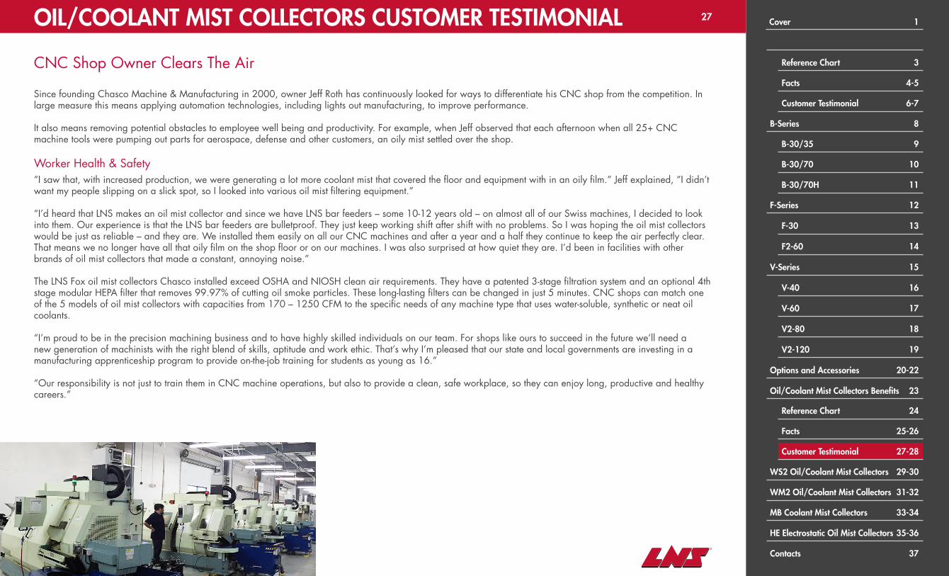
CNC Shop Owner Clears The Air
Since founding Chasco Machine & Manufacturing in 2000, owner Jeff Roth has continuously looked for ways to differentiate his CNC shop from the competition. In large measure this means applying automation technologies, including lights out manufacturing, to improve performance.
It also means removing potential obstacles to employee well being and productivity. For example, when Jeff observed that each afternoon when all 25+ CNC machine tools were pumping out parts for aerospace, defense and other customers, an oily mist settled over the shop.
Worker Health & Safety“I saw that, with increased production, we were generating a lot more coolant mist that covered the floor and equipment with in an oily film.” Jeff explained, “I didn’t want my people slipping on a slick spot, so I looked into various oil mist filtering equipment.”
“I’d heard that LNS makes an oil mist collector and since we have LNS bar feeders – some 10-12 years old – on almost all of our Swiss machines, I decided to look into them. Our experience is that the LNS bar feeders are bulletproof. They just keep working shift after shift with no problems. So I was hoping the oil mist collectors would be just as reliable – and they are. We installed them easily on all our CNC machines and after a year and a half they continue to keep the air perfectly clear. That means we no longer have all that oily film on the shop floor or on our machines. I was also surprised at how quiet they are. I’d been in facilities with other brands of oil mist collectors that made a constant, annoying noise.”
The LNS Fox oil mist collectors Chasco installed exceed OSHA and NIOSH clean air requirements. They have a patented 3-stage filtration system and an optional 4th stage modular HEPA filter that removes 99.97% of cutting oil smoke particles. These long-lasting filters can be changed in just 5 minutes. CNC shops can match one of the 5 models of oil mist collectors with capacities from 170 – 1250 CFM to the specific needs of any machine type that uses water-soluble, synthetic or neat oil coolants.
“I’m proud to be in the precision machining business and to have highly skilled individuals on our team. For shops like ours to succeed in the future we’ll need a new generation of machinists with the right blend of skills, aptitude and work ethic. That’s why I’m pleased that our state and local governments are investing in a manufacturing apprenticeship program to provide on-the-job training for students as young as 16.”
“Our responsibility is not just to train them in CNC machine operations, but also to provide a clean, safe workplace, so they can enjoy long, productive and healthy careers.”
OIL/COOLANT MIST COLLECTORS CUSTOMER TESTIMONIAL Cover 1
Reference Chart 3
Facts 4-5
Customer Testimonial 6-7
B-Series 8
B-30/35 9
B-30/70 10
B-30/70H 11
F-Series 12
F-30 13
F2-60 14
V-Series 15
V-40 16
V-60 17
V2-80 18
V2-120 19
Options and Accessories 20-22
Oil/Coolant Mist Collectors Benefits 23
Reference Chart 24
Facts 25-26
Customer Testimonial 27-28
WS2 Oil/Coolant Mist Collectors 29-30
WM2 Oil/Coolant Mist Collectors 31-32
MB Coolant Mist Collectors 33-34
HE Electrostatic Oil Mist Collectors 35-36
Contacts 37

28
How a Precision CNC Shop Keeps its New Facility Free from Oil/Coolant Mist and Particulates
When you move your CNC shop into a new building, you want to keep it as clean, healthy and safe for your employees as possible. That’s why Enviro-Tech Industries decided to install LNS FOX Oil/Coolant Mist Collectors throughout its new 44,000 square foot facility in Boise Idaho.
The precision machining company employs 30+ VMCs, HMCs, lathes and 5-axis machining centers, specializing in producing tight tolerance parts for demanding customers in aerospace, medical products and many other industries. Established in 1993, Enviro-Tech moved into its current facility 4 years ago. Recognizing that many of their machining centers are used in applications that create large amounts of coolant mist and particulates that could pose health and safety risks, the company investigated the best way to control air quality in the new shop.
According to Facilities Manager Attila Sipiczki, the mist collectors used in the previous plant were not performing to Enviro-Tech standards, allowing deposits to form on the walls, floors and equipment. After investigating various options for the new facility, the company experimented with a few used LNS Oil/Coolant Mist Collectors obtained from another shop. The results were promising, so they worked with LNS to determine which additional units would best serve their needs.
Mr. Sipiczki adds, “The people from LNS were knowledgeable and helped us select the right Mist Collector for each of our CNC machines. I also liked that they have a number of different mounting accessories so you can tailor the installation to each machine tool.”
“We were familiar with LNS because we also have some of their bar feeders and chip conveyors in the shop. We knew from experience that they make reliable products and have responsive service and support. They performed air quality tests when the new equipment was installed, and we have cleaner air, cleaner machines and our workers are happier with the conditions in our facility.”
The LNS FOX WS 2 Series of oil/Mist Collectors includes 5 models with air flow rates from 170 to 1250 CFM. The WM Series, for larger or multiple machines, have airflow of 2350 CFM. All systems exceed OSHA and NIOSH standards and remove 99% of oil mist. An optional HEPA filter removes 99.7% of cutting smoke particulates.
OIL/COOLANT MIST COLLECTORS CUSTOMER TESTIMONIAL Cover 1
Reference Chart 3
Facts 4-5
Customer Testimonial 6-7
B-Series 8
B-30/35 9
B-30/70 10
B-30/70H 11
F-Series 12
F-30 13
F2-60 14
V-Series 15
V-40 16
V-60 17
V2-80 18
V2-120 19
Options and Accessories 20-22
Oil/Coolant Mist Collectors Benefits 23
Reference Chart 24
Facts 25-26
Customer Testimonial 27-28
WS2 Oil/Coolant Mist Collectors 29-30
WM2 Oil/Coolant Mist Collectors 31-32
MB Coolant Mist Collectors 33-34
HE Electrostatic Oil Mist Collectors 35-36
Contacts 37
29
EMU
LSIO
N o
r O
IL
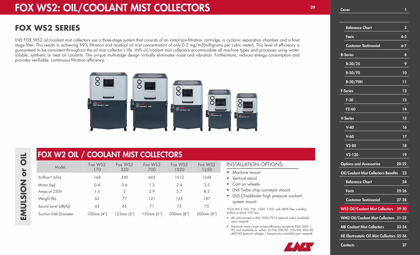
INSTALLATION OPTIONS:• Machine mount• Vertical stand• Cart on wheels• LNS Turbo chip conveyor mount• LNS Chipblaster high pressure coolant
system mount
*FOX WS 2 330, 700, 1020, 1250: with HEPA filter installed, airflow is about 10% less
• All units painted in RAL 7035/7016 (special colors available upon request)
• Electrical motors meet current efficiency standards EISA 2007 / IE2 and available as either: (V/Hz) 208/60, 230/60, 400/60, 460/60 (special voltages / frequencies available upon request)
Model Fox WS2170
Fox WS2330
Fox WS2700
Fox WS21020
Fox WS21250
Airflow* (cfm) 168 330 665 1012 1248
Motor (hp) 0.4 0.6 1.2 2.4 3.5
Amps at 230V 1.5 2 2.9 5.7 8.3
Weight (lb) 62 77 121 165 187
Sound Level (dB(A)) 63 65 71 73 75
Suction Inlet Diameter 100mm (4”) 123mm (5”) 150mm (6”) 200mm (8”) 200mm (8”)
FOX W2 OIL / COOLANT MIST COLLECTORS
FOX WS2: OIL/COOLANT MIST COLLECTORS
FOX WS2 SERIESLNS FOX WS2 oil/coolant mist collectors use a three-stage system that consists of an initial pre-filtration cartridge, a cyclonic separation chamber and a final stage filter. This results in achieving 99% filtration and residual oil mist concentration of only 0.2 mg/m3(milligrams per cubic meter). This level of efficiency is guaranteed to be consistent throughout the oil mist collector’s life. LNS oil/coolant mist collectors accommodate all machine types and processes using water-soluble, synthetic or neat oil coolants. The unique multi-stage design virtually eliminates noise and vibration. Furthermore, reduces energy consumption and provides verifiable, continuous filtration efficiency.
Cover 1
Reference Chart 3
Facts 4-5
Customer Testimonial 6-7
B-Series 8
B-30/35 9
B-30/70 10
B-30/70H 11
F-Series 12
F-30 13
F2-60 14
V-Series 15
V-40 16
V-60 17
V2-80 18
V2-120 19
Options and Accessories 20-22
Oil/Coolant Mist Collectors Benefits 23
Reference Chart 24
Facts 25-26
Customer Testimonial 27-28
WS2 Oil/Coolant Mist Collectors 29-30
WM2 Oil/Coolant Mist Collectors 31-32
MB Coolant Mist Collectors 33-34
HE Electrostatic Oil Mist Collectors 35-36
Contacts 37

30FOX WS2: OIL/COOLANT MIST COLLECTORS
FOX WS2 SERIES
Keeping Your Production Running CleanAs mist, aerosols, and smoke filter through the filtration stages, excess liquid will be guided to the V-shape mist collector floor bottom. The V-shape floor promotes efficient drainage and accumulated liquid does not come in contact with the pre-filter, providing extended pre-filter life. A drain spout is located on the back of the unit to facilitate effective drainage of liquid pooled into the V-shape floor.
Drain Spout
V-Shape Floor
Performance MonitoringTo maximize each filter’s life, the WS 2 is designed with two air pressure gauges to provide ease of maintenance. The bottom gauge measures the air pressure at the pre-filter, and the top gauge measures it at the final filter. The gauges clearly show each filter’s clogging or pressure difference, so it is simple to determine when to replace each filter. These indicators simplify filter maintenance, so that the unit can run at optimum continuous efficiency. It is recommended that the internal filters* be replaced once per year or every 4,000 hours* of mist collector operation.* Process and application specific
Installation EaseThe suction inlet port is versatile – it can be placed on the left or right side depending on the machine configuration or space allowance. Determining the suction inlet placement can be determined on-site during installation. Units are designed with tall feet for hardware clearance, thereby providing speed and ease of installation.
Suction inlet port
left or right side
Tall feet
Dimensions (Inches)Unit A B C D E F G H I L N1 X N2 X M
FOX WS2 170 14.88 18.78 22.95 16.73 9.53 3.90 0.98 2.68 16.54 4.02 13.07 x 15.04 x 0.35
FOX WS2 330 16.06 20.28 25.67 18.11 10.87 4.88 0.98 2.64 17.72 4.72 14.30 x 15.55 x 0.35
FOX WS2 700 20.67 23.62 31.54 21.38 14.25 5.87 0.98 2.36 22.32 5.31 18.82 x 18.82 x 0.35
FOX WS2 1020 23.62 26.50 35.75 24.29 15.59 7.80 0.98 2.32 25.20 6.93 21.73 x 21.73 x 0.35
FOX WS2 1250 26.10 29.02 39.13 26.77 17.20 7.80 0.98 2.32 27.68 7.13 24.21 x 24.21 x 0.35
Cover 1
Reference Chart 3
Facts 4-5
Customer Testimonial 6-7
B-Series 8
B-30/35 9
B-30/70 10
B-30/70H 11
F-Series 12
F-30 13
F2-60 14
V-Series 15
V-40 16
V-60 17
V2-80 18
V2-120 19
Options and Accessories 20-22
Oil/Coolant Mist Collectors Benefits 23
Reference Chart 24
Facts 25-26
Customer Testimonial 27-28
WS2 Oil/Coolant Mist Collectors 29-30
WM2 Oil/Coolant Mist Collectors 31-32
MB Coolant Mist Collectors 33-34
HE Electrostatic Oil Mist Collectors 35-36
Contacts 37

31
EMU
LSIO
N o
r O
IL
FOX WM2: OIL/COOLANT MIST COLLECTORS
FOX WM2 SERIESThe Fox WM2 series represents the ideal solution for the filtration of oil mist for large machining centers, connecting multiple machine tools or for when large air flow rates are required.
Designed with the same level of high quality engineering and reliability of the smaller Fox WS 2 series, the WM2 unit can completely eliminate mist, aerosol and smoke typical of wet machining processes exceeding OSHA and NIOSH guidelines for mist concentration for industrial air quality. Fox WM2 unit is modular in its flow rate and available in 2500, 5000 and 7500 CFM versions.
FOX WM2 OIL / COOLANT MIST COLLECTORSModel Airflow* (cfm) Motor (hp) Amps at 230V Weight (lb) Sound Level (dB(A)) Suction Inlet Diameter
Fox WM2 2500 2350 4.8 10.6 551 79 250mm (10”)
Models available :• Fox WM2 2500• Fox WM2 5000 (two WM 2500’s in tandem)• Fox WM2 7500 (three WM 2500’s in tandem)
Cover 1
Reference Chart 3
Facts 4-5
Customer Testimonial 6-7
B-Series 8
B-30/35 9
B-30/70 10
B-30/70H 11
F-Series 12
F-30 13
F2-60 14
V-Series 15
V-40 16
V-60 17
V2-80 18
V2-120 19
Options and Accessories 20-22
Oil/Coolant Mist Collectors Benefits 23
Reference Chart 24
Facts 25-26
Customer Testimonial 27-28
WS2 Oil/Coolant Mist Collectors 29-30
WM2 Oil/Coolant Mist Collectors 31-32
MB Coolant Mist Collectors 33-34
HE Electrostatic Oil Mist Collectors 35-36
Contacts 37

32FOX WM2: OIL/COOLANT MIST COLLECTORS
FOX WM2 SERIES
Easy MaintenanceMaintenance requires less than ten minutes (complete replacement of filters). The result is a considerable saving in time and costs across the life of the unit. Additionally, guaranteed reliability is due to the special impeller and to the high quality of the components, each thoroughly selected and tested. Average filtration life is 4,000 operating hours* with water-soluble coolants. Units are mechanically guaranteed for three (3) years.*Process and application specific
Installation Ease The suction inlet port is versatile – it can be placed on the left, right or rear depending on the machine configuration or space allowance. Suction inlet placement can be determined on-site during installation.
Reversible Hinged Door with Metal Door KeyFlexibility to have the door open from the left or right depending on your installation needs for easy access to the filters.
DrainageSloped drainage tank with integrated P-trap
33.6"
17.9
"
31.4"
81.3
"Performance Monitoring with Digital Pressure SwitchesTo maximize each filter’s life, the WM2 is designed with digital air pressure switches to provide ease of maintenance. Indicator lights clearly show each filter’s clogging or pressure difference, so it is simple to determine when to replace each filter. These indicators simplify filter maintenance, so that the unit can run at optimum continuous efficiency. It is recommended that the internal filters be replaced once per year or every 4,000 hours* of mist collector operation.*Process and application specific
Guaranteed Filtration – Principle of Operation : Three (3) Stages1st Stage – COALESCINGMulti-layered Metallic FiltrationWashable metallic mesh that allows the removal of chips and larger particles of oil to coalesce for efficient draining.
2nd Stage – PRE-FILTRATIONProprietary Multi-layered FiltrationSpecial media with progressive filtration levels that allow the removal of large particles of oil but provides slow and efficient draining effect.
3rd Stage – MAIN FILTRATIONProprietary High Surface Area FiltrationExtended filtration area, made of a multi-media arrangement with a filtration level above 99% (measured according to AFNOR NFX44-060) removing the finer particle sizes.
4th Stage - Absolute Filtration (Optional):Absolute filter HEPA H13 with efficiency equivalent to 99.95% MPPS according to EN 1822 which completely eliminates aerosols and dry smoke or other particles.
33.6"
17.9
"
31.4"
81.3
"
Cover 1
Reference Chart 3
Facts 4-5
Customer Testimonial 6-7
B-Series 8
B-30/35 9
B-30/70 10
B-30/70H 11
F-Series 12
F-30 13
F2-60 14
V-Series 15
V-40 16
V-60 17
V2-80 18
V2-120 19
Options and Accessories 20-22
Oil/Coolant Mist Collectors Benefits 23
Reference Chart 24
Facts 25-26
Customer Testimonial 27-28
WS2 Oil/Coolant Mist Collectors 29-30
WM2 Oil/Coolant Mist Collectors 31-32
MB Coolant Mist Collectors 33-34
HE Electrostatic Oil Mist Collectors 35-36
Contacts 37

33
Model ChipblasterMB 300
ChipblasterMB 700
ChipblasterMB 1200
For machines up to 2.27 m3 (80 ft3) up to 3.4 m3 (120 ft3) over 3.4 m3 (120 ft3)
Airflow (cfm) 300 700 1200
Motor (hp) 0.5 1 3
Amps at 230V 2.1 3.2 7.5
Weight (lb) 65 80 140
Sound Level (dB(A)) 71 73 74
Suction Inlet Diameter (in) 6 6 6
EMU
LSIO
N
INSTALLATION OPTIONS:• LNS Chipblaster high pressure coolant
system mount• Machine mounted with adjustable legs• Vertical stand• Cart on wheels• LNS Turbo chip conveyor mount
CHIPBLASTER MB COOLANT MIST COLLECTORS
CHIPBLASTER MB: COOLANT MIST COLLECTORS
CHIPBLASTER MB SERIESLNS ChipBLASTER MB Series mist collectors apply centrifugal force to thrust coolant particulates to the outside of the housing. Coolant flows along the housing surface to exit through a specially designed port. As liquid drains from the collector, air flows through washable aluminum filters and clean air exceeding OSHA air quality standards is returned to the shop. An additional filtration level is available. The extended filtration area is made of multi-media arrangement to remove remaining mist and provide the guaranteed removal, an average efficiency above 99% (measured according to AFNOR NFX 44-060 standard).
Cover 1
Reference Chart 3
Facts 4-5
Customer Testimonial 6-7
B-Series 8
B-30/35 9
B-30/70 10
B-30/70H 11
F-Series 12
F-30 13
F2-60 14
V-Series 15
V-40 16
V-60 17
V2-80 18
V2-120 19
Options and Accessories 20-22
Oil/Coolant Mist Collectors Benefits 23
Reference Chart 24
Facts 25-26
Customer Testimonial 27-28
WS2 Oil/Coolant Mist Collectors 29-30
WM2 Oil/Coolant Mist Collectors 31-32
MB Coolant Mist Collectors 33-34
HE Electrostatic Oil Mist Collectors 35-36
Contacts 37
34CHIPBLASTER MB: COOLANT MIST COLLECTORS
CHIPBLASTER MB SERIES
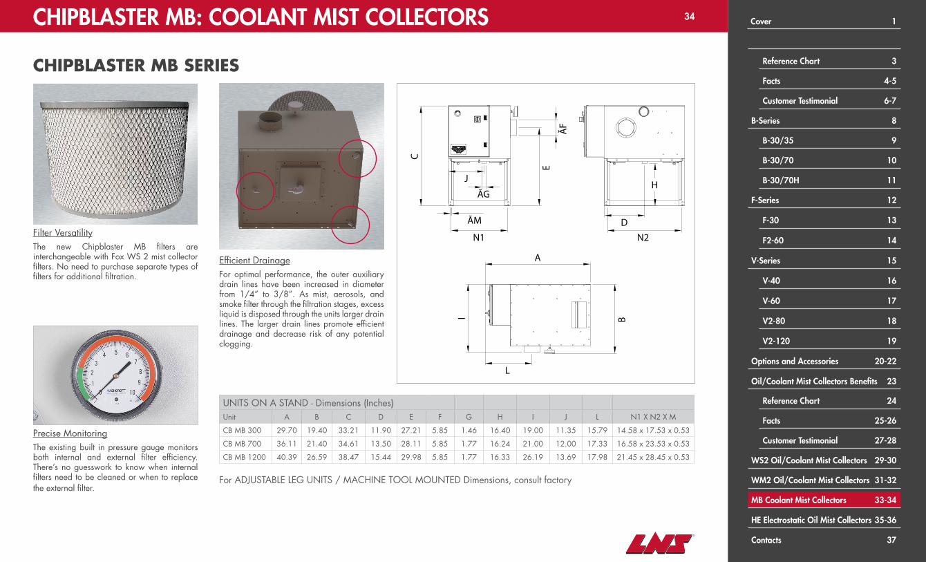
Precise MonitoringThe existing built in pressure gauge monitors both internal and external filter efficiency. There’s no guesswork to know when internal filters need to be cleaned or when to replace the external filter.
Efficient DrainageFor optimal performance, the outer auxiliary drain lines have been increased in diameter from 1/4” to 3/8”. As mist, aerosols, and smoke filter through the filtration stages, excess liquid is disposed through the units larger drain lines. The larger drain lines promote efficient drainage and decrease risk of any potential clogging.
Filter VersatilityThe new Chipblaster MB filters are interchangeable with Fox WS 2 mist collector filters. No need to purchase separate types of filters for additional filtration.
UNITS ON A STAND - Dimensions (Inches)Unit A B C D E F G H I J L N1 X N2 X M
CB MB 300 29.70 19.40 33.21 11.90 27.21 5.85 1.46 16.40 19.00 11.35 15.79 14.58 x 17.53 x 0.53
CB MB 700 36.11 21.40 34.61 13.50 28.11 5.85 1.77 16.24 21.00 12.00 17.33 16.58 x 23.53 x 0.53
CB MB 1200 40.39 26.59 38.47 15.44 29.98 5.85 1.77 16.33 26.19 13.69 17.98 21.45 x 28.45 x 0.53
A
C
ĂF
E
N1
ĂM
N2
L
BID
HĂG
J
A
C
ĂF
E
N1
ĂM
N2
L
BID
HĂG
J
A
C
ĂF
E
N1
ĂM
N2
L
BI
D
HĂG
J
For ADJUSTABLE LEG UNITS / MACHINE TOOL MOUNTED Dimensions, consult factory
Cover 1
Reference Chart 3
Facts 4-5
Customer Testimonial 6-7
B-Series 8
B-30/35 9
B-30/70 10
B-30/70H 11
F-Series 12
F-30 13
F2-60 14
V-Series 15
V-40 16
V-60 17
V2-80 18
V2-120 19
Options and Accessories 20-22
Oil/Coolant Mist Collectors Benefits 23
Reference Chart 24
Facts 25-26
Customer Testimonial 27-28
WS2 Oil/Coolant Mist Collectors 29-30
WM2 Oil/Coolant Mist Collectors 31-32
MB Coolant Mist Collectors 33-34
HE Electrostatic Oil Mist Collectors 35-36
Contacts 37

35FOX HE: OIL MIST COLLECTORS
FOX HE SERIESThe LNS Fox HE series electrostatic oil mist collector is specifically designed for machine tools to eliminate mist, smoke and odors from wet machining operations using straight oil. It is characterized by a sophisticated design, compact dimensions, with standard and customizable accessories. The standard configuration provides a high level of air filtration exceeding OSHA and NIOSH guidelines for industrial air quality. The wireless one-piece ionizer and collector cell is designed and manufactured by LNS for safe, quick, and easy maintenance.
OIL
Model Airflow* (cfm) Motor (hp) Amps at 220V Weight (lb) Sound Level (dB(A)) Suction Inlet Diameter
Fox HE 1000 882 0.5 2.3 117 67 15mm (6”)
FOX HE 1000 OIL MIST COLLECTORS
Cover 1
Reference Chart 3
Facts 4-5
Customer Testimonial 6-7
B-Series 8
B-30/35 9
B-30/70 10
B-30/70H 11
F-Series 12
F-30 13
F2-60 14
V-Series 15
V-40 16
V-60 17
V2-80 18
V2-120 19
Options and Accessories 20-22
Oil/Coolant Mist Collectors Benefits 23
Reference Chart 24
Facts 25-26
Customer Testimonial 27-28
WS2 Oil/Coolant Mist Collectors 29-30
WM2 Oil/Coolant Mist Collectors 31-32
MB Coolant Mist Collectors 33-34
HE Electrostatic Oil Mist Collectors 35-36
Contacts 37

36FOX HE: OIL MIST COLLECTORS
FOX HE SERIES
Maintenance EfficiencyThe variable speed motor provides fine turning of the airflow to suit your application and maximize maintenance intervals.
Dual Door AccessSave time by accessing different elements of the Fox HE 1000 from one centralized location. The dual door innovation serves two purposes and can be opened from the side or the bottom of the unit. Electrical components are easily accessed by opening the door from the side and filters are accessed with the same door by opening it from the bottom up. The door is affixed to the unit with gas shocks to minimize wear and tear.
Filtration EfficiencyHigh filtration efficiency reduces the amount of oil mist in the workplace environment. The one piece, light weight electrostatic cell is designed and manufactured by LNS providing filtration levels of 98.3% and above. Any filtration system requires maintenance. With the Fox HE 1000 design, little time is spent keeping the unit at peak performance. Cleaning of the pre-filters and post-filter metallic mesh takes only minutes and is recommended a few times a year depending on your application. For OPTIONAL HEPA KIT and OPTIONAL
DISCHARGE, consult factory
Dimensions (inches)
Unit A B C D ØF ØG H I ØM N1 N2 N3 N4 P1 P2
HE 1000 17.09 21.44 22.08 18.50 5.91 0.75 3.78 28.23 0.35 24.49 16.46 12.20 7.95 15.59 9.84
Q
ØF
P1
ØM ØG
N1
I
CA
H
N4
N3N2
B
P2
D
Cover 1
Reference Chart 3
Facts 4-5
Customer Testimonial 6-7
B-Series 8
B-30/35 9
B-30/70 10
B-30/70H 11
F-Series 12
F-30 13
F2-60 14
V-Series 15
V-40 16
V-60 17
V2-80 18
V2-120 19
Options and Accessories 20-22
Oil/Coolant Mist Collectors Benefits 23
Reference Chart 24
Facts 25-26
Customer Testimonial 27-28
WS2 Oil/Coolant Mist Collectors 29-30
WM2 Oil/Coolant Mist Collectors 31-32
MB Coolant Mist Collectors 33-34
HE Electrostatic Oil Mist Collectors 35-36
Contacts 37

37LNS CONTACTS
LNS NORTH AMERICA REGIONAL SALES MANAGERS
KentuckyOhioPennsylvaniaWest VirginiaTennessee
MIDEAST EASTBob Bodde513-309-4407
MissouriIllinoisIndiana
MIDWEST CENTRALJohn Stone513-460-4295
ConnecticutDelawareEastern CanadaMaineMarylandMassachusetts
New HampshireNew JerseyNew YorkRhode IslandVermont
NORTHEASTBrian Hand513-313-2551
IowaKansasMinnesotaNebraskaNorth Dakota
OklahomaSouth DakotaTexas
MIDWEST WESTBart Sheffield612-889-2800
ArizonaSouthern CaliforniaNevadaNew Mexico
WEST COAST SOUTHRobert Oldhafer562-230-5080
AlabamaArkansasFloridaGeorgiaLouisiana
MississippiNorth CarolinaPuerto RicoSouth CarolinaVirginia
SOUTHEASTJosh Hudson513-575-6903
MEXICOFernando Serrano+52 1 (722) 155-8977
LNS America, Inc.4621 East Tech DriveCincinnati, Ohio 45245
Phone:513-528-5674
Bar Feeds (BF)Mist Collectors (MC)Steady Rests (SR)General Sales [email protected]@[email protected]
Customer Service (Service)[email protected]@[email protected]
Customer Service (Parts)[email protected]@[email protected]
Northern CaliforniaIdahoMontanaWyomingColorado
OregonWashingtonUtahWestern Canada
WEST COAST NORTHJames Riddle310-502-4184
MichiganWisconsin
MIDWEST NORTHChad Kernats513-547-0296
LNS Turbo203 Turbo DriveKings Mountain, NC 28086
Phone:704-739-7111
Chip Conveyors (CC)General Sales [email protected]
Customer Service (Service)[email protected]
Customer Service (Parts)[email protected]
LNS ChipBLASTER13605 S Mosiertown RoadMeadville, PA 16335
Phone:814-724-6278
High Pressure (HP) Coolant SystemsGeneral Sales [email protected]
Customer Service (Service)[email protected]
Customer Service (Parts)[email protected]
Cover 1
Reference Chart 3
Facts 4-5
Customer Testimonial 6-7
B-Series 8
B-30/35 9
B-30/70 10
B-30/70H 11
F-Series 12
F-30 13
F2-60 14
V-Series 15
V-40 16
V-60 17
V2-80 18
V2-120 19
Options and Accessories 20-22
Oil/Coolant Mist Collectors Benefits 23
Reference Chart 24
Facts 25-26
Customer Testimonial 27-28
WS2 Oil/Coolant Mist Collectors 29-30
WM2 Oil/Coolant Mist Collectors 31-32
MB Coolant Mist Collectors 33-34
HE Electrostatic Oil Mist Collectors 35-36
Contacts 37

PERIPHERAL VISIONFor CNC machine tool peripherals, it’s LNS, then all the rest
www.LNS-northamerica.com
Cover 1
Reference Chart 3
Facts 4-5
Customer Testimonial 6-7
B-Series 8
B-30/35 9
B-30/70 10
B-30/70H 11
F-Series 12
F-30 13
F2-60 14
V-Series 15
V-40 16
V-60 17
V2-80 18
V2-120 19
Options and Accessories 20-22
Oil/Coolant Mist Collectors Benefits 23
Reference Chart 24
Facts 25-26
Customer Testimonial 27-28
WS2 Oil/Coolant Mist Collectors 29-30
WM2 Oil/Coolant Mist Collectors 31-32
MB Coolant Mist Collectors 33-34
HE Electrostatic Oil Mist Collectors 35-36
Contacts 37