Embed Size (px)
Citation preview

IP FABRIC EVPN-VXLAN REFERENCE ARCHITECTURE
Reference Architecture
©2019, Juniper Networks, Inc.

2©2019, Juniper Networks, Inc.
IP Fabric EVPN-VXLAN Reference Architecture
TABLE OF CONTENTSThe IP Fabric EVPN-VXLAN Solution Overview ..................................................................3
Solution Components ................................................................................................................3IP Fabric Underlay Network .......................................................................................................................................3
Network Virtualization Overlay ................................................................................................................................4
Overlay Services ........................................................................................................................4Bridged Overlay............................................................................................................................................................4
Centrally Routed Overlay (aka Spine Routed) ........................................................................................................5
Edge Routed Overlay (aka Leaf Routed) ..................................................................................................................6
Overlay Design and Deployment Choices .............................................................................6
Border Devices ............................................................................................................................7
Multihoming ................................................................................................................................8Multihoming Support for Ethernet-Connected Systems ......................................................................................8
Service Insertion ........................................................................................................................8
Data Center Interconnect .........................................................................................................9Layer 2 DCI ...................................................................................................................................................................9
Layer 3 DCI ................................................................................................................................................................ 10
Multicast-Enabled EVPN-Based Data Center ....................................................................11Multicast in Overlay—Intra Subnet Multicast Forwarding ................................................................................ 11
Multicast in Overlay—Inter-Subnet Multicast Forwarding ............................................................................... 11
Multicast in a Centrally Routed Overlay Architecture ...................................................................................... 12
Automating the Data Center EVPN-VXLAN Fabrics .........................................................13Automating EVPN-VXLAN Fabric by Ansible/Saltstack ................................................................................... 13
Contrail Enterprise Multicloud ..............................................................................................13Multicloud .................................................................................................................................................................. 13
Telemetry/Analytics .................................................................................................................14AppFormix .................................................................................................................................................................. 14
Conclusion .................................................................................................................................16
About Juniper Networks .........................................................................................................16

3©2019, Juniper Networks, Inc.
IP Fabric EVPN-VXLAN Reference Architecture
The IP Fabric EVPN-VXLAN Solution OverviewTraditionally, data centers have used Layer 2 technologies such as Spanning Tree Protocol (STP) and multichassis link aggregation group (MC-LAG) to connect compute and storage resources. As these data centers evolve to scale out multitenant networks, a new data center architecture is needed that decouples the underlay (physical) network from a tenant overlay network.
Using a Layer 3 IP-based underlay coupled with an EVPN-VXLAN overlay, data centers, enterprises, and cloud operators can deploy much larger networks than otherwise possible using traditional L2 Ethernet-based architectures. With overlays, endpoints—such as servers or virtual machines (VMs)—can be placed anywhere in the network and remain connected to the same logical L2 network, decoupling the virtual topology from the physical topology.
Solution ComponentsIP Fabric Underlay NetworkIn data center environments, the role of the physical underlay network is to provide an IP fabric. Also known as a Clos network, it is the IP fabric’s responsibility to provide unicast IP connectivity from any physical device (server, storage device, router, or switch) to any other physical device. An ideal underlay network provides low-latency, nonblocking, high-bandwidth connectivity from any point in the network to any other point in the network.
IP fabrics can vary in size and scale. A typical solution uses two layers—spine and leaf—to form what is known as a three-stage IP fabric, where each leaf device is connected to each spine device, as shown in Figure 1.
Spine Spine Spine Spine
Leaf Leaf Leaf Leaf Leaf
Figure 1: The three-stage IP fabric
INTRODUCTION This reference architecture describes Juniper Networks Ethernet VPN (EVPN)-Virtual Extensible LAN (VXLAN) solutions, which simplify and automate many of the tasks associated with managing a data center and extending its connectivity into other data centers or public cloud offerings.
The document provides a functional description of the solution itself while also characterizing the components that comprise the solution.
It is assumed the reader has IP networking knowledge and a basic understanding of data center technologies.

4©2019, Juniper Networks, Inc.
IP Fabric EVPN-VXLAN Reference Architecture
As the scale of the fabric increases, it becomes necessary to expand to a five-stage IP fabric, as shown in Figure 2. This scenario adds a fabric layer (or “super spine”) to provide inter-pod, or inter-data center, connectivity.
Spine Spine Spine Spine
LeafLeaf Leaf Leaf Leaf Leaf
Fabric Fabric Fabric Fabric
Figure 2: The five-stage IP fabric
A key benefit of an IP-based fabric is natural resiliency. High availability mechanisms such as MC-LAG or Juniper’s Virtual Chassis technology are not required, as the IP fabric uses multiple links at each layer and device. Resiliency and redundancy are provided by the physical network infrastructure itself.
The reference architecture described in this document uses EBGP as the routing protocol in the underlay network for its dependability and scalability. Each spine and leaf device is assigned its own autonomous system, with a unique 32-bit autonomous system number to support EBGP. While other routing protocols such as OSPF/IS-IS can be used in the data center underlay network, they are beyond the scope of this document.
Network Virtualization OverlayA network virtualization overlay is a virtual network that is transported over an IP underlay—a functional building block that enables multitenancy within a network and allows you to share a single physical network across multiple tenants while isolating each tenant’s network traffic from other tenants.
A tenant is a user community (such as a business unit, department, workgroup, or application) that contains groups of endpoints. These groups may communicate with other groups in the same tenancy, and tenants may communicate with other tenants if permitted by network policies. A group is typically expressed as a subnet (VLAN) that can communicate with other devices in the same subnet and reach external groups and endpoints via a virtual routing and forwarding (VRF) instance.
Overlay Services IBGP is a routing protocol that exchanges reachability information across an IP network. When combined with Multiprotocol IBGP (MP-IBGP), IBGP allows EVPN to exchange reachability information with VXLAN virtual tunnel endpoint (VTEP) devices. This is required to establish inter-VTEP VXLAN tunnels and use them for overlay connectivity services.
The following sections discuss various overlay service models as part of the EVPN-VXLAN reference architecture.
Bridged OverlayIn a bridged overlay model (see Figure 4), Ethernet VLANs are extended between leaf devices across VXLAN tunnels. These leaf-to-leaf VXLAN tunnels support data center networks that require Ethernet connectivity between leaf devices but do not need routing between the VLANs. As a result, spine devices only provide basic underlay and overlay connectivity for the leaf devices and do not perform routing or gateway services seen with other overlay methods. Juniper Networks® MX Series 5G Universal Routing Platforms or SRX Series Services Gateways external to the EVPN/VXLAN fabric can be used to perform the necessary routing.

5©2019, Juniper Networks, Inc.
IP Fabric EVPN-VXLAN Reference Architecture
Leaf devices establish VTEPs in order to connect to other leaf devices. The tunnels enable the leaf devices to send VLAN traffic to other leaf devices and Ethernet-connected end systems in the data center. The simplicity of this overlay service makes it attractive for operators who need an easy way to introduce EVPN/VXLAN into their existing Ethernet-based data center network.
Blue VLAN Green VLAN Blue VLANGreen VLAN
Ethernet-ConnectedEnd System
BlueVLAN
GreenVLAN
Figure 3: Bridged overlay
Centrally Routed Overlay (aka Spine Routed)The nature of a centrally routed bridging overlay is that routing occurs at a central gateway within the data center network (the spine layer, in this example) rather than at the VTEP device where end systems are connected (the leaf layer, in this example). You can use this overlay model when routed traffic needs to pass through a centralized gateway or when edge VTEP devices lack the required routing capabilities. As shown in Figure 4, traffic that originates at the Ethernet-connected end systems is forwarded to the leaf VTEP devices over a trunk (multiple VLANs) or an access port (single VLAN). The VTEP device forwards the traffic to local end systems or to an end system at a remote VTEP device. An integrated routing and bridging (IRB) interface at each spine device routes traffic between the Ethernet virtual networks.
Blue VLAN Green VLAN
L2 VXLAN
Ethernet-ConnectedEnd System
L3 VXLAN GW
BlueVLAN
GreenVLAN
Figure 4: Centrally routed overlay

6©2019, Juniper Networks, Inc.
IP Fabric EVPN-VXLAN Reference Architecture
Edge Routed Overlay (aka Leaf Routed)In this Ethernet service model, the IRB interfaces are moved to leaf device VTEPs at the edge of the overlay network to bring IP routing closer to the end systems. Due to the special ASIC capabilities required to support bridging, routing, and EVPN/VXLAN in one device, edge routed bridging overlays are only possible on certain switches, such as the high-performance, versatile Juniper Networks QFX10000 line of Switches.
This option enables faster server-to-server, intra-data center traffic (also known as east-west traffic), where the communicating end systems are connected to the same leaf device VTEP. As a result, routing occurs much closer to the end systems than with centrally routed bridging overlays. It also allows for a simpler overall network.
With this model, spine devices are configured to handle IP traffic only, removing the need to extend bridging overlays to the spine devices.
Blue VLAN Green VLAN
L2 VXLAN
Ethernet-ConnectedEnd System
Lean Spine
BlueVLAN
GreenVLAN
Figure 5: Edge routed overlay
Overlay Design and Deployment ChoicesOperators have multiple ways to design their overlay services. Table 1 shows central vs. edge routed deployment considerations.
Table 1: Centrally vs. Edge Routed Considerations
When to Centrally Route When to Edge Route
When most traffic is north-south (typically in the campus) When most traffic is east-west and heavily segmented within the pod
When centralized tenant IP/VRF management is preferred When scale is high and state needs to be distributed to reduce convergence time on failures
When leaf devices do not support VXLAN routing When configuration complexity is abstracted by controller

7©2019, Juniper Networks, Inc.
IP Fabric EVPN-VXLAN Reference Architecture
Border DevicesBorder devices connect to external devices (such as a WAN or outside a fabric) or to services, including (but not limited to) firewalls, load balancers, Domain Name System (DNS), Dynamic Host Configuration Protocol (DHCP), and others. Border devices can be on a leaf (Figure 6) or spine (Figure 7), completely independent of gateway positioning on leaf or spine devices.
Blue VLAN Green VLAN
L2 VXLANBorder Leaf
Devices
Lean Spine
Services (SRX/DNS/DHCP)or WAN
Figure 6: Border leaf device
Blue VLAN Green VLAN
BorderSpine Devices
WAN or AnythingExternal to Fabric
Figure 7: Border spine device
8©2019, Juniper Networks, Inc.
IP Fabric EVPN-VXLAN Reference Architecture
MultihomingMultihoming Support for Ethernet-Connected SystemsThe Ethernet-connected multihoming technology enables Ethernet traffic to be load-balanced across the fabric between VTEPs on different leaf devices connected to the same end system.
Leaf Leaf Leaf
ESi
Ethernet-ConnectedEnd System
To SpineDevices
Figure 8: Ethernet-connected end system multihoming
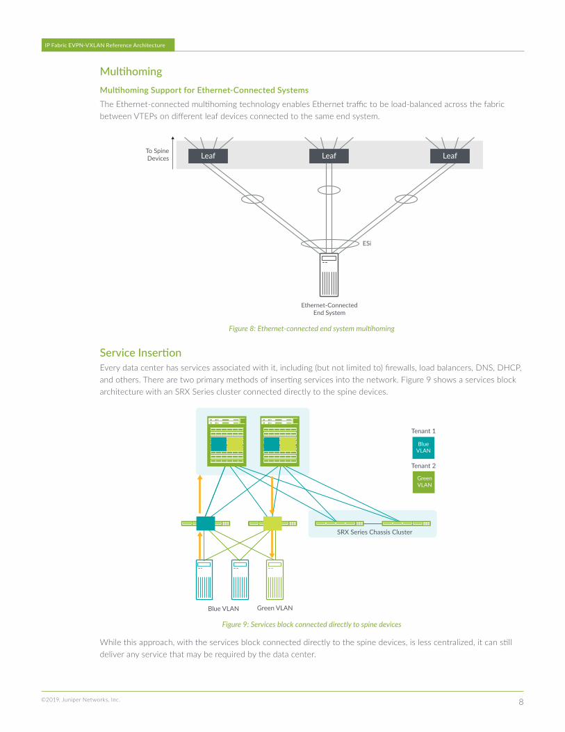
Service Insertion Every data center has services associated with it, including (but not limited to) firewalls, load balancers, DNS, DHCP, and others. There are two primary methods of inserting services into the network. Figure 9 shows a services block architecture with an SRX Series cluster connected directly to the spine devices.
Blue VLAN Green VLAN
Tenant 1
Tenant 2
BlueVLAN
GreenVLAN
SRX Series Chassis Cluster
Figure 9: Services block connected directly to spine devices
While this approach, with the services block connected directly to the spine devices, is less centralized, it can still deliver any service that may be required by the data center.
9©2019, Juniper Networks, Inc.
IP Fabric EVPN-VXLAN Reference Architecture
This deployment model is typically employed in the following use cases:
• Operators who don’t mind if their spine devices serve multiple roles
• Operators who use a distributed model where services may exist at different points in the data center
• Data centers where spine device ports can be spared for connecting to services devices
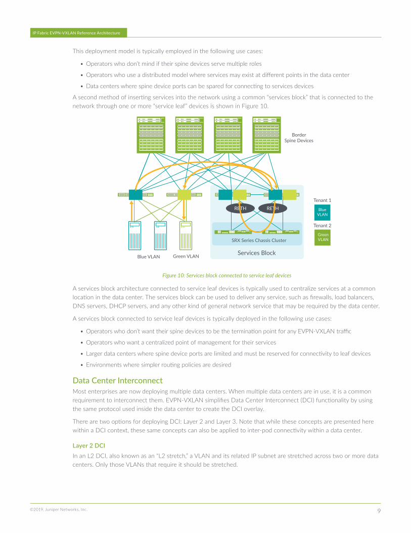
A second method of inserting services into the network using a common “services block” that is connected to the network through one or more “service leaf” devices is shown in Figure 10.
Blue VLAN Green VLAN
BorderSpine Devices
Tenant 1
Tenant 2
Services Block
RETH RETH BlueVLAN
GreenVLANSRX Series Chassis Cluster
Figure 10: Services block connected to service leaf devices
A services block architecture connected to service leaf devices is typically used to centralize services at a common location in the data center. The services block can be used to deliver any service, such as firewalls, load balancers, DNS servers, DHCP servers, and any other kind of general network service that may be required by the data center.
A services block connected to service leaf devices is typically deployed in the following use cases:
• Operators who don’t want their spine devices to be the termination point for any EVPN-VXLAN traffic
• Operators who want a centralized point of management for their services
• Larger data centers where spine device ports are limited and must be reserved for connectivity to leaf devices
• Environments where simpler routing policies are desired
Data Center InterconnectMost enterprises are now deploying multiple data centers. When multiple data centers are in use, it is a common requirement to interconnect them. EVPN-VXLAN simplifies Data Center Interconnect (DCI) functionality by using the same protocol used inside the data center to create the DCI overlay.
There are two options for deploying DCI: Layer 2 and Layer 3. Note that while these concepts are presented here within a DCI context, these same concepts can also be applied to inter-pod connectivity within a data center.
Layer 2 DCIIn an L2 DCI, also known as an “L2 stretch,” a VLAN and its related IP subnet are stretched across two or more data centers. Only those VLANs that require it should be stretched.

10©2019, Juniper Networks, Inc.
IP Fabric EVPN-VXLAN Reference Architecture
Layer 3 DCIL3 DCI is achieved in an EVPN-VXLAN environment using the EVPN Type 5 route. The subnet must only exist within a single data center; otherwise it becomes an L2 DCI connection and, as explained above, only those VLANs that require it should be stretched. EVPN Type-5 routes are the recommended method of achieving L3 DCI.
Figure 11 shows a DCI reference model with border spine devices and Figure 12 shows the same, with DCI traffic exiting via service leaf devices.
Blue VLAN Green VLAN Services Block
RETH1/ESI
DC1 DC2
RETH2/ESI
Blue VLAN Red VLAN
EVPN Type 5
EVPN Type 2/L2 Stretch
Services Block
RETH1/ESI
RETH2/ESI
DCI Options:1. IP Backbone2. MPLS Backbone
SRX Series Chassis Cluster SRX Series Chassis Cluster
Figure 11: A DCI reference architecture with border spine devices
Blue VLAN Green VLAN Services Block
RETH1/ESI
DC1 DC2
RETH2/ESI
Blue VLAN Red VLAN
EVPN Type 5
EVPN Type 2/L2 Stretch
Services Block
RETH1/ESI
RETH2/ESI
DCI Options:1. IP Backbone2. MPLS Backbone
SRX Series Chassis Cluster SRX Series Chassis Cluster
Figure 12: A DCI reference architecture with border leaf devices

11©2019, Juniper Networks, Inc.
IP Fabric EVPN-VXLAN Reference Architecture
Multicast-Enabled EVPN-Based Data Center Multicast in an EVPN environment is relatively simple, as the broadcast, unknown unicast, and multicast (BUM) traffic inside the EVPN-VXLAN fabric is replicated to all other VTEPs belonging to the same virtual network identifier (VNI) (also known as ingress replication or head-end replication). This is a simpler solution for smaller deployments as there is no need for any multicast protocols in the underlay network. However, for larger deployments with multicast-enabled infrastructure, ingress replication alone can lead to scalability and performance issues. Multicast optimization in an overlay environment is critical to address these limitations, which are inherent to ingress replication.
Multicast in Overlay—Intra Subnet Multicast ForwardingAs seen in Figure 13, in networks with selective multicast (SMET/EVPN Type 6) optimization, replication is not sent to Leaf 3 with no active receiver. In the absence of SMET optimization, the same ingress leaf device would have assumed the burden of replicating multiple copies and all leaf devices would have received the multicast traffic, wasting fabric bandwidth. Also, with the spine configured as an assisted replicator (AR), the ingress Leaf 1 will delegate the replication job to the VNI-aware spine.
With AR
Leaf 1 Leaf 2 Leaf 3
R1R2R2
R1
With SMET
Traffic will NOT be replicatedto server if leaf supports IGMPsnooping and IGMP Join synce
(EVPN Type 7/8)
Figure 13: Intra-subnet overlay multicast forwarding
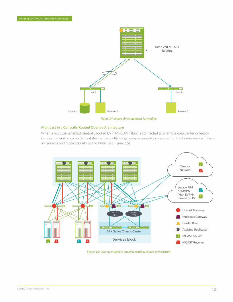
Multicast in Overlay—Inter-Subnet Multicast ForwardingRegardless of whether it is centrally routed or edge routed, inter-VNI multicast routing is done at the spine. In Figure 14, both Leaf 1 and Leaf 2 have receivers and multiple copies are sent by the spine, resulting in hair pinning for local receivers (Receiver 1).
12©2019, Juniper Networks, Inc.
IP Fabric EVPN-VXLAN Reference Architecture
Leaf 1 Leaf 2
Receiver 2Receiver 1Source 1
Inter-VNI MCASTRouting
Figure 14: Inter-subnet multicast forwarding
Multicast in a Centrally Routed Overlay Architecture When a multicast-enabled, centrally routed EVPN-VXLAN fabric is connected to a remote data center or legacy campus network via a border leaf device, the multicast gateway is generally collocated on the border device if there are sources and receivers outside the fabric (see Figure 15).
SRX Series Chassis Cluster
Services Block
RETH1/ESI
RETH2/ESI
Campus Network
Unicast Gateway
Multicast Gateway
Border Role
Assisted Replicator
MCAST Source
MCAST Receiver
Legacy PIMor MVPN(Non EVPN)baseed on DC
S
S
S
R
R
RR RS
Figure 15: Overlay multicast-enabled centrally routed architecture
13©2019, Juniper Networks, Inc.
IP Fabric EVPN-VXLAN Reference Architecture
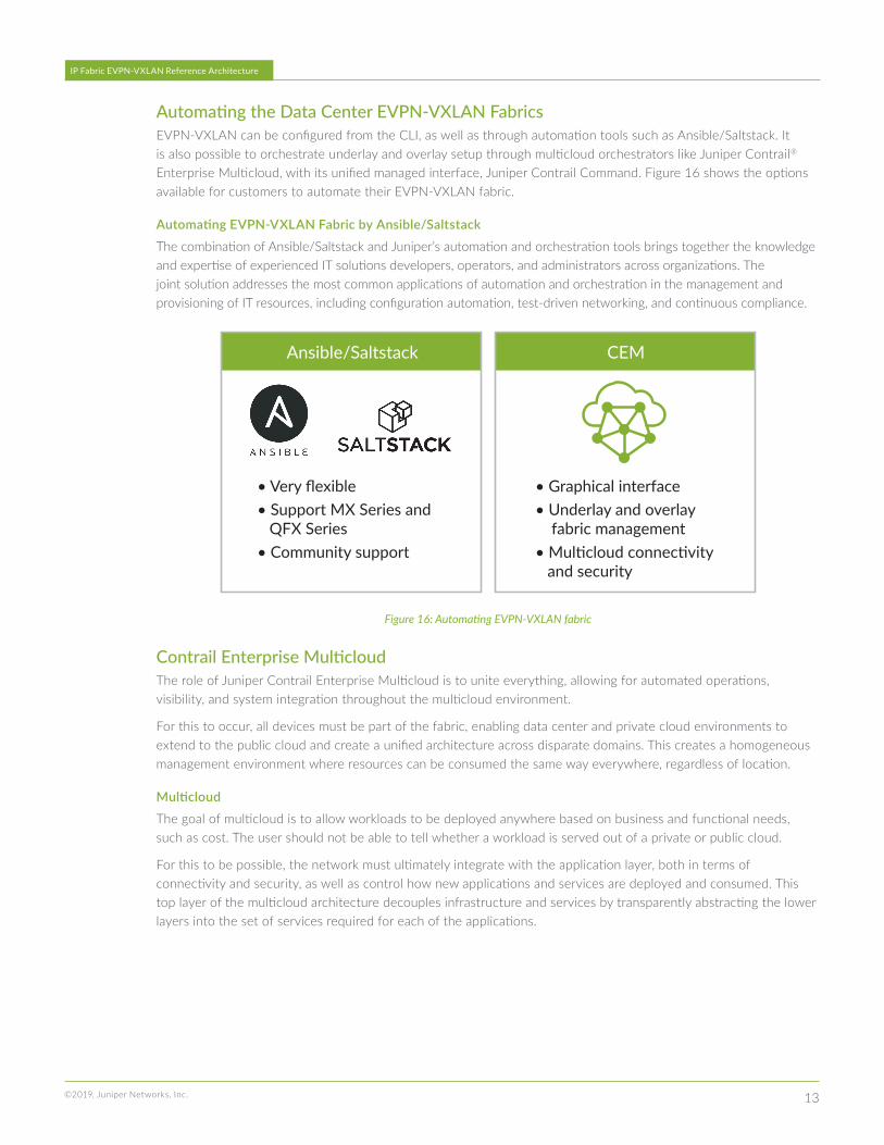
Automating the Data Center EVPN-VXLAN FabricsEVPN-VXLAN can be configured from the CLI, as well as through automation tools such as Ansible/Saltstack. It is also possible to orchestrate underlay and overlay setup through multicloud orchestrators like Juniper Contrail® Enterprise Multicloud, with its unified managed interface, Juniper Contrail Command. Figure 16 shows the options available for customers to automate their EVPN-VXLAN fabric.
Automating EVPN-VXLAN Fabric by Ansible/Saltstack The combination of Ansible/Saltstack and Juniper’s automation and orchestration tools brings together the knowledge and expertise of experienced IT solutions developers, operators, and administrators across organizations. The joint solution addresses the most common applications of automation and orchestration in the management and provisioning of IT resources, including configuration automation, test-driven networking, and continuous compliance.
Ansible/Saltstack CEM
• Very flexible• Support MX Series and QFX Series• Community support
• Graphical interface• Underlay and overlay fabric management• Multicloud connectivity and security
Figure 16: Automating EVPN-VXLAN fabric
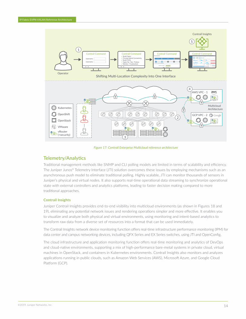
Contrail Enterprise Multicloud The role of Juniper Contrail Enterprise Multicloud is to unite everything, allowing for automated operations, visibility, and system integration throughout the multicloud environment.
For this to occur, all devices must be part of the fabric, enabling data center and private cloud environments to extend to the public cloud and create a unified architecture across disparate domains. This creates a homogeneous management environment where resources can be consumed the same way everywhere, regardless of location.
MulticloudThe goal of multicloud is to allow workloads to be deployed anywhere based on business and functional needs, such as cost. The user should not be able to tell whether a workload is served out of a private or public cloud.
For this to be possible, the network must ultimately integrate with the application layer, both in terms of connectivity and security, as well as control how new applications and services are deployed and consumed. This top layer of the multicloud architecture decouples infrastructure and services by transparently abstracting the lower layers into the set of services required for each of the applications.
14©2019, Juniper Networks, Inc.
IP Fabric EVPN-VXLAN Reference Architecture
Operator
Contrail Insights
GCP VPC - 2
MulticloudArchitecture
Contrail CommandContrail CommandContrail Command Contrail Command
Kubernetes
OpenShift
OpenStack
VMware
vRouter(+security)
Shifting Multi-Location Complexity Into One Interface
1
2
3
4
5
AWS VPC - 1
Username
Username
✓ Build Fabric✓ Provide Hybrid Connectivity✓ Build PODs✓ Apply Ne / Sec. Policies✓ Monitor / Troubleshoot
Figure 17: Contrail Enterprise Multicloud reference architecture
Telemetry/AnalyticsTraditional management methods like SNMP and CLI polling models are limited in terms of scalability and efficiency. The Juniper Junos® Telemetry Interface (JTI) solution overcomes these issues by employing mechanisms such as an asynchronous push model to eliminate traditional polling. Highly scalable, JTI can monitor thousands of sensors in Juniper’s physical and virtual nodes. It also supports real-time operational data streaming to synchronize operational state with external controllers and analytics platforms, leading to faster decision making compared to more traditional approaches.
Contrail InsightsJuniper Contrail Insights provides end-to-end visibility into multicloud environments (as shown in Figures 18 and 19), eliminating any potential network issues and rendering operations simpler and more effective. It enables you to visualize and analyze both physical and virtual environments, using monitoring and intent-based analytics to transform raw data from a diverse set of resources into a format that can be used immediately.
The Contrail Insights network device monitoring function offers real-time infrastructure performance monitoring (IPM) for data center and campus networking devices, including QFX Series and EX Series switches, using JTI and OpenConfig.
The cloud infrastructure and application monitoring function offers real-time monitoring and analytics of DevOps and cloud-native environments, supporting a mix of high-performance bare-metal systems in private cloud, virtual machines in OpenStack, and containers in Kubernetes environments. Contrail Insights also monitors and analyzes applications running in public clouds, such as Amazon Web Services (AWS), Microsoft Azure, and Google Cloud Platform (GCP).

15©2019, Juniper Networks, Inc.
IP Fabric EVPN-VXLAN Reference Architecture
Contrail Insights
Application and Services Cloud Infrastructure Software Defined Infrastructure Physical Infrastructure
Figure 18: Cross-layer visibility and analytics
Analytics
Analytics
Contrail Insights
Private Cloudswith anyworkload
TopologyDiscovery
State DrivenOrchestration
ContrailContrail
Contrail
Figure 19: Analytics in a Contrail Enterprise Multicloud environment

16
Corporate and Sales Headquarters
Juniper Networks, Inc.
1133 Innovation Way
Sunnyvale, CA 94089 USA
Phone: 888.JUNIPER (888.586.4737)
or +1.408.745.2000
Fax: +1.408.745.2100
www.juniper.net
Copyright 2019 Juniper Networks, Inc. All rights reserved. Juniper Networks, the Juniper Networks logo, Juniper, and Junos are registered trademarks of Juniper Networks, Inc.
in the United States and other countries. All other trademarks, service marks, registered marks, or registered service marks are the property of their respective owners. Juniper
Networks assumes no responsibility for any inaccuracies in this document. Juniper Networks reserves the right to change, modify, transfer, or otherwise revise this publication
without notice.
APAC and EMEA Headquarters
Juniper Networks International B.V.
Boeing Avenue 240
1119 PZ Schiphol-Rijk
Amsterdam, The Netherlands
Phone: +31.0.207.125.700
Fax: +31.0.207.125.701
8030015-002-EN Oct 2019
IP Fabric EVPN-VXLAN Reference Architecture
ConclusionJuniper’s EVPN-VXLAN deployment represents a modern, open, standards-based, and automation-native control plane that solves multiple technology problems, helping organizations move and handle data across legacy, on-premises, and cloud-based processing. Juniper’s participation in the design, standardization, and implementation of EVPN technology demonstrates the skills to solve the world’s most complex problems and validates Juniper’s guiding principle to drive engineering simplicity.
For more information about how to design and deploy overlay networks, please read the Cloud Data Center Blueprint Architecture Components in the Tech Library.
About Juniper NetworksJuniper Networks brings simplicity to networking with products, solutions, and services that connect the world. Through engineering innovation, we remove the constraints and complexities of networking in the cloud era to solve the toughest challenges our customers and partners face daily. At Juniper Networks, we believe that the network is a resource for sharing knowledge and human advancement that changes the world. We are committed to imagining groundbreaking ways to deliver automated, scalable, and secure networks to move at the speed of business.