Embed Size (px)
Citation preview

Refactoring Router Software to
Minimize Disruption
Eric Robert Keller
A Dissertation
Presented to the Faculty
of Princeton University
in Candidacy for the Degree
of Doctor of Philosophy
Recommended for Acceptance
by the Department of
Electrical Engineering
Adviser: Jennifer Rexford
November 2011

c© Copyright by Eric Robert Keller, 2011.
All rights reserved.
Abstract
Network operators are under tremendous pressure to make their networks highly
reliable to avoid service disruptions. Yet, operators often need to change the network
to upgrade faulty equipment, deploy new services, and install new routers. Unfortu-
nately, changes cause disruptions, forcing a trade-off between the benefit of the change
and the disruption it will cause. This disruption comes from the very design of the
routers and routing protocols underlying the Internet’s operation. First, since the
Internet is composed of many smaller networks, in order to determine a path between
two end points, a distributed calculation involving many of the networks is necessary.
Therefore, during any network event that requires a calculation, there will be a pe-
riod of time when there are disagreements among the routers in the various networks,
potentially leading to the situation where there is no path available between some
end points. Second, selecting routes involves computations across millions of routers
spread over vast distances, multiple routing protocols, and highly customizable rout-
ing policies. This leads to very complex software systems. Like any complex software,
routing software is prone to implementation errors, or bugs. Given these disruptions,
operators must make tremendous effort to minimize their effect. Not only does this
lead to a lot of human effort, it also increases the opportunity for mistakes in the
configuration – a common cause of outages.
We believe that with a refactoring of today’s router software we can make the
network infrastructure more accommodating of change, and therefore more reliable
and easier to manage.
First, we tailor software and data diversity (SDD) to the unique properties of
routing protocols, so as to avoid buggy behavior at run time. Our bug-tolerant router
executes multiple diverse instances of routing software, and uses voting to determine
the output to publish to the forwarding table, or to advertise to neighbors. We
designed and implemented a router hypervisor that makes this parallelism transparent
iii

to other routers, handles fault detection and booting of new router instances, and
performs voting in the presence of routing-protocol dynamics, without needing to
modify software of the diverse instances.
Second, we argue that breaking the tight coupling between the physical and logical
configurations of a network can provide a single, general abstraction that simplifies
network management. Specifically, we propose VROOM (Virtual ROuters On the
Move), a new network-management primitive where virtual routers can move freely
from one physical router to another. We present the design, implementation, and
evaluation of novel migration techniques for virtual routers with either hardware or
software data planes.
Finally, we introduce the concept of router grafting. This capability allows an
operator to rehome a customer with no disruption, compared to downtimes today
measured in minutes. With our architecture, this rehoming can be performed com-
pletely transparently from the neighboring network – where the customer’s router is
not modified and is unaware migration is happening.
Together, these three modifications enable network operators to perform the
desired change on their network without (i) possibly triggering bugs in routers that
causes Internet-wide instability, (ii) causing unnecessary network re-convergence
events, (iii) having to coordinate with neighboring network operators, or (iv) needing
an Internet-wide upgrade to new routing protocols.
iv

Acknowledgements
First and foremost, I would like to thank my family. To my wife, Kristen, I might
have been crazy to do this, but you were there supporting me every step of the way.
To my children, Braden and Devin, you amaze me each and every day. Maybe you’ll
read this one day when you’re older and understand what I was doing all those years.
And to my mom, your strength helped push me to finish what I started.
I will be forever indebted to my advisor, Jennifer Rexford. She gave me the space
I needed to be creative, the guidance I needed to do great work, and provided me
with the tools to be a great researcher for life. I cannot find the words to express how
amazing of a person she is. To work with her was such a great experience and I feel
very fortunate that I had this opportunity. I can only hope to help future students
like she has helped me.
I would like to thank my committee for their great help in completing this dis-
sertation – Kobus van der Merwe, Matthew Caesar, Ruby Lee, and Mung Chiang.
Kobus and Matt were also significant contributors and mentors in the technical direc-
tion of this dissertation (Kobus on the VROOM and Grafting work and Matt on the
Bug-Tolerant Router work). Their insight, knowledge, and guidance were invaluable.
Ruby and I worked closely together on research that falls outside of the scope of this
dissertation. She taught me a great deal about security and has gotten me very exited
about the field.
I would also like to thank other direct contributors to this dissertation – Minlan
Yu, Yi Wang, and Michael Schapira. Not only did collaborating with them directly
help this dissertation, but they are great people and it was a pleasure working with
each of them.
I would also like to thank Andy Bavier, Mike Freedman, and Rob Harrison for
their incredible feedback on the many things I’ve worked on at Princeton. I credit
Andy for teaching me a lot about how to write a paper. And I would similarly like
v

to thank Jakub Szefer for our work together on NoHype. We pushed though and
achieved something great with that.
I came to Princeton after seven years working for Xilinx. I owe a lot to Phil James-
Roxby (who actually proof read all of my papers at Princeton), Gordon Brebner, and
Steve Guccione for being great friends and mentors, even after I left. Having three
great people to lean on over the years helped a lot (from deciding to go back to
school, to applying, to pushing through those middle years of the Ph.D. when the
initial excitement has worn off but there is still a long time left).
Similarly, grad school wouldn’t be grad school without my fellow students. I
would like to thank my friends in the electrical engineering and computer science
departments and in particular the rest of the Cabernet group (past and present). It
was great fun knowing them and learning from them.
And finally, I would like to thank Intel for the fellowship during my final year.
vi

I dedicate this dissertation to the memory of my dad, Robert Keller.
He was the one who introduced me to computers at a young age – going all the way
back to the TRS-80. I wish he could have been here to see me finish, but I’m
thankful he at least got to see me start.
vii

Contents
Abstract . . . . . . . . . . . . . . . . . . . . . . . . . . . . . . . . . . . . . iii
Acknowledgments . . . . . . . . . . . . . . . . . . . . . . . . . . . . . . . . v
List of Tables . . . . . . . . . . . . . . . . . . . . . . . . . . . . . . . . . . xiii
List of Figures . . . . . . . . . . . . . . . . . . . . . . . . . . . . . . . . . . xiv
1 Introduction 1
1.1 Change Happens . . . . . . . . . . . . . . . . . . . . . . . . . . . . . 2
1.1.1 Equipment Failure . . . . . . . . . . . . . . . . . . . . . . . . 3
1.1.2 Planned Maintenance of Equipment and Software . . . . . . . 4
1.1.3 Updated Inter-domain Policy and Connectivity . . . . . . . . 4
1.1.4 Changes to Optimize Resource Utilization . . . . . . . . . . . 6
1.1.5 Service Deployment and Evolution . . . . . . . . . . . . . . . 7
1.2 Change is Painful . . . . . . . . . . . . . . . . . . . . . . . . . . . . . 8
1.2.1 Because Routing Software is Distributed . . . . . . . . . . . . 8
1.2.2 Because Routing Software is Complex . . . . . . . . . . . . . . 9
1.2.3 Because Routing Software is Configurable . . . . . . . . . . . 11
1.3 Refactoring Router Software . . . . . . . . . . . . . . . . . . . . . . . 12
1.4 Router Trends . . . . . . . . . . . . . . . . . . . . . . . . . . . . . . . 15
2 Hiding Routing Software Bugs from Adjacent Routers with the Bug-
Tolerant Router 20
viii

2.1 Introduction . . . . . . . . . . . . . . . . . . . . . . . . . . . . . . . . 20
2.1.1 Challenges in dealing with router bugs . . . . . . . . . . . . . 20
2.1.2 The case for diverse replication in routers . . . . . . . . . . . . 22
2.1.3 Designing a Bug-Tolerant Router . . . . . . . . . . . . . . . . 23
2.2 Software and Data Diversity in Routers . . . . . . . . . . . . . . . . . 24
2.2.1 Diversity in the software environment . . . . . . . . . . . . . . 25
2.2.2 Execution environment diversity . . . . . . . . . . . . . . . . . 29
2.2.3 Protocol diversity . . . . . . . . . . . . . . . . . . . . . . . . . 30
2.3 Bug Tolerant Router (BTR) . . . . . . . . . . . . . . . . . . . . . . . 31
2.3.1 Making replication transparent . . . . . . . . . . . . . . . . . 31
2.3.2 Dealing with the transient and real-time nature of routers . . 34
2.4 Router Hypervisor Prototype . . . . . . . . . . . . . . . . . . . . . . 36
2.4.1 Wrapping the routing software . . . . . . . . . . . . . . . . . . 37
2.4.2 Detecting and recovering from faults . . . . . . . . . . . . . . 38
2.4.3 Reducing complexity . . . . . . . . . . . . . . . . . . . . . . . 39
2.5 Evaluation . . . . . . . . . . . . . . . . . . . . . . . . . . . . . . . . . 41
2.5.1 Voting in the presence of churn . . . . . . . . . . . . . . . . . 42
2.5.2 Processing overhead . . . . . . . . . . . . . . . . . . . . . . . 47
2.5.3 Effect on convergence . . . . . . . . . . . . . . . . . . . . . . . 48
2.6 Discussion . . . . . . . . . . . . . . . . . . . . . . . . . . . . . . . . . 50
2.7 Related Work . . . . . . . . . . . . . . . . . . . . . . . . . . . . . . . 52
2.8 Summary . . . . . . . . . . . . . . . . . . . . . . . . . . . . . . . . . 54
3 Decoupling the Logical IP-layer Topology from the Physical Topol-
ogy with VROOM 55
3.1 Introduction . . . . . . . . . . . . . . . . . . . . . . . . . . . . . . . . 55
3.2 Background . . . . . . . . . . . . . . . . . . . . . . . . . . . . . . . . 59
3.2.1 Flexible Link Migration . . . . . . . . . . . . . . . . . . . . . 59
ix

3.2.2 Related Work . . . . . . . . . . . . . . . . . . . . . . . . . . . 61
3.3 Network Management Tasks . . . . . . . . . . . . . . . . . . . . . . . 63
3.3.1 Planned Maintenance . . . . . . . . . . . . . . . . . . . . . . . 63
3.3.2 Service Deployment and Evolution . . . . . . . . . . . . . . . 64
3.3.3 Power Savings . . . . . . . . . . . . . . . . . . . . . . . . . . . 65
3.4 VROOM Architecture . . . . . . . . . . . . . . . . . . . . . . . . . . 66
3.4.1 Making Virtual Routers Migratable . . . . . . . . . . . . . . . 67
3.4.2 Virtual Router Migration Process . . . . . . . . . . . . . . . . 69
3.5 Prototype Implementation . . . . . . . . . . . . . . . . . . . . . . . . 73
3.5.1 Enabling Virtual Router Migration . . . . . . . . . . . . . . . 74
3.5.2 Realizing Virtual Router Migration . . . . . . . . . . . . . . . 77
3.6 Evaluation . . . . . . . . . . . . . . . . . . . . . . . . . . . . . . . . . 79
3.6.1 Methodology . . . . . . . . . . . . . . . . . . . . . . . . . . . 79
3.6.2 Performance of Migration Steps . . . . . . . . . . . . . . . . . 81
3.6.3 Data Plane Impact . . . . . . . . . . . . . . . . . . . . . . . . 82
3.6.4 Control Plane Impact . . . . . . . . . . . . . . . . . . . . . . . 86
3.7 Migration Scheduling . . . . . . . . . . . . . . . . . . . . . . . . . . . 88
3.8 Summary . . . . . . . . . . . . . . . . . . . . . . . . . . . . . . . . . 89
4 Seamless Edge Link Migration with Router Grafting 91
4.1 Introduction . . . . . . . . . . . . . . . . . . . . . . . . . . . . . . . . 91
4.1.1 A Case for Router Grafting . . . . . . . . . . . . . . . . . . . 92
4.1.2 Challenges and Contributions . . . . . . . . . . . . . . . . . . 94
4.2 BGP Routing Within a Single AS . . . . . . . . . . . . . . . . . . . . 97
4.2.1 Protocol Layers: IP, TCP, & BGP . . . . . . . . . . . . . . . 97
4.2.2 Components: Blades, Routers, & ASes . . . . . . . . . . . . . 99
4.3 Router Grafting Architecture . . . . . . . . . . . . . . . . . . . . . . 100
4.3.1 Copying BGP Session Configuration . . . . . . . . . . . . . . 101
x

4.3.2 Exporting & Resetting Run-Time State . . . . . . . . . . . . . 103
4.3.3 Migrating TCP Connection & IP Link . . . . . . . . . . . . . 105
4.3.4 Importing BGP Routing State . . . . . . . . . . . . . . . . . . 106
4.4 Correct Routing and Forwarding . . . . . . . . . . . . . . . . . . . . . 108
4.4.1 Control Plane: BGP Routing State . . . . . . . . . . . . . . . 108
4.4.2 Data Plane: Packet Forwarding . . . . . . . . . . . . . . . . . 110
4.5 BGP Grafting Prototype . . . . . . . . . . . . . . . . . . . . . . . . . 111
4.5.1 Configuring the Migrate-To Router . . . . . . . . . . . . . . . 112
4.5.2 Exporting Migrate-From BGP State . . . . . . . . . . . . . . 112
4.5.3 Exporting Migrate-From TCP State . . . . . . . . . . . . . . . 113
4.5.4 Importing the TCP State . . . . . . . . . . . . . . . . . . . . 113
4.5.5 Migrating the Layer-Three Link . . . . . . . . . . . . . . . . . 114
4.5.6 Importing Routing State . . . . . . . . . . . . . . . . . . . . . 115
4.6 Optimizations for Reducing Impact . . . . . . . . . . . . . . . . . . . 115
4.6.1 Reducing Impact on eBGP Sessions . . . . . . . . . . . . . . . 115
4.6.2 Reducing Impact on iBGP Sessions . . . . . . . . . . . . . . . 117
4.6.3 Eliminating Processing Entirely . . . . . . . . . . . . . . . . . 118
4.7 Performance Evaluation . . . . . . . . . . . . . . . . . . . . . . . . . 119
4.7.1 Grafting Delay and Overhead . . . . . . . . . . . . . . . . . . 119
4.7.2 Optimizations for Reducing Impact . . . . . . . . . . . . . . . 121
4.8 Traffic Engineering with Grafting . . . . . . . . . . . . . . . . . . . . 124
4.8.1 Traffic Engineering Today . . . . . . . . . . . . . . . . . . . . 124
4.8.2 Migration-Aware Traffic Engineering . . . . . . . . . . . . . . 125
4.8.3 Practical Considerations . . . . . . . . . . . . . . . . . . . . . 128
4.8.4 The Max-Link Heuristic . . . . . . . . . . . . . . . . . . . . . 129
4.8.5 Experimental Results on Internet2 . . . . . . . . . . . . . . . 130
4.8.6 Migration Improves Network Utilization . . . . . . . . . . . . 131
xi

4.8.7 Frequent Migration is Not Necessary . . . . . . . . . . . . . . 134
4.8.8 Only a Fraction of Links Need to be Migrated . . . . . . . . . 135
4.9 Related Work . . . . . . . . . . . . . . . . . . . . . . . . . . . . . . . 137
4.10 Summary . . . . . . . . . . . . . . . . . . . . . . . . . . . . . . . . . 139
5 Conclusion 140
5.1 Summary of Contributions . . . . . . . . . . . . . . . . . . . . . . . . 140
5.2 A Unified Architecture . . . . . . . . . . . . . . . . . . . . . . . . . . 143
5.3 Future Work . . . . . . . . . . . . . . . . . . . . . . . . . . . . . . . . 146
5.3.1 Monitoring in Addition to Voting for a Bug-Tolerant Router . 146
5.3.2 Hosted and Shared Network Infrastructure with VROOM . . . 146
5.3.3 Router Grafting for Security . . . . . . . . . . . . . . . . . . . 147
5.4 Concluding Remarks . . . . . . . . . . . . . . . . . . . . . . . . . . . 148
Bibliography 149
xii

List of Tables
2.1 Example bugs and the diversity that can be used to avoid them. . . . 26
3.1 The memory dump file size of virtual router with different numbers of
OSPF routes . . . . . . . . . . . . . . . . . . . . . . . . . . . . . . . 82
3.2 The FIB repopulating time of the SD and HD prototypes . . . . . . . 82
3.3 Packet loss rate of the data traffic, with and without migration traffic 85
4.1 Summary of notation used in model of traffic engineering with migration.126
4.2 Comparison of the improvement over the original topology optimized
for routing only when performing grafting at different intervals (over 7
days traffic). . . . . . . . . . . . . . . . . . . . . . . . . . . . . . . . . 135
xiii

List of Figures
1.1 Generic diagram of a router design. . . . . . . . . . . . . . . . . . . . 3
1.2 Generic network of networks consisting of end users and autonomous
systems. . . . . . . . . . . . . . . . . . . . . . . . . . . . . . . . . . . 5
1.3 Generic network consisting of routers and links. . . . . . . . . . . . . 7
1.4 Router software architecture. . . . . . . . . . . . . . . . . . . . . . . . 10
1.5 Router software refactoring. . . . . . . . . . . . . . . . . . . . . . . . 18
1.6 Router trends. . . . . . . . . . . . . . . . . . . . . . . . . . . . . . . . 19
2.1 Architecture of a bug-tolerant router. . . . . . . . . . . . . . . . . . 32
2.2 Implementation architecture. . . . . . . . . . . . . . . . . . . . . . . . 37
2.3 Effect of bug duration on fault rate, holding bug interarrival times fixed at
1.2 million seconds. . . . . . . . . . . . . . . . . . . . . . . . . . . . . 43
2.4 Effect of bug interval on fault rate, holding bug duration fixed at 600 sec-
onds. . . . . . . . . . . . . . . . . . . . . . . . . . . . . . . . . . . . 43
2.5 Effect of voting on update overhead. . . . . . . . . . . . . . . . . . . . 46
2.6 Effect of convergence time threshold. . . . . . . . . . . . . . . . . . . . 46
2.7 BTR pass-through time. . . . . . . . . . . . . . . . . . . . . . . . . . . 48
2.8 Network-wide simulations, per-router convergence delay distribution. . . 49
3.1 Link migration in the transport networks . . . . . . . . . . . . . . . . 59
3.2 The architecture of a VROOM router . . . . . . . . . . . . . . . . . . 67
xiv

3.3 VROOM’s novel router migration mechanisms (the times at the bottom
of the subfigures correspond to those in Figure 3.4) . . . . . . . . . . 67
3.4 VROOM’s router migration process . . . . . . . . . . . . . . . . . . . 69
3.5 The design of the VROOM prototype routers (with two types of data
planes) . . . . . . . . . . . . . . . . . . . . . . . . . . . . . . . . . . . 74
3.6 The diamond testbed and the experiment process . . . . . . . . . . . 79
3.7 The Abilene testbed . . . . . . . . . . . . . . . . . . . . . . . . . . . 81
3.8 Virtual router memory-copy time with different numbers of routes . . 81
3.9 Delay increase of the data traffic, due to bandwidth contention with
migration traffic . . . . . . . . . . . . . . . . . . . . . . . . . . . . . . 85
4.1 Migration protocol layers. . . . . . . . . . . . . . . . . . . . . . . . . 97
4.2 Migrating the session with X between route processor blades (from
RP1 to RP2). . . . . . . . . . . . . . . . . . . . . . . . . . . . . . . . 100
4.3 Migrating session with A between routers (from B to C). . . . . . . . 101
4.4 Router grafting mechanisms – migrating a session with Router A (not
shown) from router Migrate-from to router Migrate-to. The boxes marked
bgpd and network stack are the software programs. The boxes marked
RIBA, configA, and TCPA are the routing, configuration, and TCP state
respectively. . . . . . . . . . . . . . . . . . . . . . . . . . . . . . . . . 102
4.5 A topology where AS 200 has migrate-from router A, migrate-to router
B, internal router F, and external routers C, D, and G, and remote
end-point E. . . . . . . . . . . . . . . . . . . . . . . . . . . . . . . . 107
4.6 The router grafting prototype system. . . . . . . . . . . . . . . . . . . 111
4.7 BGP session grafting time vs. RIB size. . . . . . . . . . . . . . . . . . 120
4.8 The CPU utilization at the migrate-to router during migration, with
a 200k prefix RIB. . . . . . . . . . . . . . . . . . . . . . . . . . . . . 121
4.9 Updates sent as a result of migration. . . . . . . . . . . . . . . . . . . . 122
xv

4.10 Network model for traffic engineering with migration. . . . . . . . . . 126
4.11 Evaluation of max-link for a single 5-minute period. . . . . . . . . . . 132
4.12 Evaluation of max-link over 7 days of traffic – time-series. . . . . . . . 134
4.13 Evaluation of max-link over 7 days of traffic – cumulative distribution
function. . . . . . . . . . . . . . . . . . . . . . . . . . . . . . . . . . . 134
4.14 Fraction of traffic each user node sends in an example 5-minute period. 136
4.15 Cumulative distribution function of the number of links that need to
be migrated during each interval over 7 days of traffic (2016 5-minute
intervals). Shown are three lines corresponding to different thresholds
– only links in the top X% of traffic are migrated. . . . . . . . . . . . 137
5.1 Unified architecture. . . . . . . . . . . . . . . . . . . . . . . . . . . . 143
xvi

Chapter 1
Introduction
The Internet has become an integral part of our lives. Not only do many of us have
high speed connections at our homes, we also have data connections on our mobile
devices as well as work at businesses that provide or rely on software accessible across
a network. In order to be able to visit a website, use a web service, or use any dis-
tributed software, the underlying infrastructure must provide reachability, and more
specifically the Internet as a whole must provide global reachability – i.e., any net-
worked device can communicate with any other networked device, so long as those
networked devices are not explicitly blocking the communication. To provide this
global reachability, the elements in the network infrastructure (i.e., the routers) com-
municate with one another to determine the paths to take to reach each destination.
Any change to the underlying infrastructure, such as adding new equipment or per-
forming maintenance on the existing equipment, causes the routers to determine a
new set of paths. Given the expansiveness of the Internet, changes are continually
occurring. Not only do these changes cause transient disruptions while new paths are
determined but they can also cause longer term disruptions where some destinations
are unreachable for an extended period. For the most part, the current Internet does
a reasonably good job at minimizing disruptions thanks to the tireless effort of the
1

many network operators. Moving forward, this task will be increasingly difficult as
(i) the size of the Internet grows, and (ii) applications which have more significant
demands in terms of availability, such as remote health care and a smart power grid,
become more common. We believe that with a refactoring of today’s router soft-
ware we can make the network infrastructure more accommodating of change, and
therefore more reliable and easier to manage. In this chapter we first present some
background on the network management tasks necessary to operate a network (Sec-
tion 1.1) and the disruption that the associated changes in the network infrastructure
can cause (Section 1.2). We then detail our proposal to refactor router software in
order to accommodate these changes without disruption (Section 1.3). We wrap up
with a discussion of some recent trends in router design that enable this refactoring
that is seemingly impossible to realize in practice (Section 1.4).
1.1 Change Happens
To many, the Internet can be represented as a big cloud on a diagram connecting
end users of some service (e.g., a web site) to the servers that host that service. Of
course, in reality, the Internet is a federation of thousands of independently controlled
networks. To determine how to reach a particular destination, the network elements
known as routers essentially communicate with one another (both within the same
network and between neighboring networks) to disseminate information about avail-
able paths.
These routers are in constant communication as the Internet is constantly chang-
ing. Each individual network often undergoes some changes during the normal course
of operation. To understand the different types of change, in this section, we overview
several reasons for change.
2

1.1.1 Equipment Failure
As routers are physical, electronic equipment, the components within them are sus-
ceptible to failure. Routers have several important components, as shown in Figure
1.1. The interface cards have the connectors to the actual cables along with cus-
tom hardware to process each packet (e.g., decide which output port to forward the
packet on). The switching fabric, which is many times multiple cards, provide a high
bandwidth and low latency connection between each of the line cards. The route
processors run the software that computes the routing decisions such as determining
the paths that should be taken through the network. There are commonly multiple
route processors in order to handle the processing load required. Of course there are
additional required components such as power supplies and fans. Failure of those,
such as through a power outage, will cause the router to fail. Finally, the cables
connecting routers together, either electrical or optical, can also fail. Here the failure
is more likely in terms of physical damage (e.g., a cut) to the cable either due to
weather, construction, or vandals.
Figure 1.1: Generic diagram of a router design.
3

1.1.2 Planned Maintenance of Equipment and Software
Planned maintenance is a fact of life for network operators. Many times this comes
in the form of an upgrade to the network or network components. In order to keep
the network up-to-date, network operators routinely upgrade the routing software or
patch the firmware in the interface cards to include the latest bug fixes and features.
They may also need to add routers to keep up with growth or replace older equipment
with newer versions. Planned maintenance may also come in the form of a preventa-
tive measure to address a possible problem before it arises and causes more significant
disruption. If components are showing signs of failure, such as due to increased error
rates, operators can replace the individual components in the modularly designed
routers.
1.1.3 Updated Inter-domain Policy and Connectivity
Beyond failure and maintenance of the equipment, change comes from managing the
operation of the network. As illustrated in Figure 1.2, the Internet is composed of a
network of networks – each is known as an autonomous system (AS) and is run by
a different party. Through routing protocols, these networks exchange information
about the availability of paths so that the end users (clients, shown as home users,
and servers, shown as data centers) spread throughout the Internet can communicate
with one another. For example, AS5 will announce to its neighbors (AS1 and AS4)
that they can go through AS5 to reach the block of IP addresses owned by data center
A. This information will propagate throughout the network and eventually reach AS6
where it will know a path by which its customers (the home users) can reach the web
service running in data center A.
By configuring the individual routers, network operators can specify policies about
which paths are preferred and what information should not be told to specific neigh-
boring networks. For example, AS4 might be a paying customer of AS2, so AS4 might
4

not tell AS2 that AS2 can reach data center A through AS4. Each change in policy
is a change that can have Internet wide impact (or at least, impact the neighboring
networks).
In managing the network, it may become necessary or highly desirable to change
which internal edge router a given neighboring network connects to, or even which
route processor within a router handles the routing session. This might be for load
balancing purposes where one router is overloaded, so the network operator changes
the router (or route processor) which handles the routing session with the neighboring
network. Such changing of edge routers might alternatively be simply to support a
customer request. Networks consist of a heterogeneous collection of routers, both in
terms of vendor and in terms of model. As such, not all routers support the same
features. If an existing customer changes some requirements, such as requesting a
new quality of service feature, that is not supported on the edge router it is currently
connected to, network operators must change the handling of that connection to
another router.
Figure 1.2: Generic network of networks consisting of end users and autonomoussystems.
5

1.1.4 Changes to Optimize Resource Utilization
Network operators must also manage the resources within their own network (e.g.,
the available bandwidth of links, compute power of routers, and electric power of
network operation centers). Similar to determining paths throughout the Internet,
routing protocols are also used within one network to determine paths between ingress
and egress points. For example, in the example network in Figure 1.3, to reach
destination dest1 from router A, a routing protocol might decide to follow the path
A→C→D. Routing decisions can also be based on more than simply the shortest
distance. Traffic engineering is the act of reconfiguring the network to optimize the
flow of traffic, to minimize congestion. Today, traffic engineering involves adjusting
the routing-protocol parameters to coax the routers into computing new paths that
better match the offered traffic. For example, if the link between C and D is congested,
a network operator might prefer to re-route some of that traffic to follow C→B→D
instead of C→D directly.
In addition to making traffic flow more efficiently within the network, operators
can take advantage of the mostly predictable variations in traffic volumes in order to
save power. It was reported that in 2000 the total power consumption of the estimated
3.26 million routers in the U.S. was about 1.1 TWh (Tera-Watt hours) [91]. This
number was expected to grow to 1.9 to 2.4TWh in the year 2005 by three different
projection models [91], which translates into an annual cost of about 178-225 million
dollars [81]. These numbers do not include the power consumption of the required
cooling systems. However, today’s routers are surprisingly power-insensitive to the
traffic loads they are handling—an idle router consumes over 90% of the power it
requires when working at maximum capacity [31]. Instead, operators must shut off
some routers during periods of lower traffic in order to save power. To make the traffic
that is handled by the router that is being shut down flow through a different router,
6

the operator needs to configure the routers in a similar manner as is done with traffic
engineering.
Figure 1.3: Generic network consisting of routers and links.
1.1.5 Service Deployment and Evolution
Deploying new services, like IPv6 or IPTV, is yet another reason for changes to net-
works. Here, ISPs usually start with a small trial running in a controlled environment
on dedicated equipment, supporting a few early-adopter customers. This is to ensure
that (i) the new services do not adversely impact existing services, and (ii) the neces-
sary support systems are in place before services can be properly supported1. As the
service moves past the initial test phase and into wider deployment, the ISP will need
to restructure their test network, or move the service onto a larger network to serve
a larger set of customers. This roll-out is a substantial change to the network as it
effectively requires merging the configurations of the routers on one network into the
routers on another network and resolving any conflicts that arise. Not only are the
configurations merged, but the service is also expanded to be run on more routers,
which require new configurations.
1Support systems include configuration management, service monitoring, provisioning, andbilling.
7

1.2 Change is Painful
Whether it’s a change in topology or a change in policy/preferences, whenever a
change does occur, that information must get disseminated throughout the Internet.
This is achieved through routing protocols, which are realized in the form of software
running on each router. Here, complexity comes from (i) the distributed (in terms of
many nodes working together to come to an agreement) and decentralized (in terms
of authority) nature of inter-domain routing, (ii) the substantial software running on
each router realizing these protocols, and (iii) the configurability of this software in
order to support a wide variety of situations. Because of this complexity, change is
painful.
1.2.1 Because Routing Software is Distributed
Focusing on a single routing protocol, the border gateway protocol (BGP) is the
protocol used between networks under different administrative control (i.e., the au-
tonomous systems) in order to exchange available routes. Each route indicates some
properties about the path to the destination, such as which sequence of autonomous
systems will be traversed by traffic taking that route. At its core, there are two prim-
itive update messages: (i) announce the availability of a path to a given destination,
and (ii) withdraw the availability of a path to a given destination2.
When a router receives an update, that indicates that the state of the network has
changed. That router will re-run its own decision process to determine the impact
on routes that it has chosen to use. If there is any change, the router will notify its
neighbors. They, in turn will do the same thing. Where this causes a problem is that
the changes they (or neighbors further down the line) make may affect the decisions
2Subsequent announcements about a previously announced prefix effectively replaces the previousannouncement – only the most recent announcement for a particular destination is valid.
8

being made at this router. Therefore, as it is a distributed decision making process,
there will be a period of time when there is disagreement within the network.
When this occurs, such issues as black holes and loops occur. A black hole is
when the routes used by one network sends data traffic to another network thinking
that network has a path to the destination. The black hole occurs when that network
does not know a path to the destination, so it drops the traffic. Loops are where data
traffic continuously traverses the same networks without reaching the destination.
For example, network A thinks the path to the destination goes through Network B,
but B thinks the path to the destination goes through A. So, A sends its traffic to B,
who sends the traffic to A, and the traffic keeps going around.
An added complication is that it takes time to process each change. In order to
not overwhelm the routers’ processing capabilities, the use of timers has become com-
monplace. For example, the MinRouteAdvertisementInterval (MRAI) [85] parameter
in BGP is used to limit the sending of updates to once per interval (today a value
of 30sec is common). Unfortunately, this makes it take longer for the network to
come to an agreement as the MRAI delays how quickly an update can make its way
throughout the network.
1.2.2 Because Routing Software is Complex
Selecting routes involves computations across millions of routers spread over vast
distances, multiple routing protocols, and highly customizable routing policies. This
leads to very complex software systems.
As shown in Figure 1.4(a), these routers typically run an operating system, and
a collection of protocol daemons which implement the various tasks associated with
protocol operation. For example, shown are BGP, which is used for inter-domain
routing (i.e., communicating with external networks), OSPF (Open Shortest Path
First), which is used for intra-domain routing (determining paths within the net-
9

work), and a command line for configuring static routes. The BGP process needs to
know the routes chosen by OSPF because the internal network distance is used in
BGP’s calculation for selecting routes. For this, a route distributer will perform this
distribution.
In Figure 1.4(b), the BGP routing process is shown. For each neighbor of the
router, the process must maintain a session. This includes typical Unix sockets type
functionality, as well as maintaining a state machine to track the various BGP states.
The stream of incoming data is split up into update messages and passed to the in-
coming filter, which will drop or modify routes based on the router’s configuration.
The update is then sent to the decision process, which performs the main functional-
ity of the protocol – updating the RIB with the received update, reading from the the
routing information base (RIB) the routes for that same prefix from the other neigh-
bors, and deciding which of the routes is best based on the configurable preferences.
The chosen route is then passed to each of the outgoing filters, one per neighbor,
where based on the configuration, the filter can drop or modify the route. Finally,
the update is sent to the neighboring router, possibly after some delay (e.g., based
on the MRAI timer).
(a) System-wide router software.(b)BGP software architecture.
Figure 1.4: Router software architecture.
Like any complex software, routing software is prone to implementation errors, or
bugs. Due to the critical nature of routers in today’s Internet, the effect of a bug in
one of the routers can be tremendous and far reaching. This complexity has led to
10

several major Internet wide outages recently [87, 89, 86]. In each case, a legitimate
configuration change in one network caused an update to be sent which eventually
triggered a bug. This is especially damaging since there are only a limited number
router vendors and models. So, a single update can be propagated throughout the
network (in all directions), and trigger the bug on a number of routers. This then
causes those routers to send out bogus updates, which can either cause neighboring
routers to shutdown the session (if the bogus update was malformed) or actually use
and propagate the bogus route. The latter case is especially damaging since byzantine
faults are harder to detect and localize than a bug which causes a crash. Luckily, a
coordinated attack on the Internet routing system that exploits these bugs has not
occurred yet. Though, that would be a possible way to create a ‘cyber-nuke’[88].
1.2.3 Because Routing Software is Configurable
Because of the effects change can have, operators must go out of their way to minimize
the disruption. In fact, the cost of the people and systems that manage a network
typically exceeds the cost of the underlying nodes and links [68]. Consider an example
where a router needs to be replaced. In some cases, it is possible to avoid a disruption
due to the router going down through a series of reconfigurations which gradually
changes the routing protocol parameters to coax traffic to not go through the router in
question [50][51]. Of course, the side effects of a reconfiguration, such as convergence
and triggering router bugs, will still exist and can cause disruption. Further, being a
human process, errors in the configurations can and do occur. Most network outages
are actually caused by operator errors, rather than equipment failure [68].
Even if the operator is careful and the process can be automated, given the large
and distributed nature of the Internet, an operator does not really know the full effect
of a given change before it is made. A network operator might alter the configuration
of a router, e.g., to change which provider is preferred, which causes a previously
11

unused (but known) route to now be selected. This new route might actually be a
black hole that the operator did not know about. While black holes can happen as
a transient behavior of the convergence process, black holes can last for hours, even
days [64]. Tracking down connectivity problems is a huge effort for operators.
1.3 Refactoring Router Software
In order to better accommodate change in the Internet, we propose refactoring the
router software. We first want to enable network operators to make changes, which
if they are really just local changes, do not have any external impact. For those
changes that do have an impact external to the network making the change, the
changes should not cause harmful network-wide effects. Our approach is to redesign
the routers rather than the routing protocols. With this, network operators can
immediately gain benefits without having to coordinate with neighboring network
operators or waiting for a Internet-wide upgrade to some new protocol.
As illustrated in Figure 1.5, the refactoring we are suggesting can be categorized by
the various levels at which a network and the network components can be viewed and
how they interact with other layers. For each boundary between layers, we provide a
system that breaks the tight coupling between the layers. In doing so, the underlying
infrastructure is more accommodating of change. Each is briefly introduced below,
with more detail in the chapters dedicated to each system.
Between the router software and the neighboring routers in the network
(Chapter 2): The software running on routers is large and complex, and therefore
can be quite buggy. In order for the rest of the network to operate properly, we
are reliant on this single piece of software to behave correctly. A buggy router can
send bogus messages to the neighboring routers. We propose breaking this reliance
on a single router software implementation. While providing the view of a single
12

router instance to the operator and neighboring routers, with the Bug-tolerant router,
we internally restructure the software to allow multiple, diverse instances of router
software to run in parallel [67]. In doing so we are able to mask errors in any single
implementation. We make the case why this approach is necessary, effective, and
possible. We also describe an architecture which deals with the unique properties
of routing software – doing so while hiding the multiple instances and churn among
the instances from both the network operator and neighboring routers. We built a
prototype implementation consisting of a set of extensions built on top of Linux and
tested with multiple version of XORP [9], Quagga [6], and BIRD [1]. Experiments
with BGP message traces and the open-source routing software running on our Linux-
based router hypervisor demonstrate that our solution scales to large networks and
efficiently masks buggy behavior.
Between the physical topology of routers and the logical IP layer topology
of routers (Chapter 3): The routing protocols work at the IP layer, essentially
viewing routers as nodes in a graph and determining paths between nodes. However,
this IP layer logical topology is tightly coupled to the underlying physical network.
If an operator needs to, for example, shut down a physical router to perform some
maintenance (e.g., replace a power supply), the corresponding node in the logical IP
layer topology also must be shutdown. This then triggers the routing protocols to
adapt and is the source of disruption. We propose decoupling the logical instance of
a router from the physical box it runs on. This is done through VROOM (Virtual
ROuters On the Move), a new network-management primitive that avoids unnecessary
changes to the logical topology by allowing (virtual) routers to freely move from one
physical node to another [103]. Revisiting the example of replacing a power supply,
with VROOM the (virtual) router can be migrated to a nearby router, the power
supply replaced, and the (virtual) router migrated back without ever changing the IP
layer topology. We present the design of novel migration techniques for virtual routers
13

along with a prototype implementation consisting of extensions to an OpenVZ [5]
(virtualization software) and Quagga (routing software) based system. We evaluate
with both hardware (using NetFPGA [79]) and software (using Linux) data planes.
Our evaluation shows that VROOM is transparent to routing protocols and results
in no performance impact on the data traffic when a hardware-based data plane is
used.
Between the internal network and neighboring ASes (Chapter 4): The
connection between two networks involves the physical link between a router in each
network along with a BGP session between those routers. Network operators rou-
tinely need to change which router an external network connects to (e.g., to perform
maintenance, migrate load to a new router, or support a customer request). Unfortu-
nately, the basic task of rehoming a BGP session requires shutting down the session,
reconfiguring the new router, restarting the session, and exchanging a large amount
of routing information typically leading to downtimes of several minutes. This is due
to the router design which binds the links and session state to a single router. We
propose breaking this tight coupling. Instead, with Router Grafting, parts of a router
are seamlessly removed from one router and merged into another [65]. We focus on
grafting a BGP session and the underlying link from one router to another with no
disruption. We show that grafting a BGP session is practical even with today’s mono-
lithic router software. Our prototype implementation uses and extends Click [72], the
Linux kernel, and Quagga, and introduces a daemon that automates the migration
process. We also apply router grafting to intra-domain traffic engineering. Previously,
intra-domain traffic engineering was limited to controlling how traffic flows through
the network. With router grafting, we now have the additional capability to control
where traffic enters and exits the network. We present a new optimization framework
for determining what links to migrate. Our evaluation based on real traffic traces
14

shows that with router grafting a network can carry 18.8% more traffic (at a similar
level of congestion) over optimizing routing alone.
1.4 Router Trends
While the proposed router software refactoring is seemingly radical, in actuality it
is in line with recent trends in router and network technology. We are providing a
complete system solution that capitalizes on these trends. We aim to show how the
router’s software could be redesigned to build a more dependable network that better
accommodates change. Discussed here are some of these trends, accompanied by an
illustration of each in Figure 1.6.
Control plane, data plane split: (Figure 1.6(a)) The control plane of the router
handles the routing protocols, exchanging routing information between routers. The
routes are stored in a data structure known as the routing information base (RIB). The
selected routes are sent to the data plane, which stores the routes in the forwarding
information base (FIB). The data plane of the router handles the actual data traffic
by performing a fast lookup in the FIB to decide where to send each packet. In
today’s routers, there is a clear separation between the two functions – in many
cases, a physical separation between the route processor and the interface cards. This
separation means that there is there is a clear interface of the interaction between
the control plane and the data plane, which we utilize in the bug tolerant router to
perform voting on each message. Further, there is a clear separation of state – the
RIB is stored in the control plane’s memory space, the FIB is stored in the interface
card’s memory. We take advantage of this separation with VROOM as we migrate
the control plane independently from the data plane.
Virtualization on routers: (Figure 1.6(b)) Virtualization is a technology that’s
popular in servers to allow a single physical server to appear like it is multiple vir-
15

tual servers. This enables simpler application management. Similarly, routers are
becoming so large that partitioning them into smaller units would also be beneficial.
As such, virtualization technology is making its way into routers [61][37]. As a first
step, today’s routers utilize physical separation to provide the ability to partition the
router’s physical resources (line cards, route processors) into distinct units called log-
ical routers. Eventually, the routers will have virtualization technology on both the
route processor (allowing multiple instances of router software, each with their own
RIB) and on the interface cards (allowing multiple FIBs). With VROOM we utilize
the live machine migration capability that is standard in modern virtual machine
technology to perform the control plane migration.
Dynamic network-layer link technology: (Figure 1.6(c)) In order for two neigh-
boring routers to communicate, they need a link connecting them. While this could
be simply a physical cable, in today’s networks, the link connecting two routers ac-
tually goes through an underlying layer-2 network (e.g., optical switches). They have
the ability to dynamically setup and tear down network-layer links, with an extremely
short switchover time. We capitalize on this in both VROOM and router grafting
where in order to migrate an entire virtual router or single routing session, the un-
derlying links connecting two neighboring routers needs to be moved. If the links are
physical cables which require manually unplugging from one router and then plugging
into a another router, migration would be infeasible. With dynamic network-layer
link setup and tear down, migration can be seamless.
Redundancy: (Figure 1.6(d)) Given the critical nature of the Internet, networks
and routers are built with extra redundancy. The routers typically have a hot standby
route processor which is synchronized with the active route processor so that the hot
standby can take over for the active when the active fails [3]. Further, the network
itself has additional capacity to deal with traffic spikes. As each of our systems
require extra processing, with the redundancy present in the routers and network, the
16

necessary extra processing power is already available. With the bug tolerant router
we run multiple instances, which utilizes the extra processing power in routers. With
VROOM we migrate an entire virtual router, which requires a router with enough
space capacity to absorb that virtual router. With Router Grafting, we migrate
an individual link and associated session, which requires a spare interface and some
incremental processing power.
17

Figure 1.5: Router software refactoring.
18

(a) Control/Data Plane Split. (b) Virtualization.
(c) Dynamic Links. (d) Redundancy.
Figure 1.6: Router trends.
19

Chapter 2
Hiding Routing Software Bugs
from Adjacent Routers with the
Bug-Tolerant Router
2.1 Introduction
This chapter focuses on the inherent complexity of the software that is running on
the routers in the Internet. These routers typically run an operating system, and
a collection of protocol daemons which implement the various tasks associated with
protocol operation. Like any complex software, routing software is prone to imple-
mentation errors, or bugs. In this chapter, we adapt diverse replication to build router
software that is not only tolerant of bugs but utilizes replication in a manner that is
completely transparent to neighboring routers.
2.1.1 Challenges in dealing with router bugs
The fact that bugs can produce incorrect and unpredictable behavior, coupled with
the mission-critical nature of Internet routers, can produce disastrous results. This
20

can be seen from the recent spate of high-profile vulnerabilities, outages, and huge
spikes in global routing instability [87, 89, 86, 29, 45, 42, 25, 71]. Making matters
worse, ISPs often run the same protocols and use equipment from the same vendor
network-wide, increasing the probability that a bug causes simultaneous failures or
a network-wide crash. While automated systems can prevent misconfigurations from
occurring [46, 47], these techniques do not work for router bugs, and in fact the
state-of-the-art solution today for dealing with router bugs involves heavy manual
labor—testing, debugging, and fixing code. Unfortunately operators must wait for
vendors to implement and release a patch for the bug, or find an intermediate work
around on their own, leaving their networks vulnerable in the meantime.
Worse still, bugs are often discovered only after they cause serious outages. While
there has been work on dealing with failures in networks [78, 75, 58], router bugs
differ from traditional “fail-stop” failures (failures that cause the router to halt in
some easily-detectable way) in that they violate the semantics of protocol operation.
Hence a router can keep running, but behave incorrectly – by advertising incorrect
information in routing updates, or by distributing the wrong forwarding-table entries
to the data plane, which can trigger persistent loops, oscillations, packet loss, session
failure, as well as new kinds of anomalies that can’t happen in correctly behaving pro-
tocols. This fact, coupled with the high complexity and distributed nature of Internet
routing, makes router bugs notoriously difficult to detect, localize, and contain.
As networks become better at dealing with traditional failures, and as systems
that automate configuration become more widely deployed, we expect bugs to be-
come a major roadblock in improving network availability. While we acknowledge
the long-standing debate in the software engineering community on whether it is pos-
sible to completely prevent software errors, we believe unforeseen interactions across
protocols, the potential to misinterpret RFCs, the increasing functionality of Internet
21

routing, and the ossification of legacy code and protocols will make router bugs a
“fact-of-life” for the foreseeable future and we proceed under that assumption.
2.1.2 The case for diverse replication in routers
Unlike fail-stop failures, router bugs can cause Byzantine faults, i.e., they cause
routers to not only behave incorrectly, but violate protocol specification. Hence,
we are forced to take a somewhat heavy-handed approach in dealing with them (yet
as we will find, one that appears to be necessary, and one that our results indicate
is practical). In particular, our design uses a simple replication-based approach: in-
stead of running one instance of routing software, our design uses a router hypervisor1
to run multiple virtual instances of routing software in parallel. The instances are
made diverse to decrease the likelihood they all simultaneously fail due to a bug.
We leverage data diversity (to manipulate the inputs to the router, for example by
jittering arrival time of updates, or changing the layout of the executable in memory)
and software diversity (given multiple implementations of routing protocols already
exist, running several of them in parallel). We then rely on Byzantine-fault tolerant
(BFT) techniques to select the “correct” route to send to the forwarding table (FIB),
or advertise to a neighbor 2.
The use of BFT combined with diverse replication (running multiple diverse in-
stances) has proven to be a great success in the context of traditional software,
for example in terms of building robust operating systems and runtime environ-
ments [33, 62, 80, 110, 20]. These techniques are widely used since heterogeneous
1 We use the term router hypervisor to refer to a software layer that maintains arbitrates betweenoutputs from multiple software replicas. However, our approach does not require true virtualizationto operate, and may instead take advantage of lighter-weight containerization techniques [5].
2 For BGP, sources of non-determinism such as age-based tie-breaking and non-deterministicMED must be disabled. This is often done by operators anyway because they lead to unpredictablenetwork behavior (making it hard to engineer traffic, provision network capacity, and predict linkloads).
22
replicas are unlikely to share the same set of bugs [33, 62, 110]. In this chapter, we
adapt diverse replication to build router software that is tolerant of bugs.
A common objection of this approach is performance overheads, as running mul-
tiple replicas requires more processing capacity. However, BFT-based techniques
provide a simple (and low-cost) way to leverage the increasingly parallel nature of
multicore router processors to improve availability without requiring changes to router
code. Network operators also commonly run separate hardware instances for re-
silience, across multiple network paths (e.g., multihoming), or multiple routers (e.g.,
VRRP [58]). Some vendors also protect against fail-stop failures by running a hot-
standby redundant control plane either on multiple blades within a single router or
even on a single processor with the use of virtual machines [35], in which case lit-
tle or no additional router resources are required. Since router workloads have long
periods with low load [13], redundant copies may be run during idle cycles. Recent
breakthroughs vastly reduce computational overhead [111] and memory usage [56],
by skipping redundancy across instances.
2.1.3 Designing a Bug-Tolerant Router
In this chapter, we describe how to eliminate router bugs “virtually” (with use of vir-
tualization technologies). We design a bug-tolerant router (BTR), which masks buggy
behavior, and avoids letting it affect correctness of the network layer, by applying soft-
ware and data diversity to routing. Doing so, however, presents new challenges that
are not present in traditional software. For example, (i) wide-area routing protocols
undergo a rich array of dynamics, and hence we develop BFT-based techniques that
react quickly to buggy behavior without over-reacting to transient inconsistencies
arising from routing convergence, and (ii) our design must interoperate with exist-
ing routers, and not require extra configuration efforts from operators, and hence we
23

develop a router hypervisor that masks parallelism and churn (e.g., killing a faulty
instance and bootstrapping a new instance).
At the same time we leverage new opportunities made available by the nature
of routing to build custom solutions and extend techniques previously developed for
traditional software. For example, (i) routers are typically built in a modular fashion
with well-defined interfaces, allowing us to adapt BFT with relatively low complexity,
and implement it in the hypervisor with just a few hundred lines of code, (ii) using
mechanisms that change transient behavior without changing steady-state outcomes
are acceptable in routing, which we leverage to achieve diversity across instances,
and (iii) routing has limited dependence on past history, as the effects of a bad FIB
update or BGP message can be undone simply by overwriting the FIB or announcing
a new route, which we leverage to speed reaction by selecting a route early, when
only a subset of instances have responded, and updating the route as more instances
finish computing. Moreover, router outputs are independent of the precise ordering
and timing of updates, which simplifies recovery and bootstrapping new instances.
The next section discusses how diversity can be achieved and how effective it is,
followed by a description of our design (Section 2.3) and implementation (Section 2.4).
We then give performance results in Section 2.5, consider possible deployment sce-
narios in Section 2.6, contrast with related work in Section 2.7, and conclude in
Section 2.8.
2.2 Software and Data Diversity in Routers
The ability to achieve diverse instances is essential for our bug-tolerant router ar-
chitecture. Additionally, for performance reasons, it is important that the number
of instances that need to be run concurrently is minimal. Fortunately, the nature of
routing and the current state of routing software lead to a situation where we are able
24

to achieve enough diversity and that it is effective enough that only a small number
of instances are needed (e.g., 3-5, as discussed below). In this section we discuss the
various types of diversity mechanisms, in what deployment scenario they are likely to
be used, and how effective they can be in avoiding bugs.
Unfortunately, directly evaluating the benefits of diversity across large numbers
of bugs is extremely challenging, as it requires substantial manual labor to reproduce
bugs. Hence, to gain some rough insights, we studied the bug reports from the
XORP and Quagga Bugzilla databases [9, 6], and taxonomized each into what type
of diversity would likely avoid the bug and experimented with a small subset, some
of which are described in Table 2.1.3
2.2.1 Diversity in the software environment
Code base diversity : The most effective, and commonly thought of, type of di-
versity is where the routing software comes from different code bases. While often
dismissed as being impractical because a company would never deploy multiple teams
to develop the same software, we argue that diverse software bases are already avail-
able and that router vendors do not need to start from scratch and deploy multiple
teams.
First, consider that there are already several open-source router software packages
available (e.g., XORP, Quagga, BIRD). Their availability has spawned the formation
of a new type of router vendor based on building a router around open-source soft-
ware [8, 9].
Additionally, the traditional (closed-source) vendors can make use of open-source
software, something they have done in the past (e.g., Cisco IOS is based on BSD
Unix), and hence may run existing open-source software as a “fallback” in case their
3To compare with closed-source software, we also studied publicly available Cisco IOS bug reports,though since we do not have access to IOS source code we did not run our system on them.
25

Bug Description Effective
Diversity
XORP814
The asynchronous event handler did not fairly allocate its re-sources when processing events from the various file descrip-tors. Because of this, a single peer sending a long burst ofupdates could cause other sessions to time out due to missedkeepalives.
Version(worked in1.5, but not1.6)
Quagga370
The BGP default-originate command in the configuration filedoes not work properly, preventing some policies from beingcorrectly realized.
Version(worked in0.99.5, butnot 0.99.7)
XORP814
(See above) Update(randomlydelay deliv-ery)
Quagga(notfiled)
A race condition exists such that when a prefix that is with-drawn and immediately re-advertised, the router only propa-gates to peers the withdraw message, and not the subsequentadvertisement. Note: it was reported on the mailing list ti-tled “quick route flap gets mistaken for duplicate, route isthen ignored,” but never filed in Bugzilla.
Update(randomlydelay deliv-ery)
XORP 31 A peer that initiates a TCP connection and then immedi-ately disconnects causes the BGP process to stop listeningfor incoming connections.
Connection(can delaydisconnect)
Quagga418
Static routes that have an unreachable next hop are correctlyconsidered inactive. However, the route remains inactive evenwhen the address of network device is changed to somethingthat would make the next hop reachable (e.g., a next hop of10.0.0.1 and an device address that changed from 9.0.0.2/24to 10.0.0.2/24)
Connection(can inter-pret changeas reset aswell).
Table 2.1: Example bugs and the diversity that can be used to avoid them.
26
main routing code crashes or begins behaving improperly. Router vendors that do
not wish to use open-source software have other alternatives for code diversity, for
example, router vendors commonly maintain code acquired from the purchase of other
companies [84].
As a final possibility, consider that ISPs often deploy routers from multiple ven-
dors. While it is possible to run our bug-tolerant router across physical instances, it
is most practical to run in a single, virtualized, device. Even without access to the
source code, this is still a possibility with the use of publicly available router emu-
lators [2, 4]. This way, network operators can run commercial code along with our
hypervisor directly on routers or server infrastructure without direct support from
vendors. While intellectual property restrictions arising from their intense competi-
tion makes vendors reticent to share source code with one another, this also makes it
likely that different code bases from different vendors are unlikely to share code (and
hence unlikely to share bugs).
We base our claim that this is the most effective approach partially from previous
results which found that software implementations written by different programmers
are unlikely to share the vast majority of implementation errors in code [70]. This re-
sult can be clearly seen in two popular open-source router software packages: Quagga
and XORP differ in terms of update processing (timer-driven vs. event-driven), pro-
gramming language (C vs. C++), and configuration language, leading to different
sorts of bugs, which are triggered on differing inputs. As such, code-base diversity is
very effective and requires only three instances to be run concurrently.
However, effectively evaluating this is challenging, as bug reports typically do not
contain information about whether inputs triggering the bug would cause other code
bases to fail. Hence we only performed a simple sanity-check: we selected 9 bugs from
the XORP Bugzilla database, determined the router inputs which triggered the bug,
verified that the bug occurred in the appropriate branch of XORP code, and then
27

replayed the same inputs to Quagga to see if it would simultaneously fail. We then
repeated this process to see if Quagga’s bugs existed in XORP. In this small check,
we did not find any cases where a bug in one code base existed in the other, mirroring
the previous findings.
Version diversity : Another source of diversity lies in the different versions of the
same router software itself. One main reason for releasing a new version of software
is to fix bugs. Unfortunately, operators are hesitant to upgrade to the latest version
until it has been well tested, as it is unknown whether their particular configuration,
which has worked so far (possibly by chance), will work in the latest version. This
hesitation comes with good reason, as often times when fixing bugs or adding features,
new bugs are introduced into code that was previously working (i.e., not just in new
features). This can be seen in some of the example bugs described in Table 2.1. With
our bug-tolerant router, we can capitalize on this diversity.
For router vendors that fully rely on open-source software, version diversity will
add little over the effectiveness of code-base diversity (assuming they use routers from
three code bases). Instead, version diversity makes the most sense for router vendors
that do not fully utilize code-base diversity. In this case, running the old version in
parallel is protection against any newly introduced bugs, while still being able to take
advantage of the bug fixes that were applied.
Evaluating this is also a challenge as bug reports rarely contain the necessary
information. Because of this, to evaluate the fraction of bugs shared across versions
(and thus, the effectiveness), we ran static analysis tools (splint, uno, and its4) over
several versions of Quagga, and investigated overlap across versions. For each tool,
we ran it against each of the earlier versions, and then manually checked to see how
many bugs appear in both the earlier version as well as the most recent version. We
found that overlap decreases quickly, with 30% of newly-introduced bugs in 0.99.9
avoided by using 0.99.1, and only 25% of bugs shared across the two versions. As it
28

is not 100% effective, this will most likely be used in combination with other forms
of diversity (e.g., diversity in the execution environment, described next).
2.2.2 Execution environment diversity
Data diversity through manipulation of the execution environment has been shown to
automatically recover from a wide variety of faults [20]. In addition, routing software
specific techniques exist, two of which are discussed below. As closed-source vendors
do not get the full benefit from running from multiple code bases, they will need to
rely on data diversity, most likely as a complement to version diversity. In that case,
around five instances will be needed depending on the amount of difference between
the different versions. This comes from the result of our study which showed version
diversity to be 75% effective, so we assume that two versions will be run, each with two
or three instances of that version (each diversified in terms of execution environment,
which as we discuss below can be fairly effective).
Update timing diversity: Router code is heavily concurrent, with multiple threads
of execution and multiple processes on a single router, as well as multiple routers si-
multaneously running, and hence it is not surprising that this creates the potential
for concurrency problems. Luckily, we can take advantage of the asynchronous na-
ture of the routing system to increase diversity, for example, by introducing delays
to alter the timing/ordering of routing updates received at different instances with-
out affecting the correctness of the router (preserving any ordering required by the
dependencies created by the protocol, e.g., announcements for the same prefix from
a given peer router must be kept in order, but announcements from different peer
routers can be processed in any order). We were able to avoid two of the example
bugs described in Table 2.1 with a simple tool to introduce a randomized short de-
lay (1-10ms) when delivering messages to the given instance. Further, by manually
29

examining the bug databases, we found that approximately 39% of bugs could be
avoided by manipulating the timing/ordering of routing updates.
Connection diversity: Many bugs are triggered by changes to the router’s network
interfaces and routing sessions with neighbors. From this, we can see that another
source of diversity involves manipulating the timing/order of events that occur from
changes in the state or properties of the links/interfaces or routing session. As our
architecture (discussed in Section 2.3) introduces a layer between the router software
and the sessions to the peer routers, we can modify the timing and ordering of con-
nection arrivals or status changes in network interfaces. For the two example bugs in
Table 2.1, we found they could be avoided by simple forms of connection diversity,
by randomly delaying and restarting connections for certain instances. By manually
examining the bug database, we found that approximately 12% of bugs could be
avoided with this type of diversity.
2.2.3 Protocol diversity
As network operators have the power to perform configuration modifications, some-
thing the router vendors have limited ability to do, there are additional forms of
diversity that they can make use of. Here, we discuss one in particular. The pro-
cess of routing can be accomplished by a variety of different techniques, leading to
multiple different routing protocols and algorithms, including IS-IS, OSPF, RIP, etc.
While these implementations differ in terms of the precise mechanisms they use to
compute routes, they all perform a functionally-equivalent procedure of determining
a FIB that can be used to forward packets along a shortest path to a destination.
Hence router vendors may run multiple different routing protocols in parallel, voting
on their outputs as they reach the FIB. To get some rough sense of this approach,
we manually checked bugs in the Quagga and XORP Bugzilla databases to deter-
mine the fraction that resided in code that was shared between protocols (e.g., the
30

zebra daemon in Quagga), or code that was protocol independent. From our analysis,
we estimate that at least 60% of bugs could be avoided by switching to a different
protocol.
2.3 Bug Tolerant Router (BTR)
Our design works by running multiple diverse router instances in parallel. To do this,
we need some way of allowing multiple router software instances to simultaneously
execute on the same router hardware. This problem has been widely studied in the
context of operating systems, through the use of virtual machine (VM) technologies,
which provide isolation and arbitrate sharing of the underlying physical machine re-
sources. However, our design must deal with two new key challenges: (i) replication
should be transparent and hidden from network operators and neighboring routers
(Section 2.3.1), and (ii) reaching consensus must handle the transient behavior of
routing protocols, yet must happen quickly enough to avoid slowing reaction to fail-
ures (Section 2.3.2).
2.3.1 Making replication transparent
First, our design should hide replication from neighboring routers. This is necessary
to ensure deployability (to maintain sessions with legacy routers), efficiency (to avoid
requiring multiple sessions and streams of updates between peers), and ease of main-
tenance (to avoid the need for operators to perform additional configuration work).
To achieve this, our design consists of a router hypervisor, as shown in Figure 2.1.
The router hypervisor performs four key functions:
Sharing network state amongst replicas: Traditional routing software receives
routing updates from neighbors, and uses information contained within those updates
to select and compute paths to destinations. In our design, multiple instances of router
31

Figure 2.1: Architecture of a bug-tolerant router.
software run in parallel, and somehow all these multiple router instances need to learn
about routes advertised by neighbors. To compute routes, each internal instance needs
to be aware of routing information received on peering sessions. However, this must
happen without having instances directly maintain sessions with neighboring routers.
To achieve this, we use a replicator component, which acts as a replica coordinator
to send a copy of all received data on the session to each router instance within the
system. Note that there may be multiple sessions with a given peer router (e.g.,
in the case of protocol diversity), in which case the replicator sends received data
to the appropriate subset of instances (e.g., those running the same protocol). The
replicator does not need to parse update messages, as it simply forwards all data it
receives at the transport layer to each instance.
Advertising a single route per prefix: To protect against buggy results, which
may allow the router to keep running but may cause it to output an incorrect route,
we should select the majority result when deciding what information to publish to the
FIB, or to advertise to neighbors. To do this, we run a voter module that monitors
advertisements from the router instances, and determines the route the router should
use (e.g., the majority result).4 Our design contains two instances of the voter: an
update voter that determines which routing updates should be sent to neighbors,
and a FIB voter that determines which updates should be sent to the router’s FIB
4Since voting also reveals the set of misbehaving instances, our approach also simplifies diagnosis,as the hypervisor can explicitly report the set of buggy outputs it observes.
32

(forwarding table). As with the replicator, the update voter may vote among a subset
of instances, for example, those belonging to the same protocol. The FIB voter will
vote among all instances, as all instances must come to the same decisions with regard
to the FIB. To ensure advertisements are consistent with FIB contents, the update
voter and FIB voter must select the same routes. To handle this, the same voting
algorithm must be used on both updates and FIB changes.
To avoid introducing bugs, the voter should be as simple as possible (our voter
implementation, containing multiple alternative voting strategies, is 514 lines of code).
We assume the voter is trusted (since it is much simpler than router code, we expect
it to have significantly fewer bugs and therefore the fact that it is a single point-
of-failure is only a slight concern), and that replication is asynchronous (we do not
assume all instances respond equally fast, as instances may be slow or mute due to
bugs), and transparent (external routers do not interact directly with the multiple
instances, so as to simplify deployment).
Maintaining a set of running replicas: BFT-based techniques rely on having a
sufficient number of correctly-behaving replicas in order to achieve consensus. Hence,
if an instance crashes or begins producing buggy output, we may wish to replace it
with a new copy. To achieve this, our hypervisor is responsible for bootstrapping the
new instance when it begins running. For traditional routers, bootstrapping involves
establishing a session with a neighboring router, which causes the neighboring router
to send out update messages for each of the prefixes it has an entry for in its RIB. To
avoid introducing externally visible churn, the hypervisor keeps a history of the last
update peers have sent for each prefix, and replays this for any new instance upon
startup of that instance.
Presenting a common configuration interface: As there is no standardization
of the configuration interface in routers, each router has ended up with its own in-
terface. In the case where instances from different code bases are used, to keep the
33

network operator from needing to configure each instance separately, a mechanism is
needed to hide the differences in each configuration interface. Fortunately, this is not
unlike today’s situation where ISPs use routers from multiple vendors. To cope with
this, ISPs often run configuration management tools which automate the process of
targeting each interface with a common one. As such, we can rely on these same
techniques to hide the configuration differences.
2.3.2 Dealing with the transient and real-time nature of
routers
The voter’s job is to arbitrate amongst the “outputs” (modifications to the FIB,
outbound updates sent to neighbors) of individual router instances. This is more
complex than simply selecting the majority result – during convergence, the different
instances may temporarily have different outputs without violating correctness. At
the same time, routers must react quickly enough to avoid slowing convergence. Here,
we investigate several alternative voting strategies to address this problem, along with
their tradeoffs.
Handling transience with wait-for-consensus: The extreme size of the Inter-
net, coupled with the fact that routing events are propagated globally and individual
events trigger multiple routing updates, results in very high update rates at routers.
With the use of replication, this problem is potentially worsened, as different instances
may respond at different times, and during convergence they may temporarily (and
legitimately) produce different outputs. To deal with this, we use wait-for-consensus
voting, in which the voter waits for all instances to compute their results before de-
termining the majority vote. Because all non-buggy routers output the same correct
result in steady-state, this approach can guarantee that if k or fewer instances are
faulty with at least 2k + 1 instances running, no buggy result will reach the FIB or
be propagated to a peer.
34

Note that in practice, waiting for consensus may also reduce instability, as it
has an effect similar to the MRAI (Minimum Route Advertisement Interval) timer
(routers with MRAI send updates to their neighbors only when a timer expires, which
eliminate multiple updates to a prefix that occur between timer expiries). Namely,
forcing the voter to wait for all instances to agree eliminates the need to advertise
changes that happen multiple times while it is waiting (e.g., in the presence of unstable
prefixes). However, the downside of this is that reaction to events may be slowed in
some cases, as the voter must wait for the k+1th slowest instance to finish computing
the result before making a decision.
Speeding reaction time with master/slave: Routers must react quickly to
failures (including non-buggy events) to ensure fast convergence and avoid outages.
At the same time, the effects of a bad FIB update or BGP message can be undone
simply by overwriting the FIB or announcing a new route. To speed reaction time, we
hence consider an approach where we allow outputs to temporarily be faulty. Here,
we mark one instance as the master, and the other instances as slaves. The voter
operates by always outputting the master’s result. The slaves’ results are used to
cross-check against the master after the update is sent or during idle cycles. The
benefit of this approach is that it speeds convergence to the running time of the
master’s computation. In addition, convergence is no worse than the convergence of
the master, and hence at most one routing update is sent for each received update.
However, the downside of this approach is that if the master becomes buggy, we
may temporarily output an incorrect route. To address this, when failing over to a
slave, the voter readvertises any differences between the slaves’ routing tables and the
routing table computed by the master. Hence, temporarily outputting an incorrect
route may not be a problem, as it only leads to a transient problem that is fixed when
the slaves overthrow the master.
35

Finally, we consider a hybrid scheme which we refer to as continuous-majority.
This approach is similar to wait-for-consensus in that the majority result is selected
to be used for advertisement or for population into the FIB. However, it is also similar
to master/slave in that it does not wait for all instances to compute results before
selecting the result. Instead, every time an instance sends an update, the voter reruns
its voting procedure, and updates are only sent when the majority result changes. The
benefit of this approach is it may speed reaction to failure, and the majority result
may be reached before the slowest instance finishes computing. The downside of this
approach is that convergence may be worsened, as the majority result may change
several times for a single advertised update. Another downside of this approach is
that voting needs to be performed more often, though, as we show in our experiments
(Section 2.5) this overhead is negligible under typical workloads.
2.4 Router Hypervisor Prototype
Our implementation had three key design goals: (i) not requiring modifications to
routing software, (ii) being able to automatically detect and recover from faults, and
(iii) low complexity, to not be a source of new bugs. Most of our design is agnostic to
the particular routing protocol being used. For locations where protocol-specific logic
was needed, we were able to treat messages mostly as opaque strings. This section
describes our implementation, which consists of a set of extensions built on top of
Linux. Our implementation was tested with XORP versions 1.5 and 1.6, Quagga
versions 0.98.6 and 0.99.10, and BIRD version 1.0.14. We focused our efforts on sup-
porting BGP, due to its complexity and propensity for bugs. Section 2.4.1 describes
how we provide a wrapper around the routing software, in order for unmodified rout-
ing software to be used, and Section 2.4.2 describes the various faults that can occur
and how our prototype detects and recovers from them.
36

2.4.1 Wrapping the routing software
To eliminate the need to modify existing router software, our hypervisor acts as a
wrapper to hide from the routing software the fact that it is a part of a bug-tolerant
router, and allows the routing instances to share resources such as ports, and access
to the FIB. Our design (Figure 2.2) takes advantage of the fact that sockets are used
for communicating with peer routers, and for communicating forwarding table (FIB)
updates to the kernel. Hence, our implementation intercepts socket calls from the
router instances using the LD PRELOAD environment variable and uses a modified
libc library, called hv-libc, to redirect messages to a user-space module, called virtd,
which manages all communication.
Figure 2.2: Implementation architecture.
The two key functions the hypervisor then needs to manage are discussed below:
Socket-based communications: To connect to peer routers (with TCP) and for
writing to the common FIB (with Netlink), the multiple routers need to share access
to a common identifier space (e.g., port 179 in BGP). We handle this by intercepting
socket system calls in hv-libc, performing address translation in hv-libc, and using
virtd as a proxy (e.g., when a router instance listens on port 179, instead they are
made to listen on a random port and virtd will listen on 179 and connect to each of
the random ports when receiving an incoming connection).
Bootstrapping new connections: When the BTR initially starts up, the routing
instances start with empty routing tables. In BGP, a session with a peer is established
by creating a TCP connection, exchanging OPEN messages, and acknowledging the
37

OPEN message with a KEEPALIVE message. After the session is established, the
peers exchange routing information. However, when replacing a failed instance, we
need to bootstrap it locally, to prevent the failure from being externally visible (e.g.,
sending a route-refresh to a peer). Additionally, we need to bootstrap it indepen-
dently, to prevent the new instance starting in a faulty state (e.g., bootstrapping off
another router instance). Since a router’s state only depends on the last received RIB
advertised by its neighbors, we add some additional logic to the hypervisor to store
the last-received update for each (prefix,neighbor) pair. Then when a new instance is
started, the hypervisor replays its stored updates. To lower complexity, the hypervi-
sor treats the (prefix, neighbor) fields and other attributes in the packets as opaque
strings, and does not implement protocol logic such as route selection.
2.4.2 Detecting and recovering from faults
To deal with bugs, our hypervisor must detect which outputs are buggy (e.g., with
voting), and recover from the buggy output (by advertising the voting result, and if
necessary restarting/replacing the buggy instance).
Detection: One of our main goals is that the BTR should be able to automatically
detect and recover from bugs affecting correctness of the router’s control or data
planes.5 Since our design fundamentally relies on detecting differences in outputs of
different instances, we need to handle every possible way their outputs could differ.
All faults can be generalized to four categories: (i) an instance sending a message
when it should not, (ii) an instance not sending a message when it should, (iii)
an instance sending a message with incorrect contents, and (iv) bugs that cause a
detectable faulty system event, such as process crashing or socket error. The first
three categories are detected by using voting (the fourth category is easily detectable,
so no further discussion is given). If an instance has a different output from the
5We do not address, for example, faults in logging.
38
majority, we consider it a fault. For example, in case (i) above, the winning update
will be the NULL update, in cases (ii) and (iii) the winning update will be the
most-commonly advertised one. To avoid reacting to transient changes, voting is
only performed across steady-state instance outputs, which have been stable for a
threshold period of time. We then mark instances whose steady-state outputs differ
from those of the majority or those that are not yet stable as being faulty (including
in schemes like master/slave, which perform this step after advertising).6
Recovery: In the common case, recovering from a buggy router simply involves
using the output from the voting procedure. However, to deal with cases where the
router is persistently buggy, or crashes, we need some way to kill and restart the
router. As a heuristic, we modified our hypervisor with a fault threshold timeout. If
an instance continues to produce buggy output for longer than the threshold, or if the
router undergoes a faulty system event, the router is killed. To maintain a quorum of
instances on which voting can be performed, the BTR can restart the failed instance,
or replace it with an alternate diverse copy. In addition, to support the master/slave
voting scheme, we need some way to overwrite previously-advertised buggy updates.
To deal with this, our implementation maintains a history of previously-advertised
updates when running this voting scheme. When the hypervisor switches to a new
master, all updates in that history that differ from the currently advertised routes
are sent out immediately.
2.4.3 Reducing complexity
It is worth discussing here the role the hypervisor plays in the overall reliability of
the system. As we are adding software, this can increase the possibility of bugs in
the overall system. In particular, our goals for the design are that (i) the design is
6We consider legitimate route-flapping due to persistent failures and protocol oscillations to berare. However, we can detect this is occurring as the majority of instances will not be stable and wecan act accordingly.
39

simple, implementing only a minimal set of functionality, reducing the set of compo-
nents that may contain bugs, and (ii) the design is small, opening the possibility of
formal verification of the hypervisor – a more realistic task than verifying an entire
routing software implementation. To achieve these goals, our design only requires the
hypervisor to perform two functions: (i) acting as a TCP proxy, and (ii) bootstrap-
ping new instances. Below, we described how these functions are performed with low
complexity.
Acting as a TCP proxy: To act as a TCP proxy simply involves accepting connections
from one end point (remote or local) and connecting to the other. When there is
a TCP connection already, the hypervisor simply needs to accept the connection.
Then, upon any exchange of messages (in or out) the hypervisor simply passes data
from one port to another. In addition, our design uses voting to make replication
transparent to neighboring routers. Here, the update messages are voted upon before
being sent to the adjacent router. However, this is simply comparing opaque strings
(the attributes) and does not involve understanding the values in the strings.
Overall, our implementation included multiple algorithms and still was only 514
lines of code. These code changes occur only in the hypervisor, reducing potential for
new bugs by increasing modularity and reducing need to understand and work with
existing router code. From this, we can see that the hypervisor design is simple in
terms of functionality and much of the functionality is not in the critical section of
code that will act as a single point of failure.
Bootstrapping new instances: To bootstrap new instances requires maintaining some
additional state. However, bugs in this part of the code only affect the ability to
bootstrap new instances, and do not affect the “critical path” of voting code. One
can think of this code as a parallel routing instance which is used to initialize the state
of a new instance. Of course, if this instance’s RIB is faulty, the new instance will be
started in an incorrect state. However, this faulty state would either be automatically
40

corrected (e.g., if the adjacent router sends a new route update that overwrites the
local faulty copy) or it would be determined to be faulty (e.g., when the faulty route
is advertised), in which case a new instances is started. Additionally, the RIB that
needs to be kept is simply a history of messages received from the adjacent router
and therefore is simple. Bootstrapping a new instance also requires intercepting BGP
session establishment. Here, the hypervisor simply needs to observe the first instance
starting a session (an OPEN message followed by a KEEPALIVE) and subsequent
instances simply get the two received messages replayed.
2.5 Evaluation
We evaluate the three key assumptions in our work:
It is possible to perform voting in the presence of dynamic churn (Section 2.5.1):
Voting is simple to do on fixed inputs, but Internet routes are transient by nature.
To distinguish between instances that are still converging to the correct output from
those that are sending buggy outputs, our system delays voting until routes become
stable, introducing a tradeoff between false positives (incorrectly believing an unstable
route is buggy) and detection time (during which time a buggy route may be used).
Since these factors are independent of the precise nature of bugs but depend on update
dynamics, we inject synthetic faults, and replay real BGP routing traces.
It is possible for routers to handle the additional overhead of running multiple in-
stances (Section 2.5.2): Internet routers face stringent performance requirements,
and hence our design must have low processing overhead. We evaluate this by measur-
ing the pass-through time for routing updates to reach the FIB or neighboring routers
after traversing our system. To characterize performance under different operating
conditions, we vary the routing update playback rate, the source of updates (edge vs.
tier-1 ISP), and the number of peers.
41

Running multiple router replicas does not substantially worsen convergence (Sec-
tion 2.5.3): Routing dynamics are highly dependent on the particular sequence
of steps taken to arrive at the correct route – choosing the wrong sequence can vastly
increase processing time and control overhead. To ensure our design does not harm
convergence, we simulate update propagation in a network of BTRs, and measure con-
vergence time and overhead. For completeness, we also cross-validate these against
our implementation.
2.5.1 Voting in the presence of churn
To evaluate the ability to perform voting in the presence of routing churn, we replayed
BGP routing updates collected from Route Views [7] against our implementation.
In particular, we configure a BGP trace replayer to play back a 100 hour long trace
starting on March 1st 2007 at 12:02am UTC. The replayer plays back multiple streams
of updates, each from a single vantage point, and we collect information on the amount
of time it takes the system to select a route. Since performance is dependent only
on whether the bug is detected by voting or not, and independent of the particular
characteristics of the bug being injected, here we use a simplified model of bugs (based
on the model presented in Section 2.4.2), where bugs add/remove updates and change
the next-hop attribute for a randomly-selected prefix, and have two parameters: (i)
duration, or the length of time an instance’s output for a particular prefix is buggy, (ii)
interarrival time, or the length of time between buggy outputs. As a starting point
for our baseline experiments, we assume the length of time a bug affects a router,
and their interarrival times, are similar to traditional failures, with duration of 600
seconds, and interarrival time of 1.2 million seconds [76].
42

1e-12
1e-10
1e-08
1e-06
0.0001
0.01
1
1e+08 1e+06 10000 100 1
Fau
lt ra
te [f
ract
ion]
Bug duration [sec]
cts. majormaster
std. routerwait-3
Figure 2.3: Effect of bug duration on fault rate, holding bug interarrival times fixed at 1.2million seconds.
1e-12
1e-10
1e-08
1e-06
0.0001
0.01
1
1000 10000 100000 1e+06 1e+07 1e+08
Fau
lt ra
te [f
ract
ion]
Bug interarrival time [sec]
cts. majormaster
std. routerwait-3
Figure 2.4: Effect of bug interval on fault rate, holding bug duration fixed at 600 seconds.
Comparison of voting strategies
There is a very wide space of voting strategies that could be used in our system.
To explore tradeoffs in this space, we investigated performance under a variety of
alternative voting strategies and parameter settings. We focus on several metrics:
the fault rate (the fraction of time the voter output a buggy route), waiting time
(the amount of time the voter waits before outputting the correct route) and update
overhead (the number of updates the voter output).
Fault rate: We investigate the fault rate of the voting strategies by injecting
synthetic faults and varying their properties. First, we varied the mean duration
and interarrival times of synthetic faults (Figures 2.3 and 2.4). We found that for
very high bug rates, wait-3 (waiting for K = 3 out of R = 3 copies to agree before
43

selecting the majority result) outperformed master/slave. This happened because
wait-3 is more robust to simultaneous bugs than master/slave, as master/slave takes
some short time to detect the fault, potentially outputting an incorrect route in the
meantime. In addition, unless the bug rate is extremely high, continuous-majority
performs nearly as well as wait-3, with similar robustness and update overhead.
Overall, we found that recovery almost always took place within one second.
Increasing the number of instances running in parallel (R) makes the router even
more tolerant of faults, but incurs additional overheads. Also, wait-for-consensus and
continuous-majority gain more from larger values of R than the master/slave strategy.
For example, when moving from R = 3 to R = 4 instances, the fault rate decreases
from 0.088% to 0.003% with wait-for-consensus, while with master/slave the fault
rate only decreases from 0.089% to 0.06%.
However, there may be practical limits on the amount of diversity achievable (for
example, if there is a limited number of diverse code instances, or a bound on the
ability to randomize update timings). This leads to the question—if we have a fixed
number of diverse instances, how many should be run, and how many should be kept
as standbys (not running, but started up on demand)? We found that standby routers
were less effective than increasing R, but only for small values of R, indicating that
for large numbers of diverse instances, most instances could be set aside as standbys
to decrease runtime overhead. For example, if R = 3, under the continuous-majority
strategy we attain a fault rate of 0.02%. Increasing R to 4 reduced the fault rate
to 0.0006%, while instead using a standby router with R = 3 reduced the fault rate
to 0.0008%. This happens because buggy outputs are detected quickly enough that
failing over to a standby is nearly as effective as having it participate in voting at
every time step. Because of this, operators can achieve much of the benefits of a
larger number of instances, even if these additional instances are run as lower-priority
(e.g., only updated during idle periods) standbys.
44

Waiting time: Different voting algorithms provide different tradeoffs between
waiting time (time from when a new best-route arrives, to when it is output by the
voter) and the fault rate. The master/slave strategy provides the smallest waiting
time (0.02 sec on average), but incurs a higher fault rate (0.0006% on average),
as incorrect routes are advertised for a short period whenever the master becomes
buggy. Continuous-majority has longer wait times (0.035 sec on average), but lower
fault rate (less than 0.00001% on average), as routes are not output until multiple
instances converge to the same result. The wait-for-consensus strategy’s performance
is a function of the parameter K—larger values of K increase wait time but decreases
fault rate. However, we found that increasing K to moderate sizes incurred less delay
than the pass-through time for a single instance, and hence setting K = R offered a
low fault rate with only minor increases in waiting time.
Update overhead: Finally, we compare the voting strategies in terms of their
effect on update overhead (number of routing updates they generate), and compare
them against a standard router (std. router). Intuitively, running multiple voters
within a router might seem to increase update overhead, as the voter may change
its result multiple times for a single routing update. However, in practice, we find
no substantial increase, as shown in Figure 2.5, which plots a CDF of the number
of updates (measured over one second intervals). For the master/slave strategy this
is expected, since a single master almost always drives computation. In wait-for-
consensus, no updates are generated until all instances arrive at an answer, and hence
no more than one outbound update is generated per inbound update, as in a standard
router. Interestingly, the continuous-majority strategy also does not significantly
increase update overhead. This happens because when an update enters the system,
the voter’s output will only change when the majority result changes, which can only
happen once per update.
45

0.4
0.5
0.6
0.7
0.8
0.9
1
1 10 100C
umul
ativ
e fr
actio
n
Updates per 1-sec interval
cts. majormaster
std. routerwait-3
Figure 2.5: Effect of voting on update overhead.
0 0.002 0.004 0.006 0.008 0.01
0.012 0.014 0.016 0.018 0.02
0.01 0.1 1 10 100 0
200
400
600
800
1000
1200
1400
Fau
lt ra
te [f
ract
ion]
Num
ber
of fa
lse-
neg
even
ts
Convergence timeout (T) [sec]
cts. major,wait-3 fault-ratects. major,wait-3 false-neg
master fault-ratemaster false-neg
Figure 2.6: Effect of convergence time threshold.
Performance of fault detection
Protocols today often incorporate thresholds (such as BGP’s MRAI timer) to rate-
limit updates. To evaluate the level of protection our scheme provides against unstable
instances, as well as the ability to distinguish steady-state from transient behavior,
we incorporated a configurable timeout parameter (T ) in fault detection to identify
when a route becomes stable. Figure 2.6 shows the tradeoff as this parameter varies
between the false negative rate (the number of times a non-buggy instance is treated
as buggy), and the fault rate (i.e., the false positive rate of the voter, or the fraction
of time a buggy route is treated as non-buggy). We found that as T increases,
the false negative rate decreases, as larger values of T reduce the probability that
transient changes will be considered when voting. The false negative rate does not
vary among different voting strategies, as fault detection is only performed on steady-
46

state outputs, and the algorithmic differences between the strategies disappear when
performed on outputs that are not dynamically changing. The fault rate increases
with T , as when a bug does occur, it takes longer to detect it. Interestingly, the
fault rate initially decreases with T ; this happens because for low values of T , more
instances are treated as buggy, giving fewer inputs to the voter and increasing the
probability of an incorrect decision. Overall, we found that it was possible to tune T
to simultaneously achieve a low fault rate, low false negative, and low detection time.
2.5.2 Processing overhead
We evaluate the overhead of running multiple instances using our hypervisor with
both XORP- and Quagga-based instances running on single-core 3 Ghz Intel Xeon
machines with 2 GB RAM. We measure the update pass-through time as the amount
of time from when the BGP replayer sends a routing update to when a resulting
routing update is received at the monitor. However, some updates may not trigger
routing updates to be sent to neighbors, if the router decides to continue using the
same route. To deal with this case, we instrument the software router’s source code
to determine the point in time when it decides to retain the same route. We also
instrument the kernel to measure the FIB pass-through time, as the amount of time
from when the BGP replayer sends an update to the time the new route is reflected
in the router’s FIB (which is stored as the routing table in the Linux kernel).
Figure 2.7 shows the pass-through time required for a routing change to reach
the FIB. We replayed a Routeviews update trace and varied the number of Quagga
instances from 1 to 31, running atop our router hypervisor on a single-core machine.
We found the router hypervisor increases FIB pass-through time by 0.08% on average,
to 0.06 seconds. Our router hypervisor implementation runs in user space, instead of
directly in the kernel, and with a kernel-based implementation this overhead would
be further reduced. Increasing the number of instances to 3 incurred an additional
47

0 0.1 0.2 0.3 0.4 0.5 0.6 0.7 0.8 0.9
1
0.02 0.04 0.06 0.08 0.1 0.12 0.14 0.16C
umul
ativ
e fr
actio
n
Time [sec]
fib-1fib-3fib-5
fib-11fib-31
std. router
Figure 2.7: BTR pass-through time.
1.7% increase, and to 5 incurred a 4.6% increase. This happens because the multi-
ple instances contend for CPU resources (we found that with multicore CPUs this
overhead was substantially lower under heavy loads). To evaluate performance un-
der heavier loads, we increased the rate at which the replayer played back routing
updates by a factor of 3000x. Under this heavy load, FIB pass-through times slow
for both the standard router and BTR due to increased queuing delays. However,
even under these heavy loads, the BTR incurs a delay penalty of less than 23%. To
estimate effects on convergence, we also measured the update pass-through time as
the time required for a received routing change to be sent to neighboring routers.
We found this time to be nearly identical to the FIB pass-through time when the
MRAI timer was disabled. as updates are sent immediately after updating the FIB.
When MRAI was enabled (even when set to 1 second, the lowest possible setting for
Quagga), the variation in delay across instances was dwarfed by delay incurred by
MRAI. Finally, we found that switching to the master/slave voting strategy reduces
pass-through delay, though it slightly increases the fault rate, as discussed previously
in Section 2.5.1.
2.5.3 Effect on convergence
Next, we study the effect of our design on network-wide convergence. We do this by
simulating a network of BTRs (each with eight virtual router instances) across three
48

0 0.1 0.2 0.3 0.4 0.5 0.6 0.7 0.8 0.9
1
1 10C
umul
ativ
e fr
actio
n
Convergence time [sec]
CQ25
AS3967
wait-3std. router
Figure 2.8: Network-wide simulations, per-router convergence delay distribution.
network-level graphs: the entire AS-level topology (labeled AS in Figure 2.8) sam-
pled on Jan 20 2008, AS 3967’s internal network topology as collected from Rocketfuel
(labeled 3967), and cliques (labeled CQ) of varying sizes (since a clique contains the
“worst case” for routing, allowing potential to explore all n! possible paths in a clique
of size n). To determine ordering of when BTRs respond, we run our implementation
over routing updates, record pass-through times, and replay them within our simu-
lation framework. Since for the master/slave approach there is no effect on network
operation unless a bug is triggered (since the slaves only operate as standbys), we
focus our evaluation on the other strategies.
We found several key results. First, as shown in Figure 2.8, the voting schemes do
not produce any significant change in convergence beyond the delay penalty described
in previous sections, as compared to a network only containing standard routers. We
found this delay penalty to be much smaller than propagation delays across the net-
work, and to be reduced further when MRAI is activated. As the number of instances
increases (up to the number of processor cores), continuous-majority’s delay decreases,
because it becomes increasingly likely that one will finish early. The opposite is true
for wait-for-consensus, as the delay of the slowest instances becomes increasingly
large. Next, while we have thus far considered a virtual router level deployment,
where voting is performed at each router, we also considered a virtual network de-
ployment, where voting is performed at the edges of the network. In our experiments
49

we ran eight virtual networks and found that this speeds up convergence, as routers
do not have to wait for multiple instances to complete processing before forwarding
updates. Hence, for small numbers of diverse instances, voting per-router has smaller
convergence delay. However, virtual-network approaches require substantially more
control overhead than the virtual-router voting schemes. To address this, we found
that simple compression schemes [16] that eliminate redundancy across updates could
reduce the vast majority of this overhead. Finally, to validate our simulations, we
set up small topologies on Emulab [44], injected routing events, and compared with
simulations of the same topology. We found no statistically significant difference.
2.6 Discussion
For simplicity, this paper discusses the one particular design point. However, our
architecture is amenable to deployment on varying levels of granularity:
Server-based operation: Instead of running the diverse instances within a single
router, their computations may be offloaded to a set of dedicated servers running in
the network (e.g., an RCP-like platform [28]). These servers run the router software
in virtualized environments, and cross-check the results of routers running within the
network. When a buggy result is detected, virtual router instances may be migrated
into the network to replace the buggy instance. Alternatively, the servers may be
configured to operate in read-only mode, such that they may signal alarms to network
operators, rather than participate directly in routing.
Network-wide deployment: Instead of running instances of individual router
software in parallel, ensembles of routers may collectively run entire virtual networks
in parallel. Here, the outputs of a router are not merged into a single FIB, or as a single
stream of updates sent to its neighbors. Instead, each router maintains a separate
FIB for each virtual network, and voting is used at border routers to determine which
50

virtual network data packets should be sent on. The advantage of this approach is it
allows different routing protocols to be used within each virtual network, making it
simpler to achieve diversity. For example, OSPF may be run in one network and IS-IS
in another. In addition, convergence speed may be improved, as individual physical
routers do not have to wait for their instances to reach a majority before sending a
routing update.
Process-level deployment: Our design runs multiple instances of routing soft-
ware in parallel, and hence incurs some memory overhead. On many Internet routers
this is not an issue, due to low DRAM costs, and the fact that DRAM capacity
growth has far exceeded that of routing table growth. That said, if it is still desirable
to decrease memory usage, router software may be modified to vote on a shared RIB
instead of a FIB. We found the RIB is by far the largest source of memory usage in
both Quagga and XORP, incurring 99.3% of total memory usage. Voting on a shared
RIB would reduce this overhead by eliminating the need to store separate copies of
the RIB across router instances. Here, voting could be performed across multiple
routing daemons (e.g., multiple BGP processes within a single instance of Cisco IOS)
to construct a single shared RIB. In addition to reducing memory usage, finer-grained
diversity may speed reaction (by only cloning and restarting individual processes or
threads), and finer-grained control (during times of load, only mission-critical com-
ponents may be cloned to reduce resource usage). However, code development may
become more challenging, since this approach relies on knowing which parts of code
are functionally equivalent. To address this, router software could be written to a
common API, to allow replication and composition of modules from different code
bases while sharing state.
Leveraging existing redundancy: Instead of running multiple instances in par-
allel, a router may be able to leverage redundant executions taking place at other
routers in the network. For example, networks often provision redundant network
51

equipment to protect against physical failures. For example, the VRRP [58] proto-
col allows multiple routers to act collectively as a single router. Our architecture is
amenable to leveraging physical redundancy, as the multiple instances may be de-
ployed across the redundant router instances. In addition, all routers in the ISP
compute the same egress set of BGP routes that are “equal” according to the first
few steps of the decision process that deal with BGP attributes [47, 28]. To lever-
age this redundancy, it may be possible to extend our architecture to support voting
across multiple router’s egress sets.
2.7 Related Work
Software and data diversity has been widely applied in other areas of computing,
including increasing server reliability [33], improving resilience to worm propaga-
tion [80], building survivable Internet services [62], making systems secure against
vulnerabilities [39], building survivable overlay networks [110], building fault tolerant
networked file systems [30], protecting private information [108], and recovering from
memory errors [20]. Techniques have also been developed to minimize computational
overhead by eliminating redundant executions and redundant memory usage across
parallel instances [111, 56].
However as discussed in Section 2.1.3, routing software presents new challenges
for SDD (e.g., routers must react quickly to network changes, have vast configuration
spaces and execution paths, rely on distributed operations), as well as new opportu-
nities to customize SDD (routers have small dependence on past history, can achieve
the same objectives in different ways, have well-defined interfaces). We address these
challenges and opportunities in our design. There has also been work studying router
bugs and their effects [107, 74], and our design is inspired by these measurement
studies. Also, [27] used a graph-theoretic treatment to study the potential benefits of
52

diversity across physical routers (as opposed to diversity within a router). As work
dealing with misconfigurations [46, 47] and traditional fail-stop failures [15, 78, 75, 58]
becomes deployed we envision router bugs will make up an increasingly significant
roadblock in improving network availability.
Our work can be contrasted to techniques which attempt to prevent bugs by
formally verifying the code. These techniques are typically limited to small codebases,
and often require manual efforts to create models of program behavior. For example,
with manual intervention, a small operating system kernel was formally verified [69].
For routing, work has been done on languages to model protocol behavior (e.g., [55]),
however the focus of this work is on algorithmic behaviors of the protocol, as opposed
to other possible places where a bug can be introduced. In contrast, our approach
leverages a small and low-complexity hypervisor, which we envision being possible to
formally verify.
Our design leverages router virtualization to maintain multiple diverse instances.
Router virtualization is an emerging trend gaining increased attention, as well as
support in commercial routers. In addition, our design is complementary to use of
models of router behavior [46, 47] and control-plane consistency checks [102, 83], as
these models/checks can be run in place of one or more of the router virtual instances.
Finally, systems such as MARE (Multiple Almost-Redundant Executions) [111] and
the Difference Engine [56] focus on reducing overheads from replication. MARE runs
a single instruction stream most of the time, and only runs redundant instruction
streams when necessary. The Difference Engine attains substantial savings in mem-
ory usage across VMs, through use of sub-page level sharing and in-core memory
compression. These techniques may be used to further reduce overheads of our de-
sign.
53

2.8 Summary
Implementation errors in routing software harm availability, security, and correctness
of network operation. In this chapter, we described how to improve resilience of
networks to bugs by applying Software and Data Diversity (SDD) techniques to router
design. Although these techniques have been widely used in other areas of computing,
applying them to routing introduces new challenges and opportunities, which we
address in our design. This chapter takes an important first step towards addressing
these problems by demonstrating diverse replication is both viable and effective in
building robust Internet routers. An implementation of our design shows improved
robustness to router bugs with some tolerable additional delay.
54

Chapter 3
Decoupling the Logical IP-layer
Topology from the Physical
Topology with VROOM
3.1 Introduction
In the previous chapter we presented the bug-tolerant router which masks bugs in
router software. While providing a more reliable router, the bug-tolerant router is still
plagued by the same problems of today’s routers – that the distributed route selection
process causes disruption and that there is considerable human effort in managing a
network. In this chapter, we target those two issues.
We focus on network management as it is widely recognized as one of the most
important challenges facing the Internet. The cost of the people and systems that
manage a network typically exceeds the cost of the underlying nodes and links; in
addition, most network outages are caused by operator errors, rather than equipment
failures [68]. From routine tasks such as planned maintenance to the less-frequent
deployment of new protocols, network operators struggle to provide seamless service
55

in the face of changes to the underlying network. Handling change is difficult because
each change to the physical infrastructure requires a corresponding modification to
the logical configuration of the routers—such as reconfiguring the tunable parameters
in the routing protocols.
Logical refers to IP packet-forwarding functions, while physical refers to the phys-
ical router equipment (such as line cards and the CPU) that enables these functions.
Any inconsistency between the logical and physical configurations can lead to unex-
pected reachability or performance problems. Furthermore, because of today’s tight
coupling between the physical and logical topologies, sometimes logical-layer changes
are used purely as a tool to handle physical changes more gracefully. A classic exam-
ple is increasing the link weights in Interior Gateway Protocols to “cost out” a router
in advance of planned maintenance [98]. In this case, a change in the logical topology
is not the goal, rather it is the indirect tool available to achieve the task at hand, and
it does so with potential negative side effects.
In this chapter, we argue that breaking the tight coupling between physical and
logical configurations can provide a single, general abstraction that simplifies network
management. Specifically, we propose VROOM (Virtual ROuters On the Move), a
new network-management primitive where virtual routers can move freely from one
physical router to another. In VROOM, physical routers merely serve as the carrier
substrate on which the actual virtual routers operate. VROOM can migrate a virtual
router to a different physical router without disrupting the flow of traffic or changing
the logical topology, obviating the need to reconfigure the virtual routers while also
avoiding routing-protocol convergence delays. For example, if a physical router must
undergo planned maintenance, the virtual routers could move (in advance) to another
physical router in the same Point-of-Presence (PoP). In addition, edge routers can
move from one location to another by virtually re-homing the links that connect to
neighboring domains.
56

Realizing these objectives presents several challenges: (i) migratable routers : to
make a (virtual) router migratable, its “router” functionality must be separable from
the physical equipment on which it runs; (ii) minimal outages: to avoid disrupting
user traffic or triggering routing protocol reconvergence, the migration should cause no
or minimal packet loss; (iii) migratable links: to keep the IP-layer topology intact, the
links attached to a migrating router must “follow” it to its new location. Fortunately,
the third challenge is addressed by recent advances in transport-layer technologies, as
discussed in Section 3.2. Our goal, then, is to migrate router functionality from one
piece of equipment to another without disrupting the IP-layer topology or the data
traffic it carries, and without requiring router reconfiguration.
On the surface, virtual router migration might seem like a straight-forward ex-
tention to existing virtual machine migration techniques. This would involve copying
the virtual router image (including routing-protocol binaries, configuration files and
data-plane state) to the new physical router and freezing the running processes before
copying them as well. The processes and data-plane state would then be restored on
the new physical router and associated with the migrated links. However, the de-
lays in completing all of these steps would cause unacceptable disruptions for both
the data traffic and the routing protocols. For virtual router migration to be viable
in practice, packet forwarding should not be interrupted, not even temporarily. In
contrast, the control plane can tolerate brief disruptions, since routing protocols have
their own retransmission mechansisms. Still, the control plane must restart quickly
at the new location to avoid losing protocol adjacencies with other routers and to
minimize delay in responding to unplanned network events.
In VROOM, we minimize disruption by leveraging the separation of the con-
trol and data planes in modern routers. We introduce a data-plane hypervisor—a
migration-aware interface between the control and data planes. This unified interface
allows us to support migration between physical routers with different data-plane
57

technologies. VROOM migrates only the control plane, while continuing to forward
traffic through the old data plane. The control plane can start running at the new
location, and populate the new data plane while updating the old data plane in par-
allel. During the transition period, the old router redirects routing-protocol traffic to
the new location. Once the data plane is fully populated at the new location, link
migration can begin. The two data planes operate simultaneously for a period of time
to facilitate asynchronous migration of the links.
To demonstrate the generality of our data-plane hypervisor, we present two pro-
totype VROOM routers—one with a software data plane (in the Linux kernel) and
the other with a hardware data plane (using a NetFPGA card [79]). Each virtual
router runs the Quagga routing suite [6] in an OpenVZ container [5]. Our software
extensions consist of three main modules that (i) separate the forwarding tables from
the container contexts, (ii) push the forwarding-table entries generated by Quagga
into the separate data plane, and (iii) dynamically bind the virtual interfaces and
forwarding tables. Our system supports seamless live migration of virtual routers
between the two data-plane platforms. Our experiments show that virtual router
migration causes no packet loss or delay when the hardware data plane is used, and
at most a few seconds of delay in processing control-plane messages.
The remainder of the chapter is structured as follows. Section 3.2 presents back-
ground on flexible transport networks and an overview of related work. Next, Sec-
tion 3.3 discusses how router migration would simplify existing network management
tasks, such as planned maintenance and service deployment, while also addressing
emerging challenges like power management. We present the VROOM architecture
in Section 3.4, followed by the implementation and evaluation in Sections 3.5 and 3.6,
respectively. We briefly discuss our on-going work on migration scheduling in Sec-
tion 3.7 and conclude in Section 3.8.
58

Router A ProgrammableTransport Network
Router B
Router C
Optical transport switch
(a) Programmable transport network
Router A Packet-awareTransport Network
Router B
Router C
IP router
(b) Packet-aware transport network
Figure 3.1: Link migration in the transport networks
3.2 Background
One of the fundamental requirements of VROOM is “link migration”, i.e., the links
of a virtual router should “follow” its migration from one physical node to another.
This is made possible by emerging transport network technologies. We briefly describe
these technologies before giving an overview of related work.
3.2.1 Flexible Link Migration
In its most basic form, a link at the IP layer corresponds to a direct physical link
(e.g., a cable), making link migration hard as it involves physically moving link end
59

point(s). However, in practice, what appears as a direct link at the IP layer of-
ten corresponds to a series of connections through different network elements at the
transport layer. For example, in today’s ISP backbones, “direct” physical links are
typically realized by optical transport networks, where an IP link corresponds to a cir-
cuit traversing multiple optical switches [34, 104]. Recent advances in programmable
transport networks [34, 14] allow physical links between routers to be dynamically
set up and torn down. For example, as shown in Figure 3.1(a), the link between
physical routers A and B is switched through a programmable transport network. By
signaling the transport network, the same physical port on router A can be connected
to router C after an optical path switch-over. Such path switch-over at the trans-
port layer can be done efficiently, e.g., sub-nanosecond optical switching time has
been reported [90]. Furthermore, such switching can be performed across a wide-area
network of transport switches, which enables inter-POP link migration.
In addition to core links within an ISP, we also want to migrate access links con-
necting customer edge (CE) routers and provider edge (PE) routers, where only the
PE end of the links are under the ISP’s control. Historically, access links correspond
to a path in the underlying access network, such as a T1 circuit in a time-division
multiplexing (TDM) access network. In such cases, the migration of an access link
can be accomplished in similar fashion to the mechanism shown in Figure 3.1(a), by
switching to a new circuit at the switch directly connected to the CE router. How-
ever, in traditional circuit-switched access networks, a dedicated physical port on
a PE router is required to terminate each TDM circuit. Therefore, if all ports on a
physical PE router are in use, it will not be able to accommodate more virtual routers.
Fortunately, as Ethernet emerges as an economical and flexible alternative to legacy
TDM services, access networks are evolving to packet-aware transport networks [12].
This trend offers important benefits for VROOM by eliminating the need for per-
customer physical ports on PE routers. In a packet-aware access network (e.g., a
60

virtual private LAN service access network), each customer access port is associated
with a label, or a “pseudo wire” [26], which allows a PE router to support multiple
logical access links on the same physical port. The migration of a pseudo-wire access
link involves establishing a new pseudo wire and switching to it at the multi-service
switch [12] adjacent to the CE.
Unlike conventional ISP networks, some networks are realized as overlays on top
of other ISPs’ networks. Examples include commercial “Carrier Supporting Carrier
(CSC)” networks [36], and VINI, a research virtual network infrastructure overlaid
on top of National Lambda Rail and Internet2 [100]. In such cases, a single-hop link
in the overlay network is actually a multi-hop path in the underlying network, which
can be an MPLS VPN (e.g., CSC) or an IP network (e.g., VINI). Link migration
in an MPLS transport network involves switching over to a newly established label
switched path (LSP). Link migration in an IP network can be done by changing the
IP address of the tunnel end point.
3.2.2 Related Work
VROOM’s motivation is similar, in part, to that of the RouterFarm work [14], namely,
to reduce the impact of planned maintenance by migrating router functionality from
one place in the network to another. However, RouterFarm essentially performs a
“cold restart”, compared to VROOM’s live (“hot”) migration. Specifically, in Router-
Farm router migration is realized by re-instantiating a router instance at the new lo-
cation, which not only requires router reconfiguration, but also introduces inevitable
downtime in both the control and data planes. In VROOM, on the other hand, we
perform live router migration without reconfiguration or discernible disruption.
Recent advances in virtual machine technologies and their live migration capa-
bilities [38, 5] have been leveraged in server-management tools, primarily in data
centers. For example, Sandpiper [106] automatically migrates virtual servers across
61

a pool of physical servers to alleviate hotspots. Usher [77] allows administrators to
express a variety of policies for managing clusters of virtual servers. Remus [40] uses
asynchronous virtual machine replication to provide high availability to server in the
face of hardware failures. In contrast, VROOM focuses on leveraging live migration
techniques to simplify management in the networking domain.
Network virtualization has been proposed in various contexts. Early work includes
the “switchlets” concept, in which ATM switches are partitioned to enable dynamic
creation of virtual networks [99]. More recently, the CABO architecture proposes to
use virtualization as a means to enable multiple service providers to share the same
physical infrastructure [48]. Outside the research community, router virtualization
has already become available in several forms in commercial routers [37, 61]. In
VROOM, we take an additional step not only to virtualize the router functionality,
but also to decouple the virtualized router from its physical host and enable it to
migrate.
VROOM also relates to recent work on minimizing transient routing disruptions
during planned maintenance. A measurement study of a large ISP showed that more
than half of routing changes were planned in advance [59]. Network operators can
limit the disruption by reconfiguring the routing protocols to direct traffic away from
the equipment undergoing maintenance [98, 52]. In addition, extensions to the routing
protocols can allow a router to continue forwarding packets in the data plane while
reinstalling or rebooting the control-plane software [93, 32]. However, these techniques
require changes to the logical configuration or the routing software, respectively. In
contrast, VROOM hides the effects of physical topology changes in the first place,
obviating the need for point solutions that increase system complexity while enabling
new network-management capabilities, as discussed in the next section.
62

3.3 Network Management Tasks
In this section, we present three case studies of the applications of VROOM. We show
that the separation between physical and logical, and the router migration capability
enabled by VROOM, can greatly simplify existing network-management tasks. It can
also provide network-management solutions to other emerging challenges. We explain
why the existing solutions (in the first two examples) are not satisfactory and outline
the VROOM approach to addressing the same problems.
3.3.1 Planned Maintenance
Planned maintenance is a hidden fact of life in every network. However, the state-
of-the-art practices are still unsatisfactory. For example, software upgrades today
still require rebooting the router and re-synchronizing routing protocol states from
neighbors (e.g., BGP routes), which can lead to outages of 10-15 minutes [14]. Dif-
ferent solutions have been proposed to reduce the impact of planned maintenance
on network traffic, such as “costing out” the equipment in advance. Another exam-
ple is the RouterFarm approach of removing the static binding between customers
and access routers to reduce service disruption time while performing maintenance
on access routers [14]. However, we argue that neither solution is satisfactory, since
maintenance of physical routers still requires changes to the logical network topology,
and requires (often human interactive) reconfigurations and routing protocol recon-
vergence. This usually implies more configuration errors [68] and increased network
instability.
We performed an analysis of planned-maintenance events conducted in a Tier-1
ISP backbone over a one-week period. Due to space limitations, we only mention the
high-level results that are pertinent to VROOM here. Our analysis indicates that,
among all the planned-maintenance events that have undesirable network impact
63

today (e.g., routing protocol reconvergence or data-plane disruption), 70% could be
conducted without any network impact if VROOM were used. (This number assumes
migration between routers with control planes of like kind. With more sophisticated
migration strategies, e.g., where a “control-plane hypervisor” allows migration be-
tween routers with different control plane implementations, the number increases to
90%.) These promising numbers result from the fact that most planned-maintenance
events were hardware related and, as such, did not intend to make any longer-term
changes to the logical-layer configurations.
To perform planned maintenance tasks in a VROOM-enabled network, network
administrators can simply migrate all the virtual routers running on a physical router
to other physical routers before doing maintenance and migrate them back afterwards
as needed, without ever needing to reconfigure any routing protocols or worry about
traffic disruption or protocol reconvergence.
3.3.2 Service Deployment and Evolution
Deploying new services, like IPv6 or IPTV, is the life-blood of any ISP. Yet, ISPs
must exercise caution when deploying these new services. First, they must ensure
that the new services do not adversely impact existing services. Second, the necessary
support systems need to be in place before services can be properly supported. (Sup-
port systems include configuration management, service monitoring, provisioning, and
billing.) Hence, ISPs usually start with a small trial running in a controlled environ-
ment on dedicated equipment, supporting a few early-adopter customers. However,
this leads to a “success disaster” when the service warrants wider deployment. The
ISP wants to offer seamless service to its existing customers, and yet also restructure
their test network, or move the service onto a larger network to serve a larger set of
customers. This “trial system success” dilemma is hard to resolve if the logical notion
of a “network node” remains bound to a specific physical router.
64

VROOM provides a simple solution by enabling network operators to freely mi-
grate virtual routers from the trial system to the operational backbone. Rather than
shutting down the trial service, the ISP can continue supporting the early-adopter
customers while continuously growing the trial system, attracting new customers, and
eventually seamlessly migrating the entire service to the operational network.
ISPs usually deploy such service-oriented routers as close to their customers as
possible, in order to avoid backhaul traffic. However, as the services grow, the geo-
graphical distribution of customers may change over time. With VROOM, ISPs can
easily reallocate the routers to adapt to new customer demands.
3.3.3 Power Savings
VROOM not only provides simple solutions to conventional network-management
tasks, but also enables new solutions to emerging challenges such as power manage-
ment. It was reported that in 2000 the total power consumption of the estimated
3.26 million routers in the U.S. was about 1.1 TWh (Tera-Watt hours) [91]. This
number was expected to grow to 1.9 to 2.4TWh in the year 2005 by three different
projection models [91], which translates into an annual cost of about 178-225 million
dollars [81]. These numbers do not include the power consumption of the required
cooling systems.
Although designing energy-efficient equipment is clearly an important part of the
solution [57], we believe that network operators can also manage a network in a
more power-efficient manner. Previous studies have reported that Internet traffic has
a consistent diurnal pattern caused by human interactive network activities. How-
ever, today’s routers are surprisingly power-insensitive to the traffic loads they are
handling—an idle router consumes over 90% of the power it requires when working at
maximum capacity [31]. We argue that, with VROOM, the variations in daily traffic
volume can be exploited to reduce power consumption. Specifically, the size of the
65

physical network can be expanded and shrunk according to traffic demand, by hiber-
nating or powering down the routers that are not needed. The best way to do this
today would be to use the “cost-out/cost-in” approach, which inevitably introduces
configuration overhead and performance disruptions due to protocol reconvergence.
VROOM provides a cleaner solution: as the network traffic volume decreases
at night, virtual routers can be migrated to a smaller set of physical routers and
the unneeded physical routers can be shut down or put into hibernation to save
power. When the traffic starts to increase, physical routers can be brought up again
and virtual routers can be migrated back accordingly. With VROOM, the IP-layer
topology stays intact during the migrations, so that power savings do not come at the
price of user traffic disruption, reconfiguration overhead or protocol reconvergence.
Our analysis of data traffic volumes in a Tier-1 ISP backbone suggests that, even
if only migrating virtual routers within the same POP while keeping the same link
utilization rate, applying the above VROOM power management approach could save
18%-25% of the power required to run the routers in the network. As discussed in
Section 3.7, allowing migration across different POPs could result in more substantial
power savings.
3.4 VROOM Architecture
In this section, we present the VROOM architecture. We first describe the three
building-blocks that make virtual router migration possible—router virtualization,
control and data plane separation, and dynamic interface binding. We then present
the VROOM router migration process. Unlike regular servers, modern routers typi-
cally have physically separate control and data planes. Leveraging this unique prop-
erty, we introduce a data-plane hypervisor between the control and data planes that
enables virtual routers to migrate across different data-plane platforms. We describe
66

Physical Router
Substrate
Dynamic interface binding
Physical interface
(2)
(2)
Data Plane
Control Plane
Virtual Router
Control Plane
Virtual Router
Control Plane
Virtual Router
Data Plane
Data Plane
(1)
Data-plane hypervisor(1)
Tunnel interface
Figure 3.2: The architecture of a VROOM router
VR1
Physical Router A
Physical Router B
VR1
Physical Router A Physical Router A
data traffic (flow 1)
Physical Router A
routing messages
(a) Tunnel setup for redirecting routing messages
( t0 - t1 )
(b) Remote control plane withredirection of routing messages
( t4 - t5 )
(c) Double data planes duringasynchronous link migration
( t5 - t6 )
(d) Remove old data plane and redirection tunnels
( t6 )
data traffic (flow 2)
Physical Router B
VR1
Physical Router B
VR1
Physical Router B
redirection of routing messages
Figure 3.3: VROOM’s novel router migration mechanisms (the times at the bottomof the subfigures correspond to those in Figure 3.4)
in detail the three migration techniques that minimize control-plane downtime and
eliminate data-plane disruption—data-plane cloning, remote control plane, and dou-
ble data planes.
3.4.1 Making Virtual Routers Migratable
Figure 3.2 shows the architecture of a VROOM router that supports virtual router
migration. It has three important features that make migration possible: router
virtualization, control and data plane separation, and dynamic interface binding, all
of which already exist in some form in today’s high-end commercial routers.
67

Router Virtualization: A VROOM router partitions the resources of a physical
router to support multiple virtual router instances. Each virtual router runs indepen-
dently with its own control plane (e.g., applications, configurations, routing protocol
instances and routing information base (RIB)) and data plane (e.g., interfaces and
forwarding information base (FIB)). Such router virtualization support is already
available in some commercial routers [37, 61]. The isolation between virtual routers
makes it possible to migrate one virtual router without affecting the others.
Control and Data Plane Separation: In a VROOM router, the control and data
planes run in separate environments. As shown in Figure 3.2, the control planes of
virtual routers are hosted in separate “containers” (or “virtual environments”), while
their data planes reside in the substrate, where each data plane is kept in separate
data structures with its own state information, such as FIB entries and access control
lists (ACLs). Similar separation of control and data planes already exists in today’s
commercial routers, with control plane running on the CPU(s) and main memory,
while the data plane runs on line cards that have their own computing power (for
packet forwarding) and memory (to hold the FIBs). This separation allows VROOM
to migrate the control and data planes of a virtual router separately (as discussed in
Section 3.4.2 and 3.4.2).
Dynamic Interface Binding: To enable router migration and link migration, a
VROOM router should be able to dynamically set up and change the binding between
a virtual router’s FIB and its substrate interfaces (which can be physical or tunnel
interfaces), as shown in Figure 3.2. Given the existing interface binding mechanism
in today’s routers that maps interfaces with virtual routers, VROOM only requires
two simple extensions. First, after a virtual router is migrated, this binding needs to
be re-established dynamically on the new physical router. This is essentially the same
as if this virtual router were just instantiated on the physical router. Second, link
migration in a packet-aware transport network involves changing tunnel interfaces in
68

router-image copy
memory copy
asynchronous link migration
data-plane cloning
stall-and-copy (control plane downtime)
t2 timet0 t1 t3 t5 t6
old nodecontrol
plane
data plane
new node
old node
new node
remote control plane
double data
planes2
1 2 3 4 5
1 tunnel setup
3
4
5
pre-copy
3-1 3-2
3-1:3-2:
t4
steps
Figure 3.4: VROOM’s router migration process
the router, as shown in Figure 3.1. In this case, the router substrate needs to switch
the binding from the old tunnel interface to the new one on-the-fly1.
3.4.2 Virtual Router Migration Process
Figures 3.3 and 3.4 illustrate the VROOM virtual router migration process. The first
step in the process involves establishing tunnels between the source physical router
A and destination physical router B of the migration (Figure 3.3(a)). These tunnels
allow the control plane to send and receive routing messages after it is migrated (steps
2 and 3) but before link migration (step 5) completes. They also allow the migrated
control plane to keep its data plane on A up-to-date (Figure 3.3(b)). Although the
control plane will experience a short period of downtime at the end of step 3 (memory
copy), the data plane continues working during the entire migration process. In fact,
after step 4 (data-plane cloning), the data planes on both A and B can forward traffic
simultaneously (Figure 3.3(c)). With these double data planes, links can be migrated
from A to B in an asynchronous fashion (Figure 3.3(c) and (d)), after which the data
plane on A can be disabled (Figure 3.4). We now describe the migration mechanisms
in greater detail.
1In the case of a programmable transport network, link migration happens inside the transportnetwork and is transparent to the routers.
69

Control-Plane Migration
Two things need to be taken care of when migrating the control plane: the router
image, such as routing-protocol binaries and network configuration files, and the
memory, which includes the states of all the running processes. When copying the
router image and memory, it is desirable to minimize the total migration time, and
more importantly, to minimize the control-plane downtime (i.e., the time between
when the control plane is check-pointed on the source node and when it is restored on
the destination node). This is because, although routing protocols can usually tolerate
a brief network glitch using retransmission (e.g., BGP uses TCP retransmission, while
OSPF uses its own reliable retransmission mechanism), a long control-plane outage
can break protocol adjacencies and cause protocols to reconverge.
We now describe how VROOM leverages virtual machine (VM) migration tech-
niques to migrate the control plane in steps 2 (router-image copy) and 3 (memory
copy) of its migration process, as shown in Figure 3.4.
Unlike general-purpose VMs that can potentially be running completely different
programs, virtual routers from the same vendor run the same (usually small) set
of programs (e.g., routing protocol suites). VROOM assumes that the same set of
binaries are already available on every physical router. Before a virtual router is
migrated, the binaries are locally copied to its file system on the destination node.
Therefore, only the router configuration files need to be copied over the network,
reducing the total migration time (as local-copy is usually faster than network-copy).
The simplest way to migrate the memory of a virtual router is to check-point the
router, copy the memory pages to the destination, and restore the router, a.k.a. stall-
and-copy [5]. This approach leads to downtime that is proportional to the memory
size of the router. A better approach is to add an iterative pre-copy phase before
the final stall-and-copy [38], as shown in Figure 3.4. All pages are transferred in
the first round of the pre-copy phase, and in the following rounds, only pages that
70
were modified during the previous round are transferred. This pre-copy technique
reduces the number of pages that need to be transfered in the stall-and-copy phase,
reducing the control plane downtime of the virtual router (i.e., the control plane is
only “frozen” between t3 and t4 in Figure 3.4).
Data-Plane Cloning
The control-plane migration described above could be extended to migrate the data
plane, i.e., copy all data-plane states over to the new physical node. However, this
approach has two drawbacks. First, copying the data-plane states (e.g., FIB and
ACLs) is unnecessary and wasteful, because the information that is used to generate
these states (e.g., RIB and configuration files) is already available in the control
plane. Second, copying the data-plane state directly can be difficult if the source and
destination routers use different data-plane technologies. For example, some routers
may use TCAM (ternary content-addressable memory) in their data planes, while
others may use regular SRAM. As a result, the data structures that hold the state
may be different.
VROOM formalizes the interface between the control and data planes by introduc-
ing a data-plane hypervisor, which allows a migrated control plane to re-instantiate
the data plane on the new platform, a process we call data-plane cloning. That is,
only the control plane of the router is actually migrated. Once the control plane is
migrated to the new physical router, it clones its original data plane by repopulating
the FIB using its RIB and reinstalling ACLs and other data-plane states2 through the
data-plane hypervisor (as shown in Figure 3.2). The data-plane hypervisor provides
a unified interface to the control plane that hides the heterogeneity of the underly-
2Data dynamically collected in the old data plane (such as NetFlow) can be copied and mergedwith the new one. Other path-specific statistics (such as queue length) will be reset as the previousresults are no longer meaningful once the physical path changes.
71

ing data-plane implementations, enabling virtual routers to migrate between different
types of data planes.
Remote Control Plane
As shown in Figure 3.3(b), after VR1’s control plane is migrated from A to B, the
natural next steps are to repopulate (clone) the data plane on B and then migrate
the links from A to B. Unfortunately, the creation of the new data plane can not
be done instantaneously, primarily due to the time it takes to install FIB entries.
Installing one FIB entry typically takes between one hundred and a few hundred
microseconds [23]; therefore, installing the full Internet BGP routing table (about
250k routes) could take over 20 seconds. During this period of time, although data
traffic can still be forwarded by the old data plane on A, all the routing instances in
VR1’s control plane can no longer send or receive routing messages. The longer the
control plane remains unreachable, the more likely it will lose its protocol adjacencies
with its neighbors.
To overcome this dilemma, A’s substrate starts redirecting all the routing messages
destined to VR1 to B at the end of the control-plane migration (time t4 in Figure 3.4).
This is done by establishing a tunnel between A and B for each of VR1’s substrate
interfaces. To avoid introducing any additional downtime in the control plane, these
tunnels are established before the control-plane migration, as shown in Figure 3.3(a).
With this redirection mechanism, VR1’s control plane not only can exchange routing
messages with its neighbors, it can also act as the remote control plane for its old
data plane on A and continue to update the old FIB when routing changes happen.
Double Data Planes
In theory, at the end of the data-plane cloning step, VR1 can switch from the old
data plane on A to the new one on B by migrating all its links from A to B simultane-
72

ously. However, performing accurate synchronous link migration across all the links
is challenging, and could significantly increase the complexity of the system (because
of the need to implement a synchronization mechanism).
Fortunately, because VR1 has two data planes ready to forward traffic at the end
of the data-plane cloning step (Figure 3.4), the migration of its links does not need to
happen all at once. Instead, each link can be migrated independent of the others, in
an asynchronous fashion, as shown in Figure 3.3(c) and (d). First, router B creates a
new outgoing link to each of VR1’s neighbors, while all data traffic continues to flow
through router A. Then, the incoming links can be safely migrated asynchronously,
with some traffic starting to flow through router B while the remaining traffic still
flows through router A. Finally, once all of VR1’s links are migrated to router B, the
old data plane and outgoing links on A, as well as the temporary tunnels, can be
safely removed.
3.5 Prototype Implementation
In this section, we present the implementation of two VROOM prototype routers.
The first is built on commodity PC hardware and the Linux-based virtualization
solution OpenVZ [5]. The second is built using the same software but utilizing the
NetFPGA platform [79] as the hardware data plane. We believe the design presented
here is readily applicable to commercial routers, which typically have the same clean
separation between the control and data planes.
Our prototype implementation consists of three new programs, as shown in Figure
3.5. These include virtd, to enable packet forwarding outside of the virtual envi-
ronment (control and data plane separation); shadowd, to enable each VE to install
routes into the FIB; and bindd (data plane cloning), to provide the bindings between
the physical interfaces and the virtual interfaces and FIB of each VE (data-plane
73

zebra
Quagga
kernel routing table
iproute2
bgpd ospfd shadowd
VE1
shadowd
VE2
shadowd
VE3
virtd
Control plane
Data plane
table1 table2 table3
VE0(the root context)
bindd
Linuxor
NetFPGA
Figure 3.5: The design of the VROOM prototype routers (with two types of dataplanes)
hypervisor). We first discuss the mechanisms that enable virtual router migration
in our prototypes and then present the additional mechanisms we implemented that
realize the migration.
3.5.1 Enabling Virtual Router Migration
We chose to use OpenVZ [5], a Linux-based OS-level virtualization solution, as the
virtualization environment for our prototypes. As running multiple operating systems
for different virtual routers is unnecessary, the lighter-weight OS-level virtualization
is better suited to our need than other virtualization techniques, such as full virtu-
alization and para-virtualization. In OpenVZ, multiple virtual environments (VEs)
running on the same host share the same kernel, but have separate virtualized re-
sources such as name spaces, process trees, devices, and network stacks. OpenVZ
also provides live migration capability for running VEs3.
3The current OpenVZ migration function uses the simple “stall-and-copy”mechanism for memorymigration. Including a “pre-copy” stage [38] in the process will reduce the migration downtime.
74

In the rest of this subsection, we describe in a top-down order the three compo-
nents of our two prototypes that enable virtual router migration. We first present
the mechanism that separates the control and data planes, and then describe the
data-plane hypervisor that allows the control planes to update the FIBs in the shared
data plane. Finally, we describe the mechanisms that dynamically bind the interfaces
with the FIBs and set up the data path.
Control and Data Plane Separation
To mimic the control and data plane separation provided in commercial routers, we
move the FIBs out of the VEs and place them in a shared but virtualized data plane,
as shown in Figure 3.5. This means that packet forwarding no longer happens within
the context of each VE, so it is unaffected when the VE is migrated.
As previously mentioned, we have implemented two prototypes with different
types of data planes—a software-based data plane (SD) and a hardware-based data
plane (HD). In the SD prototype router, the data plane resides in the root context
(or “VE0”) of the system and uses the Linux kernel for packet forwarding. Since the
Linux kernel (2.6.18) supports 256 separate routing tables, the SD router virtualizes
its data plane by associating each VE with a different kernel routing table as its FIB.
In the HD router implementation, we use the NetFPGA platform configured with
the reference router provided by Stanford [79]. The NetFPGA card is a 4-port gigabit
ethernet PCI card with a Virtex 2-Pro FPGA on it. With the NetFPGA as the data
plane, packet forwarding in the HD router does not use the host CPU, thus more
closely resembling commercial router architectures. The NetFPGA reference router
does not currently support virtualization. As a result, our HD router implementation
is currently limited to only one virtual router per physical node.
75

Data-Plane Hypervisor
As explained in Section 3.4, VROOM extends the standard control plane/data plane
interface to a migration-aware data-plane hypervisor. Our prototype presents a rudi-
mentary data-plane hypervisor implementation which only supports FIB updates.
(A full-fledged data-plane hypervisor would also allow the configuration of other data
plane states.) We implemented the virtd program as the data-plane hypervisor.
virtd runs in the VE0 and provides an interface for virtual routers to install/remove
routes in the shared data plane, as shown in Figure 3.5. We also implemented the
shadowd program that runs inside each VE and pushes route updates from the control
plane to the FIB through virtd.
We run the Quagga routing software suite [6] as the control plane inside each VE.
Quagga supports many routing protocols, including BGP and OSPF. In addition to
the included protocols, Quagga provides an interface in zebra, its routing manager,
to allow the addition of new protocol daemons. We made use of this interface to
implement shadowd as a client of zebra. zebra provides clients with both the ability
to notify zebra of route changes and to be notified of route changes. As shadowd
is not a routing protocol but simply a shadowing daemon, it uses only the route
redistribution capability. Through this interface, shadowd is notified of any changes
in the RIB and immediately mirrors them to virtd using remote procedure calls
(RPCs). Each shadowd instance is configured with a unique ID (e.g., the ID of the
virtual router), which is included in every message it sends to virtd. Based on this
ID, virtd can correctly install/remove routes in the corresponding FIB upon receiving
updates from a shadowd instance. In the SD prototype, this involves using the Linux
iproute2 utility to set a routing table entry. In the HD prototype, this involves using
the device driver to write to registers in the NetFPGA.
76

Dynamic Interface Binding
With the separation of control and data planes, and the sharing of the same data
plane among multiple virtual routers, the data path of each virtual router must be
set up properly to ensure that (i) data packets can be forwarded according to the
right FIB, and (ii) routing messages can be delivered to the right control plane.
We implemented the bindd program that meets these requirements by providing
two main functions. The first is to set up the mapping between a virtual router’s
substrate interfaces and its FIB after the virtual router is instantiated or migrated,
to ensure correct packet forwarding. (Note that a virtual router’s substrate interface
could be either a dedicated physical interface or a tunnel interface that shares the same
physical interface with other tunnels.) In the SD prototype, bindd establishes this
binding by using the routing policy management function (i.e., “ip rule”) provided by
the Linux iproute2 utility. As previously mentioned, the HD prototype is currently
limited to a single table. Once NetFPGA supports virtualization, a mechanism similar
to the “ip rule” function can be used to bind the interfaces with the FIBs.
The second function of bindd is to bind the substrate interfaces with the vir-
tual interfaces of the control plane. In both prototypes, this binding is achieved by
connecting each pair of substrate and virtual interfaces to a different bridge using
the Linux brctl utility. In the HD prototype, each of the four physical ports on the
NetFPGA is presented to Linux as a separate physical interface, so packets destined
to the control plane of a local VE are passed from the NetFPGA to Linux through
the corresponding interface.
3.5.2 Realizing Virtual Router Migration
The above mechanisms set the foundation for VROOM virtual router migration in the
OpenVZ environment. We now describe the implementations of data-plane cloning,
remote control plane, and double data planes.
77

Although migration is transparent to the routing processes running in the VE,
shadowd needs to be notified at the end of the control plane migration in order to
start the “data plane cloning”. We implemented a function in shadowd that, when
called, triggers shadowd to request zebra to resend all the routes and then push them
down to virtd to repopulate the FIB. Note that virtd runs on a fixed (private) IP
address and a fixed port on each physical node. Therefore, after a virtual router
is migrated to a new physical node, the route updates sent by its shadowd can be
seamlessly routed to the local virtd instance on the new node.
To enable a migrated control plane to continue updating the old FIB (i.e., to act
as a “remote control plane”), we implemented in virtd the ability to forward route
updates to another virtd instance using the same RPC mechanism that is used by
shadowd. As soon as virtual router VR1 is migrated from node A to node B, the
migration script notifies the virtd instance on B of A’s IP address and VR1’s ID. B’s
virtd, besides updating the new FIB, starts forwarding the route updates from VR1’s
control plane to A, whose virtd then updates VR1’s old FIB. After all of VR1’s links
are migrated, the old data plane is no longer used, so B’s virtd is notified to stop
forwarding updates. With B’s virtd updating both the old and new FIBs of VR1
(i.e., the “double data planes”), the two data planes can forward packets during the
asynchronous link migration process.
Note that the data-plane hypervisor implementation makes the the control planes
unaware of the details of a particular underlying data plane. As as result, migration
can occur between any combination of our HD and SD prototypes (i.e. SD to SD,
HD to HD, SD to HD, and HD to SD).
78

TG TR
n0
n1
n2
n3
VR1
TG TR
n0
n1
n2
n3
VR1
TG TR
n0
n1
n2
n3
VR1
TG TR
n0
n1
n2
n3
VR1
(1) Before the migration of VR1 (2) VR1's control plane migrates to n3 (3) Link n0 n1 is switched to n0 n3 (4) Link n2 n1 is switched to n2 n3
Figure 3.6: The diamond testbed and the experiment process
3.6 Evaluation
In this section, we evaluate the performance of VROOM using our SD and HD proto-
type routers. We first measure the performance of the basic functions of the migration
process individually, and then place a VROOM router in a network and evaluate the
effect its migration has on the data and control planes. Specifically, we answer the
following two questions:
1. What is the impact of virtual router migration on data forwarding? Our evalu-
ation shows that it is important to have bandwidth isolation between migration traffic
and data traffic. With separate bandwidth, migration based on an HD router has no
performance impact on data forwarding. Migration based on a SD router introduces
minimal delay increase and no packet loss to data traffic.
2. What is the impact of virtual router migration on routing protocols? Our
evaluation shows that a virtual router running only OSPF in an Abilene-topology
network can support 1-second OSPF hello-interval without losing protocol adjacencies
during migration. The same router loaded with an additional full Internet BGP
routing table can support a minimal OSPF hello-interval of 2 seconds without losing
OSPF or BGP adjacencies.
3.6.1 Methodology
Our evaluation involved experiments conducted in the Emulab tesbed [44]. We pri-
marily used PC3000 machines as the physical nodes in our experiments. The PC3000
79

is an Intel Xeon 3.0 GHz 64-bit platform with 2GB RAM and five Gigabit Ethernet
NICs. For the HD prototype, each physical node was additionally equipped with
a NetFPGA card. All nodes in our experiments were running an OpenVZ patched
Linux kernel 2.6.18-ovz028stab049.1. For a few experiments we also used the lower
performance PC850 physical nodes, built on an Intel Pentium III 850MHz platform
with 512MB RAM and five 100Mbps Ethernet NICs.
We used three different testbed topologies in our experiments:
The diamond testbed: We use the 4-node diamond-topology testbed (Figure 3.6)
to evaluate the performance of individual migration functions and the impact of
migration on the data plane. The testbed has two different configurations, which have
the same type of machines as physical node n0 and n2, but differ in the hardware
on node n1 and n3. In the SD configuration, n1 and n3 are regular PCs on which
we install our SD prototype routers. In the HD configuration, n1 and n3 are PCs
each with a NetFPGA card, on which we install our HD prototype routers. In the
experiments, virtual router VR1 is migrated from n1 to n3 through link n1→n3.
The dumbbell testbed: We use a 6-node dumbbell-shaped testbed to study the
bandwidth contention between migration traffic and data traffic. In the testbed,
round-trip UDP data traffic is sent between a pair of nodes while a virtual router is
being migrated between another pair of nodes. The migration traffic and data traffic
are forced to share the same physical link.
The Abilene testbed: We use a 12-node testbed (Figure 3.7) to evaluate the impact
of migration on the control plane. It has a topology similar to the 11-node Abilene
network backbone [11]. The only difference is that we add an additional physical node
(Chicago-2), to which the virtual router on Chicago-1 (V5) is migrated. Figure 3.7
shows the initial topology of the virtual network, where 11 virtual routers (V1 to
V11) run on the 11 physical nodes (except Chicago-2) respectively.
80

Seattle
Sunnyvale
Los Angeles
Kansas CityDenver
Houston
Chicago-1
Indianapolis
Chicago-2
New York
Washington D.C.
Atlanta
VR1
VR2 VR3
VR4
VR5 VR6
VR7
VR8
VR9
VR10
VR11
Figure 3.7: The Abilene testbed
0
1
2
3
4
5
6
0 10k 100k 200k 300k 400k 500k
Number of routes
Time (seconds)
Suspend + dump Copy dump file Undump + resume Bridging setup
Figure 3.8: Virtual router memory-copy time with different numbers of routes
3.6.2 Performance of Migration Steps
In this subsection, we evaluate the performance of the two main migration functions
of the prototypes—memory copy and FIB repopulation.
Memory copy: To evaluate memory copy time relative to the memory usage of the
virtual router, we load the ospfd in VR1 with different numbers of routes. Table 3.1
lists the respective memory dump file sizes of VR1. Figure 3.8 shows the total time it
takes to complete the memory-copy step, including (1) suspend/dump VR1 on n1, (2)
copy the dump file from n1 to n3, (3) resume VR1 on n3, and (4) set up the bridging
(interface binding) for VR1 on n3. We observe that as the number of routes becomes
81

Table 3.1: The memory dump file size of virtual router with different numbers ofOSPF routes
Routes 0 10k 100k 200k 300k 400k 500k
Size (MB) 3.2 24.2 46.4 58.4 71.1 97.3 124.1
Table 3.2: The FIB repopulating time of the SD and HD prototypes
Data plane type Software data plane (SD) Hardware data plane (HD)Number of routes 100 1k 10k 15k 100 1k 10k 15k
FIB update time (sec) 0.1946 1.9318 19.3996 31.2113 0.0008 0.0074 0.0738 0.1106Total time (sec) 0.2110 2.0880 20.9851 33.8988 0.0102 0.0973 0.9634 1.4399
larger, the time it takes to copy the dump file becomes the dominating factor of the
total memory copy time. We also note that when the memory usage becomes large,
the bridging setup time also grows significantly. This is likely due to CPU contention
with the virtual router restoration process, which happens at the same time.
FIB repopulation: We now measure the time it takes VR1 to repopulate the new
FIB on n3 after its migration. In this experiment, we configure the virtual router
with different numbers of static routes and measure the time it takes to install all the
routes into the FIB in the software or hardware data plane. Table 3.2 compares the
FIB update time and total time for FIB repopulation. FIB update time is the time
virtd takes to install route entries into the FIB, while total time also includes the
time for shadowd to send the routes to virtd. Our results show that installing a FIB
entry into the NetFPGA hardware (7.4 microseconds) is over 250 times faster than
installing a FIB entry into the Linux kernel routing table (1.94 milliseconds). As can
be expected the update time increases linearly with the number of routes.
3.6.3 Data Plane Impact
In this subsection, we evaluate the influence router migration has on data traffic. We
run our tests in both the HD and SD cases and compare the results. We also study
the importance of having bandwidth isolation between the migration and data traffic.
82

Zero impact: HD router with separate migration bandwidth
We first evaluate the data plane performance impact of migrating a virtual router
from our HD prototype router. We configure the HD testbed such that the migration
traffic from n1 to n3 goes through the direct link n1→n3, eliminating any potential
bandwidth contention between the migration traffic and data traffic.
We run the D-ITG traffic generator [41] on n0 and n2 to generate round-trip
UDP traffic. Our evaluation shows that, even with the maximum packet rate the D-
ITG traffic generator on n0 can handle (sending and receiving 64-byte UDP packets
at 91k packets/s), migrating the virtual router VR1 from n1 to n3 (including the
control plane migration and link migration) does not have any performance impact
on the data traffic it is forwarding—there is no delay increase or packet loss4. These
results are not surprising, as the packet forwarding is handled by the NetFPGA,
whereas the migration is handled by the CPU. This experiment demonstrates that
hardware routers with separate migration bandwidth can migrate virtual routers with
zero impact on data traffic.
Minimal impact: SD router with separate migration bandwidth
In the SD router case, CPU is the resource that could potentially become scarce
during migration, because the control plane and data plane of a virtual router share
the same CPU. We now study the case in which migration and packet forwarding
together saturate the CPU of the physical node. As with the HD experiments above,
we use link n1→n3 for the migration traffic to eliminate any bandwidth contention.
In order to create a CPU bottleneck on n1, we use PC3000 machines on n0 and
n2 and use lower performance PC850 machines on n1 and n3. We migrate VR1 from
n1 to n3 while sending round-trip UDP data traffic between nodes n0 and n2. We
4We hard-wire the MAC addresses of adjacent interfaces on each physical nodes to eliminate theneed for ARP request/response during link migration.
83

vary the packet rate of the data traffic from 1k to 30k packets/s and observe the
performance impact the data traffic experiences due to the migration. (30k packets/s
is the maximum bi-directional packet rate a PC850 machine can handle without
dropping packets.)
Somewhat surprisingly, the delay increase caused by the migration is only no-
ticeable when the packet rate is relatively low. When the UDP packet rate is at 5k
packets/s, the control plane migration causes sporadic round-trip delay increases up
to 3.7%. However, when the packet rate is higher (e.g., 25k packets/s), the change in
delay during the migration is negligible (< 0.4%).
This is because the packet forwarding is handled by kernel threads, whereas the
OpenVZ migration is handled by user-level processes (e.g., ssh, rsync, etc.). Al-
though kernel threads have higher priority than user-level processes in scheduling,
Linux has a mechanism that prevents user-level processes from starving when the
packet rate is high. This explains the delay increase when migration is in progress.
However, the higher the packet rate is, the more frequently the user-level migration
processes are interrupted, and more frequently the packet handler is called. There-
fore, the higher the packet rate gets, the less additional delay the migration processes
add to the packet forwarding. This explains why when the packet rate is 25k pack-
ets/s, the delay increase caused by migration becomes negligible. This also explains
why migration does not cause any packet drops in the experiments. Finally, our
experiments indicate that the link migration does not affect forwarding delay.
Reserved migration bandwidth is important
In 3.6.3 and 3.6.3, migration traffic is given its own link (i.e., has separate bandwidth).
Here we study the importance of this requirement and the performance implications
for data traffic if it is not met.
84

0
50
100
150
200
250
300
350
400
450
500 600 700 800 900
Del
ay in
crea
se (
%)
Data traffic rate (Mbps)
Figure 3.9: Delay increase of the data traffic, due to bandwidth contention withmigration traffic
Table 3.3: Packet loss rate of the data traffic, with and without migration traffic
Data traffic rate (Mbps) 500 600 700 800 900
Baseline (%) 0 0 0 0 0.09w/ migration traffic (%) 0 0 0.04 0.14 0.29
We use the dumbbell testbed in this experiment, where migration traffic and data
traffic share the same bottleneck link. We load the ospfd of a virtual router with 250k
routes. We start the data traffic rate from 500 Mbps, and gradually increase it to 900
Mbps. Because OpenVZ uses TCP (scp) for memory copy, the migration traffic only
receives the left-over bandwidth of the UDP data traffic. As the available bandwidth
decreases to below 300 Mbps, the migration time increases, which translates into a
longer control-plane downtime for the virtual router.
Figure 3.9 compares the delay increase of the data traffic at different rates. Both
the average delay and the delay jitter increase dramatically as the bandwidth con-
tention becomes severe. Table 3.3 compares the packet loss rates of the data traffic
at different rates, with and without migration traffic. Not surprisingly, bandwidth
contention (i.e., data traffic rate ≥ 700 Mbps) causes data packet loss. The above
results indicate that in order to minimize the control-plane downtime of the virtual
85

router, and to eliminate the performance impact to data traffic, operators should
provide separate bandwidth for the migration traffic.
3.6.4 Control Plane Impact
In this subsection, we investigate the control plane dynamics introduced by router
migration, especially how migration affects the protocol adjacencies. We assume a
backbone network running MPLS, in which its edge routers run OSPF and BGP,
while its core routers run only OSPF. Our results show that, with default timers,
protocol adjacencies of both OSPF and BGP are kept intact, and at most one OSPF
LSA retransmission is needed in the worst case.
Core Router Migration
We configure virtual routers VR1, VR6, VR8 and VR10 on the Abilene testbed
(Figure 3.7) as edge routers, and the remaining virtual routers as core routers. By
migrating VR5 from physical node Chicago-1 to Chicago-2, we observe the impact of
migrating a core router on OSPF dynamics.
No events during migration: We first look at the case in which there are no
network events during the migration. Our experiment results show that the control-
plane downtime of VR5 is between 0.924 and 1.008 seconds, with an average of 0.972
seconds over 10 runs.
We start with the default OSPF timers of Cisco routers: hello-interval of 10
seconds and dead-interval of 40 seconds. We then reduce the hello-interval to 5, 2,
and 1 second in subsequent runs, while keeping the dead-interval equal to four times
the hello-interval. We find that the OSPF adjacencies between the migrating VR5
and its neighbors (VR4 and VR6) stay up in all cases. Even in the most restrictive
1-second hello-interval case, at most one OSPF hello message is lost and VR5 comes
back up on Chicago-2 before its neighbors’ dead timers expire.
86

Events happen during migration: We then investigate the case in which there are
events during the migration and the migrating router VR5 misses the LSAs triggered
by the events. We trigger new LSAs by flapping the link between VR2 and VR3. We
observe that VR5 misses an LSA when the LSA is generated during VR5’s 1-second
downtime. In such a case, VR5 gets a retransmission of the missing LSA 5 seconds
later, which is the default LSA retransmit-interval.
We then reduce the LSA retransmit-interval from 5 seconds to 1 second, in order
to reduce the time that VR5 may have a stale view of the network. This change
brings down the maximum interval between the occurrence of a link flap and VR5’s
reception of the resulting LSA to 2 seconds (i.e., the 1 second control plane downtime
plus the 1 second LSA retransmit-interval).
Edge Router Migration
Here we configure VR5 as the fifth edge router in the network that runs BGP in
addition to OSPF. VR5 receives a full Internet BGP routing table with 255k routes
(obtained from RouteViewson Dec 12, 2007) from an eBGP peer that is not included
in Figure 3.7, and it forms an iBGP full mesh with the other four edge routers.
With the addition of a full BGP table, the memory dump file size grows from
3.2 MB to 76.0 MB. As a result, it takes longer to suspend/dump the virtual router,
copy over its dump file, and resume it. The average downtime of the control plane
during migration increases to between 3.484 and 3.594 seconds, with an average of
3.560 seconds over 10 runs. We observe that all of VR5’s BGP sessions stay intact
during its migration. The minimal integer hello-interval VR5 can support without
breaking its OSPF adjacencies during migration is 2 seconds (with dead-interval set
to 8 seconds). In practice, ISPs are unlikely to set the timers much lower than the
default values, in order to shield themselves from faulty links or equipment.
87

3.7 Migration Scheduling
This paper primarily discusses the question of migration mechanisms (“how to mi-
grate”) for VROOM. Another important question is the migration scheduling (“where
to migrate”). Here we briefly discuss the constraints that need to be considered when
scheduling migration and several optimization problems that are part of our ongoing
work on VROOM migration scheduling.
When deciding where to migrate a virtual router, several physical constraints need
to be taken into consideration. First of all, an “eligible” destination physical router for
migration must use a software platform compatible with the original physical router,
and have similar (or greater) capabilities (such as the number of access control lists
supported). In addition, the destination physical router must have sufficient resources
available, including processing power (whether the physical router is already hosting
the maximum number of virtual routers it can support) and link capacity (whether
the links connected to the physical router have enough unused bandwidth to handle
the migrating virtual router’s traffic load). Furthermore, the redundancy requirement
of the virtual router also needs to be considered—today a router is usually connected
to two different routers (one as primary and the other as backup) for redundancy. If
the primary and backup are migrated to the same node, physical redundancy will be
lost.
Fortunately, ISPs typically leave enough “head room” in link capacities to absorb
increased traffic volume. Additionally, most ISPs use routers from one or two vendors,
with a small number of models, which leaves a large number of eligible physical routers
to be chosen for the migration.
Given a physical router that requires maintenance, the question of where to mi-
grate the virtual routers it currently hosts can be formulated as an optimization
problem, subject to all the above constraints. Depending on the preference of the
operator, different objectives can be used to pick the best destination router, such
88

as minimizing the overall CPU load of the physical router, minimizing the maximum
load of physical links in the network, minimizing the stretch (i.e., latency increase) of
virtual links introduced by the migration, or maximizing the reliability of the network
(e.g., the ability to survive the failure of any physical node or link). However, finding
optimal solutions to these problems may be computationally intractable. Fortunately,
simple local-search algorithms should perform reasonably well, since the number of
physical routers to consider is limited (e.g., to hundreds or small thousands, even for
large ISPs) and finding a “good” solution (rather than an optimal one) is acceptable
in practice.
Besides migration scheduling for planned maintenance, we are also working on the
scheduling problems of power savings and traffic engineering. In the case of power
savings, we take the power prices in different geographic locations into account and
try to minimize power consumption with a certain migration granularity (e.g., once
every hour, according to the hourly traffic matrices). In the case of traffic engineering,
we migrate virtual routers to shift load away from congested physical links.
3.8 Summary
VROOM is a new network-management primitive that supports live migration of vir-
tual routers from one physical router to another. To minimize disruptions, VROOM
allows the migrated control plane to clone the data-plane state at the new loca-
tion while continuing to update the state at the old location. VROOM temporarily
forwards packets using both data planes to support asynchronous migration of the
links. These designs are readily applicable to commercial router platforms. Exper-
iments with our prototype system demonstrate that VROOM does not disrupt the
data plane and only briefly freezes the control plane. In the unlikely scenario that a
89

control-plane event occurs during the freeze, the effects are largely hidden by existing
mechanisms for retransmitting routing-protocol messages.
90
Chapter 4
Seamless Edge Link Migration
with Router Grafting
4.1 Introduction
With VROOM we enable migrating an entire virtual router. While this greatly sim-
plifies many network management tasks, in some instances migrating an entire virtual
router is too coarse of a granularity. In this chapter we present a more fine-grained
migration mechanism.
In nature, grafting is where a part of one living organism (e.g., tissue from a
plant) is removed and fused into another organism. We apply this concept to routers
to enable new network-management capabilities which allow network changes to be
made with minimal disruption. We call this router grafting. With router grafting, we
view routers in terms of their parts and enable splitting these parts from one router
and merging them into another. This capability makes the view of the network a
more fluid one where the topology can readily change, allowing operators to adapt
their networks without disruption in the service offered to users. We envision router
grafting to eventually be applicable to arbitrary subsets of router resources and/or
91

protocols. However, in this chapter we take the first step towards this vision by
focusing how to “graft” a BGP session and the underlying link from one router to
another.
4.1.1 A Case for Router Grafting
The ability to adapt the network is an essential component of network management.
Unfortunately, today’s routers and routing protocols make change difficult. Changes
to the network cause disruption, forcing operators to weigh the benefit of making a
change against the potential impact performing the change will have. For example,
today, the basic task of rehoming a BGP session requires shutting down the session,
reconfiguring the new router, restarting the session, and exchanging a large amount
of routing information typically leading to downtimes of several minutes. Further
complicating matters is the fact that service-level agreements with customers often
prohibit events that result in downtime without receiving prior approval and schedul-
ing a maintenance window. This hand-cuffs the operator. In this section we provide
several motivating examples of why seamless migration is needed and why it would
be desirable to do at the level of individual sessions.
Load balancing across blades in a cluster router: Today’s high-end routers
have modular designs consisting of many cards—processor blades for running routing
processes and interface cards for terminating links—spread over multiple chassis. In
essence, the router itself is a large distributed system. Load balancing is an important
function in distributed systems, and routers are no exception—today’s routers often
run near their limits of processing capacity [13]. Unfortunately, routers are not built
with load balancing in mind. A BGP session is associated with a routing process on a
particular blade upon establishment, making it difficult to shift load to another blade.
A common approach used with Web servers is to drain load by directing new requests
to other servers and waiting for existing requests to complete. Unfortunately, this
92

technique is not applicable to routers, since routing sessions run indefinitely and unlike
web services have persistent state. However, with the ability to migrate individual
sessions, achieving better utilization of the router’s processing capabilities is possible.
Rehoming a customer: An ISP homes a customer to a router based on ge-
ographic proximity and the availability of a router slot that can accommodate the
customer’s request [54]. However, this is done only at the time when a customer
initiates service, based on the state of the network at that time. Rehoming might
be necessary if the customer upgrades to a new service (such as multicast, IPv6, or
advanced QoS or monitoring features) available only on a subset of routers. Rehom-
ing is also necessary when an ISP upgrades or replaces a router and needs to move
sessions from the old router to the new one. Customer rehoming involves moving
the edge link—which can be done quickly because of recent innovations in layer-two
access networks—as well as the BGP session.
Planned maintenance: Maintenance is a fact of life for network operators, yet,
even though maintenance is planned in advance, little can be done to keep the router
running. Consider a simple task of replacing a power supply. The best common
practice is for operators to reconfigure the routing protocols to direct traffic away
from that router and, once the traffic stops flowing, to take the router offline. Un-
fortunately, this approach only works for core routers within an ISP where alternate
paths are available. At the edge of the network, an attractive alternative would be
to graft all of the BGP sessions with neighboring networks to other routers to avoid
disruptions in service. Migrating at the level of individual sessions is preferable to
migrating all of the sessions and the routing processes as a group, since fine-grain
migration allows multiple different routers to absorb only a small amount of extra
load during the maintenance interval.
Traffic engineering: Traffic engineering is the act of reconfiguring the network
to optimize the flow of traffic, to minimize congestion. Today, traffic engineering in-
93

volves adjusting the routing-protocol parameters to coax the routers into computing
new paths that better match the offered traffic, at the expense of transient disruptions
during routing convergence. Router grafting enables a new approach to traffic engi-
neering, where certain customers are rehomed to an edge router that better matches
the traffic patterns. For example, if most of a customer’s traffic leaves the ISP’s net-
work at a particular location, that customer could be rehomed closer to that egress
point. In other words, we no longer need to consider the traffic matrix as fixed when
performing traffic engineering—instead, we can change the traffic matrix to better
match the backbone topology and routing by having traffic enter the network at a
new location.
4.1.2 Challenges and Contributions
The benefits of router grafting are numerous. However, the design of today’s routers
and routing protocols make realizing router grafting challenging. Grafting a BGP
session involves (i) migrating the underlying TCP connection, (ii) exchanging routing
state, (iii) moving the routing-protocol configuration from one router to another, and
(iv) migrating the underlying link. Ideally, all these actions need to be performed
in a manner that is completely transparent (i.e., without involving the routers and
operators in neighboring networks) and does not disrupt forwarding and routing (i.e.,
data packets are not dropped and routing adjacencies remain up).
Unfortunately, we cannot simply apply existing techniques for application-level
session migration. Moving a BGP session to a different router changes the network
topology and hence, the routing decisions at other routers. In particular, the remote
end-point of the session must be informed of any routing changes—that is, any differ-
ences between the “best routes” chosen by the new and old homing points. Similarly,
other routers in the ISP network need to change how they route toward destinations
94

reachable through that remote end-point—they need to learn that these destinations
are now reachable through the new homing location.
In addition, we cannot simply apply our proposed techniques for virtual-router
migration (as discussed in Chapter 3), for two main reasons. First, the two physical
routers may not be compatible—they may run different routing software (e.g., Cisco,
Juniper, Quagga, or XORP). Second, we want to migrate and merge only a single
BGP session, not the entire routing process, as many scenarios benefit from finer gran-
ularity. Instead, we view virtual-router migration as a complementary management
primitive.
Fortunately, extending existing router software to support grafting requires only
modest changes. The essential state that must be migrated is often well separated in
the code. This makes it possible to export the state from one router and import it
to another without much complexity. In this chapter, we present an architecture for
realizing router grafting and make the following contributions:
• Introduce the concept of router grafting, and realize an instance of it through
BGP session migration. We demonstrate that BGP session migration can be
performed in today’s monolithic routing software, without much modification or
refactoring of the code. Our fully-automated prototype router-grafting system
is built by using and extending Click, Linux, and Quagga.
• Achieve transparency, where the remote BGP session end-point is not modified
and is unaware migration is happening. We achieve this by bootstrapping a
routing session at the new homing location, with the old router emulating the
remote end-point. The new homing point then takes over the role of the old
router, sending the necessary routing updates to notify the remote end-point of
routing changes.
95

• Introduce optimizations to nearly eliminate the impact of migration on other
routers not directly involved in the migration. We achieve this by capitalizing
on the fact that the routers already have much of the routing information they
need, and that we know the identity of the old and new homing points.
• Describe an architecture where unplanned routing changes (such as link failures)
during the grafting process do not affect correctness, and where packets are
delivered successfully even during the migration. At worst, packets temporarily
traverse a different path than the control plane advertises—a common situation
during routing convergence.
• Present an optimization framework for traffic engineering with router grafting
and develop algorithms that determine which traffic end-points should migrate,
and where. Our experiments with Internet2 traffic and topology data show
that router grafting allows the network to carry at least 25% more traffic (at
the same level of performance) over optimizing routing alone.
The remainder of the chapter is organized as follows. Section 4.2 discusses how
the operation of BGP makes router grafting challenging. In Section 4.3 we present
the router grafting architecture, focusing only on the control plane. Section 4.4 ex-
plains how we ensure correct routing and forwarding, even in the face of unplanned
routing changes. In Section 4.5 we present our prototype, followed by a discussion of
optimizations that reduce the overhead of grafting a BGP session in Section 4.6. We
present an evaluation of our prototype and proposed optimizations in Section 4.7. In
Section 4.8 we present new algorithms for applying router grafting to traffic engineer-
ing along with an evaluation of real traffic on a real netwok. We wrap up with related
work in Section 4.9 and the conclusion in Section 4.10.
96

Figure 4.1: Migration protocol layers.
4.2 BGP Routing Within a Single AS
Grafting a BGP session is difficult because BGP routing relies on many layers in the
protocol stack and many components within an AS. In this section, we present a brief
overview of BGP routing from the perspective of a single autonomous system (AS)
to identify the challenges our grafting solution must address.
4.2.1 Protocol Layers: IP, TCP, & BGP
As illustrated in Figure 4.1, two neighboring routers exchange BGP update messages
over a BGP session that runs on top of a TCP connection that, in turn, directs packets
over the underlying IP link(s) between them. As such, grafting a BGP session will
require moving the IP link, TCP connection, and BGP session from one location to
another.
IP link: An AS connects to neighboring ASes through IP links. While a link
could be a direct cable between two routers, these IP-layer links typically correspond
to multiple hops in an underlying layer-two network. For example, routers at an
97

exchange point often connect via a shared switch, and an ISP typically connects
to its customers over an access network. These layer-two networks are increasingly
programmable, allowing dynamic set-up and tear-down of layer-three links [104, 34,
14, 90]. This is illustrated in Figure 4.1 where the link between routers A and B is
through a programmable transport network which can be changed to connect routers
A and C. These innovations enable seamless migration of an IP link from one location
to another within the scope of the layer-two network, such as rehoming a customer’s
access link to terminate on a different router in the ISP’s network1.
TCP connection: The neighboring routers exchange BGP messages over an
underlying TCP connection. Unlike a conventional TCP connection between a Web
client and a Web server, the connection must stay “up” for long periods of time, as
the two routers are continuously exchanging messages. Further, each router sends
keep-alive messages to enable the other router to detect lapses in connectivity. Upon
missing three keep-alive messages, a router declares the other router as dead and
discards all BGP routes learned from that neighbor. As such, grafting a BGP session
requires timely migration of the underlying TCP connection.
BGP session: Two adjacent routers form a BGP session by first establishing
a TCP session, then sending messages negotiating the properties of the BGP ses-
sion, then exchanging the “best route” for each destination prefix. This process is
controlled by a state machine that specifies what messages to exchange and how to
handle them. Once the BGP session is established, the two routers send incremental
update messages—announcing new routes and withdrawing routes that are no longer
available. A router stores the BGP routes learned from its neighbor in an Adj-RIB-in
table, and the routes announced to the neighbor in an Adj-RIB-out table. Each BGP
session has configuration state that controls how a router filters and modifies BGP
1Depending on the technology used to realize the layer-two network, the scope might be geo-graphically contained, e.g., in the case of a packet access network, or might be significantly morespread out, e.g., in the case of a national footprint programmable optical transport network.
98

routes that it imports from (or exports to) the remote neighbor. As such, grafting a
BGP session requires transferring a large amount of RIB (Routing Information Base)
state, as well as moving the associated configuration state.
4.2.2 Components: Blades, Routers, & ASes
A BGP session is associated with a routing process that runs on a processor blade
within one of the routers in a larger AS. As such, grafting a BGP session involves
extracting the necessary state from the routing process, transferring that state to
another location, and changing the routing decisions at other routers as needed.
Processor blade: The simplest router has a processor for running the routing
process, multiple interfaces for terminating links, and a switching fabric for directing
packets from one interface to another. The BGP routing process maintains sessions
with multiple neighbors and runs a decision process over the Adj-RIB-in tables to
select a single “best” route for each destination prefix. The routing process stores the
best route in a Loc-RIB table, and applies export policies to construct the Adj-RIB-
out tables and send the corresponding update messages to each neighbor.
IP router: Today’s high-end routers are large distributed systems, consisting of
hundreds of interfaces and multiple processor blades spread over one or more chas-
sis. These routers run multiple BGP processes—one on each processor blade—each
responsible for a portion of the BGP sessions as shown in Figure 4.2. For a cluster-
based router to scale, each BGP process runs its own decision process and exchanges
its “best” route with the other BGP processes in the router, using a modified ver-
sion of internal BGP (iBGP) [95]. This allows the distributed router to behave the
same way as a simple router that runs a single BGP process. Any BGP process can
handle any BGP session, since all processors can reach the interface cards through
the switching fabric. As such, grafting a BGP session from one blade to another in
99
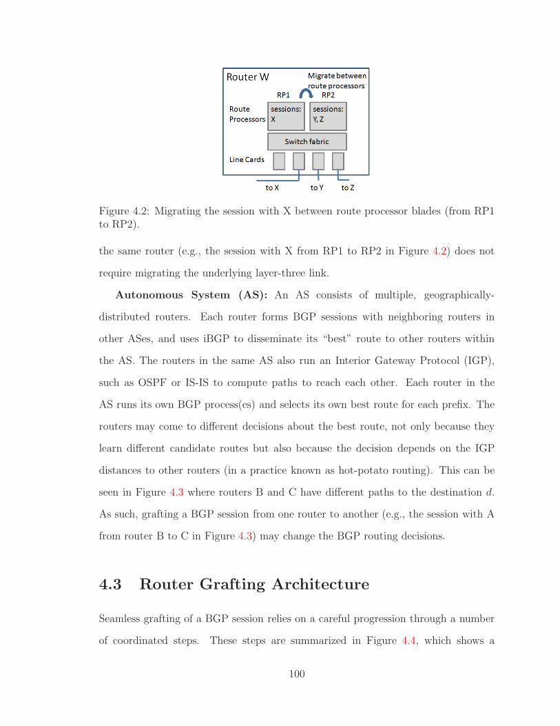
Figure 4.2: Migrating the session with X between route processor blades (from RP1to RP2).
the same router (e.g., the session with X from RP1 to RP2 in Figure 4.2) does not
require migrating the underlying layer-three link.
Autonomous System (AS): An AS consists of multiple, geographically-
distributed routers. Each router forms BGP sessions with neighboring routers in
other ASes, and uses iBGP to disseminate its “best” route to other routers within
the AS. The routers in the same AS also run an Interior Gateway Protocol (IGP),
such as OSPF or IS-IS to compute paths to reach each other. Each router in the
AS runs its own BGP process(es) and selects its own best route for each prefix. The
routers may come to different decisions about the best route, not only because they
learn different candidate routes but also because the decision depends on the IGP
distances to other routers (in a practice known as hot-potato routing). This can be
seen in Figure 4.3 where routers B and C have different paths to the destination d.
As such, grafting a BGP session from one router to another (e.g., the session with A
from router B to C in Figure 4.3) may change the BGP routing decisions.
4.3 Router Grafting Architecture
Seamless grafting of a BGP session relies on a careful progression through a number
of coordinated steps. These steps are summarized in Figure 4.4, which shows a
100

Figure 4.3: Migrating session with A between routers (from B to C).
migrate-from router that hands off one of its BGP sessions to a migrate-to router in
the same AS. These routers do not need to run the same software or be from the
same vendor—they need only have the added support for router grafting. When the
grafting process starts, the migrate-from router is responsible for handling a BGP
session with the remote end-point router A (not shown). This BGP session with
router A is to be migrated. The migrate-from router begins exporting the routing
information and the migrate-to router is initialized with its own session-level data
structures and a copy of the policy configuration, without actually establishing the
session (Figure 4.4(a)). Then, the TCP connection is migrated, followed by the
underlying link (Figure 4.4(b)). Finally, the migrate-to router imports the routing
state and updates the other routers (Figure 4.4(c)), resulting in the migrate-to router
handling the BGP session with the remote end-point ((Figure 4.4(d)). This section
focuses exclusively on control-plane operations, deferring discussion of the data plane
until Section 4.4.
4.3.1 Copying BGP Session Configuration
Each BGP session end-point has a variety of configuration state needed to establish
the session with the remote end-point (with a given IP address and AS number)
and apply policies for filtering and modifying route announcements. The network
101

(a) Pre-config, Export RIB. (b) Migrate link and TCP.
(c) Import RIB. (d) After migration.Figure 4.4: Router grafting mechanisms – migrating a session with Router A (not shown)from router Migrate-from to router Migrate-to. The boxes marked bgpd and network stackare the software programs. The boxes marked RIBA, configA, and TCPA are the routing,configuration, and TCP state respectively.
operators, or an automated management system, configure the session end-point by
applying configuration commands at the router’s command-line interface or uploading
a new configuration file. The router stores the configuration information in various
internal data structures.
Rather than exporting these internal data structures, we capitalize on the fact that
the current configuration is captured in a well-defined format in the configuration file.
Our design simply “dumps” the configuration file for the migrate-from router, extracts
the commands relevant to the BGP session end-point, and applies these commands to
102

the migrate-to router, after appropriate translation to account for vendor-dependent
differences in the command syntax. This allows the migrate-to router to create its
own internal data structures for the configuration information.
However, the migrate-to router is not yet ready to assume responsibility for the
BGP session. To finish initializing the migrate-to router, we extend the BGP state
machine to include an ‘inactive’ state, where the router can create data structures
and import state for the session without attempting to communicate with the remote
end-point. The migrate-to router transitions from the ‘inactive’ state to ‘established’
state when instructed by the grafting process.
4.3.2 Exporting & Resetting Run-Time State
A router maintains a variety of state for BGP session end-points. To meet our goals,
BGP grafting need only consider the Routing Information Bases (RIBs)—the other
state may be simply reinitialized at the migrate-to router2.
Routing Information Bases (RIBs): The most important state associated
with the BGP session-end-point is stored in the routing information bases—the Adj-
RIB-in and Adj-RIB-out. In our architecture, we dump the RIBs at the migrate-from
router to prepare for importing the information at the migrate-to router. While the
RIBs are represented differently on different router platforms, the information they
store is standardized as part of the BGP protocol. In most router implementations,
the RIB data structure is factored apart from the rest of the routing software, and
many routers support commands for “dumping” the current RIBs. Even though
the RIB dump formats vary by vendor, de facto standards like the popular MRT
format [10] do exist.
2Router grafting does not preclude the remaining state from being included, simply we chosenot to in order to keep code modifications at a minimum while still meeting our goals of (i) routingprotocol adjacencies staying up and (ii) all routing protocol messages being received.
103
State in the BGP state machine: A BGP session end-point stores information
about the BGP state machine. We can forgo migrating this state – the BGP session
is either ‘established’ or not. If the session is in one of the not-established states,
we can simply close the session at the migrate-from router and start the migrate-to
router in the idle state. This does not trigger any transient disruption—since the
session is not “up” anyway. If the session at the migrate-from router is ‘established,’
we can start the new session at the migrate-to router in the ‘inactive’ state.
BGP timers: BGP implementations also include a variety of timers, many of
which are vendor-dependent. For example, some routers use an MRAI (Minimum
Route Advertisement Interval) timer to pace the transmission of BGP update mes-
sages. This is purely a local operation at one end-point of the session, not requiring
any agreement with the remote end-point. Another common timer is the keep-alive
interval that drives the periodic sending of heartbeat messages, and a hold timer for
detecting missing keep-alive messages from the remote end-point. Fortunately, miss-
ing a single keep-alive message, or sending the message slightly early or late, would
not erroneously detect a session failure because routers typically wait for three missed
keep-alive messages before tearing down the session. As such, we do not migrate BGP
timer values and instead simply initialize whatever timers are used at the migrate-to
router.
BGP statistics: BGP implementations maintain numerous statistics about each
session and even individual routes. These statistics, while broadly useful for network
monitoring, are not essential to the correct operation of the router. They only have
meaning at the local session end-point. In addition, these statistics are vendor de-
pendent and not well modularized in the router software implementations. As such,
we do not migrate these statistics and instead allow the migrate-to router to initialize
its own statistics as if it were establishing a new session.
104

4.3.3 Migrating TCP Connection & IP Link
As part of BGP session grafting, the TCP connection must move from the migrate-
from router to the migrate-to router. Because we do not assume any support from
the remote end-point, the migrate-to router must use the same IP addresses and
sequence and acknowledgment numbers that the migrate-from router was using. In
BGP, IP addresses are used to uniquely identify the BGP session end-points and not
the router as a whole. Further, we assume the link between the remote end-point
and the migrate-from (or migrate-to) router is a single hop IP network where the IP
address is not used for reachability, but only for identification. As such, the session
end-point can easily retain its address (and sequence and acknowledgment numbers)
when it moves. That is, the single IP address identifying the migrating session can be
disassociated from the migrate-from router and associated with the migrate-to router.
Our architecture simply migrates the local state associated with the TCP connection
from one router to another.
As with any TCP migration technique, the network must endure a brief period
of time when neither router is responsible for the TCP connection. TCP has its own
retransmission mechanism that ensures that the remote end-point retransmits any
unacknowledged data. As long as the transient outage is short, the TCP connection
(and, hence, the BGP session) remains up. TCP implementations tolerate a period of
at least 100 seconds [24] without receiving an acknowledgment—significantly longer
than the migration times we anticipate. The amount of TCP state is relatively small,
and the two routers are close to one another, leading to extremely fast TCP migration
times.
The underlying link should be migrated (e.g., by changing the path in the underly-
ing programmable transport network) close to the same time as the TCP connection
state, to minimize the transient disruption in connectivity. Still, the network may
need to tolerate a brief period of inconsistency where (say) the TCP connection
105

state has moved to the migrate-to router while the traffic still flows via the migrate-
from router. During this period, we need to prevent the migrate-from router from
erroneously responding to TCP packets with a TCP RST packet that resets the con-
nection. This is easily prevented by configuring the migrate-from router’s interface
to drop TCP packets sent to the BGP port (i.e., 179). The migrate-from route can
successfully deliver regular data traffic received during the transmission, as discussed
later in Section 4.4.
4.3.4 Importing BGP Routing State
Once link and connection migration are complete, the migrate-to router can move its
end-point of the BGP session from the ‘inactive’ state to the ‘established’ state. At
this time, the migrate-to router can begin “importing” the RIBs received from the
migrate-from router. However, the import process is not as simple as merely loading
the RIB entries into its own internal data structures. The migrate-from and migrate-
to routers could easily have a different view of the “best” route for each destination
prefix, as illustrated in Figure 4.5. In this scenario, before the migration, A reaches
E’s prefixes over the direct link between them, and B reaches E’s prefixes via A; after
the migration, A should reach E’s prefixes via B, and B should reach E’s prefixes
over the direct link. Similarly, suppose routers C and D connect to a common prefix.
Before the migration, E follows the AS path “100 200 300” (through C) to reach that
prefix; after the migration E follows the AS path “100 200 400” (through D). Reaching
these conclusions requires routers A and B to rerun the BGP decision process based
on the new routes, and disseminate any routing changes to neighboring routers.
To make the process transparent to the remote end-point, we essentially emulate
starting up a new session at router B, with router A temporarily playing the role of
the remote end-point to announce the routes learned from E. This requires router A
to replay the Adj-RIB-in state associated with E to router B. Router B stores these
106

Figure 4.5: A topology where AS 200 has migrate-from router A, migrate-to routerB, internal router F, and external routers C, D, and G, and remote end-point E.
routes and reruns its BGP decision process, as necessary, to compute the new best
routes to prefixes E is announcing. This will cause update messages to be sent to
other routers within the AS and, sometimes, to external routers (like C and D). If the
attributes of the route (e.g., the AS-PATH) do not change, as is the case in Figure 4.5,
other ASes like AS 300 and AS 400 do not receive any BGP update message (since,
from their point of view, the route has not changed), thus minimizing the overhead
that router grafting imposes on the global BGP routing system.
Next, we update E with the best routes selected by B. Here, we take advantage
of the fact that E has already learned routes from the migrate-from router A. The
change in topology might change some of those routes, and we need to account for
that. To do so, the migrate-to router runs the BGP decision process to compare
its currently-selected best route to the route learned from the migrate-from router.
If the best route changes, B sends an update message to its neighbors, including
router E. This is in fact exactly the same operation the router would perform upon
receiving a route update from any of its neighbors. We expect that routers A and B
would typically have the same best route for most prefixes, especially if A and B are
relatively close to each other in the IGP topology. As such, most of the time router B
107

would not change its best route and hence would not need to send an update message
to router E.
4.4 Correct Routing and Forwarding
Router grafting cannot be allowed to compromise the correct functioning of the net-
work. In this section, we discuss how grafting preserves correct routing state (in the
control plane) and correct packet forwarding (in the data plane), even when unex-
pected routing changes occur in the middle of the grafting process.
4.4.1 Control Plane: BGP Routing State
Routing changes can, and do, happen at any time. BGP routers easily receive millions
of update messages a day, and these could arrive at any time during the grafting
process – while the migrate-from router dumps its routing state, while the TCP
connection and underlying link are migrated, or while the migrate-to router imports
the routing state and updates its routing decisions. Our grafting solution can correctly
handle BGP messages sent at any of these times.
While the migrate-from router dumps the BGP routing state: The goal
is to have the in-memory Routing Information Base (RIB) be consistent with the RIB
that was dumped as part of migration. Here, we take advantage of the fact that the
dumping process and the BGP protocol work on a per-prefix basis. Consider a Adj-
RIB-in with three routes (p1, p2, p3) corresponding to three prefixes, of which (p1
and p2) have been dumped already. When an update p3’ (for the same prefix as p3) is
received, the in-memory RIB can be updated since it corresponds to a prefix that has
not been dumped, – to prevent dumping a prefix while it is being updated, the single
entry in the RIB needs to be locked. If we receive an update p1’ (for the same prefix
as p1), processing it and updating the in-memory RIB without updating the dumped
108

image will cause the two to be inconsistent – delaying processing the update is an
option, but that would delay convergence as well. To solve this, we capitalize on BGP
being an incremental protocol where any new update message implicitly withdraws
the old one. Since we treat the dumped RIB as a sequence of update messages, we
can process the update immediately and append p1’ to the end of the dumped RIB
to keep it consistent.
While the TCP connection and link are migrating: BGP update messages
may be sent while the TCP connection and the underlying link are migrating. If a
message is sent by the remote end-point, the message is not delivered and is correctly
retransmitted after the link and TCP connection come up at the migrate-to router.
If an update message is sent by another router to the migrate-from router over a
different BGP session, there is not a problem because the migrate-from router is no
longer responsible for the recently-rehomed BGP session. Therefore, the migrate-from
router can safely continue to receive, select, and send routes. If an update message
is sent by another router to the migrate-to router over a different BGP session, the
migrate-to router can install the route in its Adj-RIB-in for that session and, if needed,
update its selection of the best route – similar to when a route is received before the
migration process.
While the migrate-to router imports the routing state: The final case to
consider is when the migrate-to router receives a BGP update message while import-
ing the routing state for the rehomed session. Whether from the remote end-point
or another router, if the route is for a prefix that was already imported, there is no
problem since the migration of that prefix is complete. If it is for a prefix that has not
already been imported, only messages from the remote end-point router need special
care. (BGP is an asynchronous protocol that does not depend on the relative order of
processing for messages learned from different neighbors.) A message from the remote
end-point must be processed after the imported route but we would like to process
109

it immediately. Since the update implicitly withdraws the previous announcement
(which is in the dump image), we mark the RIB entry to indicate that it is more
recent than the dump image. This way, we can skip importing any entries in the
dump image which have a more recent RIB update.
4.4.2 Data Plane: Packet Forwarding
Thus far, this paper has focused on the operation of the BGP control plane. However,
the control plane’s only real purpose is to select paths for forwarding data packets.
Fortunately, grafting has relatively little data-plane impact. When moving a BGP
session between blades in the same router, the underlying link does not move and
the “best” routes do not change. As such, the forwarding table does not change, and
data packets travel as they did before grafting took place – the data traffic continues
to flow uninterrupted.
The situation is more challenging when grafting a BGP session from one router to
another, where these two routers do not have the same BGP routing information and
do not necessarily make the same decisions. Because the TCP connection and link
are migrated before the migrate-to router imports the routing state, the remote end-
point briefly forwards packets through the migrate-to router based on BGP routes
learned from the migrate-from router. Since BGP route dissemination within the
AS (typically implemented using iBGP) ensures that each router learns at least one
route for each destination prefix, the two routers will learn routes for the same set
of destinations. Therefore, the undesirable situation where the remote end-point
forwards packets that the migrate-to router cannot handle will not occur.
Although data packets are forwarded correctly, the end-to-end forwarding path
may temporarily differ from the control-plane messages. For example, in Figure 4.5,
data packets sent by E will start traversing the path through AS 400, while E’s
control plane still thinks the AS path goes through AS 300. These kinds of temporary
110

Figure 4.6: The router grafting prototype system.
inconsistencies are a normal occurrence during the BGP route-convergence process,
and do not disrupt the flow of traffic. Once the migrate-to router finishes importing
the routes, the remote end-point will learn the new best route and control- and data-
plane paths will agree again.
Correct handling of data traffic must also consider the packets routed toward
the remote end-point. During the grafting process, routers throughout the AS for-
ward these packets to the migrate-from router until they learn about the routing
change (i.e., the new egress point for reaching these destinations). Since the migrate-
from router knows where the link, TCP connection, and BGP session have moved, it
can direct packets in flight there through temporary tunnels established between the
migrate-from router and the migrate-to router.
4.5 BGP Grafting Prototype
We have developed an initial prototype to demonstrate router grafting. Figure 4.6 de-
picts the main components of the prototype. These include (i) a modified Quagga [6]
routing software, (ii) the graft daemon for controlling the entire process, (iii) the
SockMi [21] kernel module for TCP migration, and (iv) a Click [72] based data plane
for implementing link migration.
111

The controlling entity in the prototype is the graft daemon. This is the entity that
initiates the BGP session grafting, interacting with each of the other components to
perform the necessary steps. We assume each graft daemon can be reached by an
IP address. With this, the graft daemon on the migrate-from router will initiate a
TCP connection with the daemon on the migrate-to router. Once established, the
migration process follows the six general steps discussed in the following subsections.
4.5.1 Configuring the Migrate-To Router
In our architecture, configuration state is gleaned from a dump of the migrate-from
router’s configuration file, rather than its internal data structures. The graft daemon
first extracts BGP session configuration from the configuration file of the migrate-from
router, including the rules for filtering and modifying route announcements. Then the
extracted configuration commands are applied to the migrate-to router. Our current
implementation includes a simplistic parser for Quagga’s commands for configuring
BGP sessions3. In order to configure the migrate-to router before migrating the TCP
connection, we added an ‘inactive’ state to the BGP state machine. We also added a
configuration command to the Quagga command-line interface:
neighbor w.x.y.z inactive
that triggers the router to create all internal data structures for the session, without
attempting to open or accept a socket with the remote end-point.
4.5.2 Exporting Migrate-From BGP State
Once the migrate-to router is configured, the grafting process can proceed to the
second step, which is initiating the export of the routing state on the migrate-from
3As we add support for XORP, we will develop a more complete parser as the configuration willrequire translating between configuration languages—generally a hard problem, though easier in ourcase because we focus on a relatively narrow aspect of the configuration.
112

router. The grafting daemon on the migrate-from router initiates the export process
by calling a command in Quagga that we added:
neighbor w.x.y.z migrate out
When this command is executed, our modified Quagga software traverses the internal
data structures, dumping the necessary routing state (Adj-RIB-in and the selected
routes in the loc-RIB) to a file.
4.5.3 Exporting Migrate-From TCP State
Once the routing state is dumped, the modified Quagga calls the export socket
function as part of the SockMi API to migrate the TCP state. This function makes
an ioctl call to the kernel module, passing the socket’s file descriptor. The SockMi
kernel module is a Linux kernel module for kernels 2.4 through 2.6—we tested with
kernel version 2.6.19.7. The ioctl call causes the kernel module to interact with
Linux’s internal data structures. It removes the TCP connection from the kernel,
writing the socket state to a character device. Note that part of this state is related
to the protocol itself (e.g., the current sequence number) as well as the buffers (e.g.,
the receive queue and the transmit queue of packets sent, but not acknowledged).
When this state is written, the kernel module sends a signal to the graft daemon on
the migrate-from router, which can read from the character device and send to the
daemon on the migrate-to router.
4.5.4 Importing the TCP State
The next step is to initiate the import of the TCP state at the migrate-to router.
Upon receiving the state from the migrate-from router, the graft daemon on the
migrate-to router first notifies Quagga that it is about to import state for a given
‘inactive’ session. This is done through a command we added:
113

neighbor w.x.y.z migrate in
Upon executing the command, our modified Quagga invokes the import socket func-
tion in the SockMi API. This function blocks until a TCP connection is imported.
During this time, the graft daemon makes an ioctl to the SockMi kernel module. The
graft daemon then passes the TCP session state to a character device which is read
by the kernel module. The SockMi kernel module accesses the Linux data structures
to add a socket with that TCP connection state, which unblocks the import socket
function.
4.5.5 Migrating the Layer-Three Link
At this point, the graft daemon of the migrate-to router triggers the migration of the
underlying link. This includes removing the migrating session’s IP address from the
migrate-from router, adding the IP address to the migrate-to router, and migrating
the layer-two link. As we did not have access to equipment to use a programmable
transport network, we instead built our own simple layer-two network that connects
both the migrate-from and migrate-to router to the remote end-point with a Click [72]
configuration that emulates a ‘programmable transport’. This Click configuration
performs a simple switching primitive that connects the remote end-point to either
the migrate-from or the migrate-to router. In one setting, packets from the migrate-
from router are sent to the remote end-point router, packets from the migrate-to
router are dropped, and packets from the remote end-point router are sent to the
migrate-from router. With the alternative setting, the reverse occurs, forming a link
between the migrate-to router and the remote-end point router. This switch value
is settable via a handler, making it accessible to the graft daemon running on the
migrate-from router.
114

4.5.6 Importing Routing State
As the final step, when the importing of the TCP connection is complete and the
import socket function is unblocked, the modified Quagga reads the routing state,
which was stored in a file when the local graft daemon read it in from the graft
daemon running on the migrate-from router. Much as the “normal” operation of
the router, which receives a BGP message from a socket and then calls a function to
handle the update, the importing process will read the Adj-RIB-in from a file and call
the same function to process the routing update. For comparing the RIB from the
migrate-from router to the migrate-to router, the importing process reads the route
from the file, looks up the route in the local RIB, and compares them. If they differ,
it will use existing functions to send out the route to the peer.
4.6 Optimizations for Reducing Impact
Grafting a BGP session requires incrementally updating the remote end-point as
well as the other routers in the AS. In this section, we present optimizations that can
further reduce the traffic and processing load imposed on routers not directly involved
in the grafting process. These optimizations capitalize on the knowledge that grafting
is taking place and the routers’ local copy of the routes previously learned from the
remote end-point. First, we discuss how we can keep routers from sending unnecessary
updates to their eBGP neighbors. Second, we then discuss how the majority of iBGP
messages can be eliminated. Finally, we consider the intra-cluster router case where
the routes do not change.
4.6.1 Reducing Impact on eBGP Sessions
Importing routes on the migrate-to router, and withdrawing routes on the migrate-
from router, may trigger a flurry of update messages to other BGP neighbors. Con-
115
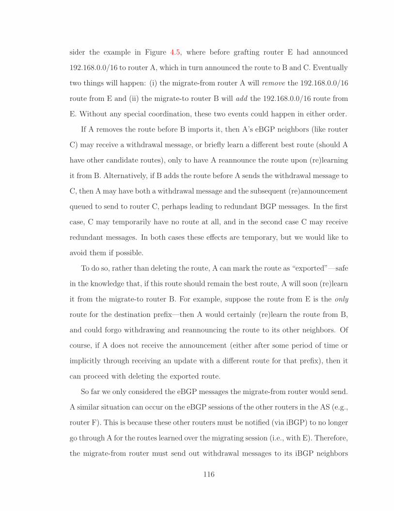
sider the example in Figure 4.5, where before grafting router E had announced
192.168.0.0/16 to router A, which in turn announced the route to B and C. Eventually
two things will happen: (i) the migrate-from router A will remove the 192.168.0.0/16
route from E and (ii) the migrate-to router B will add the 192.168.0.0/16 route from
E. Without any special coordination, these two events could happen in either order.
If A removes the route before B imports it, then A’s eBGP neighbors (like router
C) may receive a withdrawal message, or briefly learn a different best route (should A
have other candidate routes), only to have A reannounce the route upon (re)learning
it from B. Alternatively, if B adds the route before A sends the withdrawal message to
C, then A may have both a withdrawal message and the subsequent (re)announcement
queued to send to router C, perhaps leading to redundant BGP messages. In the first
case, C may temporarily have no route at all, and in the second case C may receive
redundant messages. In both cases these effects are temporary, but we would like to
avoid them if possible.
To do so, rather than deleting the route, A can mark the route as “exported”—safe
in the knowledge that, if this route should remain the best route, A will soon (re)learn
it from the migrate-to router B. For example, suppose the route from E is the only
route for the destination prefix—then A would certainly (re)learn the route from B,
and could forgo withdrawing and reannouncing the route to its other neighbors. Of
course, if A does not receive the announcement (either after some period of time or
implicitly through receiving an update with a different route for that prefix), then it
can proceed with deleting the exported route.
So far we only considered the eBGP messages the migrate-from router would send.
A similar situation can occur on the eBGP sessions of the other routers in the AS (e.g.,
router F). This is because these other routers must be notified (via iBGP) to no longer
go through A for the routes learned over the migrating session (i.e., with E). Therefore,
the migrate-from router must send out withdrawal messages to its iBGP neighbors
116

and the migrate-to router must send out announcements to its iBGP neighbors. This
may result in the other routers in the AS (e.g., router F) temporarily withdrawing
a route, temporarily sending a different best route, or sending a redundant update
to their eBGP neighbors. Because of this, we have the migrate-from router send the
marked list to each of its iBGP neighbors and a notification that these all migrated
to the migrate-to router – this list is simply the list of prefixes, not the associated
attributes. We expect this list to be relatively small in terms of total bytes. With
this list, the other routers in the AS can perform the same procedure, and eliminate
any unnecessary external messages.
4.6.2 Reducing Impact on iBGP Sessions
While using iBGP unmodified is sufficient for dealing with the change in topology
brought about by migration, it is still desirable to reduce the impact migration has
on the iBGP sessions. Here, since the route-selection policy will likely be consistent
throughout an ISP’s network, we can reduce the number of update messages sent by
extending iBGP (an easier task than modifying eBGP). When the migrate-from and
migrate-to routers select the same routes, the act of migration will not change the
decision. Since all routers are informed of the migration, the iBGP updates can be
suppressed (the migrate-from router withdrawing the route and the migrate-to router
announcing the route). When the migrate-from and migrate-to routers select different
routes, it is most likely due to differences in IGP distances. For the migrate-to router,
the act of migration will cause all routes learned from the remote end-point router to
become directly learned routes, as opposed to some distance away, and therefore the
migrate-to router will now prefer those routes (except when the migrate-to router’s
currently selected route is also directly learned). This change in route selection causes
the migrate-to router to send updates to its iBGP neighbors notifying them of the
change. However, since it is more common to change routes, we can reduce the number
117

of updates that need to be sent with a modification to iBGP where updates are sent
when the migrate-to router keeps a route instead of when it changes a route. Other
routers will be notified of the migration and will assume the routes being migrated
will be selected unless told otherwise.
4.6.3 Eliminating Processing Entirely
Re-running the route-selection processes is essential as migration can change the
topology, and therefore change the best route. When migrating within a cluster
router, the topology does not change, and therefore we should be able to eliminate
processing entirely. The selected best route will be a consistent selection on every
blade. Therefore, even when migrating, while the internal data structures might need
to be adjusted, no decision process needs to be run and no external messages need to
be sent. In fact, there is no need for any internal messages to be sent either. With
the modified iBGP used for communication between route processor blades, the next
hop field is the next router, not the next processor blade – i.e., iBGP messages are
only used to exchange routes learned externally and do not affect how packets are
forwarded internally. Therefore, upon migration, there is no need to send an update
as the routes learned externally have already been exchanged.
While exchanging messages and running the decision process can be eliminated,
transferring the routing state from the exporting blade to the importing blade is still
needed. Being the blade responsible for a particular BGP session requires that the
local RIB have all of the routes learned over that session. While some may have been
previously announced by the migrate-from blade, not all of them were. Therefore,
we need to send over the Adj-RIB-in for the migrating session in order to know all
routes learned over that session as well as which subset of routes the migrate-from
blade announced were associated with that session.
118

4.7 Performance Evaluation
In this section, we evaluate router grafting through experiments with our proto-
type system and realistic traces of BGP update messages. We focus primarily on
control-plane overhead, since data-plane performance depends primarily on the la-
tency for link migration—where our solution simply leverages recent innovations in
programmable transport networks. First, we evaluate our prototype implementation
from Section 4.5 to measure the grafting time and CPU utilization on the migrate-
from and migrate-to routers. Then we evaluate the effectiveness of our optimizations
from Section 4.6 in reducing the number of update messages received by other routers.
4.7.1 Grafting Delay and Overhead
The first experiment measures the impact of BGP session grafting on the migrate-
from and migrate-to routers. To do this we supplemented the topology shown in
Figure 4.5 with a router adjacent to E (in a different AS) and a router adjacent to
B (in a different AS). These two extra routers were fed a BGP update message trace
taken from RouteViews [7]. This essentially fills the RIB of B and E with routes that
have the same set of prefixes, but different paths. We used Emulab [105] to run the
experiment on servers with 3GHz processors and 2GB RAM.4
The time it takes to complete the migration process is a function of the size of the
routing table. The larger it is, the larger the state that needs to be transferred and
the more routes that need to be compared. To capture this relationship, we varied
the RIB size by replaying multiple traces. The results, shown in Figure 4.7, include
both the case where migration occurs between routers (when the migrate-to router
must run the BGP decision process) and the case where migration is between blades
(where the decision process does not need to run because the underlying topology
4This is roughly comparable to the route processors used in commercially available high-endrouters.
119

Figure 4.7: BGP session grafting time vs. RIB size.
is not changed). The “between blades” curve, then, illustrates the time required to
transfer the BGP routes and import them into the internal data structures. Note
that these results do not imply that TCP needs to be able to handle this long of
an outage where packets go unacknowledged – the TCP migration process takes less
than a millisecond. Instead, when compared to rehoming a customer today, where
there is downtime measured in minutes, the migration time is small. In fact, since
in our setup AS100 and AS200 have a peering agreement, the actual migration time
would be less if AS100 were a customer of AS200 (since AS100 would announce fewer
routes to AS200).
The CPU utilization during the grafting process is also important. The BGP
process on the migrate-from router experienced only a negligible increase in CPU
utilization for dumping the BGP RIBs. The migrate-to router needs to import the
routing entries and compare routing tables. For each prefix in the received routing
information, the migrate-to router must perform a lookup to find the routing table
entry for that prefix. Figure 4.8 shows the CPU utilization at 0.2 second intervals,
as reported by top, for the case where the RIB consists of 200,000 prefixes. There
are three things to note. First, the CPU utilization is roughly constant. This is
perhaps due to the implementation where the data is received, placed in a file, then
120

Figure 4.8: The CPU utilization at the migrate-to router during migration, with a200k prefix RIB.
iteratively read from the file and processed before reading the next. This keeps the
CPU utilization at only a fraction as computation is mixed with reads from disk.
Second, the CPU utilization is the same for both migrating between routers and
migrating between blades. The case between routers merely takes longer because of
the additional work involved in running the BGP decision process. Third, migration
can be run as a lower priority task and use less CPU but take longer – preventing
the migration from effecting the performance of the router during spikes in routing
updates, which commonly results in intense CPU usage during the spikes.
4.7.2 Optimizations for Reducing Impact
While the impact on the migrate-from and migrate-to routers is important, perhaps
a more important metric is the impact on the routers not involved in the migration,
including other routers within the same AS as well as the eBGP neighbors. If the
overhead of grafting is relatively contained, network operators could more freely apply
the technique to simplify network-management tasks.
First and foremost, the remote end-point experiences an overhead directly pro-
portional to the number of additional BGP update messages it receives. The number
of messages depends on how many best routes differ between the migrate-from and
121

(a) Without optimization. (b) Reducing eBGP impact. (c) Reducing iBGP impact.
Figure 4.9: Updates sent as a result of migration.
migrate-to router—the migrate-from router must send an update message for every
route that differs. The exact amount depends heavily on the proximity of the migrate-
from and migrate-to routers—if the two routers are in the same Point-of-Presence of
the ISP, perhaps no routes would change. As such, we do not expect this overhead to
be significant. Since the sources of overhead for the remote end-point are relatively
well understood, and it is difficult to acquire the kinds of intra-ISP measurement data
necessary to quantify the number of route changes, we do not present a plot for this
case.
Perhaps the more significant impact is on the other routers, both within the AS
and in other ASes, that may have to learn new routes for the prefixes announced by
the remote end-point. To evaluate this, we measured the number of updates that
would be sent as a function of the fraction of prefixes where the migrate-from router
had selected a different route than the migrate-to router. By doing so, this covers the
entire range of migration targets (i.e. it does not limit our evaluation to migration
within a PoP). Recall that this difference is what needs to be corrected. Also recall
that the prefixes being considered here are the ones learned from the router at the
remote end-point of the session being migrated, not the entire routing table, as these
are the routes that could impact what is sent to other routers. For our measurement,
we use a fixed set of 100,000 prefixes. However, the results are directly proportional
to the number of prefixes, and can therefore be scaled appropriately – for migrating
122

a customer link, the number of prefixes would be significantly smaller, for migrating
a peering link, the number of prefixes could be higher.
The results are shown in Figure 4.9, with the three graphs representing the three
different cases as discussed in Section 4.6: (a) direct approach with no optimizations,
(b) optimizations to reduce eBGP messages by capitalizing on redundant information
in the network, and (c) optimizations to reduce iBGP messages by treating the route
selection changing as the common case. For the graphs, each line represents a fixed
fraction of differing routes that change the selected route as a result of the grafting.
For example, consider where the migrate-from router selects a particular route differ-
ent than the migrate-to router. In this case, after migration, the migrate-to router
selects the route the migrate-from selected (i.e., it changes its own route). Each line
represents the fraction of times this change occurs—for example, the line labeled 0.2
in Figure 4.9 is where 20% of the routes that differ will change to the routes selected
by the migrate-from router.
There are several things of note from the graphs. First is that the direct (un-
optimized) approach must send significantly more messages. In the case where the
selected routes do not differ much, which we consider will be a most likely scenario,
the optimized approaches hardly send any messages at all. Second, when comparing
Figure 4.9(b) with Figure 4.9(c), we can see that depending on what would be con-
sidered the common case, we can choose a method that would result in the fewest
updates. For (b), the assumption is that when the routes differ, the migrate-to router
will not change to the routes the migrate-from selected. Whereas in (c), the assump-
tion is that when the routes differ, the migrate-from router will change to the routes
the migrate-from router selected. The reason they would change is that the routes
learned from the remote end-point of the session being migrated will now be directly
learned routes, rather than via iBGP. It is likely that the policy of route selection is
consistent throughout the ISPs network, and therefore differences will be due to IGP
123
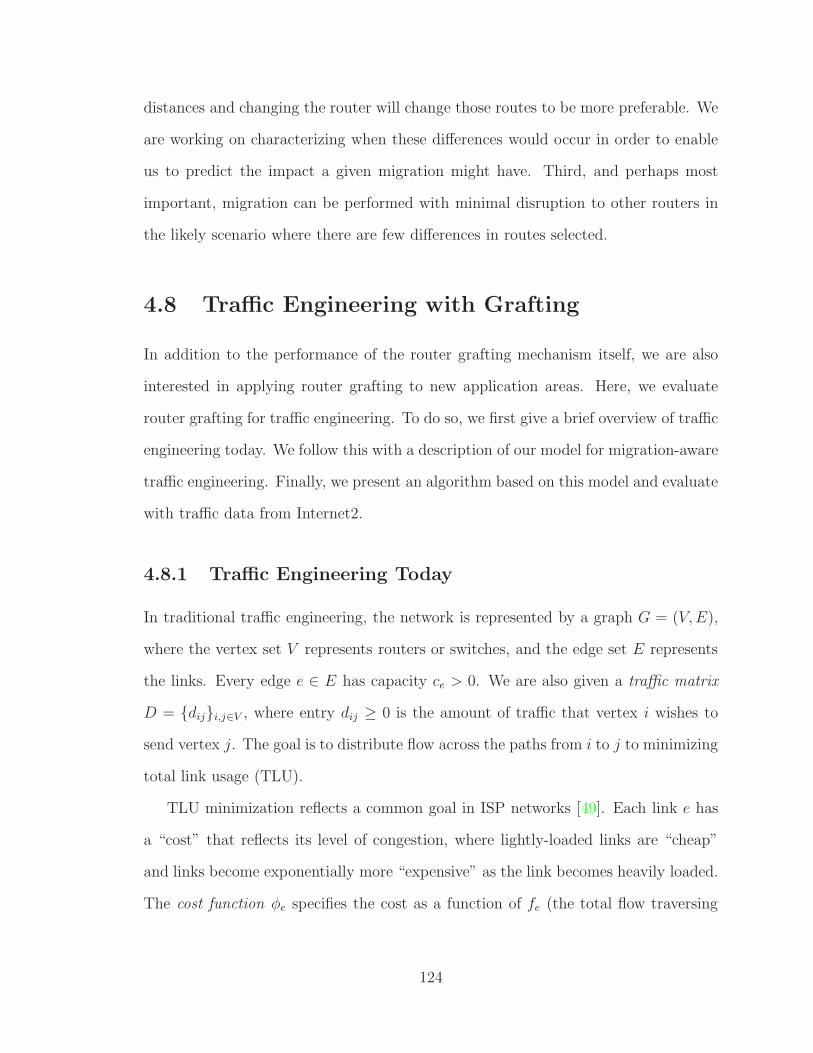
distances and changing the router will change those routes to be more preferable. We
are working on characterizing when these differences would occur in order to enable
us to predict the impact a given migration might have. Third, and perhaps most
important, migration can be performed with minimal disruption to other routers in
the likely scenario where there are few differences in routes selected.
4.8 Traffic Engineering with Grafting
In addition to the performance of the router grafting mechanism itself, we are also
interested in applying router grafting to new application areas. Here, we evaluate
router grafting for traffic engineering. To do so, we first give a brief overview of traffic
engineering today. We follow this with a description of our model for migration-aware
traffic engineering. Finally, we present an algorithm based on this model and evaluate
with traffic data from Internet2.
4.8.1 Traffic Engineering Today
In traditional traffic engineering, the network is represented by a graph G = (V,E),
where the vertex set V represents routers or switches, and the edge set E represents
the links. Every edge e ∈ E has capacity ce > 0. We are also given a traffic matrix
D = {dij}i,j∈V , where entry dij ≥ 0 is the amount of traffic that vertex i wishes to
send vertex j. The goal is to distribute flow across the paths from i to j to minimizing
total link usage (TLU).
TLU minimization reflects a common goal in ISP networks [49]. Each link e has
a “cost” that reflects its level of congestion, where lightly-loaded links are “cheap”
and links become exponentially more “expensive” as the link becomes heavily loaded.
The cost function φe specifies the cost as a function of fe (the total flow traversing
124

the edge) and ce (the edge capacity). Every φe is a piecewise linear, strictly increasing
and convex function.
We use the cost function from [49], shown below:
φe(fe, ce) =
fe 0 ≤ fece
< 1
3
3fe −2
3ce
1
3≤ fe
ce< 2
3
10fe −16
3ce
2
3≤ fe
ce< 9
10
70fe −178
3ce
9
10≤ fe
ce< 1
500fe −1468
3ce 1 ≤ fe
ce< 11
10
5000fe −16318
3ce
11
10≤ fe
ce< ∞
The goal is to distribute the entire demand between every pair of vertices in
a manner that minimizes the sum of all link costs (i.e., Σe∈E φ(fe, ce)). (Observe
that the flow along an edge can exceed the edge’s capacity.) TLU minimization can
be formulated as minimum-cost multicommodity flow and is thus computable using
existing algorithms for computing multicommodity flows. Realizing this objective in
practice can be done via MPLS and a management system that solves the optimization
problem and installs the resulting paths. Network operators often take the indirect
approach of tuning Interior Gateway Protocol (IGP) weights to closely approximate
the optimal distribution of the traffic [49].
4.8.2 Migration-Aware Traffic Engineering
We now extend the traffic-engineering model in Section 4.8.1 to incorporate migration.
Table 4.1 summarizes the notation.
Distinguishing users from network nodes: In our model for traffic engineering
with migration, the network (see Figure 4.10) is represented by a graph G = (V,E),
where the vertex set V is the union of two disjoint subsets, U and N . U is the set
125

Figure 4.10: Network model for traffic engineering with migration.
Notation DescriptionG Network graph G = (V,E)V Network vertex, union of U and NE Network edge, union of EU and EN
U Set of network usersN Set of network nodesEU Subset of edges that connect user u ∈ U to net-
work nodes in N , EU ⊆ U ×NEN Subset of edges that connect network node n ∈ N
to network nodes in N , EN ⊆ N ×Nce capacity of edge e ∈ ELu Potential links, Lu ⊆ EU
D Demand matrix, D = {dij}i,j∈Udij Amount of traffic that user i wishes to send user
jφe cost function used in TLU minimization, function
of fe/cefe Total flow traversing the edge e
Table 4.1: Summary of notation used in model of traffic engineering with migration.
126

of network users, that is, originators and receivers of traffic, and N is the the set of
network nodes, that is, the routers/switches in the network. The term “users” here
refers to users of the network and not to end-users. In an ISP network, the set of
users U represents routers in neighboring networks (“adjacent routers”) and the set
of network nodes N represents the routers in the ISP’s internal network (“internal
routers”).
User edges are potential links: To capture the ability to migrate, we introduce
the notion of potential links that represent the locations where the user can possibly
connect to the network. The edge set E is the union of two disjoint subsets, EU and
EN , where EU ⊆ U × N is the subset of edges connecting users to network nodes,
and EN ⊆ N ×N is the subset of edges connecting network nodes to other network
nodes. Each edge e ∈ EN has capacity ce ≥ 0, which measures the amount of flow
that can traverse edge e. We impose no capacity constraints on the edges in EU (that
is, these edges have infinite capacity). We call the set of all edges Lu ⊆ EU that
connect user u ∈ U to network nodes in N “the set of u’s potential links” (that is,
∀u ∈ U , Lu = {e = (u, v)| e ∈ EU}).
In ISP networks, the set of potential links Lu for each adjacent router (user) u
represents the points at which u can connect to the ISP network. This can, in practice,
depend on the underlying transport network that can, for example, limit a user to
connecting only to network nodes in nearby geographical regions. In addition, the
set of potential links can reflect latency considerations, e.g., it is beneficial to home
frequently-communicating users near each other.
Demand matrix is user-to-user: Our model distinguishes network users from
network nodes, and our demand matrix captures this distinction; we are now given
a demand matrix D = {dij}i,j∈U , where each entry dij specifies the amount of traffic
user i wishes to send user j.
127

Each user must use a single potential link: The high-level goal is, for every pair
of users i and j such that dij > 0, to distribute flow from i to j between the routes
from i to j in G, subject to the constraint that every user can only connect to the
network via a single link. That is, for every user u ∈ U , traffic flowing from that
user to the other users, and vice versa, can only traverse a single edge in Lu; traffic
along all other edges in Lu must be 0. When optimizing the flow of traffic through
the network we can again consider the TLU minimization objective.
4.8.3 Practical Considerations
Naturally, our formal framework does not capture all the constraints that could arise
in practice. We now present several such constraints and discuss how these can
be incorporated into our model. We leave these as interesting directions for future
research.
Cost of migration. Our framework does not model the cost of migration (in terms
of processing, offline time, and more) yet this is expected to be a consideration in
practice (we present some indication of the impact of this cost, based on experiments
with Internet2 data, in Section 4.8.8). We can incorporate that cost into our model
as follows. The input will include, in addition to the other components, an edge
eu ∈ Lu, for every user u ∈ U , that represents the link that user u is currently using
to connect to the network, and also costs associated with changing each user u’s
current connection edge to other edges in Lu.
Router limitations. Other practical considerations are the physical limitations of
the individual vertices in the network, including the number of links that each vertex
can support, and also the capacity of the node (in terms of processing, memory, band-
width, etc.). This can be incorporated into our model through additional constraints
128

(e.g., limits on the number of incoming links per node, node-capacity functions de-
pendent on incoming traffic amount, etc.).
Multi-homed users. We did not model the case that users are multi-homed, that is,
that users connect to the network at more than one location. This alters our constraint
that a single potential link must be chosen per user. To incorporate this into our
model we can introduce a variable for each user u that specifies how many links in
Lu that user is allowed to send/receive traffic along. It also adds the complexity that
changing the ingress point may alter the egress point (i.e., “hot-potato routing” [97]),
thus changing the traffic matrix beyond the change introduced with migration. The
design and evaluation of heuristics/algorithms for this more general environment is
left for future work.
4.8.4 The Max-Link Heuristic
Determining which edge links to migrate requires new algorithms that complement
traditional traffic engineering algorithms. We present a simple heuristic, that we
term the “max-link heuristic”, which uses a multicommodity flow solution to guide
the choice of a potential link for each user (which determines which edge links need
to migrate).
The max-link heuristic first computes the multicommodity flow in the input net-
work that contains all potential links. Then, the heuristic uses this “fully fractional”
flow (where users’ traffic can be split between all of their potential links) to choose a
single potential link for each user, thus constructing a feasible (“integral”) solution.
To do this, the max-link heuristic discards, for every user u ∈ U , all potential links in
Lu but the single potential link which carries the most traffic in the multicommodity
flow solution (breaking ties arbitrarily).
The max-link heuristic consists of these three steps:
129

• Step I: Compute multicommodity flow f in the input network G (that con-
tains all potential links for each user) for the given demand matrix D. That is,
compute the minimum-cost multicommodity flow for TLU minimization with-
out restricting users to sending and receiving traffic along a single potential
link. The multicommodity flow solution f tells us how much traffic every user
u sends and receives along each of the potential links in Lu. We let t(lu) denote
the sum of traffic that user u sends and receives along the potential link lu ∈ Lu.
• Step II: Use the most utilized potential link. Choose, for every user
u ∈ U , a potential link for which t(lu) is maximized. (Migrate users’ currently
connected link to the chosen potential link if necessary.)
• Step III: Compute the multicommodity flow in the resulting network,
that is, in the network obtained through the removal from G of all potential
links but those chosen above. The max-link heuristic outputs (1) the choice of a
single potential link for each user and (2) the optimal routing of traffic subject
to these migration decisions.
4.8.5 Experimental Results on Internet2
We now present our experimental evaluation of the max-link heuristic. The goal of
this evaluation is to demonstrate the benefits of using migration in traffic engineering,
even with a simple heuristic. We first show in Section 4.8.6 that our max-link heuristic
does indeed lead to an improvement in network performance. We then examine two
additional concerns relating to more practical questions – how often do links need to
be migrated (Section 4.8.7) and how many links need to be migrated (Section 4.8.8).
130

We based all of our experiments on data collected from Internet2 [60], which
consists of N = 9 core routers and U = 205 external routers5. We collected one week
of data starting January 18, 2010. From each router, we downloaded the previously
collected NetFlow data which provides summaries of the sampled flows (at the rate
of 1/100 packets) in 5-minute intervals (1-week of traffic is 2016 5-minute samples).
We also downloaded the routing information base (RIB) and the output for the ‘show
bgp neighbor ’ command, both of which are captured every two hours. Every NetFlow
entry contains the incoming interface, which we used to represent an external source
user. We used the routing tables for each of the routers to determine the egress
router for each flow, along with the specific interface on the egress router that the
flow exits the network on, which we used to represent the external destination user.
This enabled us to generate an external-user-to-external-user traffic matrix.
4.8.6 Migration Improves Network Utilization
The first metric of importance is simply the improvement that can be obtained when
utilizing link migration. Our results for a single 5-minute period appears in Fig-
ure 4.14. This particular interval was chosen as it represents the average perfor-
mance, which we discuss later in this subsection. The Figure shows results for the
original (optimally engineered) network (the “original topology” line), and for traffic
engineering with migration with 2 links per user (the “optimized topology” line)6.
Our choice of the set of potential links (the Lu’s) in the experiments was based on
geographical distance, with the users’ locations inferred from which router they are
connected to in the original topology – e.g., some users connected in Chicago would
5Determined from examining BGP information as well as traffic traces – in reality, we may havebeen missed an externally connected router or we may have included a router that is not externallyconnected.
6We do not present results for more potential links per-user, as in our small topology almostevery two users end up connected to a common network node when there are many potential links,and thus traffic between these users does not traverse the network at all. To elaborate, considerthe extreme case in which all users have potential links to all routers. Here, a multicommodity flowsolution will give no guidance on which links to use since no traffic will even traverse the network.
131
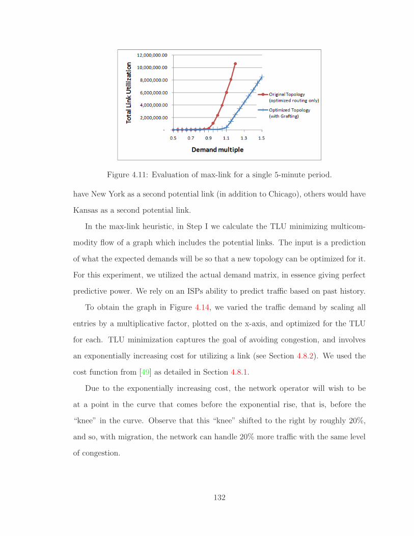
Figure 4.11: Evaluation of max-link for a single 5-minute period.
have New York as a second potential link (in addition to Chicago), others would have
Kansas as a second potential link.
In the max-link heuristic, in Step I we calculate the TLU minimizing multicom-
modity flow of a graph which includes the potential links. The input is a prediction
of what the expected demands will be so that a new topology can be optimized for it.
For this experiment, we utilized the actual demand matrix, in essence giving perfect
predictive power. We rely on an ISPs ability to predict traffic based on past history.
To obtain the graph in Figure 4.14, we varied the traffic demand by scaling all
entries by a multiplicative factor, plotted on the x-axis, and optimized for the TLU
for each. TLU minimization captures the goal of avoiding congestion, and involves
an exponentially increasing cost for utilizing a link (see Section 4.8.2). We used the
cost function from [49] as detailed in Section 4.8.1.
Due to the exponentially increasing cost, the network operator will wish to be
at a point in the curve that comes before the exponential rise, that is, before the
“knee” in the curve. Observe that this “knee” shifted to the right by roughly 20%,
and so, with migration, the network can handle 20% more traffic with the same level
of congestion.
132

As mentioned, the particular 5-minute interval was chosen as it represents the
average case performance. To expand on this, we present in Figure 4.12 and Figure
4.13 the results for all 2016 5-minute intervals. In Figure 4.12, we show a time-series
representation where each data point represents the improvement achieved with link
migration. We define this improvement metric as the amount of traffic the network
can carry in the optimized topology at the same level of congestion as the original
topology – where the TLU represents the level of congestion. So, from the original
topology, we found the minimal TLU with a demand multiple of 1 (e.g., the actual
amount of traffic). We then determined which demand multiple in the optimized
topology (i.e., with migration) would result in the same TLU. In other words, in terms
of the graph in Figure 4.11, we found the y value for x=1 on the original topology
line, and used that y value to find the x value on the optimized topology line. Plotted
in Figure 4.13 is a cumulative distribution function of the same information.
From this we can see on average, traffic engineering with migration can increase
network utilization by about 18.8%. Intuitively this comes from two factors. The first
is that by optimizing the homing locating based on the demand matrix, users that
communicate will tend to get closer together. Without link migration, the homing
location must be determined up front and then cannot change. With link migration,
we can alter the topology to bring users that communicate a lot closer together.
The second factor is that by re-optimizing the topology, we can have a significant
impact on congested links. By giving some traffic the ability to avoid the congested
link (through migration), we can reduce the congestion on that link. There are,
however, a small number of cases (2.6%) where migrating links actually decreased
performance. Being a simple heuristic, there are no worst case guarantees with our
max-link heuristic, and so it is expected that there can be conditions which result in
poor performance.
133

Figure 4.12: Evaluation of max-link over 7 days of traffic – time-series.
Figure 4.13: Evaluation of max-link over 7 days of traffic – cumulative distributionfunction.
4.8.7 Frequent Migration is Not Necessary
In Section 4.8.6, we examined the benefits of utilizing link migration in traffic engi-
neering. We looked at the benefits when we could migrate every interval and knew
the traffic in the next interval. However, predicting this can be difficult on that short
of a time scale. Here, we examine how frequent we really need to be migrating.
To determine how frequent migration should occur, we looked at different periods
– every 5 minutes, 30 minutes, 1 hour, 6 hours, 12 hours, 24 hours. We utilized a
prediction of the average demand matrix for the next interval (e.g., the next 6 hours)
when computing the multicommodity flow as per Step I in the max-link heuristic.
This was used to determine the optimized topology that would be used for the entire
134

interval min max mean #worse (frac.)
5 mins 0.783 1.55 1.188 54 (0.0267)30 mins 0.757 1.55 1.166 146 (0.0724)1 hour 0.777 1.55 1.163 152 (0.0753)6 hours 0.801 1.55 1.149 182 (0.0902)12 hours 0.856 1.55 1.141 191 (0.0947)24 hours 0.806 1.55 1.083 465 (0.2306)
Table 4.2: Comparison of the improvement over the original topology optimized forrouting only when performing grafting at different intervals (over 7 days traffic).
interval. We determined the TLU for each 5-minutes of traffic using this topology
and compared the results to the original topology.
Shown in Table 4.2, are the results for the different intervals – showing the data
point with the worst performance, the best performance (capped at 1.55 due to run
time of the experiment), the average performance, and the number (and fraction) of
data points which were worse. As could be expected, the longer the interval, the
worse the results. However, even re-optimizing the topology every 6 or 12 hours
still has good performance. Not only does utilizing longer intervals cut down on any
overhead of the migration itself (including calculating what to migrate), but it also
has the advantage that as the intervals become longer, traffic patterns smooth out
and become more predictable.
4.8.8 Only a Fraction of Links Need to be Migrated
Our formulation of traffic engineering with migration does not currently incorporate
the cost of migration, yet this is expected to be a consideration in practice. To decide
which users to migrate, we can weigh the cost of migrating a user against the gain
from migrating that user; when the impact of migrating a user is low (e.g., when
that user generates and consumes negligible amounts of traffic), migration might be
undesirable.
135

Figure 4.14: Fraction of traffic each user node sends in an example 5-minute period.
To investigate this, we plotted in Figure 4.14 the amount of traffic each user
sends or receives for an example 5-minute interval. On the x-axis is the index of the
user, sorted by the amount of traffic they generate/consume. On the y-axis is the
cumulative fraction of the total traffic. We placed markers on each user for which our
max-link heuristic determined should be migrated.
From this we can see that 85% of the traffic comes from the first 42 users, of
which, max-link only determined 5 of them to be migrated. Hence, we can still
obtain a significant improvement in network performance while migrating only a
small number of links.
To evaluate this effect across the entire data sample, we plot the cumulative dis-
tribution functions of the number of links that need to be migrated considering three
different thresholds – 100% (i.e., migrate all links that max-link determined need to
be migrated), 95%, and 90%. As can be seen, by not worrying about a small fraction
of traffic (which only minimally affect the actual network utilization), we can greatly
reduce the number of links that need to be migrated.
136

Figure 4.15: Cumulative distribution function of the number of links that need to bemigrated during each interval over 7 days of traffic (2016 5-minute intervals). Shownare three lines corresponding to different thresholds – only links in the top X% oftraffic are migrated.
4.9 Related Work
High availability and ease of network management are goals of many systems, and
therefore router grafting has much in common with them. In particular, ones that
attempt to minimize disruptions during planned maintenance. One possibility is to
reconfigure the routing protocols such that traffic will no longer be sent to the router
about to undergo maintenance [98, 52]. Alternatively, others have decoupled the
control plane and data plane such that the router can continue to forward packets
while the control plane goes off-line (e.g., rebooted) [93, 32]. However, unlike router
grafting, these require modifications to the remote end-point router and they are only
useful for temporarily shutting down the session on a given physical router, rather
than enabling the session to come back up on a different router as in router grafting.
In this regard, router grafting shares more in common with VROOM (as discussed
in Chapter 3), which makes use of virtual machine migration to ease network man-
agement. Maintenance could be performed without taking down the router simply
137

by migrating the virtual router to another physical router. This requires the two
physical routers to be compatible (running the same virtualization technology), a
limitation router grafting does not have. In fact, router grafting does not rely on
virtual machine technology. Kozuch showed the ability to migrate without the use of
virtualization [73], but did so at the granularity of the entire operating system and all
running processes. With a coarse granularity, the physical router where the virtual
router is being migrated to must be able to handle the entire virtual router’s load.
Router grafting is also similar to the RouterFarm work [14], which targeted re-
homing a customer. However, it required restarting the session and is more disruptive
than router grafting. Along similar lines, high-availability routers enable switching
over to a different router or blade in a router [3]. This, however, is done either
through periodically check-pointing, which preserves the memory image, or running
two complete instances of the router software concurrently, which is an inefficient use
of resources.
While we presented router grafting in the context of a BGP session, we envision
it being more general. Along these lines, partitioning the prefix space across multiple
routers or blades is a possibility.ViAggre [19] partitions the prefix space across multi-
ple routers, however it is a static architecture not one which dynamically repartitions
the prefix space as router grafting could.
Finally, we made use of TCP socket migration to handle change or disruption in
end-points. One alternative is to modify the TCP protocol to include the ability to
change IP addresses [94]. Since the IP address of the end-points in router grafting
can remain the same, we do not need this capability, but could make use of it.
In terms of our application of router grafting to traffic traffic engineer-
ing, there has been much work on schemes for traffic engineering in ISP net-
works [101][63][43][18][109]. This work interprets traffic engineering as the adaptation
138

of the routing of traffic within the network so as to optimize performance. We, in
contrast, also explore how to adapt traffic’s ingress and egress points.
Changes to the traffic matrix can also result from actions of the users themselves
(e.g., using overlay routing to route around congested areas, as in Detour [92] and
RON [17]). However, such “selfish” overlay routing can, as pointed out in [82], signif-
icantly reduce the effectiveness of traffic engineering (as it lies outside the control of
the ISP network operator). Interestingly, as these overlays shift the traffic, migration
could be used to better handle the traffic within the ISPs network.
Migration in the ISP context has received but little attention. Mechanisms for
the re-home of customers have been introduced [14], but the implications for traffic
engineering has not been studied.
4.10 Summary
Router grafting is a new technique that opens many new possibilities for managing
a network. It does this by enabling, without disruption, the migration of a routing
session between (i) physical routers, (ii) blades in a cluster router, and (iii) routers
from different vendors. We were able to do this while being transparent to the remote
end-point. We handled the changes in topology through incremental updates, only
sending out the necessary updates to convey the difference. Importantly, we did
not affect the correctness of the network as the data plane will continue to forward
packets and routing updates do not cause the migration to be aborted. Through the
development of new algorithms and evaluation with real traffic, we demonstrated the
applicability of router grafting to traffic engineering. Not only can router grafting
simplify existing network management tasks, but it can also enable new applications.
139

Chapter 5
Conclusion
The Internet is becoming a more integral part of people’s daily life – a trend that
will undoubtedly continue into the future. In order to run the underlying infrastruc-
ture, network operators continuously need to make changes to the network – e.g.,
add routers, change policies, and manage available resources such as bandwidth. Un-
fortunately, these changes causes disruption. In this dissertation we take a novel
approach to addressing this disruption by refactoring the router software to better
accommodate change. In this chapter we present a summary of the contributions in
Section 5.1. We then present a unified architecture which combines the three systems
presented in this dissertation in Section 5.2. We discuss some directions for future
work in Section 5.3 and wrap up with some concluding remarks in Section 5.4.
5.1 Summary of Contributions
This dissertation proposes a refactoring of router software in order to provide a more
reliable network.
First, we tailored software and data diversity (SDD) to the unique properties of
routing protocols, so as to avoid buggy behavior at run time. Our bug-tolerant router
executes multiple diverse instances of routing software, and uses voting to determine
140

the output to publish to the forwarding table, or to advertise to neighbors. We
designed and implemented a router hypervisor that makes this parallelism transparent
to other routers, handles fault detection and booting of new router instances, and
performs voting in the presence of routing-protocol dynamics, without needing to
modify software of the diverse instances. Experiments with BGP message traces and
open-source software running on our Linux-based router hypervisor demonstrated
that our solution scales to large networks and efficiently masks buggy behavior.
Second, we argued that breaking the tight coupling between the physical and
logical configurations of a network can provide a single, general abstraction that
simplifies network management. Specifically, we proposed VROOM (Virtual ROuters
On the Move), a new network-management primitive where virtual routers can move
freely from one physical router to another. We presented the design, implementation,
and evaluation of novel migration techniques for virtual routers with either hardware
or software data planes. Our evaluation showed that VROOM is transparent to
routing protocols and results in no performance impact on the data traffic when a
hardware-based data plane is used.
Finally, we introduced the concept of router grafting, and realize an instance of
it through BGP session migration. This capability allows an operator to rehome a
customer with no disruption, compared to downtimes today measured in minutes.
We demonstrated that BGP session migration can be performed in today’s mono-
lithic routing software, without much modification or refactoring of the code. We
also demonstrated that with our architecture, BGP session migration can be per-
formed (i) transparently, where the remote BGP session end-point is not modified
and is unaware migration is happening, (ii) with minimal impact on other routers
not directly involved in the migration, and (iii) such that unplanned routing changes
(such as link failures) during the grafting process do not affect correctness, and where
packets are delivered successfully even during the migration. We additionally applied
141

router grafting to traffic engineering where not only can network operators control
how traffic flows through the network, but now can also control where traffic enters
and exits the network. We developed a new algorithm to determine what links to mi-
grate and through an evaluation using real traffic traces from Internet2 showed that
significant improvements in the utilization of the network can be achieved through
router grafting.
A commonality among each of our solutions is that rather than solving a problem
on top of the existing system, we changed the system to make the problem go away
fundamentally. With the bug-tolerant router, rather than test, debug, and analyze
router software to reduce bugs, we changed the platform to tolerate the bugs. With
VROOM, rather than extend protocols and management practice to minimize disrup-
tion, we utilized virtualization in the routers to decouple the logical IP-layer topology
from the physical topology. With router grafting, rather than extend protocols, or be
forced to settle for coarse-grain migration, we made individual routing sessions mi-
gratable. With our application of router grafting to traffic engineering, rather than
focusing on optimization of routing on a fixed traffic matrix, we utilized a mechanism
which enables us to change the traffic matrix.
Collectively, by taking a unique approach, the contributions of this dissertation
enable network operators to perform the desired change on their network without (i)
possibly triggering bugs in routers that causes Internet-wide instability, (ii) causing
unnecessary network re-convergence events, (iii) having to coordinate with neigh-
boring network operators, or (iv) needing an Internet-wide upgrade to new routing
protocols.
142
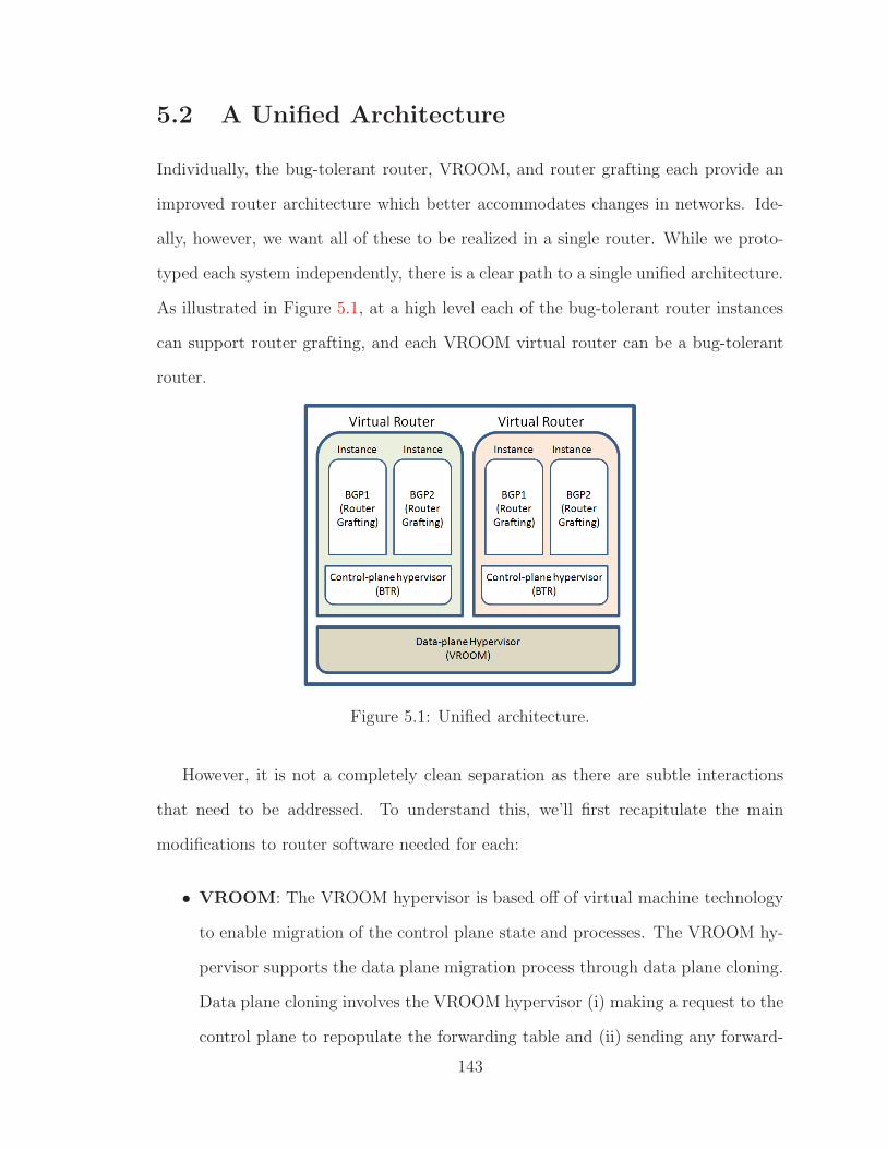
5.2 A Unified Architecture
Individually, the bug-tolerant router, VROOM, and router grafting each provide an
improved router architecture which better accommodates changes in networks. Ide-
ally, however, we want all of these to be realized in a single router. While we proto-
typed each system independently, there is a clear path to a single unified architecture.
As illustrated in Figure 5.1, at a high level each of the bug-tolerant router instances
can support router grafting, and each VROOM virtual router can be a bug-tolerant
router.
Figure 5.1: Unified architecture.
However, it is not a completely clean separation as there are subtle interactions
that need to be addressed. To understand this, we’ll first recapitulate the main
modifications to router software needed for each:
• VROOM: The VROOM hypervisor is based off of virtual machine technology
to enable migration of the control plane state and processes. The VROOM hy-
pervisor supports the data plane migration process through data plane cloning.
Data plane cloning involves the VROOM hypervisor (i) making a request to the
control plane to repopulate the forwarding table and (ii) sending any forward-
143

ing table updates to both the local forwarding table and the remote forwarding
table.
• BTR: The BTR hypervisor allows multiple processes to run simultaneously
and virtualizes their interface at the socket level, but does not provide complete
platform virtualization. The BTR hypervisor (i) intercepts input messages and
multicasts them to each instance, (ii) intercepts output messages and performs
voting on them before sending out the update, and (iii) manages router instances
with the ability to bootstrap new instances and kill buggy instances.
• Router grafting: Router grafting requires modifications to the router soft-
ware to enable the importing and exporting of state, and re-running decision
processes based on the new state. Router grafting also requires operating sys-
tem functionality in order to support the importing and exporting of the state
for individual TCP sessions.
From this, we can see that each of the possible interactions requires some modifi-
cation in order to provide a complete, unified system:
• VROOM ↔ BTR: VROOM needs to be able to make a request to the virtual
router to repopulate the forwarding table. This is an interface we had to add
to the routing software and therefore the BTR hypervisor needs to present
this interface. The routing software will still need this interface, and will use
the modifications we made originally to enable VROOM. The BTR hypervisor
could then simply forward the request from the VROOM hypervisor to each of
the router instances. They would each repopulate the forwarding table, which
would trigger the BTR hypervisor to vote on each entry before writing the result
to the forwarding table.
• VROOM ↔ Router grafting: Router grafting needs modifications to the
operating system to be able to import/export all of the TCP session state that
144

is associated with a given socket. The operating system that is providing the
socket interface to the routing software processes will need to have this capa-
bility. In a container based virtualization solution (e.g., OpenVZ), as we used
in our VROOM prototype, the virtual router does not have its own operating
system – it shares one with all of the other virtual routers. In a platform vir-
tualization solution (e.g., Xen, KVM, VMWare), the virtual routers will each
have their own operating system.
• BTR ↔ Router grafting: With router grafting, the router software also had
modifications to be able to import and export a socket. In the bug-tolerant
router, the routing software actually has sockets that provide a communication
channel to the BTR hypervisor and the BTR hypervisor has the sockets that
provide a communication channel to neighboring routers. The routing software
would not need to change as the communication channel to the BTR hypervisor
was hidden from the routing software. The BTR hypervisor would need the
ability to import and export a socket, and in turn, trigger an import or export
in each of the instances. In addition to importing and exporting a socket, with
router grafting the routing session state is also imported and exported along
with re-running decision processes based on the updated state. With the bug-
tolerant router, there are multiple instances. Therefore, the BTR hypervisor
would need to export the state from each instance at the migrate-from router,
vote on that state, and then at the migrate-to router import that state in each
of the instances. The process will still be transparent to neighboring routers,
but as is the case with a bug-tolerant router, with multiple instances there will
be more processing to perform a session migration.
145

5.3 Future Work
In addition to building the unified architecture, each individual system has directions
for future research. Here, we examine a few of these.
5.3.1 Monitoring in Addition to Voting for a Bug-Tolerant
Router
With the bug-tolerant router we perform voting among multiple instances of routing
software performing the same functionality to detect and correct any bugs. A buggy
instance of the software can be rebooted or replaced. A complementary approach
would be to utilize techniques which perform anomaly detection on the run-time
characteristics of the software itself [96] – e.g., memory utilization, CPU utilization,
latency. By detecting something is going wrong (e.g., CPU utilization is spiking
without a flood of updates to process) we may be able to catch buggy instances
before they become faulty. This proactive correction of instances will lead to a more
reliable system.
5.3.2 Hosted and Shared Network Infrastructure with
VROOM
In the world of computing, a shift has begun towards the use of infrastructures which
are hosted and shared (i.e., cloud computing). This has increased the level of innova-
tion by enabling companies to come out with new web services for less cost, created
new business models where a party can lease out slices of servers on demand with a
pay-per-use model, and even simplified management in private (non-hosted) networks
by enabling a company to more easily run independent services on its own servers.
We believe that the same will be true of networking where many applications would
146
greatly benefit from in-network functionality beyond the basic connectivity offering
of today.
A key challenge that these infrastructures present is that they decouple the owner
of the infrastructure from the service provider that is running the routing protocols
and applications. Not only would planned maintenance be disruptive, as in networks
today, but techniques which lessen the impact (e.g., diverting traffic away) are no
longer possible since these are two different parties. VROOM provides a solution
here as it decouples physical from logical, so physical maintenance can be done with-
out impacting logical. Isolation is also important, which has been examined in the
computing context [66], as well as the virtual router context [22]. We view a router
as more than just routing protocols, so both will be relevant.
5.3.3 Router Grafting for Security
Router grafting is a mechanism to seamlessly move links and the associated BGP
session. This not only aids in today’s network management, it enables new applica-
tions. We applied router grafting to traffic engineering, but there may be other novel
uses of the technology that are worth exploring. One promising application area is
to use router grafting as part of a “moving-target” defense mechanism [53]. Static
systems allow attackers to observe the operation of the system over long periods of
time and plan attacks with confidence. With a moving-target defense, the system is
continuously changed so that the planned attack will no longer work. By utilizing
router grafting, we can continuously change the topology and change which router
(different vendors, different models) a particular neighboring network is connected to.
147

5.4 Concluding Remarks
The Internet is becoming critical infrastructure. As such, we need a network infras-
tructure that we can depend on. We took an approach which does not require an
Internet-wide upgrade, yet improved the reliability of the network. By rethinking the
design of routers, we enable network operators to manage their networks without trig-
gering much of the disruption that is seen today when performing this management.
We utilized software and data diversity to build a router which operates correctly
even in the inevitable presence of bugs. We introduced novel migration mechanism,
both at the granularity of a virtual router and at the level of an individual link and
associated routing session. Not only does this migration simplify today’s management
tasks, it also enables new applications as well.
Perhaps most importantly, we have shown that significant improvements can be
made without having to wipe the slate clean in the Internet. We do this by capital-
izing on recent trends in networks and routers to rethink the router design to better
accommodate the changes network operators routinely need to make. We believe
that our work is an important step towards a more reliable Internet and provide a
novel approach to challenges faced in network management. Finally, this work raises
interesting questions about what exactly a router is, and the various ways routers can
be “sliced and diced.” We plan to explore these questions in our ongoing work.
148

Bibliography
[1] BIRD Internet routing daemon. http://bird.network.cz/.
[2] Cisco 7200 simulator. (software to run Cisco IOS images on desktop PCs) www.ipflow.utc.fr/index.php/Cisco_7200_Simulator.
[3] Cisco IOS high availability curbs downtime with faster reloads andupgrades. http://www.cisco.com/en/US/products/ps6550/prod_white_
papers_list.html.
[4] Olive. (software to run Juniper OS images on desktop PCs) juniper.cluepon.net/index.php/Olive.
[5] OpenVZ. http://www.openvz.org.
[6] Quagga software routing suite. http://www.quagga.net.
[7] Route views project. www.routeviews.org.
[8] Vyatta (open-source router vendor). www.vyatta.com.
[9] XORP: Open Source IP Router. http://www.xorp.org.
[10] IETF draft: MRT routing information export format, July 2009. http://
tools.ietf.org/id/draft-ietf-grow-mrt-10.txt.
[11] The Internet2 Network. http://www.internet2.edu/.
[12] T. Afferton, R. Doverspike, C. Kalmanek, and K. K. Ramakrishnan. Packet-aware transport for metro networks. IEEE Communication Magazine, March2004.
[13] S. Agarwal, C. Chuah, S. Bhattacharyya, and C. Diot. Impact of BGP dynamicson router CPU utilization. In Passive and Active Measurement, April 2004.
[14] Mukesh Agrawal, Susan Bailey, Albert Greenberg, Jorge Pastor, PanagiotisSebos, Srinivasan Seshan, Jacobus van der Merwe, and Jennifer Yates. Router-Farm: Towards a dynamic, manageable network edge. In ACM SIGCOMMWorkshop on Internet Network Management (INM), September 2006.
149
[15] C. Alaettinoglu, V. Jacobson, and H. Yu. Towards millisecond IGP convergence.In IETF Draft, November 2000.
[16] R. Alimi, Y. Wang, and Y. R. Yang. Shadow configuration as a network man-agement primitive. In SIGCOMM, August 2008.
[17] David G. Andersen, Hari Balakrishnan, M. Frans Kaashoek, and Robert Morris.Resilient overlay networks. In Proc. ACM SOSP, October 2001.
[18] D. Applegate, L. Breslau, and E. Cohen. Coping with network failures: Routingstrategies for optimal demand oblivious restoration. In Proc. ACM SIGCMET-RICS, June 2004.
[19] Hitesh Ballani, Paul Francis, Tuan Cao, and Jia Wang. Making Routers LastLonger with ViAggre. In Proc. of USENIX Symposium on Networked SystemsDesign and Implementation, April 2009.
[20] E. Berger and B. Zorn. DieHard: Probabilistic memory safety for unsafe lan-guages. In Programming Languages Design and Implementation, June 2006.
[21] Massimo Bernaschi, Francesco Casadei, and Paolo Tassotti. SockMi: a solutionfor migrating TCP/IP connections. In Proc. Euromicro International Confer-ence on Parallel, Distributed and Network-Based Processing, 2007.
[22] Sapan Bhatia, Murtaza Motiwala, Wolfgang Muhlbauer, Yogesh Mundada, Vy-tautas Valancius, Andy Bavier, Nick Feamster, Larry Peterson, and JenniferRexford. Trellis: A platform for building flexible, fast virtual networks on com-modity hardware. In Proc. Workshop on Real Overlays and Distributed Systems(ROADS), December 2008.
[23] Olivier Bonaventure, Clarence Filsfils, and Pierre Francois. Achieving sub-50 milliseconds recovery upon BGP peering link failures. IEEE/ACM Trans.Networking, October 2007.
[24] Robert Braden. Requirements for Internet Hosts - Communication Layers. RFC1122, October 1989.
[25] B. Brenner. Cisco IOS flaw prompts symantec to raise threat level. In Infor-mation Security Magazine, Sept. 2005.
[26] S. Bryant and P. Pate. Pseudo wire emulation edge-to-edge (PWE3) architec-ture. RFC 3985, March 2005.
[27] J. Caballero, T. Kampouris, D. Song, and J. Wang. Would diversity reallyincrease the robustness of the routing infrastructure against software defects?In NDSS, Feb. 2008.
[28] M. Caesar, D. Caldwell, N. Feamster, J. Rexford, A. Shaikh, and K. van derMerwe. Design and implementation of a routing control platform. In NSDI,April 2005.
150

[29] M. Caesar and J. Rexford. Building bug-tolerant routers with virtualization.In PRESTO, August 2008.
[30] M. Castro and B. Liskov. Practical byzantine fault tolerance. In OSDI, February1999.
[31] Joe Chabarek, Joel Sommers, Paul Barford, Cristian Estan, David Tsiang,and Steve Wright. Power awareness in network design and routing. In IEEEINFOCOM, 2008.
[32] E. Chen, R. Fernando, J. Scudder, and Y. Rekhter. Graceful Restart Mechanismfor BGP. RFC 4724, January 2007.
[33] B-G. Chun, P. Maniatis, and S. Shenker. Diverse replication for single-machinebyzantine-fault tolerance. In USENIX Annual Technical Conference, June 2008.
[34] Ciena CoreDirector Switch. http://www.ciena.com.
[35] Cisco ASR 1000 series aggregation services router high availability: Deliv-ering carrier-class services to midrange router. http://www.cisco.com/en/
US/prod/collateral/routers/ps9343/solution_overview_c22-450809_
ps9343_Product_Solution_Overview.html.
[36] MPLS VPN Carrier Supporting Carrier. http://www.cisco.com/en/US/docs/ios/12_0st/12_0st14/feature/guide/csc.html.
[37] Cisco Logical Routers. http://www.cisco.com/en/US/docs/ios_xr_sw/
iosxr_r3.2/interfaces/command/reference/hr32lr.html.
[38] Christopher Clark, Keir Fraser, Steven Hand, Jacob Gorm Hansen, Eric Jul,Christian Limpach, Ian Pratt, and Andrew Warfield. Live Migration of VirtualMachines. In NSDI, May 2005.
[39] B. Cox, D. Evans, A. Filip, J. Rowanhill, W. Hu, J. Davidson, J. Knight,A. Nguyen-Tuong, and J. Hiser. N-variant systems: A secretless framework forsecurity through diversity. In Usenix Security, August 2006.
[40] Brendan Cully, Geoffrey Lefebvre, Dutch Meyer, Mike Feeley, Norm Hutchin-son, and Andrew Warfield. Remus: High availability via asynchronous virtualmachine replication. In NSDI, April 2008.
[41] D-ITG. http://www.grid.unina.it/software/ITG/.
[42] J. Duffy. BGP bug bites Juniper software. In Network World, December 2007.
[43] A. Elwalid, C. Jin, S. Low, and I. Widjaja. MATE: MPLS adaptive trafficengineering. In Proc. IEEE INFOCOM, 2001.
[44] Emulab. http://www.emulab.net.
151

[45] J. Evers. Trio of Cisco flaws may threaten networks. In CNET News, January2007.
[46] N. Feamster and H. Balakrishnan. Detecting BGP configuration faults withstatic analysis. In NSDI, May 2005.
[47] N. Feamster and J. Rexford. Network-wide prediction of BGP routes. InIEEE/ACM Trans. Networking, April 2007.
[48] Nick Feamster, Lixin Gao, and Jennifer Rexford. How to lease the Internetin your spare time. ACM SIGCOMM Computer Communications Review, Jan2007.
[49] Bernard Fortz and Mikkel Thorup. Internet traffic engineering by optimizingOSPF weights. In Proc. IEEE INFOCOM, 2000.
[50] Pierre Francois and Olivier Bonaventure. Avoiding transient loops during theconvergence of link-state routing protocols. IEEE/ACM Transactions on Net-working, 15(6):1280–1932, December 2007.
[51] Pierre Francois, Pierre-Alain Coste, Bruno Decraene, and Olivier Bonaventure.Avoiding disruptions during maintenance operations on BGP sessions. IEEETransactions on Network and Service Management, 4(3):1–11, 2007.
[52] Pierre Francois, Mike Shand, and Olivier Bonaventure. Disruption-free topologyreconfiguration in OSPF networks. In IEEE INFOCOM, May 2007.
[53] Anup K. Ghosh, Dimitrios Pendarakis, and William H. Sanders. National cyberleap year summit 2009 co-chairs report: Moving target defense. http://www.
qinetiq-na.com/Collateral/Documents/English-US/InTheNews_docs/
National_Cyber_Leap_Year_Summit_2009_Co-Chairs_Report.pdf.
[54] Joel Gottlieb, Albert Greenberg, Jennifer Rexford, and Jia Wang. Automatedprovisioning of BGP customers. IEEE Network Magazine, November/December2003.
[55] Timothy G. Griffin and Joao Luıs Sobrinho. Metarouting. In SIGCOMM,August 2005.
[56] D. Gupta, S. Lee, M. Vrable, S. Savage, A. Snoeren, A. Vahdat, G. Varghese,and G. Voelker. Difference engine: Harnessing memory redundancy in virtualmachines. In OSDI, December 2008.
[57] Maruti Gupta and Suresh Singh. Greening of the Internet. In SIGCOMM,August 2003.
[58] R. Hinden. Virtual router redundancy protocol (VRRP). RFC 3768, April2004.
152

[59] G. Iannaccone, C.-N. Chuah, S. Bhattacharyya, and C. Diot. Feasibility of IPrestoration in a tier-1 backbone. IEEE Network Magazine, Mar 2004.
[60] Internet2. http://www.internet2.org.
[61] Juniper Logical Routers. http://www.juniper.net/techpubs/software/
junos/junos85/feature-guide-85/id-11139212.html.
[62] F. Junqueira, R. Bhgwan, A. Hevia, K. Marzullo, and G. Voelker. SurvivingInternet catastrophes. In HotOS, May 2003.
[63] S. Kandula, D. Katabi, B. Davie, and A. Charny. Walking the tightrope: Re-sponsive yet stable traffic engineering. In Proc. SIGCOMM, 2005.
[64] Ethan Katz-Bassett, Harsha V. Madhyastha, John P. John, Arvind Krishna-murthy, David Wetherall, and Thomas Anderson. Studying black holes in theinternet with hubble. In Proceedings of the 5th USENIX Symposium on Net-worked Systems Design and Implementation, NSDI’08, 2008.
[65] Eric Keller, Jennifer Rexford, and Jacobus van der Merwe. Seamless BGPsession migration with router grafting. In Proc. Networked Systems Design andImplementation, 2010.
[66] Eric Keller, Jakub Szefer, Jennifer Rexford, and Ruby B. Lee. NoHype: Virtual-ized cloud infrastructure without the virtualization. In International Symposiumon Computer Architecture, June 2010.
[67] Eric Keller, Minlan Yu, Matthew Caesar, , and Jennifer Rexford. Virtuallyeliminating router bugs. In CoNEXT, Dec 2009.
[68] Z. Kerravala. Configuration Management Delivers Business Resiliency. TheYankee Group, November 2002.
[69] Gerwin Klein, Kevin Elphinstone, Gernot Heiser, June Andronick, David Cock,Philip Derrin, Dhammika Elkaduwe, Kai Engelhardt, Rafal Kolanski, MichaelNorrish, Thomas Sewell, Harvey Tuch, and Simon Winwood. sel4: Formalverification of an os kernel. In Proceedings of the 22nd ACM Symposium onOperating Systems Principles (SOSP), 2009.
[70] J. Knight and N. Leveson. A reply to the criticisms of the Knight & Levesonexperiment. ACM SIGSOFT Software Engineering Notes, January 1990.
[71] W. Knight. Router bug threatens ’Internet backbone’. In New Scientist Maga-zine, July 2003.
[72] E. Kohler, R. Morris, B. Chen, J. Jannotti, and M. Kaashoek. The Clickmodular router. In ACM Trans. Comp. Sys., August 2000.
153

[73] Michael A. Kozuch, Michael Kaminsky, and Michael P. Ryan. Migration with-out virtualization. In Proc. Workshop on Hot Topics in Operating Systems,May 2009.
[74] A. Kuatse, R. Teixeira, and M. Meulle. Characterizing network events and theirimpact on routing. In CoNEXT (Student Poster), December 2007.
[75] K. Lakshminarayanan, M. Caesar, M. Rangan, T. Anderson, S. Shenker, andI. Stoica. Achieving convergence-free routing using failure-carrying packets. InSIGCOMM, August 2007.
[76] A. Markopoulou, G. Iannaconne, S. Bhattacharrya, C-N. Chuah, and C. Diot.Characterization of failures in an IP backbone. In IEEE/ACM Trans. Network-ing, Oct. 2008.
[77] Marvin McNett, Diwaker Gupta, Amin Vahdat, and Geoffrey M. Voelker.Usher: An extensible framework for managing clusters of virtual machines. InUSENIX Large Installation System Administration Conference (LISA), Novem-ber 2007.
[78] M. Motiwala, M. Elmore, N. Feamster, and S. Vempala. Path splicing. InSIGCOMM, 2008.
[79] NetFPGA. http://yuba.stanford.edu/NetFPGA/.
[80] A. O’Donnell and H. Sethu. On achieving software diversity for improved net-work security using distributed coloring algorithms. In ACM CCS, October2004.
[81] Average retail price of electricity. http://www.eia.doe.gov/cneaf/
electricity/epm/table5_6_a.html.
[82] L. Qiu, Y. R. Yang, Y. Zhang, and S. Shenker. Selfish routing in Internet-likeenvironments. In Proc. SIGCOMM, 2003.
[83] R. Rajendran, V. Misra, and D. Rubenstein. Theoretical bounds on control-plane self-monitoring in routing protocols. In SIGMETRICS, June 2007.
[84] M. Reardon. Cisco offers justification for Procket deal. June 2004. http://
news.cnet.com/Cisco-offers-justification-for-Procket-deal/
2100-1033_3-5237818.html.
[85] Y. Rekhter and T. Li. A border gateway protocol 4 (bgp-4). RFC 1771, March1995.
[86] Renesys. AfNOG takes byte out of Internet. http://www.renesys.com/blog/2009/05/byte-me.shtml.
[87] Renesys. House of cards. http://www.renesys.com/blog/2010/08/
house-of-cards.shtml.
154

[88] Renesys. How to build a cybernuke. http://www.renesys.com/blog/2010/
04/how-to-build-a-cybernuke.shtml.
[89] Renesys. Longer is not always better. http://www.renesys.com/blog/2009/02/longer-is-not-better.shtml.
[90] A. Rostami and E.H. Sargent. An optical integrated system for implementa-tion of NxM optical cross-connect, beam splitter, mux/demux and combiner.IJCSNS International Journal of Computer Science and Network Security, July2006.
[91] Kurt Roth, Fred Goldstein, and Jonathan Kleinman. Energy Consumption byOffice and Telecommunications Equipment in commercial buildings Volume I:Energy Consumption Baseline. National Technical Information Service (NTIS),U.S. Department of Commerce, Springfield, VA 22161, NTIS Number: PB2002-101438, 2002.
[92] Stefan Savage, Tom Anderson, Amit Aggarwal, David Becker, Neal Cardwell,Andy Collins, Eric Hoffman, John Snell, Amin Vahdat, Geoff Voelker, and JohnZahorjan. Detour: A case for informed Internet routing and transport. IEEEMicro, January 1999.
[93] Aman Shaikh, Rohit Dube, and Anujan Varma. Avoiding instability duringgraceful shutdown of multiple OSPF routers. IEEE/ACM Trans. Networking,14(3):532–542, June 2006.
[94] Alex Snoeren and Hari Balakrishnan. An end-to-end approach to host mobility.In Proc. ACM MOBICOM, Boston, MA, August 2000.
[95] Mobeen Tahir, Mark Ghattas, Dawit Birhanu, and Syed Natif Nawaz. CiscoIOS XR Fundamentals. Cisco Press, 2009.
[96] Yongmin Tan and Xiaohui Gu. On predictability of system anomalies in realworld. In 18th Annual Meeting of the IEEE International Symposium on Mod-eling, Analysis and Simulation of Computer and Telecommunication Systems(MASCOTS 2010), 2010.
[97] R. Teixeira, T. Griffin, A. Shaikh, and G. Voelker. Network sensitivity to hot-potato disruptions. In Proc. SIGCOMM, 2003.
[98] Renata Teixeira, Aman Shaikh, Tim Griffin, and Jennifer Rexford. Dynamicsof hot-potato routing in IP networks. In SIGMETRICS, June 2004.
[99] J.E. van der Merwe and I.M. Leslie. Switchlets and dynamic virtual ATMnetworks. In Proc. IFIP/IEEE International Symposium on Integrated NetworkManagement, May 1997.
[100] VINI. http://www.vini-veritas.net/.
155

[101] Hao Wang, Haiyong Xie, Lili Qiu, Yang Richard Yang, Yin Zhang, and Al-bert Greenberg. COPE: Traffic engineering in dynamic networks. In Proc.SIGCOMM, 2006.
[102] L. Wang, D. Massey, K. Patel, and L. Zhang. FRTR: A scalable mechanism torestore routing table consistency. In DSN, June 2004.
[103] Y. Wang, E. Keller, B. Biskeborn, J. van der Merwe, and J. Rexford. Vir-tual Routers on the Move: Live Router Migration as a Network-ManagementPrimitive. In SIGCOMM, August 2008.
[104] John Wei, K.K. Ramakrishnan, Robert Doverspike, and Jorge Pastor. Con-vergence through packet-aware transport. Journal of Optical Networking, 5(4),April 2006.
[105] B. White, J. Lepreau, L. Stoller, R. Ricci, G. Guruprasad, M. Newbold, M. Hi-bler, C. Barb, and A. Joglekar. An integrated experimental environment fordistributed systems and networks. In OSDI, December 2002.
[106] Timothy Wood, Prashant Shenoy, Arun Venkataramani, and Mazin Yousif.Black-box and Gray-box Strategies for Virtual Machine Migration. In NSDI,April 2007.
[107] Z. Yin, M. Caesar, and Y. Zhou. Towards understanding bugs in router software.In ACM SIGCOMM Computer Communication Review, June 2010.
[108] A. Yumerefendi, B. Mickle, and L. Cox. Tightlip: Keeping applications fromspilling the beans. In NSDI, April 2007.
[109] C. Zhang, Z. Ge, J. Kurose, Y. Liu, and D. Towsley. Optimal routing withmultiple traffic matrices: Tradeoff between average case and worst case perfor-mance. In Proc. International Conference on Network Protocols, Nov. 2005.
[110] Y. Zhang, S. Dao, H. Vin, L. Alvisi, and W. Lee. Heterogeneous networking: Anew survivability paradigm. In New Security Paradigms Workshop, September2008.
[111] Y. Zhou, D. Marinov, W. Sanders, C. Zilles, M. d’Amorim, S. Lauterburg, andR. Lefever. Delta execution for software reliability. In Hot Topics in Depend-ability, June 2007.
156