Embed Size (px)
Citation preview

reef-pi Guide 4: Water Level ControllerCreated by Ranjib Dey
Last updated on 2019-12-28 01:15:41 AM UTC

Overview
Welcome to the fourth guide in reef-pi series. In this guide, we'll be building a water level controller. In the homeenvironment, reef aquariums lose water due to evaporation. The loss of water results in an increase in salinity sincesalt does not evaporate. Natural salt water has a fixed specific gravity (used to represent salinity) of 1.026. Corals arevery sensitive to salinity and a small salinity fluctuation can cause significant stress to them. To address this, freshwater (filtered using reverse osmosis and de-ionized) is added to replenish the evaporated water, which in turn keepthe overall water volume same, thus keeping the salinity fixed at 1.026. This is called top off.
While a reef hobbyist can manually top off, a water level controller automates the top off process by monitoring thereef aquarium water level and pouring fresh water by switching a pump. These types of controllers are popularly calledas Auto Top Off or ATO. An ATO is critical for keeping salinity at exact 1.026 in smaller aquariums.
This guide assumes you have a working reef-pi setup along with the power controller module. Follow the first two
© Adafruit Industries https://learn.adafruit.com/reef-pi-water-level-controller Page 3 of 15

guides (https://adafru.it/CyQ) if you have not. We'll be extending our previous power controller build to add an opticalwater level sensor and a water pump (connected via the American DJ SR P8 power strip) to pour fresh RO/DI (reverseosmosis, de-ionized) water into the aquarium. Although in this guide we are extending our temperature & powercontroller, it is also possible to build a standalone ATO controller using reef-pi.
© Adafruit Industries https://learn.adafruit.com/reef-pi-water-level-controller Page 4 of 15

Parts
We are extending the temperature controller (https://adafru.it/CEp) that we have built in the course of last three guides.We'll extend the main circuit built on Perma-Proto HAT to provide three male jumper pins that will be connected withthe optical sensor breakout board.
1 x Water level sensorInfrared water level sensor with breakout board
BUY NOW
We'll be using this optical water level sensor breakout
board from dfrobot that simplifies the integration of
optical sensor with GPIO pins of Raspberry Pi
1 x ATO Water pumpWater pump to pour RO/DI water from ATO container to reef tank
BUY NOW
1 x Power adapter12V power adapter for ATO pump
BUY NOW
© Adafruit Industries https://learn.adafruit.com/reef-pi-water-level-controller Page 5 of 15

Circuit Construction
The optical sensor breakout board requires a three pin connection using 5V, GND and any of the available GPIO onthe Raspberry Pi.
Following is the required circuit:
With power controller circuit:
We'll solder three male header pins for connecting the breakout board. Notice the green colored solid core wire isconnecting pin GPIO17 with one of the male header pins. The other two pins are connected to GND and the 5V rail.
© Adafruit Industries https://learn.adafruit.com/reef-pi-water-level-controller Page 6 of 15

Closeup photo of the ATO circuit. Notice the temperature circuit (for DS18B20 sensor) is located right above the ATOcircuit.
It is perfectly fine to use a separate Perma-Proto board (my personal favorite is the mint tin size (https://adafru.it/rdz)Perma-Proto board) if you find the Perma Proto HAT is too crowded.
That's it. Like most of the reef-pi electronics, the ATO circuit is really simple. Next, we'll go ahead and mount it along
© Adafruit Industries https://learn.adafruit.com/reef-pi-water-level-controller Page 7 of 15

with the optical sensor breakout board in the housing.
© Adafruit Industries https://learn.adafruit.com/reef-pi-water-level-controller Page 8 of 15

Building the Housing
Here we'll be mounting the optical sensor breakout board in addition to all the electronics that's already present in ourreef-pi build. For this, start with locating the dfrobot breakout board at the bottom of the housing. I generally wallmount the reef-pi housing and prefer to keep all connectors (temperature sensor, pH sensor, power strip connector,etc.) at the bottom panel of the housing.
Draw the outline of the breakout board along with locations for standoffs, and then drill holes using a Dremel or drilldriver. The optical sensor breakout board uses a 4 pin JST connector, hence we'll make a rectangular hole for it. I usea file to smooth out the edges after making the initial hole with a Dremel.
Ignore the other two round holes present on the right-hand side of the housing for the time being, they are made toaccommodate an extra temperature sensor and light controller connector. They will be used in next build. I was lazy,so I did the drilling in one step :-)
In addition to the rectangular hole for the optical sensor's JST connector, drill holes for fixing the breakout board withnylon screws. The breakout board has two holes for mounting:
© Adafruit Industries https://learn.adafruit.com/reef-pi-water-level-controller Page 9 of 15
In addition to the rectangular hole for the optical
sensor's JST connector, drill holes for fixing the
breakout board with nylon screws.
The breakout board has two holes for mounting.
Once necessary holes are in made, fix the breakout
board with nylon screws.
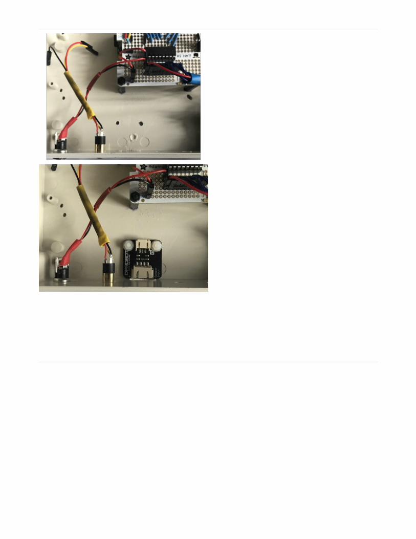
Wire everything up. Notice I have passed the optical sensor breakout board 3 wire ribbon from beneath the Perma-Proto HAT. Make sure 5V (Red), GND (black) and GPIO 17 (green) wires are connected correctly.
© Adafruit Industries https://learn.adafruit.com/reef-pi-water-level-controller Page 10 of 15

Here is a close up of the build with all optical sensor
attached, along with rest of the sensor and connections.
That's it reef-pi ATO build is complete. Next, we'll go
through the configuration and testing of our ATO
controller.
© Adafruit Industries https://learn.adafruit.com/reef-pi-water-level-controller Page 11 of 15

Configuration &Testing
Power up your reef-pi controller once all the sensors are connected alongside the power strip. Connect the reef-pi toyour computer and go to the reef-pi user interface (UI) to configure the new ATO controller.
Digital inputs, such as optical sensors, are represented as inlets in reef-pi. Inlets are then associated with ATOcontrollers to monitor water level sensor and turn on or off ATO pump (a submersible or peristaltic pump, declared asan equipment in reef-pi).
To create an inlet, navigate to the connectors section under the Configuration tab. Create a new inlet by clicking onthe "+" button. Specify a name and GPIO pin number. In our case the GPIO pin number is 17. I am naming the inlet as"Optical Sensor".
Once created the new inlet will be visible in the UI.
Next, head over to the ATO tab. Create a new ATO by clicking one "+" button. Associate the newly created inlet with it.We'll name it as Adafruit. Notice default check frequency is set to 120 seconds. This means reef-pi will check the inlet(the optical sensor in this case) every 120 seconds and switch on or off the control pump if specified. The ATO Statusdrop-down menu controls whether the ATO will be enabled or disabled.
Once created, the ATO controller will start monitoring the inlet. Since the optical water level sensor is out of water, the
Inlets and Outlets in reef-pi are always associated with GPIO pin numbers. These are not serial numbers of the pins (for example GPIO 17 pin is the 11th pin)�
© Adafruit Industries https://learn.adafruit.com/reef-pi-water-level-controller Page 12 of 15

ATO control pump will be turned on. We can expand the ATO controller to see the usage chart which shows hourlyATO control pump usage in seconds.
For more comprehensive physical testing, use a table lamp or any other suitable AC device to simulate turning on acontrol pump and a cup of water to simulate the water level changes. Reduce the ATO control frequency to a smallercheck interval (for example 2 seconds). Now, if you submerge the optical water level sensor inside the cup of water,the table lamp should turn off within a couple of seconds and if the optical water level sensor is moved out of waterreef-pi should turn on the table lamp.
ATO controller in reef-pi is built by connecting an inlet item with an equipment item. Though it is built for water levelcontrol (and salinity indirectly) it can be used to automate a host of things, since mechanical switches, float switches,etc. can also be used as inlets.
A lower check interval will cause higher CPU usage in reef-pi. reef-pi allows charting CPU and memory usage (enablethe health check feature in configuration). Keep a watch on those graphs to understand if your controller is loadingyour CPU.
Thank you for reading through the water level controller guide. We'll go through the lighting controller in the next reef-
© Adafruit Industries https://learn.adafruit.com/reef-pi-water-level-controller Page 13 of 15

pi guide.
© Adafruit Industries https://learn.adafruit.com/reef-pi-water-level-controller Page 14 of 15

© Adafruit Industries Last Updated: 2019-12-28 01:15:41 AM UTC Page 15 of 15


![PI CONTROLLER BASED SHUNT CONNECTED THREE ...realize the potential and feasibility of PI controller [17], [18]. (a) Current Wave of Current Controller (b) Current Controller Waveform](https://img.dokumen.tips/doc/110x75/604b4b4b953f6a233834072a/pi-controller-based-shunt-connected-three-realize-the-potential-and-feasibility.jpg)