Embed Size (px)
Citation preview

1
REDUCING ANTENNA VISUAL SIGNATURE USING META-MATERIALS
Dr. Kamal Sarabandi Dept. of Electrical Engineering and Computer Science
The University of Michigan 3228 EECS Building
1301 Beal Avenue Ann Arbor, MI 48109-2122
George Palafox*
U.S. Army Communications-Electronics Research, Development & Engineering Center Building 2700, Myer Center Fort Monmouth, NJ 07703
ABSTRACT
The current as well as planned family of Army vehicles requires multiple antennas to meet the growing communications requirements and therefore exhibit a significantly large visual signature. Antenna size is dictated by frequency and the lower the frequency, the larger the antenna. At VHF and UHF frequencies, the primary military tactical communication bands, antennas have a significant visual signature. The visual signature exhibited by these antennas increases the vulnerability of the platforms. Low profile and conformal antenna technologies have a great potential to reduce or even eliminate antenna visual signatures thereby having a significant effect on vehicle survivability. In this paper, we propose a technique for significantly reducing the antenna visual signature. This technique involves printing the antenna on a high Reactive Impedance Surface (RIS) permittivity substrate or Meta-Material. We have chosen the UHF Enhanced Position Location Radio System (EPRLS) AS-3449 antenna, a 1-meter whip structure as a baseline for this research. The proposed technique uses known patch antenna geometries as the antenna radiation elements with a substantially reduced signature while retaining the radiation characteristics of the EPLRS antenna. We present a computer model of the antenna with computer simulation results along with the antenna prototype with the experimental results.
1. INTRODUCTION
A large antenna visual signature on a platform results in the ability of an enemy to detect the platform at a far distance. The number of antennas on the platform gives the enemy an indication of the vehicle’s significance thus reducing the platform’s survivability and subsequently compromising the entire unit’s functionality through the potential loss of command and control. To resolve the problem, the antenna visual signature on platforms has to be reduced. Meta-materials allow the antenna’s physical geometry to be reduced substantially while retaining similar radiation characteristics.
Meta-Material are substrates of high permittivity coupled with RIS. Through an In-House Laboratory Investigation Research (ILIR) project, an EPLRS antenna with reduced visual signature was developed by the University of Michigan and tested at the U.S. Army Communications-Electronics Research, and Development & Engineering Command (CERDEC) and the Army Research Laboratories (ARL). In the proceeding sections, the proposed approach will be presented, followed by the modeled and experimental results and a conclusion.
2. PROPOSED APPROACH In order to understand how the antenna geometry can be reduced when coupled with a Meta-Material, a Finite Difference Time Domain model was developed as shown in Fig 1.
Fig. 1 FDTD Antenna Model. 2.1 Finite Difference Time Domain (FDTD) The Finite Difference Time Domain (FDTD) technique [1] was used to model the material substrate used as the Meta-Material. The University of Michigan modeled the antenna shown in Fig1. FDTD is based on Maxwell’s curl equations.
HEt
Hμρ
μ'1
−×∇−=∂∂ (1)
EHtE
εσ
ε−×∇−=
∂∂ 1 (2)
Report Documentation Page Form ApprovedOMB No. 0704-0188
Public reporting burden for the collection of information is estimated to average 1 hour per response, including the time for reviewing instructions, searching existing data sources, gathering andmaintaining the data needed, and completing and reviewing the collection of information. Send comments regarding this burden estimate or any other aspect of this collection of information,including suggestions for reducing this burden, to Washington Headquarters Services, Directorate for Information Operations and Reports, 1215 Jefferson Davis Highway, Suite 1204, ArlingtonVA 22202-4302. Respondents should be aware that notwithstanding any other provision of law, no person shall be subject to a penalty for failing to comply with a collection of information if itdoes not display a currently valid OMB control number.
1. REPORT DATE 01 NOV 2006
2. REPORT TYPE N/A
3. DATES COVERED -
4. TITLE AND SUBTITLE Reducing Antenna Visual Signature Using Meta-Materials
5a. CONTRACT NUMBER
5b. GRANT NUMBER
5c. PROGRAM ELEMENT NUMBER
6. AUTHOR(S) 5d. PROJECT NUMBER
5e. TASK NUMBER
5f. WORK UNIT NUMBER
7. PERFORMING ORGANIZATION NAME(S) AND ADDRESS(ES) Dept. of Electrical Engineering and Computer Science The University ofMichigan 3228 EECS Building 1301 Beal Avenue Ann Arbor, MI 48109-2122
8. PERFORMING ORGANIZATIONREPORT NUMBER
9. SPONSORING/MONITORING AGENCY NAME(S) AND ADDRESS(ES) 10. SPONSOR/MONITOR’S ACRONYM(S)
11. SPONSOR/MONITOR’S REPORT NUMBER(S)
12. DISTRIBUTION/AVAILABILITY STATEMENT Approved for public release, distribution unlimited
13. SUPPLEMENTARY NOTES See also ADM002075., The original document contains color images.
14. ABSTRACT
15. SUBJECT TERMS
16. SECURITY CLASSIFICATION OF: 17. LIMITATION OF ABSTRACT
UU
18. NUMBEROF PAGES
26
19a. NAME OFRESPONSIBLE PERSON
a. REPORT unclassified
b. ABSTRACT unclassified
c. THIS PAGE unclassified
Standard Form 298 (Rev. 8-98) Prescribed by ANSI Std Z39-18

2
Yee’s Algorithm is used to calculate Maxwell’s curl equations based on finite difference approximations of space derivatives and time derivatives. Two key parameters that are important for accuracy and stability when using the FDTD technique are the cell size (α) and the time step (Δt) [1].
10λα ≤ (3)
( ) ( ) ( )222
1111
zyx
t
Δ+
Δ+
Δ
≤Δ (4)
The maximum cell size must be less than or equal to 1/10th (some cases 1/20th) the wavelength of the highest operational frequency. In this paper, a FDTD model of the EPLRS antenna is presented where the geometry is a stacked dipole configuration as shown in Fig 2.
Fig. 2 FDTD EPLRS Model. The EPLRS antenna model is presented to compare its performance with the redesigned EPLRS Meta-Material antenna. For the EPLRS antenna, the maximum cell size of 1cm cubes edges was used. 2.1 EPLRS Antenna Gain At Azimuth 90 degrees, it has omni-directional performance with an average gain of +4 dBi. Depending on the manufacturer, this gain can vary within ±1dBi. Shown in Fig 3 is the gain of the FDTD model of the EPLRS antenna at boresight.
Fig. 3 Gain in (dBi) of EPLRS Antenna FDTD Model.
3. EPLRS ANTENNA RE-DESIGN USING META-MATERIALS
The University of Michigan developed an FDTD miniaturized planar antenna model using a novel substrate shown in Fig 1. A microstrip patch antenna was used as the candidate antenna since it has low profile planar geometry and offers simplicity in fabrication and integration with electronic parts of a communication system. However, the drawbacks of this antenna configuration are limited operational bandwidth, which will be exasperated when the size is reduced. 3.1 Multi-resonance Antenna Designs
To mitigate the limitation on the operational bandwidth, the use of multi-resonance antennas is proposed. Two patch antenna configurations are considered: a T-slot Fig 4a and a U-slot Fig 4b.
Fig. 4 (a) Patch Antenna with T-Slot; (b) Patch Antenna with
U-slot. The idea is to locate several radiators with adjacent resonant frequencies within an available radiating aperture. In this process, its important to ensure that the current distribution over the antenna at all resonant frequencies be the same in order for the antenna to provide the same polarization over the band of operation. Simulation runs of the T-slot antenna (shown in Fig 4) have a return loss shown in Fig 5a demonstrating that the

3
antenna has two resonances with wide bandwidth of about 400 – 520 MHz.
Fig. 5 (a) Return Loss of T-slot FDTD Model; (b) Return Loss
of U-Slot FDTD Model. In Fig 5a, it is demonstrated that the antenna has two resonances, the first due to the slot radiation and the second caused by the patch radiation. The current distributions at both resonant frequencies are similar and therefore the antenna polarization is fixed over the bandwidth. The patch U-slot antenna has three resonances between 360 – 520 MHz as shown in Fig 5b. The first resonance is due to the U slot radiator and the second and third resonances are due to the length and width (second mode) patch radiations. As shown, wideband performance can be achieved by utilizing the multi-resonance patch-slot antennas. However, the main issue is the large size of the antenna. The T-slot including the substrate has total size of 50x65x5 cm and the U-slot has a total size including the substrate of 90x95x7 cm. Antenna miniaturization may be achieved by printing the antenna on a high permittivity substrate but because of the existence of a strong coupling between the antenna and its ground plane a large amount of energy is trapped inside the substrate which significantly reduces the bandwidth of each resonance and a wideband characteristic cannot be achieved. In addition to this, the antenna radiation efficiency is degraded. 3.2 Reactive Impedance Surface (RIS) Solution The standard approach, as discussed, for miniaturizing a patch antenna is based on the application of high permittivity materials where the antenna is printed on a high dielectric substrate with a low loss tangent. However, the major issue with this approach is the difficulty in impedance matching and the narrow bandwidth of these designs. These problems are the direct result of a strong coupling between the antenna and its ground plane, which results in trapping the EM waves inside the substrate (strong near-field) and increase the Q of the antenna (reduction in the antenna bandwidth). This problem also exists for a multi-resonant patch antenna printed on a substrate of high permittivity. An even more difficult issue is merging the resonant frequencies to acquire wideband operation.
To overcome the aforementioned problems, a RIS is used instead of a ground plane. The RIS is an engineered meta-substrate that has the potential to miniaturize the size of the antenna while reducing the coupling between the antenna and its ground plane. Therefore, a multi-resonant antenna printed on a RIS can offer a wideband behavior while at the same time allowing the antenna to become more compact. The RIS can be designed to provide a minimum interaction with the antenna above it. This fundamental operation allows for wideband operation and ease of impedance match. The RIS has three main features: (1) has a significant antenna front to back ratio similar to having a Perfect Electrical Conductor (PEC) ground plane, (2) reduces the coupling between the antenna and its ground plane and thus enhances the impedance match over a wide bandwidth, and (3) combines inductive (capacitive) behavior of the RIS with the capacitive (inductive) property of the antenna below its resonance to tune the resonance at a much lower frequency and thus achieving antenna miniaturization. A reactive impedance surface is designed using a capacitive layer backed by a metallic surface. The resonant frequency of such a surface depends on the value of the capacitive elements, the distance between the capacitive layer, and the back metal, and the dielectric constant of the material in between. To design a RIS at the UHF band with a relatively low layer thickness and a moderate dielectric constant, high capacitive values are needed. This can be accomplished using interdigital capacitors in a periodic fashion. Fig 6a illustrates the geometry of a RIS at UHF.
Fig. 6 (a) RIS, (b) Surface Impedance Characteristic. The RIS is a periodic array of crossed dipoles coupled through the interdigital capacitors printed on a dielectric material backed by a PEC. The structure is equivalent to a parallel LC circuit whose input impedance is always reactive. The normalized impedance of the surface is computed using FDTD shown in Fig 6b. As shown, the surface below its resonant frequency behaves inductively that can tune a capacitive radiating element to radiate at a lower frequency.

4
3.3 Patch Antenna Reduction The RIS is used with the U-slot patch to achieve a miniaturized antenna. This process is complicated with many free parameters to be optimized for achieving the desired bandwidth and miniaturized size. Shown in Fig 7a is the geometry of the miniaturized UHF patch on a RIS. The antenna has a compact size occupying a volume of 22x22x3 cm. Shown in Fig 7b is the return loss of the antenna after optimization.
Fig. 7 (a) Compact U-slot antenna printed on the RIS, (b)
Compact U-slot Return Loss. It is shown that the miniaturized size antenna provides a very wide bandwidth. The RIS reduced the size of the antenna while maintaining the wide bandwidth of the structure. 3.4 Compact U-slot Antenna Radiation Characteristics The FDTD antenna model shows a consistent radiation pattern over the entire range of operation with a very low cross-polarized radiation. The E-plane and H-plane radiation patterns of the antenna at Frequency A and B are shown in Fig 8a and Fig 8b.
Fig. 8 (a) E- and H- plane pattern at A, (b) E- and H- plane pattern at B.
The FDTD simulation results show that the compact U-slot antenna has comparable performance to the EPLRS 1-meter whip. The next step is to manufacture and measure a prototype compact U-slot antenna.
4. COMPACT U-SLOT ANTENNA PROTOTYPE AND MEASUREMENTS
Modeling and Simulation have shown that the compact
U-slot antenna has comparable performance as the EPLRS antenna. The design procedure and simulated performance of the U-slot patch is capable of providing the required bandwidth of EPLRS. 4.1 Compact Antenna Prototype The patch and RIS pattern were etched using chemical lithography on a Rogers TMM4 substrate with 0.334” or 0.85 cm thickness having a dielectric constant of 4.5. The prototype of the compact antenna is shown in Fig 9.
Fig. 9 Compact U-slot Antenna Prototype The substrate has a square shape where the sides measure 22 cm and has thickness of 1cm. In Fig 10, the RIS prototype is shown.
Fig. 10 RIS The substrate is glued to a very high quality ceramic with permittivity 10.2 and a thickness of 2cm fabricated by Trans-Tech. The ceramic was fabricated in two pieces and glued together as shown in Fig 11.
Fig. 11 Ceramic Substrate with thickness of 2cm and ε = 10.2.
5
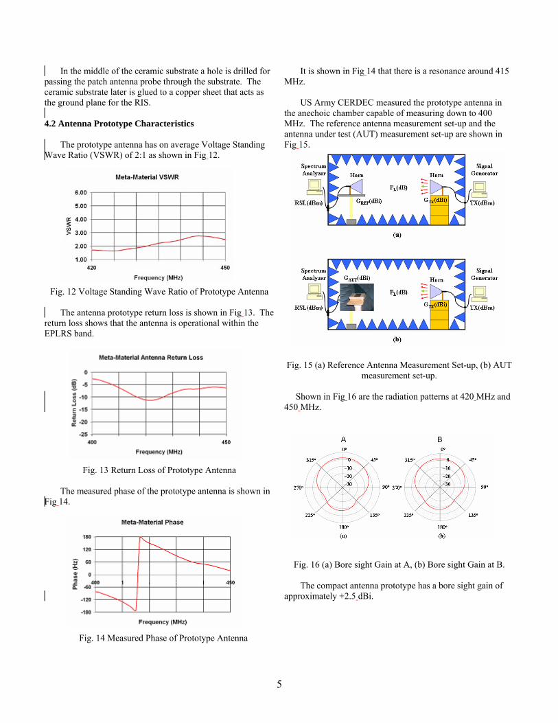
In the middle of the ceramic substrate a hole is drilled for passing the patch antenna probe through the substrate. The ceramic substrate later is glued to a copper sheet that acts as the ground plane for the RIS. 4.2 Antenna Prototype Characteristics The prototype antenna has on average Voltage Standing Wave Ratio (VSWR) of 2:1 as shown in Fig 12.
Fig. 12 Voltage Standing Wave Ratio of Prototype Antenna The antenna prototype return loss is shown in Fig 13. The return loss shows that the antenna is operational within the EPLRS band.
Fig. 13 Return Loss of Prototype Antenna
The measured phase of the prototype antenna is shown in Fig 14.
Fig. 14 Measured Phase of Prototype Antenna
It is shown in Fig 14 that there is a resonance around 415 MHz. US Army CERDEC measured the prototype antenna in the anechoic chamber capable of measuring down to 400 MHz. The reference antenna measurement set-up and the antenna under test (AUT) measurement set-up are shown in Fig 15.
Fig. 15 (a) Reference Antenna Measurement Set-up, (b) AUT
measurement set-up. Shown in Fig 16 are the radiation patterns at 420 MHz and 450 MHz.
Fig. 16 (a) Bore sight Gain at A, (b) Bore sight Gain at B.
The compact antenna prototype has a bore sight gain of approximately +2.5 dBi.

6
Fig. 17 EPLRS vs Compact Meta-Material Antenna Boresight Gain Comparison
From Fig 17, it is seen that the Compact Meta-Material antenna has comparable performance to the EPLRS antenna. The patch antenna has inherently poor gain performance at end-fire. Therefore, the compact meta-material antenna has poor performance at end-fire. Fig 18 shows the performance of the compact antenna at azimuth angle 90 degrees.
Fig. 18 Compact Meta-Material Antenna at Horizon (Azimuth Angle = 90 degrees)
The pattern shown in Fig 18 tells us that this antenna has poor gain but can be improved at end-fire. This antenna performs optimally at boresight.
CONCLUSIONS Antennas with pronounced visual signature on military platforms can potentially aid the enemy in detecting the platforms location. This paper presented a method to substantially reduce the visual signature of such antennas. In this paper, the EPLRS antenna is investigated as a potential candidate for size reduction. Meta-Materials allow for large antenna geometries to be reduced in size while retaining comparable antenna characteristics. To obtain the desired EPLRS bandwidth, a
Meta-substrate was used along with multi-resonant microstrip antenna geometries. To obtain a more compact antenna along with better impedance matching, the concept of a RIS was introduced. These techniques allow for an EPLRS antenna that has a significantly large reduction in signature while retaining comparable antenna characteristics. Currently, the compact meta-material antenna is heavy in weight. Weight is attributed to the chosen Meta-substrate. A material of lighter weight can be chosen for the next prototype iteration. Based on the antenna performance, in order to obtain optimal performance using this antenna, possible locations on platforms for this antenna are vehicle side locations. The EPRLS antenna performs slightly better by 2 dB. However, future iteration trials of prototypes can improve and eventually equally match the performance of the EPLRS antenna with the added feature of reduced visual signature.
ACKNOWLEDGEMENTS
This research was performed by the University of Michigan. Dr. Kamal Sarabandi, was funded through an ILIR to support this effort.
REFERENCES [1] Kunz, Karl S., and Luebbers, Raymond J. Finite Difference Time Domain Method for Electromagnetics,
CRC Press, NY, 1993 [2] C. A. Balanis, Antenna Theory, 2nd Ed. New York: Wiley, 1982, pp.722–752. [3] K. Buell, D. Cruickshank, H. Mosallaaei, and Kamal Sarabandi, “Patch Antenna over RIS Substrate: A Novel Miniaturized Wideband Planar Antenna Design,” IEEE Trans. Antennas Propagation, pp. 269 – 272, June 2003.
Reducing Antenna Visual Signature Using Meta-Materials
28 November 2006
Space & Terrestrial Communications Directorate
George Palafox
Kamal [email protected], 732-427-2415

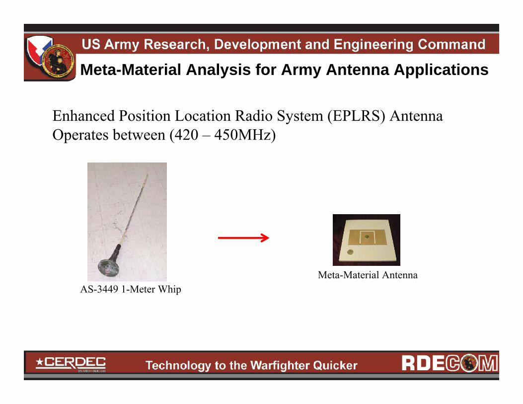
Meta-Material Analysis for Army Antenna Applications
At VHF and UHF Frequencies, the λ is large and therefore the antenna exhibits a large signature.
Using Meta-Materials, Whip Antennas can be reduced significantly in size.
Ground-to-Air Communications
Ground-to-Ground Communications
Meta-Material Analysis for Army Antenna Applications
Enhanced Position Location Radio System (EPLRS) AntennaOperates between (420 – 450MHz)
AS-3449 1-Meter WhipMeta-Material Antenna
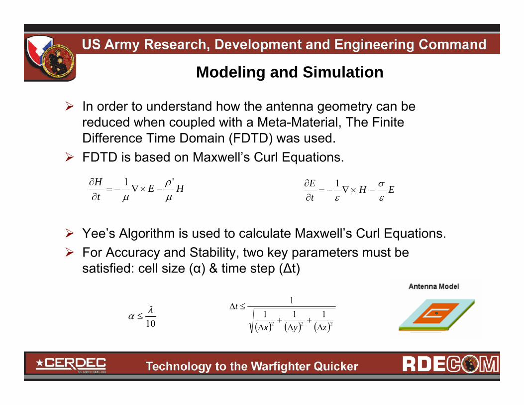
In order to understand how the antenna geometry can be reduced when coupled with a Meta-Material, The Finite Difference Time Domain (FDTD) was used.FDTD is based on Maxwell’s Curl Equations.
Yee’s Algorithm is used to calculate Maxwell’s Curl Equations.For Accuracy and Stability, two key parameters must be satisfied: cell size (α) & time step (Δt)
Modeling and Simulation
HEtH
μρ
μ'1
−×∇−=∂∂
EHtE
εσ
ε−×∇−=
∂∂ 1
10λα ≤
( ) ( ) ( )222111
1
zyx
t
Δ+
Δ+
Δ
≤Δ

Modeling and Simulation
To compare results from the Meta-Material Antenna with the EPLRS AS-3449 Antenna, the EPLRS Antenna was modeled using FDTD. The EPLRS Antenna geometry is a stacked dipole configuration.The EPLRS Antenna has gain of (+4dBi) – (+5dBi) with its band of operation.EPLRS Antenna has omni-directional performance.1 cm cell size was used for the FDTD Model
EPLRS Antenna FDTD Model
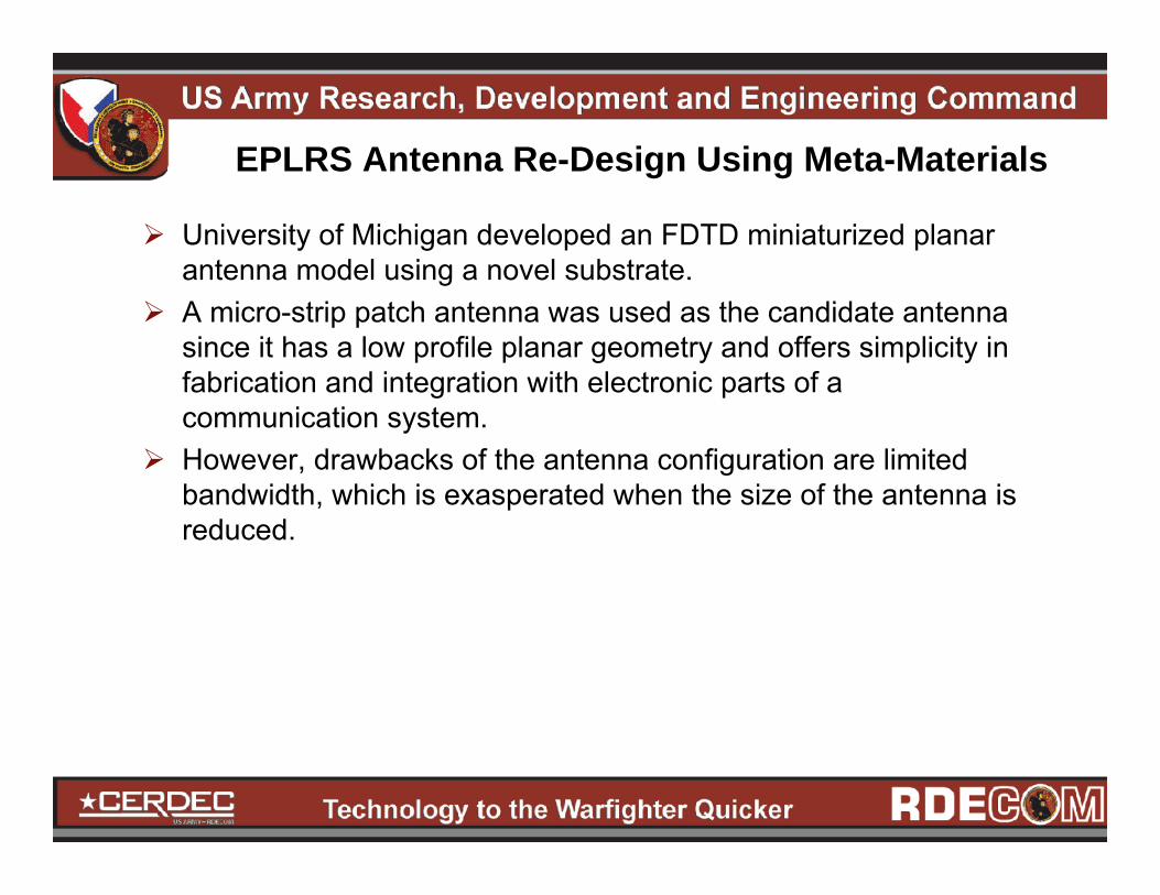
EPLRS Antenna Re-Design Using Meta-Materials
University of Michigan developed an FDTD miniaturized planar antenna model using a novel substrate.A micro-strip patch antenna was used as the candidate antenna since it has a low profile planar geometry and offers simplicity in fabrication and integration with electronic parts of a communication system.However, drawbacks of the antenna configuration are limited bandwidth, which is exasperated when the size of the antenna is reduced.
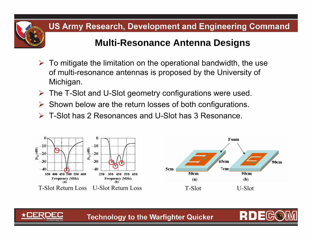
Multi-Resonance Antenna Designs
To mitigate the limitation on the operational bandwidth, the useof multi-resonance antennas is proposed by the University of Michigan.The T-Slot and U-Slot geometry configurations were used.Shown below are the return losses of both configurations.T-Slot has 2 Resonances and U-Slot has 3 Resonance.
T-Slot U-SlotT-Slot Return Loss U-Slot Return Loss

Multi-Resonance are still large Antennas
Wide-Band performance is achieved using Multi-Resonant AntennasT-Slot is 50x65x5cm (To Large)U-Slot is 90x95x7cm (To Large)Antenna Miniaturization may be achieved by printing the antenna on a high permittivity substrate but because of existence of a strong coupling between the antenna and its ground plane a large amount of energy is trapped inside the substrate which reduces the bandwidth of each resonance and wideband characteristics are not achieved.
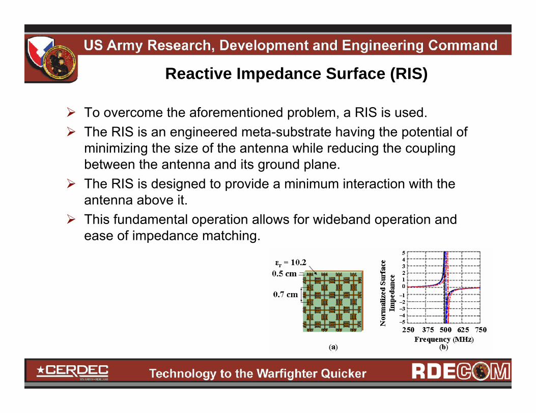
Reactive Impedance Surface (RIS)
To overcome the aforementioned problem, a RIS is used. The RIS is an engineered meta-substrate having the potential of minimizing the size of the antenna while reducing the coupling between the antenna and its ground plane.The RIS is designed to provide a minimum interaction with the antenna above it.This fundamental operation allows for wideband operation and ease of impedance matching.
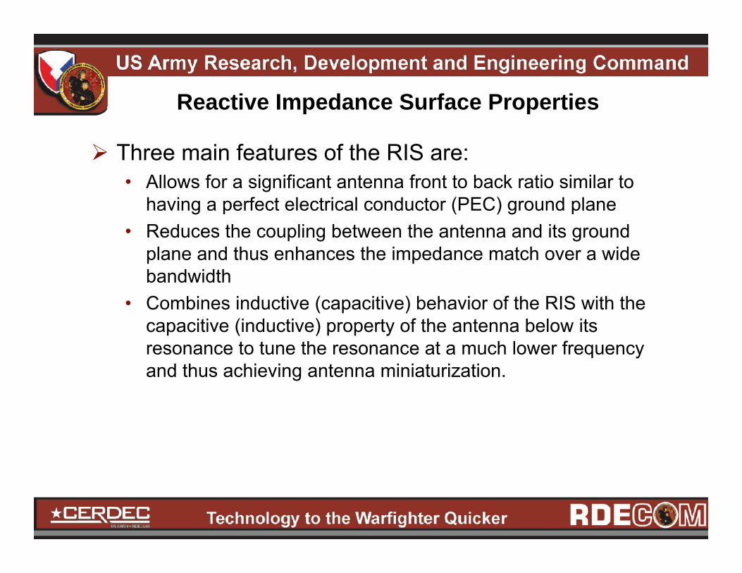
Reactive Impedance Surface Properties
Three main features of the RIS are:• Allows for a significant antenna front to back ratio similar to
having a perfect electrical conductor (PEC) ground plane• Reduces the coupling between the antenna and its ground
plane and thus enhances the impedance match over a wide bandwidth
• Combines inductive (capacitive) behavior of the RIS with the capacitive (inductive) property of the antenna below its resonance to tune the resonance at a much lower frequency and thus achieving antenna miniaturization.

RIS DesignThe RIS is a periodic array of crossed dipoles coupled through the interdigital capacitors printed on a dielectric material backed by a PEC.The RIS is designed using a capacitive layer backed by a metallic surface. The resonant frequency of this surface depends on the value of the capacitive elements, the distance between the capacitive layer and the back element and the dielectric constant of the material in between.To design a RIS at the UHF band with a relatively low layer thickness and a moderate dielectric constant, high capacitive values are needed. This can be accomplished using interdigital capacitors is a periodic fashion.

Miniaturization of Antenna
The RIS + U-Slot Patch Antenna is used to achieve a miniaturized antenna.The new antenna now occupies a volume of 22x22x3cmThe antenna covers the frequency range: 406 – 458MHz.

Compact U-Slot Model Antenna Radiation Characteristics
FDTD Model shows a consistent radiation pattern over the entire range of operation with very low cross-polarized radiation.The FDTD simulation results show that the compact U-Slot Antenna has comparable performance to the EPLRS 1-Meter Whip Antenna.
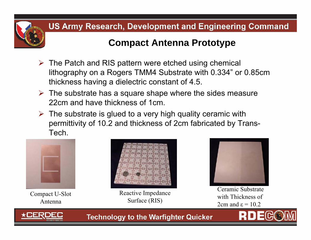
Compact Antenna Prototype
The Patch and RIS pattern were etched using chemical lithography on a Rogers TMM4 Substrate with 0.334” or 0.85cm thickness having a dielectric constant of 4.5. The substrate has a square shape where the sides measure 22cm and have thickness of 1cm.The substrate is glued to a very high quality ceramic with permittivity of 10.2 and thickness of 2cm fabricated by Trans-Tech.
Compact U-Slot Antenna
Reactive Impedance Surface (RIS)
Ceramic Substrate with Thickness of 2cm and ε = 10.2

Antenna Prototype Characteristics
The Antenna prototype has on average a Voltage Standing Wave Ratio (VSWR) of 2:1The return loss shows that the antenna is operational within theEPLRS band.The phase response illustrates a resonance at 415MHz.

Antenna Radiation Patterns
US Army CERDEC measured the prototype antenna in the anechoic chamber capable of measuring down to 400MHz.The antenna has a bore sight gain of ≈ +2.5dBi
Chamber Measurement Set-Up
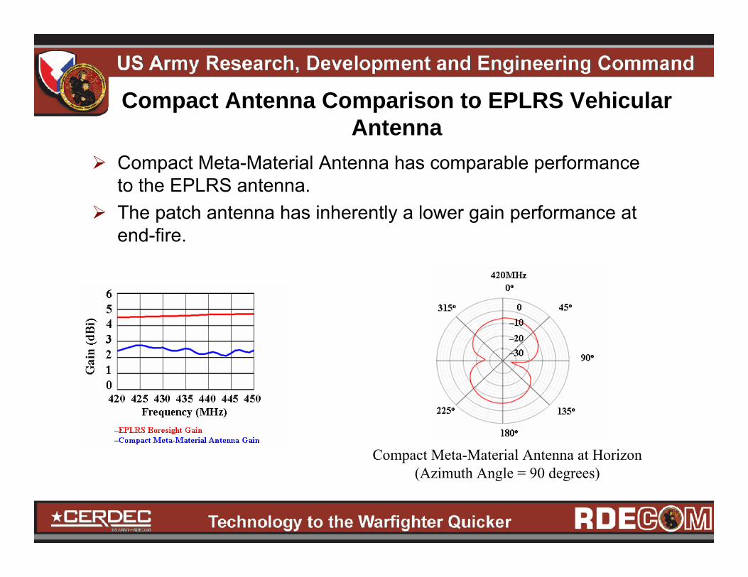
Compact Antenna Comparison to EPLRS Vehicular Antenna
Compact Meta-Material Antenna has comparable performance to the EPLRS antenna.The patch antenna has inherently a lower gain performance at end-fire.
Compact Meta-Material Antenna at Horizon (Azimuth Angle = 90 degrees)
ConclusionsAntennas with pronounced visual signature on military platforms can potentially aid the enemy in detecting the platforms location. This paper presented a method to substantially reduce the visual signature of such antennas. Meta-Materials allow for large antenna geometries to be reduced in size while retaining comparable antenna characteristics.The Meta-Material and RIS allowed a 1-Meter Whip antenna be reduced to a 22x22x3cm patch antenna.Notable concerns with the antenna prototype are the weight and the end-fire performance.

AcknowledgementsDr. Kamal Sarabandi of Michigan UniversityDr. Felix Schwering from US Army CERDECDr. Mahbub Hoque from US Army CERDECMr. Steven Goodall from US Army CERDEC

Questions???
Any Questions???


![META [DADOS] / META [DATA]](https://img.dokumen.tips/doc/110x75/5790780b1a28ab6874c09b8f/meta-dados-meta-data.jpg)