Embed Size (px)
Citation preview

Reduced InstructionSet Computers
Raul Queiroz Feitosa
Parts of these slides are from the support material provided by W. Stallings
RISC 2
Objective
To provide an overview of the innovations in the areas of computer organization and architecture related to Reduced Instruction Set Computers.

RISC 3
Outline
� Historical Overview
� Instruction Execution Characteristics
� Use of Large Register File
� Reduced Instruction Set Architecture
� RISC Pipelining
RISC 4
Driving forces for CISC
� Software costs far exceed hardware costs
� Increasingly complex high level languages
� Semantic gap
� Leads to:
� Inefficient code
�Excessive machine program size
�Compiler complexity
�Small register sets
RISC 5
Driving forces for CISC
� Access to control memory faster than to external memory
� Leads to:
�Move complexity to microcode
�Larger and more powerful instruction sets
�More addressing modes
�Hardware implementations of HLL statements� e.g. CASE (switch) on VAX
RISC 6
Changes toward RISC
� The semiconductor technology and cache memories → reduced the memory access time
� Compiler technology evolved → more intelligence built in compilers
� Pipelining → see later.
� The program’s dynamic behavior started being investigated
RISC 7
Outline
� Historical Overview
� Instruction Execution Characteristics
� Use of Large Register File
� Reduced Instruction Set Architecture
� RISC Pipelining
RISC 8
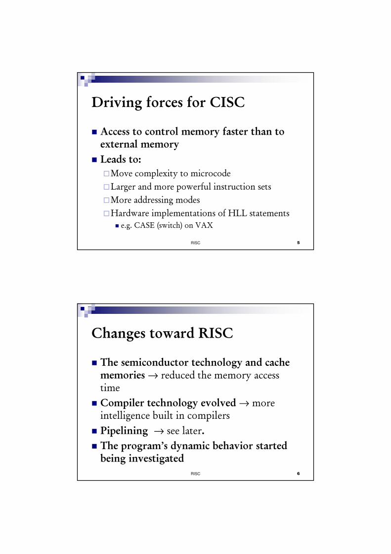
Frequency of HLL Operations
Procedure call/return is the most time consuming operation in typical HLL.

RISC 9
Operands
Furthermore, 80% of the scalars are local to procedures →→→→ optimisation should concentrate on accessing local variables.
RISC 10
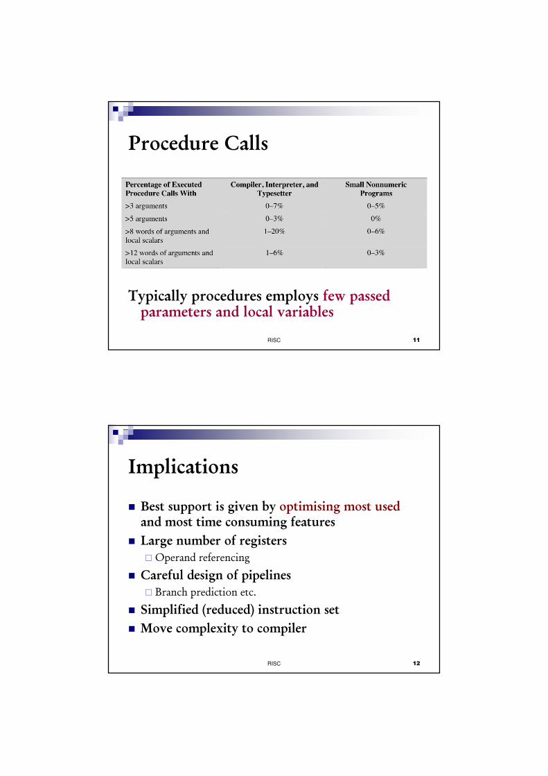
Procedure Calls
Registers are saved by calling and restored by returning →→→→ very time consuming
Programs mostly confined to a narrow window of procedure invocation depth
RISC 11
Procedure Calls
Typically procedures employs few passed parameters and local variables
RISC 12
Implications
� Best support is given by optimising most usedand most time consuming features
� Large number of registers� Operand referencing
� Careful design of pipelines� Branch prediction etc.
� Simplified (reduced) instruction set
� Move complexity to compiler

RISC 13
Outline
� Historical Overview
� Instruction Execution Characteristics
� Use of Large Register File
� Reduced Instruction Set Architecture
� RISC Pipelining
RISC 14
Large Register File
� Software solution
�Require compiler to allocate registers
�Allocate based on most used variables in a given time
�Requires sophisticated program analysis
� Hardware solution
�Have more registers
�Thus more variables will be in registers

RISC 15
SW Based Register Optimization
� Assume small number of registers (16-32)
� Optimizing use is up to compiler
� HLL programs have no explicit references to registers� usually - think about C - register int
� Assign symbolic or virtual register to each candidate variable
� Map (unlimited) symbolic registers to real registers
� Symbolic registers that do not overlap can share real registers
� If you run out of real registers some variables use memory
RISC 16
Graph Coloring
← Actual registers
A B C D E F
tim
e
R1 R2 R3
Symbolic registers
DE
A B
DC E F
Time sequence of active use of registers
Register interference graph
� Symbolic register that are
simultaneously in use are connected
by an edge and are assigned different
colors
� The aim is to minimize the number of
different colors.

RISC 17
HW Solution - Register WindowRegister set is split in windows, just one window
visible at a time. A window has three fields:Input parameter & returned results
Local variables Input parameter &
returned results of the procedure called by current procedure
Parameter
Registers
Local
Registers
Temporary
Registers
Window of level J
Window of level J+1
Parameter
Registers
Local
Registers
Temporary
Registers
overlap
RISC 18
Circular Buffer
A.p
F.t
B.p
A.tC.p
B.t
D.p
C.t
E.p
D.t
F.p
E.t
A.l
B.l
C.l
D.l
E.l
F.l
WA
WB
WC
WD
WE
WF
Saved
window
pointer
(SWP)
Restore
Save
Current W
indow
pointer (CW
P)
Return
Call
� Only one window register is visible,
the one pointed by CWP
� Register references are offset by CWP
� If procedure E calls F, arguments for F
are placed in E.t, and CWP advances
one window
� SWP identifies the window most
recently saved in memory
� If procedure F calls another one,
CWP=SWP, an interrupt occurs, and
the A window is saved.Current W
indow
pointer (CW
P)

RISC 19
Global Variables
� Allocated by the compiler to memory
� Inefficient for frequently accessed variables
� Have a set of registers for global variables
RISC 20
Registers × Cache

RISC 21
Outline
� Historical Overview
� Instruction Execution Characteristics
� Use of Large Register File
� Reduced Instruction Set Architecture
� RISC Pipelining
RISC 22
RISC Characteristics
1. One instruction per cycle
2. Register to register operationsEx.: addu r1,r2,r4 /* add unsigned r2 to r4
and put in r1
addu r1,#imm(r4) /* add unsigned r1 to memory
address r4 offset #imm
3. Memory access only through Load/Store
4. Few, simple addressing modesEx.: lw r2,128(r3) /* load address 128 offset
from r3 into r2 .
FORBIDDEN

Ex.: Intel x86
RISC 23
RISC Characteristics
5. Few, simple, fixed instruction formats
6 5 5 5 5 6
Operation rs rt rd Shift Function
Operation rs rt Immediate
6 5 5 5 5 6
Operation Target
6 26
I-type
(immediate
J-type
(jump)
R-type
(register
Operation
Rs
Rt
Immediate
Target
Rd
Shift
Function
Operation Code
Source register specifier
Source/destination register specifier
Immediate, branch, or address displacement
Jump target address
Destination register specifier
Shift amount
ALU/shift function specifier
6 5 5 5 5 6
Operation rs rt rd Shift Function
Operation rs rt Immediate
6 5 5 5 5 6
Operation Target
6 26
I-type
(immediate
J-type
(jump)
R-type
(register
Operation
Rs
Rt
Immediate
Target
Rd
Shift
Function
Operation Code
Source register specifier
Source/destination register specifier
Immediate, branch, or address displacement
Jump target address
Destination register specifier
Shift amount
ALU/shift function specifier
Ex.: MIPS R4000
RISC 24
RISC Characteristics
6. Hardwired design (no microcode)
7. More compile time/effort

RISC 25
Outline
� Historical Overview
� Instruction Execution Characteristics
� Use of Large Register File
� Reduced Instruction Set Architecture
� RISC Pipelining
RISC 26
RISC Pipelining
� Delayed branch� Delayed Load
� Register to be the target is locked by processor
� Continue execution of instruction stream until register required
� Idle until load complete� Re-arranging instructions
can allow useful work whilst loading
� Loop Unrolling
Load rA ← M1
Load rB ← M2
Load rC ← M3
Load rD ← M4
Add rE ← rA+rB
NOOP
Add rF ← rC+rD
Ex.: load complete after 2
instruction cycles
RISC 27
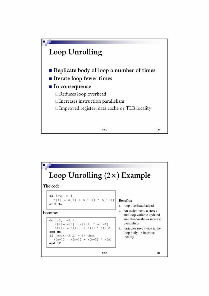
Loop Unrolling
� Replicate body of loop a number of times
� Iterate loop fewer times
� In consequence
�Reduces loop overhead
� Increases instruction parallelism
� Improved register, data cache or TLB locality
RISC 28
Loop Unrolling (2×) ExampleThe code
do i=2, n-1
a[i] = a[i] + a[i-1] * a[i+l]
end do
becomes
do i=2, n-2,
= + a[i-1] *
= + * a[i+2]
end do
if (mod(n-2,2) = i) then
a[n-1] = a[n-1] + a[n-2] * a[n]
end if
Benefits:
1. loop overhead halved
2. An assignment, a stores
and loop variable updated
simultaneously → increase
parallelism
3. variables used twice in the
loop body → improve
locality
2
a[i]
a[i+l]
= a[i] a[i+1]
= a[i+l] a[i]

RISC 29
Controversy� Quantitative
� compare program sizes and execution speeds
� Qualitative� examine issues of high level language support and use of
VLSI real estate
� Problems� No pair of RISC and CISC that are directly comparable
� No definitive set of test programs
� Difficult to separate hardware effects from compilereffects
� Most comparisons done on “toy” rather than production machines
� Most commercial devices are a mixture
RISC 30
Exercise 1Consider the loop below on the left. A straightforward translation of this into a generic assembly language would look something like the code below on the right.
A compiler for a RISC machine will introduce delay slots into this code so that the processor can employ the delayed branch mechanism. The JMP instruction is easy to deal with, because this instruction is always followed by the SUB instruction; therefore, we can simply place a copy of the SUB instruction in the delay slot after the JMP. The BEQ presents a difficulty. We can’t leave the code as is, because the ADD instruction would then be executed one too many times. Therefore, a NOP instruction is needed. Show the resulting code.
LD R1,0 ; keep value of S in R1
LD R2,1 ; keep value of K in R
LP SUB R1,R1,R2 ; W:= S-K
BEQ R2,100,EXIT; done if K = 100
ADD R2,R2, 1 ; else increment K
JMP LP ; back to start of loop
S := 0;
for K:= 1 to 100 do
S:=S – K;
Problem 13.6 from Stallings 5th Ed.

RISC 31
Exercise 2A RISC machine may do both a mapping of symbolic registers to actual registers and a rearrangement of instructions for pipeline efficiency. An interesting question arises as to the order in which these two operations should be done. Consider the following program fragment:
a) First do the register mapping and then any possible instruction reordering. How many machine registers are used? Has there been any pipepline improvement?
b) Starting with the original program, now do instruction reordering and then any possible mapping. How many machine registers are used? Has there been any pipeline improvement?
Problem 13.7 from Stallings 5th Ed.
LD SR1,A ; load A into symbolic register 1
LD SR2,b ; load B into symbolic register 2
ADD SR3, SR1, SR2 ; add contents of SR1 and SR2 and store in SR3
LD SR4,C
LD SR5,D
ADD SR6,SR4,SR5
RISC 32
Text Book References
The topics are covered in
Stallings - sections 13.1 to 13.5 and 13.8
RISC 33
Reduced Instruction Set Computers
END