Embed Size (px)
Citation preview

Reduced Losses in PV Converters by Modulation of the DC Link Voltage
Alex Van den Bossche1, Jean Marie Vianney Bikorimana2 and Firgan Feradov3
1 Department of Electrical Energy, Systems and Automation
Ghent University
E-mail: [email protected] Department of Electrical and Electronics
University of Rwanda
E-mail: [email protected] Faculty of Electronics
Technical university of Varna Bulgaria
E-mail: [email protected]

2/12
Outline Introduction• Problem • Proposed solution
Losses in a PV converter link• Active components • Passive components
Current control• Constant off time peak current control
o Simulation o Experment results
• Current control with a PWM high pass filtero Simulation
Conclusions Questions

3/12
Span life of the PV system• PV panel life span =
30 years• PV converter life = 10
years
PV system Cost • Grid cost connection
= high• Labor work cost =
high [4],• Converter = expensive
Converter materials and topologies• Electrolytic capacitors
=less efficient• Polypropylene film
capacitors=high efficient
• No general standard control and topology
• Controls are complex
Introduction- What is the problem?
ConverterPanels Converter Panels

4/12
C1
C2
C3
Q1
Q2
Q3
Q4 Q6
Q5
L1
L2
H-bridge inverterBuck-Boost Converter
EMC Filter
Introduction- What is the proposed solution?
Fig.1 Single phase PV converter using a three-phase bridge
PV Grid
Advantages of the topology:
o Lower current ripple o C1 = a typical 150-250 V capacitoro The voltage @ C2 = constant

5/12
Introduction- What is the proposed solution?(cont’d)
δ6
t
δ1
δ3
δ5
δ4
δ of the switches
0
Fig.2 Control voltage across C2 capacitor
Fig.3 The PV converter switches behavior
C1
C2
C3
Q1
Q2
Q3
Q4 Q6
Q5
L1
L2
Fig.1 Single phase PV converter using a three-phase bridge
6/12
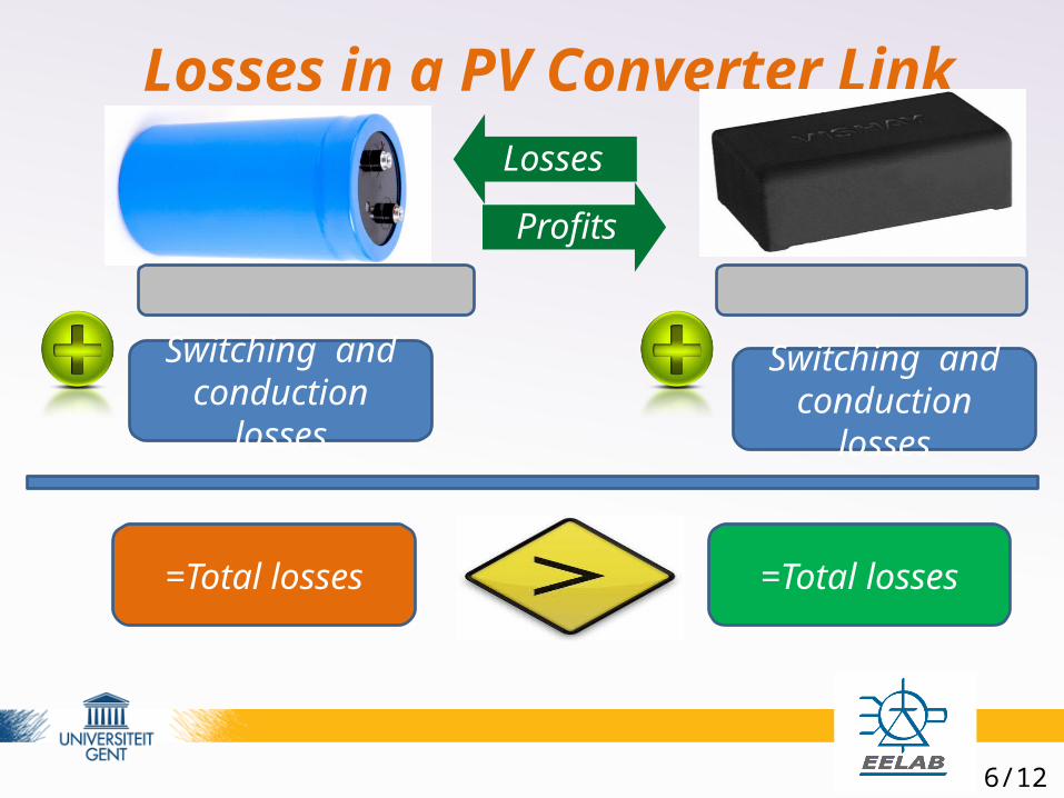
Losses in a PV Converter LinkLosses
Profits
Capacitors losses Capacitor losses
Switching and conduction losses
Switching and conduction losses
=Total losses =Total losses

7/12
Current control
t0
Ip
Toff Toff
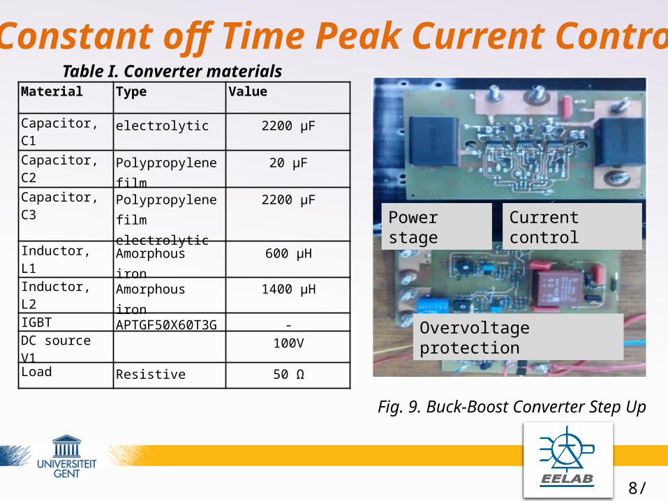
Fig. 4. Constant off Time Peak Current Control
Constant off time peak current control” (COPCC): protection and control combined
Current control at constant frequency: Instability @ 50% duty cycle
8/12
Material Type Value
Capacitor, C1 electrolytic 2200 µF
Capacitor, C2 Polypropylene film 20 µF
Capacitor, C3 Polypropylene filmelectrolytic
2200 µF
Inductor, L1 Amorphous iron 600 µH
Inductor, L2 Amorphous iron 1400 µH
IGBT APTGF50X60T3G -DC source V1 100V
Load Resistive 50 Ω
Constant off Time Peak Current Control
Power stage Current control
Overvoltage protection
Fig. 9. Buck-Boost Converter Step Up
Table I. Converter materials

9/12
0.027 0.028 0.029 0.03 0.031 0.032 0.033 0.0341
2
3
4
5
6
7
8
Time[seconds]
Var
iabl
es
Vc2
IL1
Iref
0.047 0.048 0.049 0.05 0.051 0.052 0.053 0.0542
3
4
5
6
7
8
Time[seconds]
Var
iabl
es
Vc2
IL1
Iref
Simulation and Lab experment work
Fig. 8 &10. Constant Off time Peak Current Control without HP feedback
Fig. 9 &11. Constant Off time Peak Current Control with HP feedback
Distortion frequencies
No distortion frequencies (Fig.9 &11)
COPCC with HP filter:
+ fast and protection included
- not easy for DSP or µcontroller

10/12
Current control with High pass filter feedback
Continuous
pow ergui
c3c2c1
v+-
v +-
To
V2V1
Signal 1
In<Lo> S/H>=
PID
PID
g DS
Lf2Lf1
L2L1
du/dt
i+ -i+ -
-C-
Cf2
Cf1
Fig.13. The PV converter current mode control block diagram

11/12
Simulation results
0.064 0.066 0.068 0.07 0.072 0.074 0.0762
2.5
3
3.5
4
4.5
5
5.5
6
Time[seconds]
Cur
rent
IL2
Iref
0.008 0.01 0.012 0.014 0.016 0.018 0.022
2.5
3
3.5
4
4.5
5
5.5
6
Time[seconds]
Cur
rent
IL2
Iref
Fig.14. Iref and IL2 of the Boost converter
Fig.14. Iref and IL2 of the Boost converter
COPCC with second order HP filter:+ fast and protection included
- Possible for DSP or µcontroller

12/12
Conclusions
Cost effective
PV system
Polypropylene Capacitors
in DC link
Topology in Fig.1
Current Control with HPF makes
the grid stable

13/12
Questions

14/11
References[1] S. Michael and B. Joe “Selecting Film Bus Link Capacitors for High Performance Inverter Applications,” Electronic Concepts Inc. Eatontown, NJ 07724[2] M.H. Bierhoff, F.W. Fuchs, “Semiconductor Losses in Voltage Source and Current Source IGBT Converters Based on Analytical Derivation,” [3] http://www.digikey.com/product-detail/en/APTGF50X60T3G/APTGF50X60T3G-ND/1920455[4] Lucas Laursen, “Production of Solar Panels Outpaced Investment Last year”, 1 Oct 2013.http://spectrum.ieee.org/energywise/energy/renewables/production-of-solar-panels-outpaced-investments-last-year[5] Rajendra Aparnathi and Ved Yvas Dwived, “LCL Filter for three Phase Stable Inverter Using Active Damping Method (Genetic Algorithm)”,[6] Antonio Coccia, “Control Method for Single-Phase Grid Connected LCL Inverter”[7] Daniel Wojciechowski, “Unified LCL Circuit for Modular Active Power filter”, International Journal for Computation and Mathematics in Electrical and Electronics Engineering,Vol.31 Iss:6,pp.1985-1997.[8] Jian Li, “Current-Mode Control: Modeling and its Digital Application”, Blacksburg, Virginia, 2009[9] Alex Van den Bossche, Dimitar Vaskov B.,Thomas V, and Vencislav Cekov V., “Programmable Logic Based Brushless DC Motor Control” EPE 2011-Birmingham