Embed Size (px)
Citation preview
AC 2011-784: REDISCOVERING RECIPROCATING STEAM
Matthew A. Carr, U.S. Naval Academy
Commander, US Navy PhD, PE Permanent Military Professor Nuclear Submarine Officer Member - TheNewcomen Society for the History of Engineering and Technology
c©American Society for Engineering Education, 2011
Page 22.1227.1

Rediscovering Reciprocating Steam A Fresh Look at Historical Steam Power
(Reciprocating Steam 101) introduction The purposes of this article are: (1) to describe the most significant steam engines from the early period of steam power, concentrating on the pumping engines of Thomas Savery, Thomas Newcomen, and James Watt; (2) to discuss thermo-fluids analyses of these engines based upon authentic historical data; and, (3) to encourage including this amazing history in the teaching of thermodynamics and fluid mechanics. Modern treatment of undergraduate thermodynamics tends toward superficial acknowledgement of the role of reciprocating steam engines in the development of power systems. Many thermo textbooks recognize James Watt as a significant inventor of steam engine technology, but totally overlook his significant predecessors, the most notable successful examples being Thomas Savery and Thomas Newcomen. Newcomen built successful machines over fifty years before James Watt made his world-altering developments to the steam engine. Watt’s genius is impressive, but it was his analysis of a model Newcomen engine (while attempting to repair it) that gave him his start in the steam engine business. Reciprocating steam engines enabled the industrial revolution and were dominant for about 200 years. And it took an additional half century to transition from virtually all steam engines being reciprocators to the point that steam turbines prevailed. Reciprocating steam engines currently operating in industrialized nations may largely be relegated to nostalgic restorations of antique traction engines at farm shows, steam locomotives on tourist railroads, miscellaneous museum pieces, and toys and models of various complexities. However the rugged and long life span of reciprocating steam engines means that they remain more commonly used in many post-colonial third world nations. In the United States and other developed countries, there are numerous hobbyists and aficionados who have been captivated by reciprocating steam mechanics and restore old engines, and even build new ones. Today’s engineering students can benefit from a greater appreciation of the operating principles of these historic engines and exercise solid engineering fundamentals in the process of analyzing them. Many will find the historical development of technology to be very interesting and this interest can be motivating and contribute to the learning process. methodology There are many books that are currently out of print that provide historical perspective on development of the steam engine. These books provide well-researched insights into the inventors and the operating principles of their machines. Due to the development of the concepts that were later to be formalized into terms such as energy, work and heat, efficiency, and absolute and gage pressures, documents written contemporary to the construction of these early engines did not have a consistent or thorough way of measuring their performance. The fact that the early engines were used predominately for pumping water, the contemporary accounts tended to report data on water pumped and some details about the dimensions of the engine and pipe elevations, but they often left out information that we can use today to calculate steam parameters and efficiency. There is some data, but not very uniformly reported. The author has searched sources written on this topic
Page 22.1227.2

spanning the late 19th and into the mid-20th Centuries and has attempted to associate more complete operating data with specific machines. Literature searches of more recent journal articles did not yield any additional data on these early engines. Where data was available, it is reported and analyzed. Where data may be inferred and estimated, the author has discussed the logic and illustrated the techniques. With respect to the types of analyses shown in this article, the author has attempted to use a variety of modern thermal-fluids analytical methods. When analyzing a heat engine used for pumping water, there are a number of energy conversions, each with non-unity efficiency. This is shown graphically in Figure 1, below.
Figure 1 - Pumping Engine Efficiency Relationships
The notation convention used herein is that “dotted” terms indicate the time rate of the extensive variable. The fuel energy rate ( E& ) is the product of the mass flow rate of the fuel ( ) and its heating value (HV). The engine has a thermodynamic efficiency (ηthermal) that satisfies the Second Law of Thermodynamics and accounts for non-adiabatic heat and non-isentropic work processes in the cycle of the working fluid. The engine mechanical efficiency (ηeng mech) more directly accounts for the friction in the engine. These two efficiencies can be grouped to form the engine overall efficiency. All blocks taken together describe the system overall efficiency. Figure 1 is a general concept sketch that can be adapted to various configurations. For instance, the Savery pumping engine, which will be described below, integrates the pumping action in the same chamber where the steam thermodynamics takes place. As a result, it would be appropriate to remove the engine mechanical efficiency block from Figure 1 for a Savery pump.
m&
When considering the performance of historic pumping engines, steam cylinder geometry is often given. Sometimes the number of strokes and the water production rate is available. Sometimes the water production rate may be calculated knowing the pump geometry and the stroke rate. These combinations of data typically allow calculation of the power delivered in the water produced. Indicated work or power can be determined upon the occasion when the in-cylinder mean pressure or a p-v indicator diagram is available. In conducting this research, the author has not found data that would allow calculation of brake power for these engines. When the boiler fuel consumption rate is available with the water production rate, then the efficiency of the overall system can be calculated. A note about units. The Savery, Newcomen, and Watt engines were developed in a time of British Imperial Units. These are slightly different from the United States Customary System (USCS) of units and the unique conversion factors are highlighted herein. Out of deference to these original units and the fact that the vast majority of engineers practicing engineering in the United States
Page 22.1227.3

continue to use “English” units, the analyses of this paper continues their use. Brackets {} are used to highlight conversion factors introduced into the equations. background By the late-17th Century, mineral extraction by mining had progressed below the land surface to the point that groundwater impeded access to mineral veins, especially in the wet climate of northern Europe. Both reciprocating suction and reciprocating plunger pumps already existed. This basic technology had existed for millennia, but to this point in time, these pumps were driven by human, animal, wind, or water power. The situation in the mining industry called for more effective and less-costly means of dewatering mines. A number of inventors applied themselves to this challenge. Two areas of the Enlightenment period that influenced this situation were the development of scientific societies and the reformation of patent laws. The formation of scientific societies in the 17th Century and their correspondence aided in the communication of the concepts and experiments conducted, much like today’s journals. The scientists of the day were referred to as “philosophers.” In this arena, names that should be familiar to our students, but often without context are Galileo Galilei, Evangelista Torricelli, Blaise Pascal, Robert Boyle, and Robert Hooke. Not so familiar will be Cosmo de Medici, Christiaan Huygens, Denis Papin, and Otto von Guericke. These men all had a part in the development of our understanding of the applicable physical science and technology. Their biographies and discussion of their contributions are available on line, but there is insufficient room to discuss them further here. In the patent arena, laws were changed from establishing monopolies for providing goods to rewarding inventors whose devices benefited society. The prospect of royalties for patented things provided additional incentives for research and development. Communication of scientific understanding and financial reward for practical solutions to problems both played out in the development of the steam engine. Some of the significant concepts that led to the steam engine were that the atmosphere has weight; weight is a force; force distributed over an area is pressure and its corollary, pressure on an area creates a force; gases are elastic; fluid pressure less than atmospheric defines a vacuum; boiling water creates steam that has a much lower density and much higher energy than liquid water; condensing steam in a closed chamber lowers the pressure and can create a vacuum; and steam, like other gases, is elastic. With respect to pumping water, the recognition that water could be drawn up a pipe by suction, but was limited to about 28 feet (this was later increased by better seals on the pumps, but overall limited to almost 34 feet) was a significant concept. The earliest practical water pumping steam engines were designed in Great Britain. As with many technologies, numerous individuals contributed incrementally to achieve our current understanding. The development of these engines passed through a period of “atmospheric” and low pressure steam engines. These atmospheric engines used steam to set the cycle and then condensed the steam to create a vacuum. The working “stroke” was accomplished by atmospheric pressure working against the vacuum achieved. With improvement in materials and machining capabilities, it became possible to operate pistons with pressures increasingly above atmospheric.
Page 22.1227.4

the Savery pump Thomas Savery (c1650-1715), building on the work of the earlier philosophers and experimenters who discovered atmospheric pressure, vacuum conditions, steam characteristics, and the relationships of pressure, area and force, designed the first practical pumping engine. Savery was issued a patent for his pumping engine in 1698. His engine is shown in Figure 2. The principle components were a “receiver” (R) connected to a suction pipe with a check valve (SV) and a discharge pipe (DP) also with a check valve (DV) installed. The receiver was connected to a boiler (B) via a steam pipe (SP) and steam control valve (SC). Another valve off the discharge pipe, the condensing jet valve (CJ), allowed some of the water to drain from the discharge pipe and flow around the receiver. Savery’s system operated first by filling the receiver with steam and then by condensing the steam to create a vacuum in the receiver. The difference between atmospheric pressure at the mine water (MW) level and the receiver’s vacuum pushed water into the receiver. Subsequent admission of steam at elevated pressure then pushed the receiver’s contents up and out through the discharge pipe. The cycle was repeated.
Figure 2 - Savery's Engine, 1698 1
Savery erected an engine in London in or about 1702 as a sales demonstrator with the general configuration shown in Figure 2. This engine had 16 foot suction pipe and a “rising main” of 42 feet. The boiler was “globular” in shape. The bottle-shaped receiver held 13 gallons of water and the operating cycle could be repeated four times per minute.2 The dimensions of the receiver are not known and likely drew in and discharged the 13 gallons of liquid water on each cycle, but would have had a larger overall volume. Thus, this engine raised a net 52 gallons of water 58 feet per minute (allowing for some water to be used for the “condensing jet” and then drained back to the mine level). The valves and pipes were made of brass and the boiler and receiver were of beaten copper.3 No data was found for the coal consumption or boiler operating pressure for this specific engine, but the minimum boiler operating pressure can be estimated. Let’s first estimate the power of this pump. Start the analysis with the Steady Flow Energy Equation (SFEE). Ignoring any temperature rise in the water due to contact with the steam, the
Page 22.1227.5

density (ρ) of water is 62.4 lbm/ft3, internal energy (u) does not change, and we’ll ignore the heat transfer (q12). Note that ρ of water can be calculated from the Steam Tables as the inverse of the specific volume, ρ = 1 / v. The 62.4 value for ρ is for cold fresh water and is accurate for room temperature and colder conditions (there is less than 5% error with liquid temperatures slightly over 200 oF). The SFEE is:
12222
22
212111
21
1 22wuvp
gvz
ggquvp
gvz
gg
cccc
+++⎟⎟⎠
⎞⎜⎜⎝
⎛+⎟⎟
⎠
⎞⎜⎜⎝
⎛=+++⎟⎟
⎠
⎞⎜⎜⎝
⎛+⎟⎟
⎠
⎞⎜⎜⎝
⎛ vv
State point 1 (SP1) is chosen at the suction inlet, approximately at standard atmospheric pressure; SP2 is at the discharge of the riser main, 58 feet higher. We don’t know the pipe diameters, but let’s assume that they are the same diameter, so the velocities will be the same going in and out. Rearranging and introducing the mass flow rate ( ), m&
( ) {
⎪⎪⎭
⎪⎪⎬
⎫
⎪⎪⎩
⎪⎪⎨
⎧
+−+−
+⎟⎟⎠
⎞⎜⎜⎝
⎛ −+−⎟⎟
⎠
⎞⎜⎜⎝
⎛==
01221
2122
21
21 2quupp
gvvzz
ggmwmW
CancelsCancelsCancels
cc321
4342143421
vv&&&
ρ
We can solve for the mass flow rate and then substitute. Note that g/gc accomplishes the unit conversion from lbm to lbf. There are 7.48 gallons in a cubic foot and 1 hp = 33,000 ft-lbf/min.
( )( ){ } min48448.71min584.62 33 lbmgalftgalftlbmVm === && ρ
( ) ( ) ( ) ft
slbflbmft
sft
lbmzzggmwmW
c
5802.32
2.32min484
2
2
21 −
⎪⎪⎭
⎪⎪⎬
⎫
⎪⎪⎩
⎪⎪⎨
⎧
⋅⋅
=−⎭⎬⎫
⎩⎨⎧
== &&&
( ){ } hplbffthplbfftW 85.0000,33min1min072,28 −=⋅⋅⋅−=& Savery’s sales demonstrator pump delivered slightly less than 1 hp. The negative sign is consistent with work “in” to the fluid. To estimate the boiler pressure requirement, the boiler had to expel water 42 feet, not the entire 58 feet of lift height. Without knowing any specific details of the pipe size and, therefore, the velocity, we can nonetheless use the familiar hydrostatic equation to estimate the boiler pressure to expel the water from the receiver.
( )( )( ){ } )(7.141441424.62 2223 absinlbfinftftlbmlbfftlbmphggp atm
c
+=+= ρ
psiapsiapsip 9.327.142.18 =+= The boiler had to exceed 33 psia to expel the water from this receiver. Note that this is about 18 psig. Referring to a set of Steam Tables, the boiler operated in saturated conditions, therefore the
Page 22.1227.6

boiler temperature was approximately 256 oF.4 Contemporary reports describe Savery’s boilers could “make steam eight or ten times stronger than common air.”5 This places the steam pressure in the range of 117 to 147 psi gage. Taking the lower number and assuming the pressure was 100 psig to allow for pipe friction (“major” losses) and valve & fitting resistance (“minor” losses) to fluid flow, the height above the receiver that the water could be ejected would be:
ftftin
sft
slbflbmft
ftlbminlbf
ggpz c 230144
2.32
2.32
4.62
1002
2
2
2
3
2=
⎭⎬⎫
⎩⎨⎧
⎪⎪⎭
⎪⎪⎬
⎫
⎪⎪⎩
⎪⎪⎨
⎧⋅⋅
⎟⎟⎟⎟
⎠
⎞
⎜⎜⎜⎜
⎝
⎛
=Δ
=Δρ
Taking the approximately 10 bar highest pressure listed (approximately 160 psia), the boiler temperature would have been about 364 oF. Note that this was done with a copper boiler and would have required solder that could withstand this combination of pressure and temperature. And, Savery reportedly did not use a pressure relief valve!6 John Smeaton (1724-1792) was an 18th century engineer who made systematic studies of the performance of existing engines. Smeaton modeled engines to better understand them and developed numerous enhancements to these engines. Smeaton’s records provide data that can be calculated by today’s students. He measured the performance of a Savery pumping engine in 1774. This engine was bigger than the sales model described above. The receiver in the tested engine was 16 inches in diameter and 22 feet high. The pump raised water only 14 feet, made 12 strokes per minute and discharged 100 cubic feet of water per minute. The coal consumption was 3 centum weights (cwt) in four hours.7 Note that the British imperial units are different than the comparable American system. A cwt is 100 pounds in the American system; a cwt is 112 pounds in the imperial system of measure. This data allows estimation of the efficiency of a Savery pump. On a per minute basis, the work (W) of raising the water is:
zggVz
ggmdFW
cc
Δ=Δ⎟⎟⎠
⎞⎜⎜⎝
⎛=×= ρ
( ) ( ) lbfftftlbmlbfft
ftlbmz
ggVW
c
⋅=⎭⎬⎫
⎩⎨⎧
⎟⎟⎠
⎞⎜⎜⎝
⎛=Δ= 360,8714
111004.62 3
3ρ
A note about British coal. The majority of coal produced in Britain was and is bituminous coal which has a heating value ranging from 10,000 to 14,000 Btu/lbm. The average heating value of coal in the UK is about 10,750 Btu/lbm.8 For our purposes, discussion of higher versus lower heating values is not needed, so long as the same value is used in the calculations. Assuming an average heating value (HV) for coal at 10,750 Btu/lbm, the heat energy (E) added to the boiler for this engine on a per minute basis is:
Page 22.1227.7

( )⎭⎬⎫
⎩⎨⎧ ⋅⎟⎠⎞
⎜⎝⎛=⎟
⎟
⎠
⎞
⎜⎜
⎝
⎛
⋅
⋅⎟⎠⎞
⎜⎝⎛==
BtulbfftBtu
hrhrscwt
lbmcwt
lbmBtu
tmHVE 778
min050,15min604
1123750,10
&&
lbfftEE ⋅= 67.11 The system overall efficiency (ηoverall system), then, is:
%8.00075.0717.1474.8
≅=⋅⋅
==lbfftElbfftE
inputoutput
systemoverallη
The Savery pump system overall efficiency was about 0.8%. In other words, for every 100 pounds of fuel used to run the engine, the energy from 99.2 pounds was wasted! The description by Smeaton is suitable for other analyses by today’s students. Hydrostatics governs the height limitation of the receiver above the source water level. Assuming a perfect vacuum, the maximum height of the receiver water level above the source water level would be:
ftftin
sft
ftlbm
slbflbmft
inlbf
ggpzz
ggp c
c
9.331442.324.62
2.327.14 2
2
23
2
2 =⎭⎬⎫
⎩⎨⎧
⎟⎟⎟⎟
⎠
⎞
⎜⎜⎜⎜
⎝
⎛⋅⋅
⎟⎠⎞
⎜⎝⎛=Δ=Δ⇒Δ=Δ
ρρ
Assuming hemispherical end caps on this receiver, the receiver volume is approximately:
434 23
cylindercylindersphere
LDrVVVππ
+=+=
{ }{ } 3
2
3
1.304
7.2012
16
/128
34 ft
ftftin
in
ftininV =
⎟⎟⎠
⎞⎜⎜⎝
⎛
+⎟⎟⎠
⎞⎜⎜⎝
⎛=
ππ
If the receiver produced 100 ft3 in 12 strokes, then each stroke yielded 8.3 ft3 (62 gallons) or about 25% of the receiver’s volume. As the water was drawn in, the steam would be expected to lose vacuum and the water would heat up. For additional Steam Tables practice, assume that this receiver was at thermal equilibrium and filled with 100 psia dry saturated steam and then condensed as an isolated system. Let’s calculate: (1) the mass of steam contained in the receiver; (2) the vacuum that could be achieved if the receiver were cooled to 125 oF; (3) the quality of the steam at the end of the condensing process; and, (4) the heat transferred from the steam to get it to that point. Referring to the Steam Tables, Tsat (100 psia) = 327.82 oF; vg (100 psia) = 4.431 ft3/lbm. Then the receiver of the volume already calculated, the total mass of steam is determined using the definition of specific volume.
Page 22.1227.8

vVmmVv // =⇒=
lbm
lbmftft
vVmsteam 79.6
431.4
1.303
3
===
Without any losses due to condensation during the steam admission process, one stroke would require 6.8 lbm of steam without any losses. If this receiver were cooled down all the way to 125 oF with no in-leakage, then the pressure in the receiver would be psat (125oF) = 1.94 psia. Assuming standard atmospheric pressure, this is a vacuum as measured by a mercury-filled manometer of:
psivppp absolutereceiveratmvacreceiver 8.129.17.14,, =−=−=
Hginpsia
Hginpsivp vacreceiver −=⎭⎬⎫
⎩⎨⎧ −
= 1.267.14
92.298.12,
The process between SP1 and SP2 is constant volume (also known as isometric or isochoric), therefore v1 = v2. The quality (x) of the steam in the receiver after it cools down is:
( ) %5.20247.0/66.178
/01623.0431.4)125(
)125(3
32
2 ≅=−
=−
=lbmft
lbmftFv
Fvvx o
fg
of
So, out of the original 100% steam in the receiver, only 2.5% remains as steam. This is a closed system, so the appropriate energy equation is the Non-Flow Energy Equation (NFEE), . With a fixed volume, there is no boundary work, so w12 = 0. We’re analyzing the steam and ignoring the energy contained in the copper receiver. Therefore
. Students may attempt to use the constant specific heat methodology to calculate the change in u. Since the fluid is undergoing a condensation process, this is not appropriate. Steam Tables provide the data.
122121 wuqu +=+
1212 uuq −=
At SP1:
u1 = ug (100 psia) = 1105.8 Btu/lbm.
At SP2:
( )( ) lbmBtulbmBtulbmBtuFuxFuu ofg
of /9.118/5.958025.0/98.94)125()125( 22 =+=+=
Then, the heat transferred is: lbmBtuuuq /8.9868.11059.1181212 −=−=−=
Page 22.1227.9

Note that the negative sign indicates that heat is removed from the steam. We had 6.8 lbm of steam in the isolated receiver, therefore:
Q12 = (q12)(m) = (-986.8Btu/lbm)(6.8lbm) = 6,710.6 Btu 6,710.6 Btu of heat was removed from the steam in condensing it to SP2 conditions. Recognize from a calculation above, that 2.3 feet of water in elevation produces 1 psi hydrostatic pressure. Contemporary reports indicated that the base of Savery’s receiver had to be within about 20 feet of the mine water level. A 22 foot high receiver about 25% full would have to have its interior water level below elevation 25 feet above the source water level in order to draw the mine water into the receiver. The postulated problem above is within the realm of reasonability. The causes of the low efficiency of a Savery engine were:
1. A primitive boiler with significant heat loss up the smoke stack. 2. Condensation of the incoming steam due to contact with the water being expelled. 3. The alternate heating and cooling of the metal receiver.
a. Loss of heat from the steam to the cold surface of the receiver. b. Extra condensing water was needed to cool down the receiver after the expulsion phase.
4. Loss of steam due to not allowing the steam to expand inside the receiver. Later improvements to Savery’s basic design provided dual receivers so that the vacuum and steam pressurization alternated between the two receivers and doubled the pumping rate. Likewise, a second boiler was added to the improved design. This second boiler operated at higher pressure than the main boiler and had a pipe inlet below the water level of the second boiler. It was run to inject batches of water into the operating, main boiler. This system eliminated the need to shut down and depressurize the main boiler to refill it and also served as a feedwater heater. The condensing process was also modified in later variants to include spraying water into the receiver instead of flowing water around the outside of the receiver. In the final analysis, the Savery engine did not prove very practical for pumping water from deep mines. Its success was largely in providing water for some towns and manor homes that included indoor running water and decorative fountains.9 the Newcomen pump One of the philosophers contemporary with Savery who developed precursor concepts and configurations for the advancement of the steam engine was Denis Papin (1647-1712?). In 1690, Papin built a device that moved a piston in a cylinder by boiling water inside the cylinder. The piston was latched in its raised position and the steam was then allowed to condense, thereby creating a vacuum. When the latch was released, the pressure of the atmosphere applied against the vacuum in the cylinder would move the piston. Papin recognized the state of the art of machining in his day limited what he could achieve. He expressed difficulty in “finding a workshop capable of easily making very large tubes.”10 As a result, a functional engine utilizing a piston and cylinder configuration was left to another to develop.
Page 22.1227.10

Thomas Newcomen (1663-1729) invented the first practical piston and cylinder engine by connecting a piston to one end of a rocking beam that was connected on its other end to a separate reciprocating pump. Newcomen designed his pump around 1705, but the first one built was in 1712. Figure 3 shows Newcomen’s 1712 engine.
Figure 3 - Newcomen's Engine, 1712 11
Newcomen’s design raised the piston (P) using steam in a “non-work” reset stroke. The main pump (MP) side of the beam was closely balanced so that the engine required steam pressure at or just slightly above atmospheric in order to raise the piston. The cycle commenced with the piston at top dead center and the cylinder full of steam. In the developmental configuration, water was sprayed onto the outside of the cylinder to create a vacuum, similar to Savery’s receiver. The resulting slow condensing process limited the number of strokes per minute. So, Newcomen soon thereafter adopted a jet condensing process in which water from the cold water tank (CWT) was sprayed directly into the cylinder (C) to condense the steam. This about doubled the rate of operation. The atmospheric pressure on the top of the piston being greater than the vacuum below, the piston was pushed down in the work stroke. Steam was then admitted to the cylinder from the boiler to reset the cycle. Liquid water was drained and gases in the cylinder were bubbled out via the feedwater tank (FWT). The piston incorporated a water-aided seal, hence the pipe to supply sealing water via the water tap (WT). Early cylinders were of brass, but cast iron began to be used soon thereafter. After about 1743, essentially all cylinders were made from cast iron. Cast iron cylinders could be manufactured thinner and consequently had a lower heat capacity than those of brass.12 Due to the expansive wording of Savery’s patent for “Raising water by the impellent force of fire,” Newcomen was forced to partner with Savery in order to produce his engine, the first of which was built in 1712. After Savery died in 1715, his patent was purchased by a group of “proprietors.” Newcomen’s pumping engine was a significant improvement over Savery’s pump that earned royalty payments for both Newcomen and the Proprietors. In the space of twenty years, about 100 Newcomen engines were built (during a period that preceded the industrial revolution) and over 1000 had been built by the year 1800.13 Because of their simplicity, Newcomen and similar atmospheric engines continued to operate simultaneously with the later-developed Watt engines for
Page 22.1227.11

well over a century. The last Newcomen engine in operation was used until about 1930. The growth of steam power is shown in Figure 4.
Figure 4 - Growth of Steam Power in the 18th Century14
Newcomen’s 1712 engine used a brass cylinder 7 ft 10 inches high and 21 inches in diameter. A contemporary description of the engine stated “Vibrates 12 times in a Minute & each stroke lifts 10 Gall. of water 51 yards p’pendr.”15 Using this information, we can calculate the power of this pumping system.
( )zgg
tVz
gg
tmwmW
cc
Δ⎟⎟⎠
⎞⎜⎜⎝
⎛=Δ== ρ&&
( )min
163,15335111
min12
48.71104.62
3
3lbfft
ydftyards
lbmlbfstrokes
galft
strokegal
ftlbmW ⋅
=⎭⎬⎫
⎩⎨⎧
⎭⎬⎫
⎩⎨⎧⎟⎠⎞
⎜⎝⎛
⎭⎬⎫
⎩⎨⎧⎟⎠⎞
⎜⎝⎛⎟⎟⎠
⎞⎜⎜⎝
⎛=&
hplbfft
hplbfftW 6.4min/000,33
1min
163,153 =⎭⎬⎫
⎩⎨⎧
⋅⎟⎠⎞
⎜⎝⎛ ⋅
=&
Smeaton defined the “great product” of a pumping engine based upon the number of pounds of water (in millions) raised one foot while the boiler consumed one bushel of coal.16 The term evolved to “duty.” This is analogous to a current motor vehicle’s measurement of “efficiency” in miles per gallon. Smeaton’s methodology normalized the performance of various engines, which facilitated comparison.17 He obtained performance data for fifteen Newcomen engines and determined that the average duty of these engines was 5.59 and the average pressure on the piston was 6.72 psi.18 Using the same energy content in coal as used in the Savery pump analyses, the efficiency of these Newcomen engines was:
( )( ){ } %8.0008.0778750,1084
659.5==
⋅⋅
==BtulbfftlbmBtubushellbm
bushellbfftEE
W
in
outη
Page 22.1227.12
Early Newcomen engines were no more efficient than Savery’s, but they were much more reliable and, since they used positive displacement pumps, were capable of pumping from much greater depths. Reliability explains their growth as shown in Figure 4. Smeaton, however, improved upon the Newcomen engine by studying the cylinder bore, piston stroke, and the operating pressure. He also had improved cylinder machining and piston seals available by his time which made a significant difference in the capability of later pistons and cylinders. He is credited with achieving the highest performance of a Newcomen engine. Smeaton’s Long Benton colliery engine, erected in 1774, had a cylinder bore of 52 inches and a stroke of 7 feet. The engine made 12 ½ strokes per minute with a mean pressure of 7 ½ psi vacuum and produced a “duty” of 9.45 million pounds of water raised one foot per bushel of coal consumed.19 Note that this was a bit higher pressure than average for the earlier Newcomen pumps. Therefore, the duty was improved to:
( )( ){ } %4.10135.0778750,1084
645.9≅=
⋅⋅
==BtulbfftlbmBtubushellbm
bushellbfftEE
W
in
outη
Note that the Newcomen engine’s overall efficiency as improved by Smeaton, while miserably low by current state of the art, was almost twice as efficient as Savery’s. This was a substantial improvement in fuel consumption for the same pumping performance. The given information allows calculation of the power output of the piston. At 12 ½ strokes per minute, one stroke takes 0.08 minutes, or 4.8 seconds.
tdDp
tdpA
tdFW
4
2 ×=
×=
×=
π&
( ){ } ( ) ( )( ) min
64.1min/08.04
712521445.7 22222 lbfftEstroke
strokeftftftininlbfW ⋅==
π&
hplbfft
hplbfftEW 2.42min000,33
1min
64.1 =⋅
⎟⎠⎞
⎜⎝⎛ ⋅
=&
The moving parts of the Long Benton engine weighed 8 ½ tons.20 That is a lot of weight per horsepower delivered, especially considering today’s engines. An indicator diagram is a p-v diagram that was produced by a mechanical device that connected to the piston’s connecting rod and to a pressure tap to the cylinder. The device produced a tracing of the pressure versus the piston position which could be scaled to volume inside the piston/cylinder. An indicator card was recorded in 1895 on a Newcomen engine with a cylinder of 5’6” diameter and 6’ stroke. The result is shown in Figure 5. The engine went through 10 strokes per minute and the boiler pressure was 2.3 psi. Note that the cylinder pressure recorded above the atmospheric line was less than 1 psig, so there were some pressure losses in the pipes and valves between the boiler and the cylinder.
Page 22.1227.13
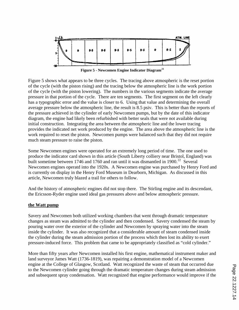
Figure 5 - Newcomen Engine Indicator Diagram21
Figure 5 shows what appears to be three cycles. The tracing above atmospheric is the reset portion of the cycle (with the piston rising) and the tracing below the atmospheric line is the work portion of the cycle (with the piston lowering). The numbers in the various segments indicate the average pressure in that portion of the cycle. There are ten segments. The first segment on the left clearly has a typographic error and the value is closer to 6. Using that value and determining the overall average pressure below the atmospheric line, the result is 8.5 psiv. This is better than the reports of the pressure achieved in the cylinder of early Newcomen pumps, but by the date of this indicator diagram, the engine had likely been refurbished with better seals that were not available during initial construction. Integrating the area between the atmospheric line and the lower tracing provides the indicated net work produced by the engine. The area above the atmospheric line is the work required to reset the piston. Newcomen pumps were balanced such that they did not require much steam pressure to raise the piston. Some Newcomen engines were operated for an extremely long period of time. The one used to produce the indicator card shown in this article (South Liberty colliery near Bristol, England) was built sometime between 1746 and 1760 and ran until it was dismantled in 1900.22 Several Newcomen engines operatd into the 1920s. A Newcomen engine was purchased by Henry Ford and is currently on display in the Henry Ford Museum in Dearborn, Michigan. As discussed in this article, Newcomen truly blazed a trail for others to follow. And the history of atmospheric engines did not stop there. The Stirling engine and its descendant, the Ericsson-Ryder engine used ideal gas pressures above and below atmospheric pressure. the Watt pump Savery and Newcomen both utilized working chambers that went through dramatic temperature changes as steam was admitted to the cylinder and then condensed. Savery condensed the steam by pouring water over the exterior of the cylinder and Newcomen by spraying water into the steam inside the cylinder. It was also recognized that a considerable amount of steam condensed inside the cylinder during the steam admission portion of the process which then lost its ability to exert pressure-induced force. This problem that came to be appropriately classified as “cold cylinder.” More than fifty years after Newcomen installed his first engine, mathematical instrument maker and land surveyor James Watt (1736-1819), was repairing a demonstration model of a Newcomen engine at the College of Glasgow, Scotland. Watt recognized the waste of steam that occurred due to the Newcomen cylinder going through the dramatic temperature changes during steam admission and subsequent spray condensation. Watt recognized that engine performance would improve if the
Page 22.1227.14

condensing operation took place in another chamber, thereby keeping the working cylinder hot. In 1765, he improved upon the Newcomen operating concept by designing a separate condenser vessel. Watt also introduced the use of a steam jacket around the engine cylinder to keep it hot. The major improvements are shown in Figure 6 and contrasted to the Newcomen configuration.
Figure 6 - Newcomen and Watt Engine Comparison23
His early drawings show a piston rod attached directly to the pump rod, but this configuration was not followed up. The earliest Watt engines continued to be atmospheric engines, in the same vein as Newcomen’s, and used a similar beam and arch configuration as the Newcomen pumps. The subsequent use of positive steam pressure to push the piston during the working stroke was a major innovation that was soon adopted by Watt, but required a fairly effective stuffing box seal around the piston rod.
Page 22.1227.15

Figure 7 - Watt's Single-Acting Pump Engine 178824
Watt’s engine cycle started with the piston at the top of its stroke. Steam entered via an equilibrium valve both above and below the piston. This warmed the parts and expelled air. The equilibrium valve was closed and water was sprayed into the condenser’s jet nozzle. This formed a vacuum which, together with the positive steam pressure above the piston, caused the working stroke. The steam and exhaust valves were closed and the equilibrium valve re-opened to supply steam and equalize the pressure above and below the piston. As with the Newcomen pump, the balancing of the pump, piston and beam caused the piston to rise due to gravity. The cycle was repeated. The first two strokes were operated manually. Then trips on the plug rod to the air pump controlled the valve sequencing. A noteworthy feature included an air pump operated by the rocking beam that drew non-condensable gases out of the condenser.25 Watt’s early engines worked on steam pressures similar to Newcomen’s. Pressures higher than about 7 psi above atmospheric were rarely used.26 This situation reflects the state of boiler strength to avoid rupture and the ability of gland seals and piston rings to minimize leakage. Watt described the performance of an engine at Wheal Butson in 1792. This engine had a 36 inch cylinder and a stroke of 8 feet. It pumped water up 50 fathoms and 2 feet using a 9 ½ inch bore pump. In 12 hours, the boiler consumed 17 bushels of coal and the pump made 7550 strokes.27 Let’s calculate the power and efficiency of this engine. The pump bore was a constant diameter throughout its pumping height. This allowed removal of the internals from the top of the well for maintenance. A fathom is 6 feet, so the total pumping height of this engine was 302 feet. Every stroke yielded:
Page 22.1227.16

galftin
ftftinLDV stroke 5.3094.3144
84
5.94
32
2222
==⎭⎬⎫
⎩⎨⎧
== ππ
The water produced by each stroke weighed:
lbflbmlbfft
ftlbm
ggVg
gmFcc
strokeperweight 9.2451194.34.62 3
3 =⎭⎬⎫
⎩⎨⎧=== ρ
It did this N times per minute:
min
5.1062912
7550 strokeshr
strokeshoursstrokesN ===
It took t = 12 hrs / 17 bushels = 0.71 hrs to burn one bushel of coal. This was 1.41 bushels per hour. This worked out to be 444 pump strokes per bushel of coal. The Duty of this engine then is:
( )coalofbushel
ftlbfmillionelevationftstroke
lbfbushelstrokesDuty ⋅
=⎟⎠⎞
⎜⎝⎛⎟⎠⎞
⎜⎝⎛= 0.333029.245444
Recall that the Newcomen pumps improved by Smeaton achieved about 9.45 million ft-pounds per bushel. The Watt engine was about 3 ½ times more efficient than the improved Newcomen pump. The weight of the water contained in the pump’s piping is quite impressive.
lbflbmlbf
inftftin
ftlbm
ggLD
ggVF
ccweight 9276
11
144302
45.94.62
4 2
222
3
2
=⎭⎬⎫
⎩⎨⎧
⎭⎬⎫
⎩⎨⎧
=⎟⎟⎠
⎞⎜⎜⎝
⎛== ππρρ
The pump had to lift that entire weight to eject the water out from the top of the pump. The power of this engine was:
hphrlbftf
hphr
bushelsbushel
lbfftt
WW 5.23min60
1min/000,33
141.1000,000,33 =⎭⎬⎫
⎩⎨⎧
⎭⎬⎫
⎩⎨⎧
⋅⎟⎠⎞
⎜⎝⎛⎟⎠⎞
⎜⎝⎛ ⋅
==&
&
The overall system efficiency, then, is:
( )( ){ } %7.40470.0778750,1084
60.33==
⋅⋅
==BtulbfftlbmBtubushellbm
bushellbfftEE
W
in
outη
As can be seen, Watt’s pumping engines were significantly more efficient than Newcomen’s, on the order of 5 times better. The highest demand for more efficient pumping was in the metal mining
Page 22.1227.17

area of Cornwall which was not near England’s coal producing regions. Transporting coal for atmospheric engines was a significant additional expense and Watt’s increase in efficiency provided ready customers. However, Newcomen engines persisted at coal mines well after Watt engines were introduced because they used waste coal that had very low value. It is worth noting that Watt was in partnership with English industrialist, Matthew Boulton. The firm of Boulton and Watt earned payments based upon a portion of the savings in fuel as compared to the Newcomen-type engines. All steam machinery that operates in a vacuum must deal with the in-leakage and the release of gases from solution in water. In Savery’s engine, non-condensables accumulated in the receiver. In Newcomen’s, these gases accumulated in the operating cylinder. These gases gradually reduced the operating performance to where the engines would just stop and require purging. These engines were adapted to this phenomenon by purging the receiver or cylinder during each operating cycle. This was accomplished by blowing the air out with steam. On Savery’s engine, the air exited with the water that was expelled from the receiver. On Newcomen’s engine it was expelled through a “snifting valve” into a water-filled container. The gases would bubble out and when the purging steam reached the container, it would condense and not bubble. This technique also increased steam consumption and reduced the overall energy efficiency, but was a cost of operation. Newcomen engines were adapted to time the purging and retain some gases in order to operate at partial loads. The interface of piston to cylinder is a compromise between effective seals to prevent leakage and excessive friction caused by the seals. Early boring and milling machinery was limited in its ability to create a cylinder of consistent circular cross-section and a matching, close fitting piston. Consequently, the early steam pistons incorporated either a leather flap and water seal on top of the piston or a rope seal. The rope seal technique is the predecessor of today’s piston rings. Leakage across the seals limited the pressure that could be applied to the early engines, just as much as the ability of the metallurgy of the day to contain the pressure in the boiler and piping. In using positive pressure to push the piston down, Watt is also credited with developing the concept of steam cutoff at mid-stroke and then allowing the steam to expand. He also developed the concept of using steam pressure to push the piston in both directions in what is referred to as double acting. Another desire for engine output was to produce rotating shaft power to run various mill operations. This was attempted on some Newcomen-type engines, but was mostly satisfied by both Savery and Newcomen engines pumping water up to a reservoir and then running the water through water wheels. This overall scheme included additional energy conversions, each with non-unity efficiency. Watt developed rotating shaft output engines in the 1780s. Watt’s plan to use a crankshaft was delayed until the expiration of a patent for use of this device in 1794. As a result, he developed and patented a double gear rotational drive in 1781. After 1794, the crankshaft and flywheel were generally used. incorporating historic engines into current instruction The graphics, description of operation, and calculations presented in this article were developed in view of making this article suitable to supplement typical undergraduate thermodynamics and fluid mechanics texts. Recognizing that many faculty members teaching these courses today have not
Page 22.1227.18

been exposed to these historic engines, additional background and context has been provided to help the instructor. Just acknowledging a significant milestone in engine development in class can provide interesting context for students, e.g. the Newcomen Engine turns 300 in the year 2012. However, the author encourages describing the basic operation and the appropriate characteristics of these engines in class. Then assign one or more of the analyses provided in this article as an in-class small group project, as a homework problem, or as a quiz or exam problem. Furthermore, the historical information presented in this article could also be a suitable topic for discussion at a meeting of any of the mechanical engineering clubs and honor societies (ASME, NSBE, Tau Beta Pi, Pi Tau Sigma, etc.). conclusions This article describes the operation and provides construction and archival operating data for the three most successful steam engine configurations of the 18th Century. Analyses using modern hand calculation techniques are presented. The overall efficiency of each of the engines is presented for comparison. A variety of calculation techniques are illustrated and span the topics of thermodynamics and fluid mechanics. The piston and cylinder engines discussed in this article, by modern standards, used very low pressure steam, and were stationary engines. The challenges of developing materials to contain higher pressures and seals to prevent piston bypass and system leakage were being developed during this nascent period. These developments ultimately allowed the steam engine to become the prime mover of the transportation sector, predominately in trains and ships and to some extent in trucks and automobiles. The year 2012 marks the 300th anniversary of the Newcomen pumping engine, the first truly successful steam engine. The Savery, Newcomen, and early Watt engines were used for pumping water from mines, pumping water to run mill water wheels, and for fountains at manor homes and town water supplies. Engines driving a rotating shaft came later in the progression. It is the hope of the author that today’s engineering students be enriched by being exposed to the legacy presented by these machines and that our students develop their engineering analytical skills by practicing the types of calculations illustrated in this article. Permission is granted to use the examples contained herein with or without attribution. Planned future articles will address rotational engines, the use of higher steam pressures; the benefits of steam cut-off, double acting, and compounding; and will show how to analyze these more complex systems. 1 Leask, A.R., Marine Engines, Simpkin Marshall & Co. Ltd., London, 1922, p.3. 2 Dickinson, H.W., A Short History of the Steam Engine, 2nd Ed, Frank Cass & Co. Ltd., London, 1963, p.25. 3 Rolt, L.T.C. and Allen, J.S., The Steam Engine of Thomas Newcomen, Science History Publications, New York, 1977, p.27.
Page 22.1227.19

4 1967 ASME Steam Tables. The 1967 Steam Tables are used throughout this article. Most textbooks currently in print refer to this version. The more recent recalculation published by ASME in 2006 does not differ dramatically from the earlier version and has not achieved the same degree of circulation. 5 Rolt, L.T.C., Thomas Newcomen - The Prehistory of the Steam Engine, Augustus M. Kelley, Publishers, New York, 1963, p.39. Comment attributed to Dr. Desaguliers in his Experimental Philosophy (1744). 6 Rolt & Allen, p.29. 7 Leask, pp.4f. 8 http://www.decc.gov.uk/en/content/cms/statistics/source/cv/cv.aspx, accessed 1/4/2010. The UK was a major coal producer throughout the period of the industrial revolution. This paper assumes that the coal composition of current coal extracted in the UK is similar to the coal used in the period of these engines. 9 Dickinson, Short History, p.27. 10 Dickinson, Short History, pp.8ff. 11 Leask, , p.7. 12 Thurston, R.H., A History of the Growth of the Steam Engine, Kegan Paul, Trench, Trubner & Co. Ltd., London, 1895, p.68. 13 Rolt & Allen, pp.144f. 14 Rolt & Allen, p.145. 15 Dickinson, Short History, pp.37f. 16 Rolt & Allen, p.112. 17 I.B. Hart, James Watt and the History of Steam Power, Henry Schuman Inc., New York, 1949, pp.148ff. 18 Dickinson, Short History, p.62. 19 Rolt, p.130. 20 Thurston, p.69. 21 Rolt & Allen, p.132. 22 Rolt, & Allen, p.134. 23 Dickinson, Short History, p.67. 24 Dickinson, Short History, p.76. 25 Dickinson, Short History, p.77. 26 Leask, p.10. 27 Dickinson, H.W., James Watt Craftsman & Engineer, Cambridge University Press, 1936, p.169.
Page 22.1227.20