Embed Size (px)
Citation preview
Research Journal of Engineering Sciences ___________________________________________ ISSN 2278 – 9472
Vol. 1(2), 15-25, August (2012) Res. J. Engineering Sci.
International Science Congress Association 15
Recycling of Bag-House Dust from Foundry Sand
Dugan B. and Anderson C. Center for Resource Recovery and Recycling, Kroll Institute for Extractive Metallurgy, Colorado School of Mines, COLORADO
Available online at: www.isca.in Received 10th June 2012, revised 15th June 2012, accepted 11th August 2012
Abstract
Non-metallic foundry waste is generally composed of spent green sand, core sand, and dust collected in the ventilation bag-
house systems of the foundry facility. Currently, practices exist for the recovery of sand particles from green sand and core
sand at the expense of the other constituents via combustion or degradation. However, new methods are necessary to extract
values other than sand from the bag-house dust material. This is important, because the dust of composed of as much as 50
weight percent non-sand recoverable materials, such as coal and clay. This research evaluates the potential to beneficiate
bag-house dust material by way of froth flotation. The coal constituent of the dust was extracted at grades near 60 weight
percent and recoveries near 70 weight percent. The clay constituent was extracted at grades near 30 weight percent and
recoveries near 40 weight percent.
Keywords: Froth flotation, green sand, coal, bentonite clay.
Introduction
Foundry green sand is composed of three basic components: a
refractory material, a binder, and an oxidation inhibitor. Most
commonly these components take the form of sand, clay, and
coal. While green sand is reusable, its three main components
are consumed or degraded with each use. This requires a
continuous addition of fresh materials into a foundry’s green
sand system and the removal of used green sand. The removed
green sand is typically discarded or used in some less critical
application.
When one considers that new green sand may cost as much as
0.04 to 0.14 dollars (US) per kilogram to produce, and tens of
dollars per ton to discard, there are serious economic
motivations for recovering valuable materials from the used
green sand1.
Processes are currently in use to recover sand grains from used
green sand by removing the coal and clay constituents from the
sand particle surfaces by way of thermal degradation and
surface abrasion2. The resultant sand particles, no longer
encapsulated by the other constituents, may then be sorted by
particle shape and size into more and less useful fractions,
which may then be recycled or discarded. This style of recovery
is very conducive to the recovery of sand from green sand, as
green sand is primarily composed of sand grains with other
materials present as minor fractions. However, this style of
recovery is much less effective for the recovery of values from
the dust fines generated in the bag-houses of foundry ventilation
systems. Due to the nature of the dust and its very fine particle
size, relative to green sand, the dust consists of a much larger
proportion of coal and clay material. Also, the very fine and
irregularly shaped sand particles present in the dust are not
desirable for most green sand systems. In juxtaposition to used
green sand recovery, dust recycling methods ought to focus on
the extraction and recovery of coal and clay values while
discarding the sand particles from the green sand system.
Material and Methods
Regarding flotation: Froth flotation has been selected as a
means of beneficiation because it is already a commonly applied
technique for extracting the targeted materials, coal and clay.
The basic practice of froth flotation is reliant upon physical
and/or chemical differences in surface characteristics between
the gangue material and the mineral, which will eventually
result in the hydrophobicity of either the gangue material or
mineral3. Froth flotation is conducted by mixing the feed
material with water and bubbling air through the slurry.
Hydrophobic materials attach to the bubbles and are carried to
the slurry surface where the material may be collected in a froth.
Some materials, like coal, maintain a naturally hydrophobic
surface characteristic while other materials may require
chemical reagents to modify their surface characteristics. For
instance, cationic collector reagents make use of the negatively
charged surfaces present on bentonite clay surfaces to physically
adsorb a hydrophobic hydrocarbon chain to the particle surface.
This is often referred to as “physisorption”4.
It is known from research done by Oats5
that the presence of
clay hinders coal flotation, as bentonite clay masks the
hydrophobic surface of coal. Bentonite, a commonly used clay
in green sand, is the specific clay addition present in this
investigated dust. It is hypothesized that this association and
interaction may be used to extract both materials from the bag-
house dust feed material.
Flotation practice: Experimentation for this work was
conducted in a bench scale Denver batch mechanical flotation
cell. The cell capacity is approximately 5 liters, agitates near
1400 rpm, and operates air sparging near 4 liters per minute.
Research Journal of Engineering Sciences________________________________________________________ ISSN 2278 – 9472
Vol. 1(2), 15-25, August (2012) Res. J. Engineering Sci.
International Science Congress Association 16
Flotation was conducted by first filling the flotation cell with 4
liters of water before adding a known mass of dry feed material
while the cell was agitating. Specified amounts of flotation
reagents were then added by dropper and allowed to condition
in the slurry for 3 minutes before initiating air sparging. The
froth concentrate was collected by overflowing from the cell
into a sequential series of collection pans. A small paddle was
used to assist in froth collection. It is important to use consistent
and shallow skimming strokes when using a paddle. The
concentration tailings were collected upon the exhaustion of
froth production. Collected slurries were then dried, measured,
and analyzed.
Analysis: Analysis of the dust itself and products generated by
experimentation were conducted by Qemscan, loss on ignition,
clay leaching, and Microtrac particle size analysis.
Loss on ignition (LOI) was conducted based on ASTM
International standard D7348-08 in which 1.0 grams of dry
sample material is loaded into a dried crucible of known mass.
The loaded crucible is then placed into a 100oC preheated
furnace for one hour. The dried sample is weighed and replaced
in the furnace at 450oC for one hour before increasing the
temperature to 950oC for a three hour period. The furnace
cooled sample is then measured for final mass.
Clay recoveries were measured using a leaching method based
on a technique used by Zanetti2 and Cruz
1. After heating the
sample material in air at 900oC for at least 30 minutes to remove
any organic materials by combustion, a 6 gram sample was
boiled in 50 milliliters of 6N hydrochloric acid for 1 hour. Upon
filter paper filtration and washing with distilled water, the
sample was then boiled in 60 milliliters of 4N sodium hydroxide
solution for one hour. The leached sample material was then
filtered and washed before drying and measuring a final mass to
determine clay loss. Filter paper used during this analysis
maintained a pore spacing of 2.5 micrometers.
Particle size measurements were conducted using Microtrac and
Qemscan equipment. Microtrac equipment functions by
measuring the scattering behavior of light passing through a
slurry of sample material and water. Qemscan is essentially a
scanning electron microscope (SEM) that has been optimized
for mineral and particulate studies by the addition of extra X-ray
detectors. This allows for the automatic scanning of prepared
particulate samples in a greatly reduced period of time. The
Qemscan also generates representative images of individual
particles, conveying their size, shape, and composition6.
Methylene blue titration (ASTM international standard C837-
09), a common form of clay measurement, was not used in this
work due to inconsistent results caused by the presence of
organics, coal, in the sample material being measured.
Material characterization: Using the previously stated
analysis methods, the dust material and green sand from the
same foundry were characterized following proper sampling
techniques utilizing a Jones riffle splitter. This data is presented
in table 1. The remainders of the materials were composed of
sand (silica).
Table-1
Loss on ignition and clay leaching results for the dust feed
material in relation to green sand from the same facility
Feed Material LOI Coal Grade
(wt%)
Clay Grade
(wt%)
Bag-House Dust 24 27
Green Sand 4 5
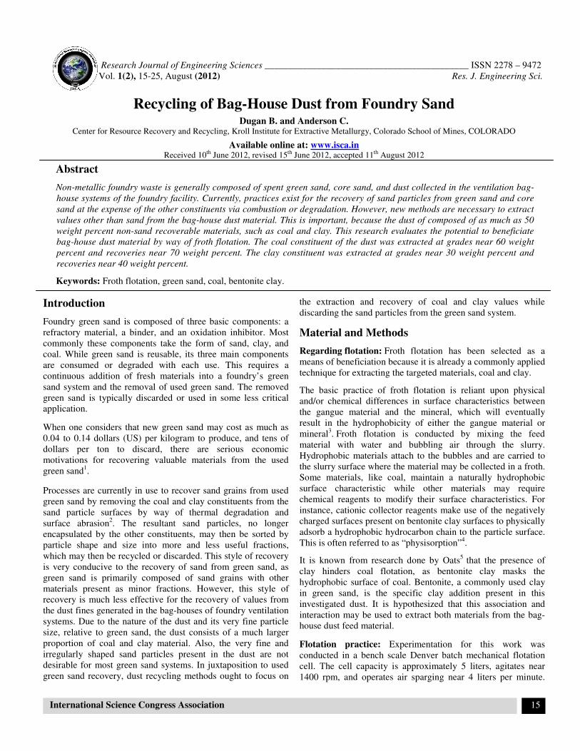
Results from table 1 demonstrate that the bag-house dust is
enriched with coal and bentonite clay, relative to the green sand
it had originated from. This is an expected outcome as the dust
maintains a much finer and broader particle size distribution
relative to the green sand. This is shown in figure 1 and figure 2.
A finer particle size distribution means than the material will
maintain greater surface area per mass and thus contain more
surface encapsulating materials, such as coal and bentonite clay.
In addition, clays simply have a smaller particle size and are
thus more likely to be captured in a ventilation system. As
particle size distribution is very important to the performance of
a green sand mold, figure 1 and figure 2 give evidence
supporting the need to extract valuable materials from the dust
material rather than simply reintroducing sand grains from the
dust back into the green sand system. The smaller, less round
(as shown in figure 3) dust sand grains do not match the desired
particle size distribution of the green sand. Addition of fine
silica from the dust could negatively affect green sand
properties by increasing effective mold density. This would
reduce the ability of escaping gases to be transported through
the green sand mold, require more binder material, and reduce
‘flowability’ of loose sand moving around the foundry’s green
sand system7.
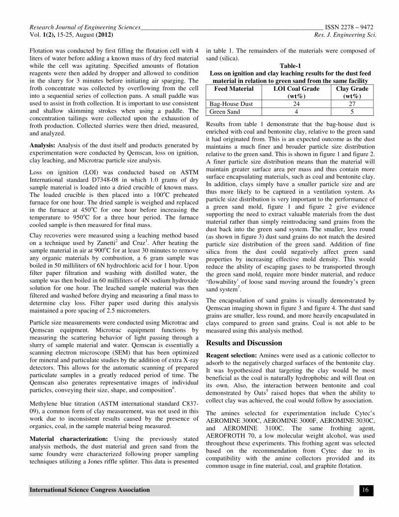
The encapsulation of sand grains is visually demonstrated by
Qemscan imaging shown in figure 3 and figure 4. The dust sand
grains are smaller, less round, and more heavily encapsulated in
clays compared to green sand grains. Coal is not able to be
measured using this analysis method.
Results and Discussion
Reagent selection: Amines were used as a cationic collector to
adsorb to the negatively charged surfaces of the bentonite clay.
It was hypothesized that targeting the clay would be most
beneficial as the coal is naturally hydrophobic and will float on
its own. Also, the interaction between bentonite and coal
demonstrated by Oats5 raised hopes that when the ability to
collect clay was achieved, the coal would follow by association.
The amines selected for experimentation include Cytec’s
AEROMINE 3000C, AEROMINE 3000F, AEROMINE 3030C,
and AEROMINE 3100C. The same frothing agent,
AEROFROTH 70, a low molecular weight alcohol, was used
throughout these experiments. This frothing agent was selected
based on the recommendation from Cytec due to its
compatibility with the amine collectors provided and its
common usage in fine material, coal, and graphite flotation.
Research Journal of Engineering Sciences________________________________________________________ ISSN 2278 – 9472
Vol. 1(2), 15-25, August (2012) Res. J. Engineering Sci.
International Science Congress Association 17
Following some preliminary scoping experiments, one of the
four cationic amine collector reagents provided by Cytec was
selected for continued research. However, all four of the
reagents performed comparably. Table 2 compares the
performance of the Cytec AEROMINE collectors to each other
as well as to the collector absent condition. Each experiment
was conducted with a slurry concentration of 6wt% dust solids,
at natural pH (pH 9), using 320 grams per tonne of collector,
and 600 grams per tonne frother. The reagent quantities used for
these scoping experiments were based on recommendations
from literature that approximately one pound of reagent per ton
of dry material, or about 480 grams per tonne, are used
industrially8.
Table-2
Results for amine selection scoping experiments
Experiment
Coal
Grade
(wt%)
Coal
Recovery
(wt%)
Clay
Grade
(wt%)
Clay
Recovery
(wt%)
no collector 46 35 24 11
3000C 38 52 20 24
3000F 42 48 17 14
3030C 39 51 19 18
3100C 45 45 14 13
Based on results presented in table 2, AEROMINE 3000C was
selected for further research and evaluation of other flotation
variables, because it yielded greatest clay grade and recovery.
Attritioning: All extractive metallurgy and mineral processing
maintains the fundamental basics of liberation and separation.
Attrition scrubbing was selected as the preferred means of
liberation; whereby the act of particle impingement serves to
remove surface encapsulating materials from the particle
surfaces. This was done in accordance with literature from
O’Meara9 which suggests that during silica recovery, foundry
sand should be attrition scrubbed at very high water slurry solids
content, about 70 weight percent solids, and at very high
impeller speeds, about 1750 rpm. However, due to the very high
concentration of clays in the dust material, the slurry solids
content was reduced to near 50 weight percent solids for 5 to 15
minutes.
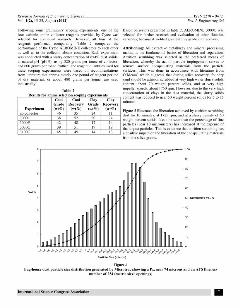
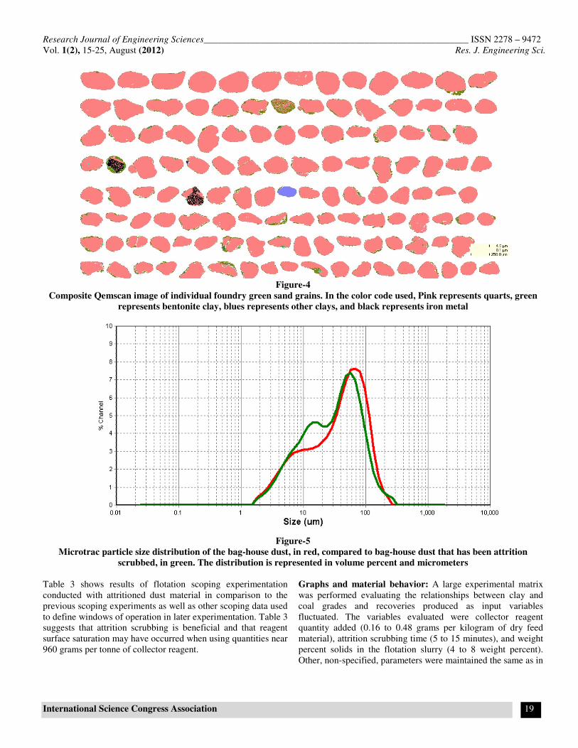
Figure 5 illustrates the liberation achieved by attrition scrubbing
dust for 10 minutes, at 1725 rpm, and at a slurry density of 50
weight percent solids. It can be seen than the percentage of fine
particles (near 10 micrometers) has increased at the expense of
the largest particles. This is evidence that attrition scrubbing has
a positive impact on the liberation of the encapsulating materials
from the silica grains.
Figure-1
Bag-house dust particle size distribution generated by Microtrac showing a P80 near 74 microns and an AFS fineness
number of 234 (metric sieve openings)
0
1
2
3
4
5
6
7
8
1.2
1.4
1.6
1.9
2.3
2.8
3.3
3.9
4.6
5.5
6.5
7.8
9.3
11.0
13.1
15.6
18.5
22.0
26.2
31.1
37.0
44.0
52.3
62.2
74.0
88.0
104.
6
124.4
148.
0
176.
0
209.
3
248.
9
296.0
352.
0
418.
6
Particle Size (micron)
Vol %
0
10
20
30
40
50
60
70
80
90
100
Cumulative Vol. %

Research Journal of Engineering Sciences________________________________________________________ ISSN 2278 – 9472
Vol. 1(2), 15-25, August (2012) Res. J. Engineering Sci.
International Science Congress Association 18
Figure-2
Green sand particle size distribution generated by Microtrac showing a P80 near 352 microns and an AFS fineness number
of 80 (metric sieve openings)
Figure-3
Composite Qemscan image of individual bag-house dust grains, in the color code used, Pink represents quarts, green
represents bentonite clay, blues represents other clays, and black represents iron metal
0
2
4
6
8
10
12
14
16
18
1.2
1.4
1.6
1.9
2.3
2.8
3.3
3.9
4.6
5.5
6.5
7.8
9.311
.013
.115
.618
.522
.026
.231
.137
.044
.052
.362
.274
.088
.0
104.
6
124.
4
148.
0
176.
0
209.
3
248.
9
296.
0
352.
0
418.
6
497.
8
591.
9
703.
9
837.
1
Particle Size (micron)
Vol %
0
10
20
30
40
50
60
70
80
90
100
Cumulative Vol. %
Research Journal of Engineering Sciences________________________________________________________ ISSN 2278 – 9472
Vol. 1(2), 15-25, August (2012) Res. J. Engineering Sci.
International Science Congress Association 19
Figure-4
Composite Qemscan image of individual foundry green sand grains. In the color code used, Pink represents quarts, green
represents bentonite clay, blues represents other clays, and black represents iron metal
Figure-5
Microtrac particle size distribution of the bag-house dust, in red, compared to bag-house dust that has been attrition
scrubbed, in green. The distribution is represented in volume percent and micrometers
Table 3 shows results of flotation scoping experimentation
conducted with attritioned dust material in comparison to the
previous scoping experiments as well as other scoping data used
to define windows of operation in later experimentation. Table 3
suggests that attrition scrubbing is beneficial and that reagent
surface saturation may have occurred when using quantities near
960 grams per tonne of collector reagent.
Graphs and material behavior: A large experimental matrix
was performed evaluating the relationships between clay and
coal grades and recoveries produced as input variables
fluctuated. The variables evaluated were collector reagent
quantity added (0.16 to 0.48 grams per kilogram of dry feed
material), attrition scrubbing time (5 to 15 minutes), and weight
percent solids in the flotation slurry (4 to 8 weight percent).
Other, non-specified, parameters were maintained the same as in
Research Journal of Engineering Sciences________________________________________________________ ISSN 2278 – 9472
Vol. 1(2), 15-25, August (2012) Res. J. Engineering Sci.
International Science Congress Association 20
the scoping experiments. The most significant relationships are
presented in the following figures.
Table-3
AEROMINE 3000C flotation variable scoping data
Experiment
Coal
Grade
(wt%)
Coal
Recovery
(wt%)
Clay
Grade
(wt%)
Clay
Recovery
(wt%)
320 g/t 3000C 38 52 20 24
960 g/t 3000C 43 47 18 15
320g/t 3000C,
Attritioned 45 51 24 16
320 g/t 3000C,
Attritioned, 12
wt% solids 32 54 24 39
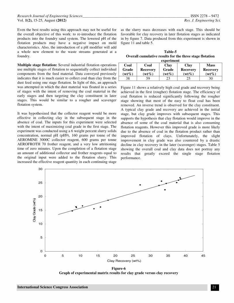
Overall, clay grades and recoveries generated by
experimentation produced disappointing results. Feed grade
remained the upper limit of the flotation capabilities. Figure 6
illustrates the clay grade and recovery results and shows a direct
relationship with one another. This suggests that they are both
following mass pull. As more material is recovered more clay is
being recovered, but without actually beneficiating the material.
This indicates that either the feed material is not liberated before
flotation and/or selectivity is not being achieved by the reagent
and flotation parameters during flotation. This statement is
further supported by figure 7 which shows a positive
relationship between grade and the increasing of both input
variables. Figure 7 also shows a stronger relationship between
grade and slurry solids concentration than other input variables.
A strong relationship was not observed between attrition time
variance and clay beneficiation.
The coal grades and recoveries generated by the same set of
experiments produced results which illustrate an inverse
relationship between grade and recovery. This is a classic trade
off scenario in which enrichment is obtained at the expense of
recovery. Figure 8 depicts this relationship. However, unlike
clay this shows that the coal can be beneficiated well above feed
grade while maintaining moderate recovery.
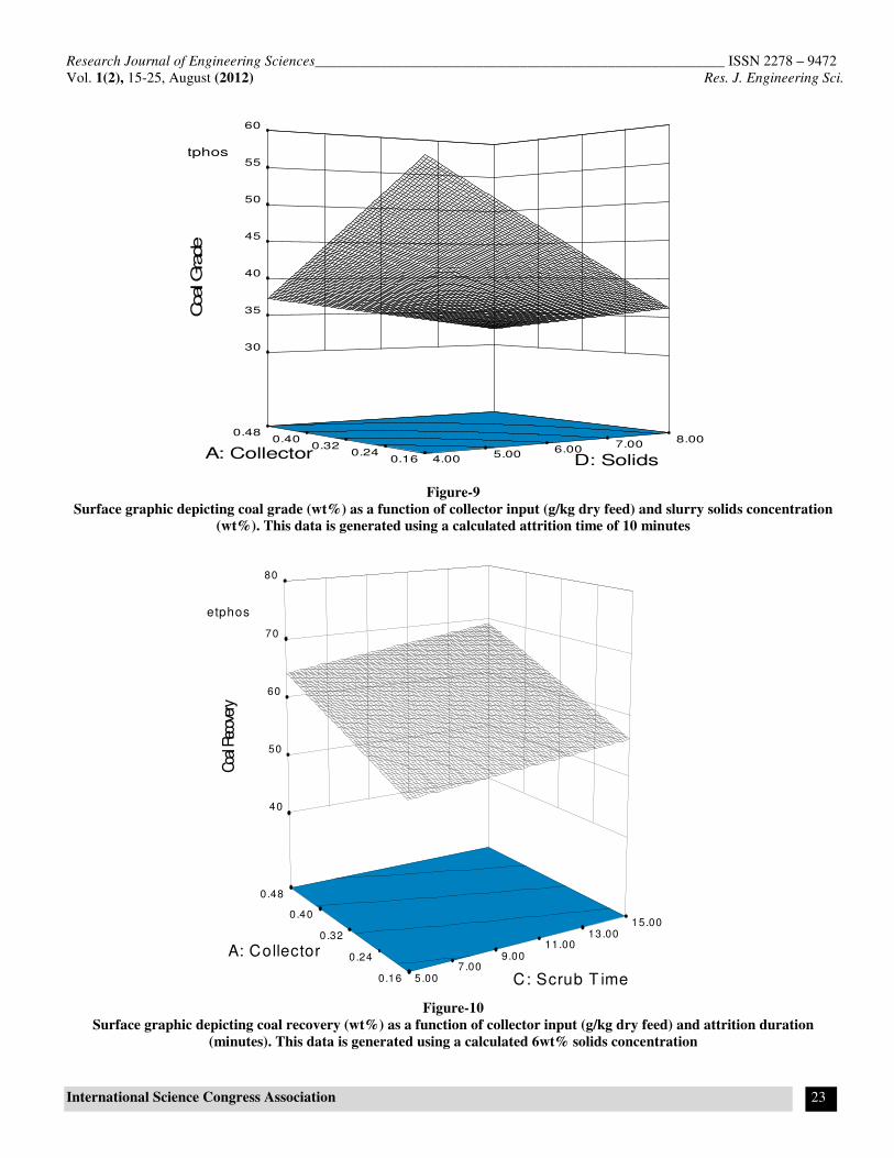
Figure 9 and figure 10 are surfaces used to reveal the optimum
conditions at which to conduct the separation. Based on these
surfaces it can be deduced that one way to obtain the maximum
coal grade product is to collect the least amount of material.
Figure 9 shows the maximum coal grade being obtained with
the minimum amount of collector and solids addition.
Minimizing attrition duration also improves grade as seen in
figure 10. Due to its inverse relationship, grade is likewise
minimized by maximizing recovery via high collector addition,
high solids concentration, and long attrition duration.
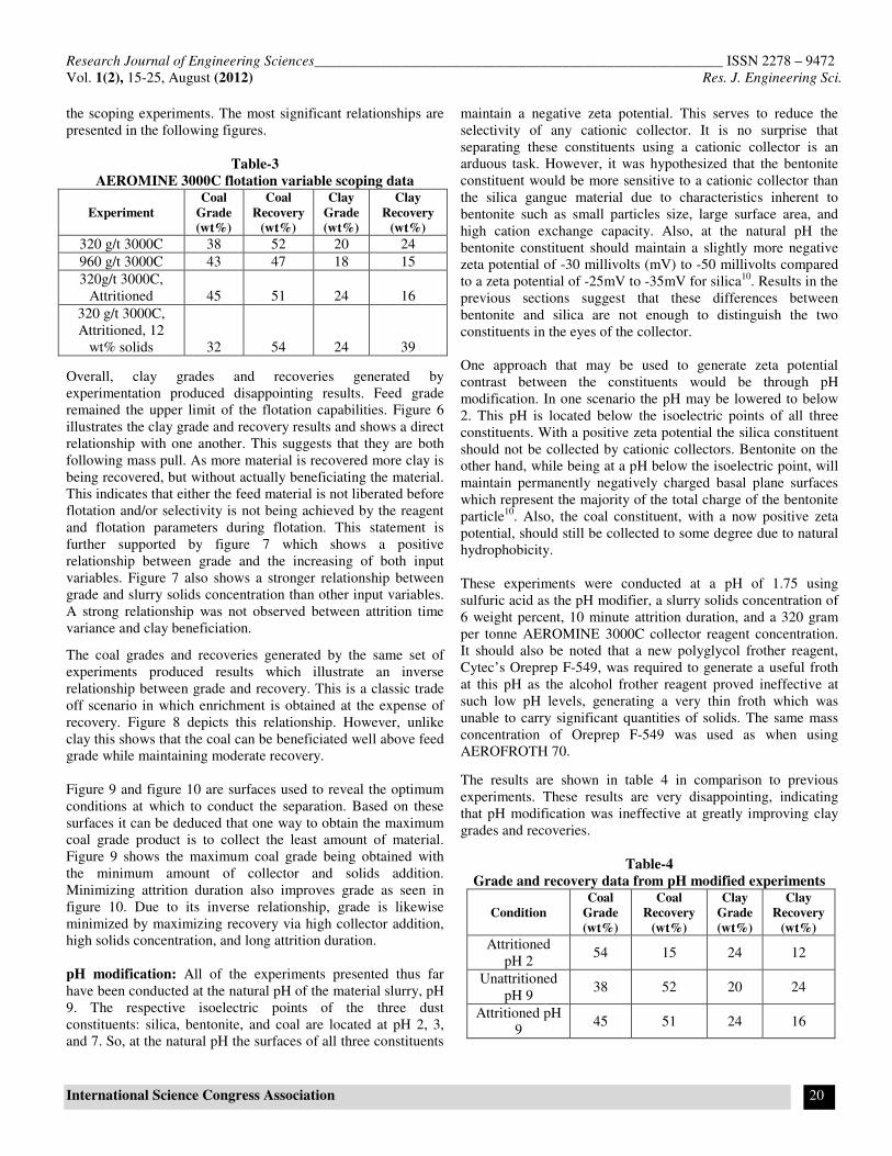
pH modification: All of the experiments presented thus far
have been conducted at the natural pH of the material slurry, pH
9. The respective isoelectric points of the three dust
constituents: silica, bentonite, and coal are located at pH 2, 3,
and 7. So, at the natural pH the surfaces of all three constituents
maintain a negative zeta potential. This serves to reduce the
selectivity of any cationic collector. It is no surprise that
separating these constituents using a cationic collector is an
arduous task. However, it was hypothesized that the bentonite
constituent would be more sensitive to a cationic collector than
the silica gangue material due to characteristics inherent to
bentonite such as small particles size, large surface area, and
high cation exchange capacity. Also, at the natural pH the
bentonite constituent should maintain a slightly more negative
zeta potential of -30 millivolts (mV) to -50 millivolts compared
to a zeta potential of -25mV to -35mV for silica10
. Results in the
previous sections suggest that these differences between
bentonite and silica are not enough to distinguish the two
constituents in the eyes of the collector.
One approach that may be used to generate zeta potential
contrast between the constituents would be through pH
modification. In one scenario the pH may be lowered to below
2. This pH is located below the isoelectric points of all three
constituents. With a positive zeta potential the silica constituent
should not be collected by cationic collectors. Bentonite on the
other hand, while being at a pH below the isoelectric point, will
maintain permanently negatively charged basal plane surfaces
which represent the majority of the total charge of the bentonite
particle10
. Also, the coal constituent, with a now positive zeta
potential, should still be collected to some degree due to natural
hydrophobicity.
These experiments were conducted at a pH of 1.75 using
sulfuric acid as the pH modifier, a slurry solids concentration of
6 weight percent, 10 minute attrition duration, and a 320 gram
per tonne AEROMINE 3000C collector reagent concentration.
It should also be noted that a new polyglycol frother reagent,
Cytec’s Oreprep F-549, was required to generate a useful froth
at this pH as the alcohol frother reagent proved ineffective at
such low pH levels, generating a very thin froth which was
unable to carry significant quantities of solids. The same mass
concentration of Oreprep F-549 was used as when using
AEROFROTH 70.
The results are shown in table 4 in comparison to previous
experiments. These results are very disappointing, indicating
that pH modification was ineffective at greatly improving clay
grades and recoveries.
Table-4
Grade and recovery data from pH modified experiments
Condition
Coal
Grade
(wt%)
Coal
Recovery
(wt%)
Clay
Grade
(wt%)
Clay
Recovery
(wt%)
Attritioned
pH 2 54 15 24 12
Unattritioned
pH 9 38 52 20 24
Attritioned pH
9 45 51 24 16
Research Journal of Engineering Sciences________________________________________________________ ISSN 2278 – 9472
Vol. 1(2), 15-25, August (2012) Res. J. Engineering Sci.
International Science Congress Association 21
Even the best results using this approach may not be useful for
the overall objective of this work: to re-introduce the flotation
products into the foundry sand system. The lowered pH of the
flotation products may have a negative impact on mold
characteristics. Also, the introduction of a pH modifier will add
a whole new element to the waste streams generated at a
foundry.
Multiple stage flotation: Several industrial flotation operations
use multiple stages of flotation to sequentially collect individual
components from the feed material. Data conveyed previously
indicates that it is much easier to collect coal than clay from the
dust feed using one stage flotation. In light of this, an approach
was attempted in which the dust material was floated in a series
of stages with the intent of removing the coal material in the
early stages and then targeting the clay constituent in later
stages. This would be similar to a rougher and scavenger
flotation system.
It was hypothesized that the collector reagent would be more
effective in collecting clay in the subsequent stage in the
absence of coal. The inputs for this experiment were selected
with the intent of maximizing coal grade in the first stage. The
experiment was conducted using a 6 weight percent slurry solids
concentration, normal pH (pH9), 160 grams per tonne of the
AEROMINE 3000C collector reagent, 600 grams per tonne
AEROFROTH 70 frother reagent, and a very low attritioning
time of zero minutes. Upon the completion of a flotation stage
an amount of additional collector and frother reagents equal to
the original input were added to the flotation slurry. This
increased the effective reagent quantity in each continuing stage
as the slurry mass decreases with each stage. This should be
favorable for clay recovery in later flotation stages as indicated
in by figure 7. Data produced from this experiment is shown in
figure 11 and table 5.
Table-5
Overall cumulative results for the three stage flotation
experiment
Coal
Grade
(wt%)
Coal
Recovery
(wt%)
Clay
Grade
(wt%)
Clay
Recovery
(wt%)
Mass
Recovery
(wt%)
38 59 23 25 30
Figure 11 shows a relatively high coal grade and recovery being
achieved in the first (rougher) flotation stage. The efficiency of
coal flotation is reduced significantly following the rougher
stage showing that most of the easy to float coal has been
removed. An inverse trend is observed for the clay constituent.
A typical clay grade and recovery are achieved in the initial
stage, but clay grade improves with subsequent stages. This
supports the hypothesis that clay flotation would improve in the
absence of some of the coal material that is also consuming
flotation reagents. However this improved grade is more likely
due to the absence of coal in the flotation product rather than
improved flotation of clays. Unfortunately, the slight
improvement in clay grade was also countered by a drastic
decline in clay recovery in the later (scavenger) stages. Table 5
showing the overall coal and clay data does not portray any
results that greatly exceed the single stage flotation
performance.
Figure-6
Graph of experimental matrix results for clay grade versus clay recovery
0
5
10
15
20
25
30
0 5 10 15 20 25 30 35 40 45
Clay Recovery (wt%)
Cla
y G
rade (w
t%)

Research Journal of Engineering Sciences________________________________________________________ ISSN 2278 – 9472
Vol. 1(2), 15-25, August (2012) Res. J. Engineering Sci.
International Science Congress Association 22
Figure-7
Surface graphic depicting clay grade (wt%) as a function of collector input (g/kg dry feed) and slurry solids concentration
(wt%). This data is generated using a calculated attrition time of 10 minutes
Figure-8
Graph of experimental matrix results for coal grade versus coal recovery
B: Dispersant = NaHexmetphos
0.16
0 .24
0.32
0 .40
0 .48
4.00
5 .00
6 .00
7 .00
8 .00
14
16
18
20
22
24
26
28
Clay Gra
de
D: Solids A: Collector
0
10
20
30
40
50
60
70
35 40 45 50 55 60 65 70 75 80
Coal Recovery (wt%)
Coal Gra
de (wt%
)
Research Journal of Engineering Sciences________________________________________________________ ISSN 2278 – 9472
Vol. 1(2), 15-25, August (2012) Res. J. Engineering Sci.
International Science Congress Association 23
Figure-9
Surface graphic depicting coal grade (wt%) as a function of collector input (g/kg dry feed) and slurry solids concentration
(wt%). This data is generated using a calculated attrition time of 10 minutes
Figure-10
Surface graphic depicting coal recovery (wt%) as a function of collector input (g/kg dry feed) and attrition duration
(minutes). This data is generated using a calculated 6wt% solids concentration
B: Dispersant = NaHexmetphos
0.16 0.24
0.32 0.40
0.48
4.00 5.00
6.00 7.00
8.00
30
35
40
45
50
55
60
Coal Gra
de
D: Solids A: Collector
B: Dispersant = NaHexmetphos
0.16
0.24
0 .32
0.40
0.48
5 .00 7 .00
9.00 11.00
13 .00 15.00
40
50
60
70
80
Coa
l Rec
over
y
C: Scrub T ime
A: Collector

Research Journal of Engineering Sciences________________________________________________________ ISSN 2278 – 9472
Vol. 1(2), 15-25, August (2012) Res. J. Engineering Sci.
International Science Congress Association 24
Figure-11
Multiple stage flotation grade and recovery results by stage
Conclusion
The overall goal of this project was to recycle foundry dust back
into the foundry green sand inputs. It was hoped that high
selectivity between constituents could be achieved by using a
collector reagent to target specific constituents within the
material system. However, the very fine nature of the material
provided a challenge for flotation techniques. It is for this
reason that industrial coal flotation operations typically de-slime
their feed material before conducting flotation. Unfortunately, in
this case de-sliming was not an option as the slimes were
composed of the desired materials.
The experiments conducted in this research show that is it very
difficult to beneficiate the clay constituent via froth flotation.
The hydrophilic nature and small particle size of the clay
combined with its similarity to the silica gangue material greatly
impair the selectivity of the flotation regime. It was
hypothesized that the clay’s constantly negative surface
potential and high cation exchange capacity would make it a
suitable candidate for cationic physical adsorption flotation, but
most experimental techniques did not achieve clay grades in
excess of the feed grade. It is hypothesized that the reason for
clay’s poor flotability is due to the lack of selectivity of the
collector reagent, inherent slime characteristics, and the inability
to fully liberate the material constituents.
Low slurry density and collector addition proved to improve
clay grades by recovering only readily floating materials, but as
mass recovery increased with increased collector and slurry
density, selectivity was lost. Even multiple stage flotation did
not improve the relationship between grade and recovery. The
barrier here, as with industrial coal flotation from primary
sources, appears to be the fine silica ‘slime’ material which
becomes entrained in the flotation froth and contaminates the
final product
Beneficiation of the dust’s coal constituent proved to be
relatively successful. Grades above 60wt% coal have been
achieved along with recoveries above 70wt% coal.
Unfortunately these results never occurred together in the same
experiment.
The primary outcome from this research is that the clay and coal
constituents can be collected and independently separated from
one another. However, an efficient method must still be
identified which is suitable for this very fine particulate
material.
0
5
10
15
20
25
30
35
40
45
0 1 2 3 4
Stage
(wt%
)
Coal Grade
Clay Grade
Coal Recovery
Clay Recovery

Research Journal of Engineering Sciences________________________________________________________ ISSN 2278 – 9472
Vol. 1(2), 15-25, August (2012) Res. J. Engineering Sci.
International Science Congress Association 25
References
1. Cruz Nestor et al., Green Sand Reclamation Using a
Fluidized Bed with an Attrition Nozzle, Resources,
Conservation and Recycling, 54 (2009)
2. Zanetti M.C. and Fiore S., Foundry Processes: the
Recovery of Green Moulding Sands for Core Operations,
Resources, Conservation, and Recycling 38 (2002)
3. Wills B.A., Mineral Processing Technology: 5th
Edition, An
Introduction to the Practical Aspects of Ore Treatment and
Mineral Recovery (1992)
4. Fuerstenau D.W. and Pradip, Zeta Potentials in the
Flotation of Oxide and Silicate Minerals, Advances in
Colloid and Interface Science (2005)
5. Oats W.J. et al., Effect of Mechanical and Chemical Clay
Removals by Hydrocyclone and Dispersants on Coal
Flotation, Minerals Engineering (2009)
6. Goodall W.R., The Use of QEMSCAN and Diagnostic
Leaching in the Characterization of Visible Gold in
Complex Ores, Minerals Engineering, 18 (2005)
7. Piwonka T.S., Aggregate Molding Materials. ASM
Handbook Volume 15: Casting (1992)
8. Holuszko M.E., Advanced Coal Processing Short Course,
University of British Columbia (2009)
9. O’Meara P. et al., Bonded Sand Molds. ASM Handbook
Volume 15: Casting (1992)
10. Baik M.H. and Lee S.Y., Colloidal Stability of Bentonite
clay Considering Surface Charge Properties as a Function
of pH and Ionic Strength, Journal of Industrial and
Engineering Chemistry (2010)
11. Williams S.R. et al., Bench and Pilot Plant Programs for
Flotation Circuit Design, Mineral Processing Plant Design,
Practice, and Control, Ed. Mular, A.L. Halbe, D.N. Barratt,
D.J. (2002)