Embed Size (px)
Citation preview

© Strojniški vestnik 47(200138,462-467 ISSN 003S-24B0 UDK 536.2Izvirni znanstveni članek (1,013
©Journal of Mechanical Engineering 47C200138,462-467ISSN 003S-2480
UDC 536.2 Original scientific paper C1 .013
RECUPERATED GAS TURBINE INTEGRATED WITH THE PFBC COMBINED CYCLE POWER PLANT
R. ChodkiewiczInstitute o f Turbomachinery
Technical University o f Lodz 219/223 Wolczanska
Lodz, 93-005, Poland rchod@ ck-sg.p.lodz.pl
B. Donevski, ASME Member Faculty o f Technical Sciencies University “St Clement Ohridski” Bitola, 7000, p.o. box 99 Macedoniabozin.donevski@ uklo.edu.mk
J . K rysinskiInstitute o f Turbomachinery
Technical University o f Lodz 219/223 W olczanska
Lodz, 93-005 Poland
J. KrztonEx-Head o f Design
Department Foster Wheeler Energy Fakop
Poland
J. PorochnickiInstitute o f Turbomachinery Technical University o f Lodz 219/223 W olczanska Lodz, 93-005 Poland
ABSTRACTFluidized bed combustion (FBC) is well suited for firing
various sorts o f hard coal and lignite, and co-firing coal with other fuels (wastes, biomass), and it is characterized by low air pollution. Conventional pressurized fluidized bed combustion (PFBC) power plants operate at the nominal combustion temperature 870°C for optimal sulfur capture. Since this temperature is well below the turbine inlet temperature o f the current gas turbines, a topping gas turbine cycle has been proposed that can enhance the cycle efficiency of the conventional PFBC plants. In the topping cycle a recuperated gas turbine fuelled with natural gas utilizes the coal combustion heat to preheat the compressed air before the gas turbine combustor. An influence of such an “external heat recuperation” on efficiency, power and total fuel costs for various proportions of used coal and natural gas in the proposed advanced PFBC plant has been analyzed.
INTRODUCTIONCoal fuels, the most widespread kind of fossil fuels in the
world, will still remain the safest primary energy source with stable prices in the next century. Predictions show that about 50% of the generated power in the new installed power stations will come from coal fuels at the average power rate of about 70 GW through the next 10 to 20 years. Realization o f future power plant projects will be based on the possibility of assuring low investment and operating costs, short construction times, and the highest level o f reliability. More ecologically advantageous solutions will be preferred as well. The operating costs decrease can be attainable only by increasing the energy conversion efficiency due to the application o f high parameters of live steam (supercritical and ultra supercritical parameters - Bell, et al. 1999, Retzlaw, et al., 1998, Simon, 1997, Stapper, 1997).
Research and implementation of new technologies based on coal, which offer higher efficiencies than those achieved in
modem power plants, with lower ecological hazards, can also contribute to the energy market stability. Special attention should be paid to the fluidized bed combustion technology for coal fuels. Fluidized bed combustion (FBC) is well suited for firing various sorts of hard coal and lignite, and co-firing coal with other fuels (wastes, biomass), and is characterized by low air pollution. Conventional FBC power plants based on the Rankin steam turbine cycle have relatively low efficiency. The efficiency can be slightly improved in pressurized fluidized bed combustion (PFBC) combined cycle power plants that incorporate the more efficient Brayton gas turbine cycle (Evans & Anastasiou, 1985), (Kraemer, 1988), (Weirich & Pillai). The pressurized bed combustor operates at the nominal temperature 870°C for optimal sulfur capture.
In a typical first-generation PFBC power plant, the gas turbine / steam turbine duty split is about 0.2/0.8. The further development o f the above mentioned technology, integrated with other processes is announced (so-called Hybrid-PFBCC process). It should allow one to get efficiency in the range 50+53%.
One of the efficiency enhancement methods in the power plants with PFBC technology (without a turbine inlet temperature increase) is a solution with a dual Brayton cycle gas turbine - DBC-GT (Yan & Lidski, 1998). The power plant in that conception consists of two coupled gas turbine cycles - one working in an open cycle and another working in a close cycle. The gas turbine in the open cycle (with heat recuperation and intersection cooling) is supplied by fluidized boiler exhaust gases. Simultaneously, this boiler is a working medium heater for the second cycle (close cycle), in which about 75% of the whole system electric power is generated. Helium is the working medium for this cycle. The DBC-GT power plant can achieve thermal net efficiency equal to 44.5% only, which is similar to values obtained in the conventional combined gas- steam PFBC power plants. It results from a great amount of heat
IsrüWByiMGScsiil
(in the exhaust gases and in the cooling medium) transferred directly to the environment. The benefits which one can suspect in that solution can be seen in the significant power concentration, which results from high medium density in the main helium cycle (max. pressure value of about 67 bar), and in the significant pressure inside the fluidized bed of the boiler. Thanks to that, the machines and devices in the energy system have a compact structure, and high temperature outlet heat allows one to use a dry fan cooler (air), which means that the installation can be located in the places with limited water resources.
The other method of increasing the efficiency in the power plant combined with PFBC technology is a connection with the partial coal gasification (pyrolysis - Domeracki, et al., 1997, Krammer & Pillai). Low caloric gas, obtained in that way, could be used in the topping combustor, in which this gas is burnt in the stream of the fluidized bed boiler exhaust gases. Coal would be combusted in the boiler, together with the pyrolysis discharge products. This process should be realized with the high air excess, and should allow one to get the turbine inlet temperature of about 1100*1150°C, but under condition that the boiler exhaust gases were cleaned better (ceramic candle filters) than in the conventional PFBC power plants with the operating temperature lower than 900°C.
The other way to increase the flue gas temperature to some desired level at the inlet gas turbine is to introduce a topping combustor fired with natural gas. Taking into consideration the fact that natural gas is a premium fuel, its usage must be rational from the economical and ecological point of view. The combination of natural gas fuelled processes with processes based on coal should be recognized with special attention in countries with limited natural gas resources (e.g. Poland and Macedonia).
The main objective of the proposed model of a PFBC power plant is to study some different strategies to improve the efficiency of the classical power plants under operation. In this paper a developed model o f the efficiency improvement strategies and its results are described. The ecological reasons are considered in this study as well.
ADVANCED PFBC POWER PLANT DESCRIPTIONIn the advanced PFBC power plant, as proposed, the
recuperated gas turbine fuelled with natural gas is superimposed on the so-called non-topping PFBC system (first-generation PFBC system). The heat recuperation consists in the compressed air preheating upstream the gas turbine combustor by means of the external heat source. This heat source is the fluidized bed or/and high temperature flue gas from the coal boiler. Such external heat recuperation in gas turbines can also be used in many industrial processes with great amounts of process or waste heat production (e.g. chemical, petrochemical industry, ...). Such applications have been widely analyzed in earlier author works (e.g. Chodkiewicz, et al., 2000).
The application of natural gas in the recuperated gas turbine coupled with the PFBC plant allows one to increase the topping temperature o f the energy system in the range attainable in the current gas turbine working in the combined gas-steam cycles. On the other hand, the external heat recuperation causes a significant reduction of the amount o f the premium fuel needed for the gas turbine combustor due to the compressed air preheating with a less expensive fuel (e.g. coal). The
compressor cooling can also be necessary for better adjustment of the compressed air temperature to the external heat source temperature.
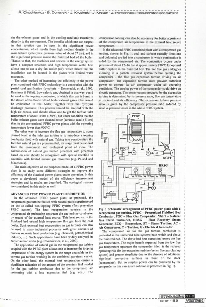
In the advanced PFBC combined plant with a recuperated gas turbine, shown in Fig. 1, coal and sorbent (usually limestone and dolomite) are fed into a combustor in which combustion is aided by the compressed air. The combustion occurs under pressure of about 12* 16 bar at approximately 870°C for optimal sulfur capture in the fluidized bed. The hot flue gas undergoes cleaning in a particle removal system before entering the compander - the flue gas expansion turbine driving an air compressor. The expansion turbine must provide sufficient power to operate its air compressor under all operating conditions. The surplus power of the compander could drive an electric generator. The power output produced by the expansion turbine is determined by its pressure ratio, flue gas temperature at its inlet and its efficiency. The expansion turbine pressure ratio is given by the compressor pressure ratio reduced by relative pressure losses in the whole PFBC system.
Fig. 1 Schematic arrangement of PFBC power plant with a recuperated gas turbine. PFBC - Pressurized Fluidized Bed Combustor, FGC - Flue Gas Compander, NGFT - Natural Gas Fired Turbo-Set, HRSG - Heat Recovery Steam Generator, ECO - Economizer, ST - Steam Turbine, AC - Air Compressor, T - Turbine, G - Electrical Generator.
The compressed air for the gas turbine combustor is preheated in the immersed tube systems both within and above the fluidized bed. The above bed heat extraction lowers the flue gas temperature. The major benefit expected from the low flue gas temperature upstream the compander inlet is the reduced operating risk for the expansion turbine (better flue gas cleanup system) and greater simplicity due to the absence of additional high-level convective surfaces in front o f the stack (economizer). But no surplus power can be produced by the compander in this case (such solution is presented in Fig. 1).
The steam is generated in a heat recovery steam generator (HRSG) downstream the gas turbine. This steam drives a steam turbine, completes the combine cycle with the natural gas fired turbo-set (NGFT) and the flue gas compander (FGC). The economizer behind the flue gas expansion turbine and the feed water preheating system combined with the condensate fed the intercooler of the compressors supplementing the new advanced PFBC energy system.
ENERGY SYSTEM ANALYSISIn the analysis some cases of the advanced PFBC system are
compared with the well known P200 power plant built by ABB (e.g. Anderson 1999, Krammer, 1998). The performance data for the conventional PFBC energy system calculations and for the advanced PFBC power plant calculations are collected in Table 1+3.
Table 1 Results of the Conventional PFBC System Calculations (checking calculations of the P-200 power plant)___________________________________________
Thermal input (LHV) MWt 1 9 6 .0Compander output, gross MWe 1 6 .0Steam turbine output, gross MWe 6 4 .3Gross electrical output MWe 8 0 .0Auxiliary power MWe 3 .5Net electrical output MWe 7 6 .5Net plant efficiency (LHV) % 3 9 .2Rei. coal costs (Poland) $/MWh 1 5 .7Rei. coal costs (Macedonia) $/MWh 2 2 .5C 02 relative emission kq/MWh 4 5 6 .6NOx relative emission kg/MWh 0 .4 3 5S02 relative emission kg/MWh 2 .2 4 2
Table 2 Compander efficiencies and pressure lossesPFBC compressor efficiency [%1 90.0PFBC turbine efficiency [%1 86.0Total pressure losses in the PFBC boiler [%]_ 15.0
Table 3 Gas turbine pressure losses and efficienciesInlet filter f%l 1 .0Compressor inlet [%1 0 .5Compressor diffuser [%1 2 .0External recuperator r%i 3 .5Combustor r%i 2 .5Turbine inlet \%] 1 .0Turbine diffuser \%] 3 .0Waste heat boiler \%] 2 .5Stack f%i 1 .0Gas turbine compressor efficiency r%i 8 9 .0Gas turbine basic efficiency _[% L 9 0 .0
The following assumptions have been made in the computational process:
1. Pressure losses, efficiencies for the conventional PFBC power plant are presented in Table 2 and for the externally recuperated gas turbine in Table 3.
2. The coal chemical energy flow is constant in each considered variant and equals to 196 MWt (conventional P-200 power plant operating data).
3. The economizer located at the compander outlet has constant output at constant flue gas parameters (inlet temperature 830°C and inlet pressure 10.2 bar).
4. The PFBC stack conditions: 140°C/1.08 bar.5. The steam turbine works without steam reheating, and is
fed by the steam from the three-pressure heat recovery steam generator (downstream the gas turbine). Steam parameters are equal to - inlet temperature 535°C, inlet pressure 110 bar (conventional P-200 power plant operating data).
6. The steam turbine efficiency and the feed water preheating system do not change in all considered variants.
7. The heat from the intersection compressor cooling and from the PFBC economizer (downstream compander) is used in the steam cycle.
8. The polytropic efficiency is a function of the turbine inlet temperature, stage numbers and varies along the flow path. The cooling air mass flow is a function of the turbine inlet temperature (Rufli 1990) - initial turbine efficiency (without cooling) is constant and equals to 90 %.
RESULTS OF CALCULATIONS AND CONCLUSIONSThe main results of computations made for the above
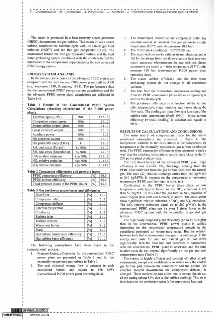
mentioned assumptions are presented in Table 4. The independent variable in the calculations is the compressed air temperature at the externally recuperated gas turbine combustor inlet. The PFBC compander efficiencies were assumed in such a way that the checking calculations results were close to the P- 200 power plant producer data.
The first direct benefit of the advanced PFBC plant high efficiency is low specific C 02 discharge, coming from the PFBC coal boiler and from the gas turbine fired with the natural gas. The total C 02 relative discharge varies from 160 kg/MWh to 240 kg/MWh. It depends on the compressed air reheating temperature (PFBC coal fuel input is constant).
Combustion in the PFBC boiler takes place at low temperature with typical limits for the NOx emissions lower than 50 mg/MJ. To this value the gas turbine NOx emission of about 25ppm (low emission burners) is added. The calculations show significant relative reduction of NOx and S02 emissions. The NOx relative emissions equal up to 500 g/MWh in the conventional PFBC plant can be even 3 times lower in the advanced PFBC system with the externally recuperated gas turbine.
The high newly proposed plant efficiency (up to 10 % higher than in the conventional PFBC power plant) is weakly dependent on the recuperated temperature growth in the considered preheated air temperature range. But the relation between both fuel consumptions changes in a wide range. If the energy unit costs for coal and natural gas do not differ significantly, then the total fuel cost decreases in comparison with the conventional PFBC plant is observed, and the total relative costs do not depend significantly on the gas and coal consumption ratio (Table 4).
The system is highly efficient and consists of rather simple components, except one modification in which only the central gas turbine part between the compressor and the turbine (air chamber located downstream the compressor diffuser) is changed. Those modernizations allow one to extract the air out of the casing (about 80% due to the turbine cooling). This air is introduced to the combustor again (after appropriate heating).
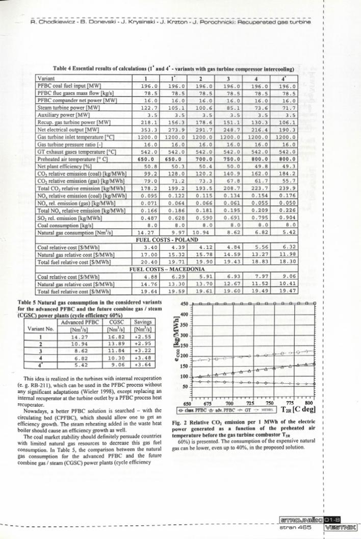
Table 4 Essential results of calculations (1* and 4* - variants with gas turbine compressor intercooling)Variant 1 r 2 3 4 4‘PFBC coal fuel input fMWl 1 9 6 .0 1 9 6 .0 1 9 6 .0 1 9 6 .0 1 9 6 .0 1 9 6 .0PFBC flue gases mass flow fkg/sl 7 8 .5 7 8 .5 7 8 .5 7 8 .5 7 8 .5 7 8 .5PFBC compander net power (MW) 1 6 .0 1 6 .0 1 6 .0 1 6 .0 1 6 .0 1 6 .0Steam turbine power [MW) 1 2 2 .7 1 0 5 .1 1 0 0 .6 8 5 .1 7 3 .6 7 1 .7Auxiliary power (MW] 3 .5 3 .5 3 .5 3 .5 3 .5 3 .5Recup. gas turbine power (MW) 2 1 8 .1 1 5 6 .3 1 7 8 .6 1 5 1 .1 1 3 0 .3 1 0 6 .1Net electrical output fMWl 3 5 3 .3 2 7 3 .9 2 9 1 .7 2 4 8 .7 2 1 6 .4 1 9 0 .3Gas turbine inlet temperature r°C| 1 2 0 0 .0 1 2 0 0 .0 1 2 0 0 .0 1 2 0 0 .0 1 2 0 0 .0 1 2 0 0 .0Gas turbine pressure ratio f-1 1 6 .0 1 6 .0 1 6 .0 1 6 .0 1 6 .0 1 6 .0GT exhaust gases temperature r°C| 5 4 2 .0 5 4 2 .0 5 4 2 .0 5 4 2 .0 5 4 2 .0 5 4 2 .0Preheated air temperature f° Cl 650.0 650.0 700. 0 750. 0 800.0 800.0Net plant efficiency [%] 5 0 .8 5 0 .3 5 0 .4 5 0 .0 4 9 .8 4 9 .3CO, relative emission (coal) fkg/MWhl 9 9 .2 1 2 8 .0 1 2 0 .2 1 4 0 .9 1 6 2 .0 1 8 4 .2CO, relative emission (gas) [kg/MWh] 7 9 .0 7 1 .2 7 3 .3 6 7 .8 6 1 .7 5 5 .7Total CO, relative emission fkg/MWh] 1 7 8 .2 1 9 9 .2 1 9 3 .5 2 0 8 .7 2 2 3 .7 2 3 9 .9NOx relative emission (coal) fkg/MWhl 0 .0 9 5 0 .122 0 .1 1 5 0 .1 3 4 0 .1 5 4 0 .1 7 6NO, rei. emission (gas) (kg/MWh] 0 .0 7 1 0 .0 6 4 0 .0 6 6 0 .0 6 1 0 .0 5 5 0 .0 5 0Total NOx relative emission fkg/MWhl 0 .1 6 6 0 .1 8 6 0 .1 8 1 0 .1 9 5 0 .2 0 9 0 .2 2 6SO, rei. emission fkg/MWh] 0 .4 8 7 0 .6 2 8 0 .5 9 0 0 .6 9 1 0 .7 9 5 0 .9 0 4Coal consumption fkg/sl 8 .0 8 .0 8 .0 8 .0 8 .0 8 .0Natural gas consumption [Nm3/s] 1 4 .2 7 9 .9 7 1 0 .9 4 8 .6 2 6 .8 2 5 .4 2
FUEL COSTS - POLANDCoal relative cost f$/MWhl 3 .4 0 4 .3 9 4 .1 2 4 .8 4 5 .5 6 6 .3 2Natural gas relative cost f$/MWhl 1 7 .0 0 1 5 .3 2 1 5 .7 8 1 4 .5 9 1 3 .2 7 1 1 .9 8Total fuel relative cost [$/MWh] 2 0 .4 0 1 9 .7 1 1 9 .9 0 1 9 .4 3 1 8 .8 3 1 8 .3 0
FUEL COSTS - MACEDONIACoal relative cost f$/MWhl 4 .8 8 6 .2 9 5 .9 1 6 .9 3 7 .9 7 9 .0 6Natural gas relative cost f$/MWh] 1 4 .7 6 1 3 .3 0 1 3 .7 0 1 2 .6 7 1 1 .5 2 1 0 .4 1Total fuel relative cost f$/MWh] 1 9 .6 4 1 9 .5 9 1 9 .6 1 1 9 .6 0 1 9 .4 9 1 9 .4 7
Table 5 Natural gas consumption in the considered variants for the advanced PFBC and the future combine gas / steam
This idea is realized in the turbines with internal recuperation (e. g. RB-211), which can be used in the PFBC process without any significant adaptations (Wieler 1998), except replacing an internal recuperator at the turbine outlet by a PFBC process heat recuperator.
Nowadays, a better PFBC solution is searched - with the circulating bed (CPFBC), which should allow one to get an efficiency growth. The steam reheating added in the waste heat boiler should cause an efficiency growth as well.
The coal market stability should definitely persuade countries with limited natural gas resources to decrease this gas fuel consumption. In Table 5, the comparison between the natural gas consumption for the advanced PFBC and the future combine gas / steam (CGSC) power plants (cycle efficiency
IgrinaiäiaflRfligcaiscran 465
(CGSC) power plants (cycle efficiency 60%)
Variant No.Advanced PFBC CGSC Savings
fNmVsl TNmVsl fNmVsl1 1 4 .2 7 1 6 .8 2 + 2 .552 1 0 .9 4 1 3 .8 9 + 2 .953 8 .6 2 1 1 .8 4 + 3 .224 6 .8 2 1 0 .3 0 + 3 .4 84* 5 .4 2 9 .0 6 +3 .64
450
4on :
Q--&- □ Q- □ .Q— .£
? 1^0 "
& 50i»— e - ^ — c :
« <
--- T— . (+ -«L/---^--- -
6501 1 l” l J
675 700 725 750 775 800I-6 -ciati. PFBC ■&- adv. PFBC -+- GT - - «m u. ] T 2r [ C d e g ]
Fig. 2 Relative C 02 emission per 1 MWh of the electric power generated as a function of the preheated air temperature before the gas turbine combustor T2R
60%) is presented. The consumption of the expensive natural gas can be lower, even up to 40%, in the proposed solution.
01 -8

1------B ------B - 1------B ------ B - - B ------B ------ )------ B ------0 - - B ------B ------1
. . — v
i----- ?-------►+- - e - o — ♦
_ -A ------A -
—XT-------0 — '
- A — A — t i— A— A - — A — »
L- o — - o - - <
675 700 725 750 775 800I -B- class. PFBC -A- adv. PFBC -fr- GT -& aurron. J T 2r [ C deg]
Fig. 3 Relative NO, emission per 1 MWh of the electric power generated as a function of the preheated air temperature before the gas turbine combustor T2R
Fig. 4 Relative S 02 emission per 1 MWh of the electric power generated as a function of the preheated air temperature before the gas turbine combustor T2R
The results o f calculations are presented in Figs. 2*7. In the calculations, a constant heat flux transferred to GT compressed air in the PFBC boiler and constant air temperature behind the gas turbine compressor (T2=326°C) has been assumed:
^ c o m p r e s s e d _ l i r ' ( T 2 R " T 2 ) = C ° n S t ,
where T2R is preheated compressed air temperature before the gas turbine combustor. It means that greater externally recuperated gas turbines (with a greater compressed air mass flow of the gas turbine compressor) correspond to lower preheated air temperatures:
if T2R T then f h conprelIld ^ i .
The relative emissions are significantly lower for the advanced PFBC power plant. The relative C 02 and NO, emissions are more than 2.5 times lower for the solution with the natural gas fired gas turbine integrated with the PFBC process. The sulfur and its compound contents in the natural gas is so low, that it is possible to omit S 02 emission in the gas turbine. It means that in the S 02 emission calculations only the PFBC boiler should be considered. It results in the significantly lower relative S 02 emission (more than 3 times) in the advanced PFBC energy system due to much higher power in that case and to the assumption that the coal chemical energy flux in both the considered cases is constant (196 MW).The relation between the electric power produced in the individual machines in the advanced PFBC power system and the preheated air temperature before the gas turbine combustor is presented in Fig. 6.
P O L A N D M A C EDO NIAco a l - ad vanced P F B C -B- - f -g a s - ad vanced P F B C -AtcoaH -gai - adv. P F B C -B-coa l - c la s ic a l P F B C -A-
T 2R[C deg]
Fig. 5 Relative fuel costs per 1 MWh of the electric power generated as a function of the preheated air temperature before the gas turbine combustor T2R
conventional PFBC advanced PFBC•team butine -B-gas turbines Arnjel heat flux (GT)
T2r [C deg]
Fig. 6 Electric power produced in the individual machines in the advanced PFBC power system as a function of the preheated air temperature before the gas turbine combustor T2R
Fig. 7 Mass flow of the steam produced in the gas turbine waste heat boiler as a function of the preheated air temperature before the gas turbine combustor T2R

This fact is strictly connected with the steam turbine dimensions. The steam mass flow varies from 70 to 44 kg/s (inlet steam parameters at the same as for the conventional PFBC system).The gas turbine to steam turbine duty split is equal to 1.88+1.94 depending on the preheated air temperature. For the ordinary combined gas/steam systems, this duty split is about 2. It means that the WHB-ST system is properly designed. However, there are some possibilities of the efficiency improvement owing to a possibility of incorporation of the steam reheating.
COMMERCIALISATIONAll technologies required by the new PFBC plant with the
recuperated gas turbine are accessible for the near-term industrial introduction. The PFBC is a technology representing the current state o f the art, and it has been successfully tested throughout the world in many power units fired both with hard coal and with lignite in the output range of 200 MW.
The integration of known combined gas / steam systems of highest efficiency with the new inventive technology can be realized without troubles, because only the gas turbine, and practically only its central part between the compressor and turbine, must be changed.
The adaptation of heavy duty gas turbines to the external heat recuperation can be much more easily realized in the machines with external combustion silos (as e.g. in Siemens gas turbines with two vertical great volume combustors V94.2 or in V94.3 with two horizontal combustor, Tacke et al., 1998), than in the machines with multi-annular burners, although such proposals are known (Kapat, et al., 1997, Kapat, Wang, et. al., 1997).
The simplicity, high efficiency and sound environmental performance of the advanced PFBC plant with recuperated gas turbine in combined gas / steam cycle should made this technology an attractive option in power generating markets for the output range about 500 MW and more.
FUTURE EVOLUTION WAYSFuture application possibilities for the recuperated gas
turbine coupled with the PFBC - plant can also be used in the pressurized circulating fluidized bed technology. Latest research results in this field attained at Foster Wheeler (e.g. Pai, 1998) show several significant advantages of the pressurized circulating bed in comparison with a bubbling bed:
higher combustion efficiency resulting from more complete carbon bum up;lower sorbent consumption for the same degree of sulphur removal (increased efficiency);better NO„ control following from ease of staged combustion (a circulated unit is taller and more slender); higher velocity in the circulating mode: 4.6 m/s compared with 0.9, resulting in better compactness at the same capacity.
Coupling the recuperated gas turbine fired with natural gas with an atmospheric circulating fluidized bed units (CFB), as an air preheater for the gas turbine combustor, can also be an interesting option for dual fuel fired gas/steam power plant. There is a considerable diversity o f CFB applications (Pai D. and F. Engström, 1999). In addition to large coal fired CFB boilers, there are many smaller boiler types that fire all sorts of low-grade and solid-waste fuels, including municipal refuse, sewage sludge, wood and biomass, either individually or in various combinations and proportions. That is followed by a
possibility of expansion of the proposed technology in the smaller and medium power range.
REFERENCESAnderson J. & Anderson L., 1999, Technical and commercial
trends in PFBC, Proc. PowerGen-Europe '99, Frankfurt 1999Bell R., Leiste V. & Menaface W., 1999, Highest
Temperatures for Steam Turbines - First Supercritical 600 MW Unit from Siemens with 600/610°C, Proc. PowerGen- Europe'99, Frankfurt 1999.
Chodkiewicz, R., Krysinski J. & Porochnicki J., 2000, A Recuperated Gas Turbine Incorporating External Heat Sources in the Combined Gas-Steam Cycle. Paper No. 593, TurboExpo Munich 2000.
Domeracki, W. F., Dowdy T. E. & Bachovchin D. M., 1997 Topping Combustor Status for Second-Generation Pressurized Fluidised Bed Cycle Application. Journal o f Engineering for Gas Turbine and Power, Jan. 1997, Vol. 119, p. 27+33.
Evans, R. L. & Anastasiou R.B., 1985, On the Performance of Pressurized Fluidized Bed Combined Cycles for Power Generation, Proc Inst Mech Engrs., Voi 199 No Al, Mech E p. 45+51.
Kapat J.S., Agrawal A.K. & Yang T, 1997, Air Extraction in a Gas Turbine for Integrated Gasification Combined Cycle (IGCC): Experiments and Analysis, Journal of Engineering for Gas Turbine and Power, January 1997, pp. 20-26.
Kapat J.S., Wang T., Ryan W.R., Diakunchak I.S. & BanisterR.L., 1997, Experimental Studies of Air Extraction for Cooling and/or Gasification in Gas Turbine Application, Journal of Engineering for Gas Turbine and Power, October, pp. 807-815.
Kraemer, W., 1988, Die Druckwirbelschicht auf der Schelle in die Zukunft - PFBC - Großanlagen in drei Ländern in Bau, Sonderdruck (Nr 4134) aus Elektrizitäts-Wirtschaft Jg. 87 (1988), H.24, p. 1194+1200.
Krammer, W. & Pillai K., 1987, Verbesserte Hochleistungs- Version eines kohlebefeuerten Kombi-Kraftwerkes mit Druckwirbelschichtfeuerung, ASEA PFBC, V20, inf. mat..
Pai D.H. & Engström F . , 1999, Advanced pressurized circulating fluidized bed technology, Proceedings PowerGen- Europe '99, Frankfurt 1999.
Retzlaft K.M. & Schlottner G., 1998, Steam Turbines for Ultra Supercritical Power Plants, Proc. PowerGen-Europe'98, Milano, Vol. II, p. 57.
Rufli P., 1990, Systematische Berechnung über kombinierte Gas-Dampf-Kraftwerke, Ph.D. Thesis. ETH Nr. 9178, Zürich.
Simonon G., 1997, Steam Turbines for Advanced Steam Conditions, Proc. PowerGen-Europe ’97, Madrid, Vol. II, p. 29.
Stapper B., 1997, Modem Trends of Hard Coal-based Power Generation in Germany, Proc. PowerGen-Europe'97, Madrid, Vol II, p. 297.
Take M. & Lenk U., 1998, Gasturbinen Produktinformationen, Siemens AG, Bereich Energieerzeugung (KWU).
Weirich P.H. & Pillai K., 1988, Krafhverksmodemisierung mit Druckwirbelschichtdampferzeugem, KW/DA31 ASEA Brown Boveri.
Wieler C.L., 1998, "WR-21 Intercooled Recuperated Gas Turbine", httn://www.gas-turbines.com.RANDD/1CR- WRDS.htm.
Yan, X. L. & Lidski L. M., 1998, Dual Bryton Cycle Gas Turbine Pressurized Fluidized Bed Combustion Power Plant Concept, Journal o f Engineering fo r Gas Turbine and Power, July 1998, Voi. 120, s. 567+572.
stran A 67 iM I g ’FIRDO&Š]