Embed Size (px)
Citation preview

Read this manual before using the equipment.
Keep this manual with the equipment.
UM2B
(Recovery voltage Meter)
User manual


TABLE OF CONTENTS
- 1 -
TABLE OF CONTENTS
PROLOGUE _____________________________________________________________ 3
SYMBOLS _______________________________________________________________ 4
GUARANTEE ____________________________________________________________ 5
1.- INTRODUCTION ______________________________________________________ 6
2.- DESCRIPTION OF MEASURING METHOD _______________________________ 8
2.1.- Philosophy of the method ________________________________________________ 8
2.2.- Test characteristics _____________________________________________________ 9
2.3.- System behavior and important parameters during measurement ______________ 9
2.4.- ETPRA. Data interpretation _____________________________________________ 13
3.- UM2B EQUIPMENT___________________________________________________ 14
3.1.- Description of the product ______________________________________________ 14
3.2.- System elements _______________________________________________________ 15
3.3.- Physical description of equipment ________________________________________ 19
4.- PREPARATIONS BEFORE TO USE _____________________________________ 21
4.1.- Precautions in the area of installation _____________________________________ 22
4.2.- Equipment connection __________________________________________________ 23
4.3.- Disconnection of equipment _____________________________________________ 26
5.- SOFTWARE DESCRIPTION ____________________________________________ 27
5.1.- Introduction __________________________________________________________ 27
5.2.- Hardware dongle. Configuration menu ____________________________________ 29
5.3.- Test performance ______________________________________________________ 31 5.3.1.- Test identification _______________________________________________________ 33 5.3.2.- Transformer technical data ________________________________________________ 38 5.3.3.- Configuration of measurement _____________________________________________ 42 5.3.4.- Connection ____________________________________________________________ 44 5.3.5.- Measurements _________________________________________________________ 46
5.4.- Test analysis __________________________________________________________ 52 5.4.1.- Select test file __________________________________________________________ 53 5.4.2.- Transformer technical data ________________________________________________ 55 5.4.3.- Recovery voltage _______________________________________________________ 57 5.4.4.- Peak time _____________________________________________________________ 59 5.4.5.- Insulation resistance _____________________________________________________ 60

TABLE OF CONTENTS
- 2 -
5.5.- Test duplication assistant _______________________________________________ 62
5.6.- Remarks page _________________________________________________________ 63
5.7.- Reports printing _______________________________________________________ 64
5.8.- About … _____________________________________________________________ 70
5.9.- Exiting _______________________________________________________________ 71
6.- EQUIPMENT MAINTENANCE _________________________________________ 73
6.1.- Cleaning of equipment _________________________________________________ 74
6.2.- Care of cables _________________________________________________________ 75
6.3.- Check of high voltage cables _____________________________________________ 76
6.4.- Replacing fuse ________________________________________________________ 78
6.5.- Storage and transport __________________________________________________ 79
7.- TROUBLESHOOTING _________________________________________________ 80
8.- TECHNICAL SUPPORT________________________________________________ 83
8.1- Return for calibration/repair _____________________________________________ 83
8.2.- Ordering spares _______________________________________________________ 86
8.3.- Observations __________________________________________________________ 86
8.4.- Authorized representatives and technical services ___________________________ 89
9.- SPECIFICATIONS ____________________________________________________ 90
9.1.- Electrical. ____________________________________________________________ 90
9.2.- Technical characteristics: _______________________________________________ 91
9.3.- Measurement Scales. ___________________________________________________ 91
9.4.- Minimum control PC requirements _______________________________________ 92
9.5.- Additional specifications ________________________________________________ 92
APPENDIX A.- “CE” CONFORMITY DECLARATION ________________________ 93
APPENDIX B.- CONTROL SOFTWARE INSTALLATION ______________________ 94
APPENDIX C.- OTHER UNITRONICS EQUIPMENT _________________________ 95
C.1.- Available applications __________________________________________________ 96
APPENDIX D.- GLOSSARY ______________________________________________ 101

PROLOGUE
- 3 -
PROLOGUE
This instructions manual contains all the information required to start-up and
maintain the UM2B metering system. The objective is to provide all the information required
for a correct operation.
IMPORTANT: Read the entire instructions manual before starting up
the UM2B unit.
The information contained in this manual is considered to be as accurate as possible.
In any case, UNITRONICS will accept no responsibility for direct or indirect damage arising
as a result of misinterpretation, inaccuracies or omissions therein.

SYMBOLS
- 4 -
SYMBOLS
DANGER: This symbol indicates a highly dangerous procedure that
might cause serious damage to the equipment or to persons, or even
death, if not correctly performed.
ATTENTION: This symbol indicates a dangerous procedure that
might cause serious damage to the equipment or to persons if the appropriate precautions are not taken.
UNITRONICS, S.A.U. is an ISO9001 certified company.
The equipment meets the requirements of the EU Directives.
UM2B. Recovery Voltage Meter
User Manual
June 2008 (Fifth Edition) UM2B User Manual V3_0CE.doc
Copyright 2008, UNITRONICS. URL: http://www.unitronics-electric.com
All rights reserved. The reproduction of any part of this manual is prohibited without authorization.
The contents of this manual may be changed without prior notice.

GUARANTEE
- 5 -
GUARANTEE
All equipment produced by UNITRONICS has a standard warranty period of 12
months as from the date of delivery to the customer.
The warranty is against defects in materials and workmanship. UNITRONICS‟
obligation shall be to repair or replace defective products within the warranty period. The
warranty covers the equipment. It does not cover accessories such as cables, etc.
In order to benefit from this warranty, the purchaser should inform UNITRONICS or
his closest representative (see section 8) of the defect prior to the completion of the warranty
period.
This warranty does not cover any defect, fault or damage caused by misuse or
inadequate maintenance by the purchaser, nor non-authorized modifications or use outside
the specifications. Neither does it cover faults caused by natural disasters, including fire,
flood, earthquake, etc.
Any opening of the equipment, modification, repair or attempt to repair performed
without authorization shall invalidate this warranty, which shall automatically be left void.
This warranty is effective only for the original purchaser of the product and is not
transferable in the event of resale.
Warranty extensions and maintenance contracts are available for both the hardware
and software. Please ask for information from the commercial department of your nearest
representative (see section 8).

1.- INTRODUCTION
- 6 -
1.- INTRODUCTION
This unit has been especially developed to facilitate the measurement of recovery
voltage in dielectrics. This measurement is especially significant in the case of transformer
dielectrics, where the equipment provides an interpretation of the possible degree of
humidity in the insulation and its evolution with time. In paper-oil dielectrics, the quality of
the insulation is influenced to a large degree by it‟s humidity content. In any case, the unit is
capable of evaluating the status of dielectrics of all types, both in rotating machines and in
transformers, cables and other devices.
Gaining insight into the status of transformers is a complex problem. For this reason,
different techniques have been developed, allowing in-depth studies to be performed on the
different parts into which transformers may be divided.
One of the methods used consists of measuring the recovery voltage of transformers,
this allowing problems such as the following to be detected:
degradation of solid dielectric
degradation of liquid dielectric
contamination of the insulation
Almost all these methods have a peculiarity: the absolute values of the parameters
measured are not usually sufficiently indicative for the results to be evaluated. Rather, it is
their evolution that provides the best information on the status of the winding, as a result of
which it is particularly useful for the results to be memorized and incorporated into databases
for correlation.
This leads to the definition of a predictive maintenance policy consisting of the
scheduling, at a suitable frequency, of a series of routine and easily performed tests that
provide sufficient information on the evolution of the assembly through the analysis of
certain parameters. When these analyses detect rapidly evolving situations, or when average
values considered to be potentially hazardous are reached, other more complex testing
techniques will be applied, which may imply the unavailability of the machine for long
periods or even some risk for the integrity of the winding.
The objective of this type of maintenance is to gain accurate insight into the actual
status of the equipment or component and, depending on its condition, to determine what
course of action would be most appropriate: continue normal operation, impose certain
limitations, undertake service or repairs or, finally, undertake replacement. In other words,
the aim is not only to limit unnecessary actuations but also to complete the information
available on the actual status of the equipment, such that suitable decisions may be taken.
1.- INTRODUCTION
- 7 -
Predictive maintenance is applied successfully and with the greatest frequency to
major items of equipment subjected to complex ageing or degradation phenomenon and on
which a large number of variables act. In most of these cases there is no formula available
allowing the status of the equipment to be estimated, as a result of which tests are required to
obtain the values of different significant parameters and, on the basis of these, to undertake
interpretation.
Consequently, start-up goes hand in hand with the definition and performance of tests
and the interpretation of their results. For the first, it is necessary to have in-depth knowledge
of the equipment and techniques involved, while for the second there is a need for specialist
technical personnel.
As a complement to the UM2B unit and it‟s associated software of Recovery Voltage
measurement, it exists a software application for Insulation Resistance measurement. This
application will allow us to carry out a quick evaluation of the machine insulation test
without executing Recovery Voltage software.

3.- UM2B EQUIPMENT
- 8 -
2.- DESCRIPTION OF MEASURING METHOD
2.1.- Philosophy of the method
The UM2B is an automatic system designed to determine the recovery voltage of
transformers. It is designed to be a predictive maintenance system, for which it meets the
following requirements:
Automatic measuring system. In order to avoid errors due to acquisition times,
manipulation and corrections caused by the ambient conditions and the conditions
of the machine at the moment of measurement.
Repeatability of the measures. The system warranties that the readings obtained
over time have been acquired in the same way and under the same degree of
accuracy and tolerance. This will allow the evolution of the readings to be
studied.
Automatic and organized storage of results. This allows the information obtained
to be handled in a very simple manner.
Updateable system. The system has been developed such that whatever new
software development might arise, it may be implemented with the same
hardware elements.
Acquisition of key parameters. The system automatically calculates certain
parameters and graphics for the diagnosis of machine status.
Non-destructive testing. If suitably handled, there is no risk of damage to the
winding during testing.

3.- UM2B EQUIPMENT
- 9 -
2.2.- Test characteristics
The test to be used should be performed, with a view to the following:
The tests should be easy to perform, allowing for performance by suitably trained
personnel from the facility, without the need for specialists.
The tests should not imply any risk for the equipment to be tested.
The tests should not imply excessive unavailability (and if possible none).
The data and results obtained should offer at least some information allowing the
operator performing the test to make an immediate interpretation.
The set of data obtained should allow for storage on data-processing media, such
that they be simple to transmit for in-depth study by specialists, who will obtain
the maximum information from the data acquired and take the appropriate
decisions through comparative studies with other cases.
2.3.- System behavior and important parameters during measurement

3.- UM2B EQUIPMENT
- 10 -
The UM2B unit is designed to output a direct current voltage of up to 2 kV to the
element to be tested, carry out the loading and discharge intervals on the dielectric as
described for the specific test and, finally, measure the voltage and current.
The unit will examine the status of the dielectric of the equipment being tested, as
shown electrically in figure 2.1. The different elements in this figure are as follows:
- Cg, Geometric capacity of the equipment being tested. This will be determined by
the physical characteristics of the armatures of the equivalent condenser, surface,
properties of intermediate dielectric and separation between armors.
- Ra, Insulation resistance. In measuring, this is related to the final leakage current
following the transitory loading period of the dielectric.
- Rpx and Cpx are the electrical elements used to describe the recovery voltage
characteristic. In an equivalent circuit there will be a multitude of such elements, in
order to reflect the distributed nature of this behavior.
The test to be performed aims to determine the equivalent time constants Rp/Cp, the
measure and evolution of which are determining factors as regards the current and future
status of the dielectric. The test consists of inserting over a time T a previously established
voltage of up to 2 kV. Following this time, a short-circuit is performed on the sample for a
time T/2, and finally the evolution of the recovery voltage appearing is recorded. This
process (cycle) is repeated for multiples of T, and the maximum recovery voltages associated
with each interval or cycle are used to graph a curve on which would be shown in a T time
axis of application and maximum tension in the other axis. Above the mentioned dots a
fitting curve is drawn. Then, each time constants Rp/Cp should appear as a maximum on the
graph.
Figure 2.1: Dielectric equivalent circuit.
When a high voltage generator DC voltage is applied to a dielectric, the current
across the insulation shows the following behavior, as plotted in figure 2-2.

3.- UM2B EQUIPMENT
- 11 -
Figure 2-2: Description of the test procedure.
1) Application of H.V. voltage to the sample. The current starts with a high value that
gradually decays with time and finally remains stable. The low initial insulation
resistance is caused in part by the high initial loading current of the associated
condenser Cg. This capacitive current rapidly decays to a low value as the insulation
is charged. Furthermore, the low initial insulation resistance is caused by another
phenomenon, which is the dielectric absorption current, Rp/Cp. This current also
decreases with time, albeit more gradually, until it reaches an insignificant value.
The final leakage current does not change with the time of voltage application, and is
a fundamental parameter for judging the insulation, this is Ra. The insulation
resistance varies directly with the thickness of the insulation, and inversely with the
area tested.
2) Short-circuiting of the sample. At this moment the current is initiated with a high
value in inverse direction to the period before corresponding to the rapid discharge of
Cg, while Ra does not actuate due to the short-circuit having a lower resistance.
There will be a weak current associated with the discharge of the Cp‟s across the
Rp‟s, but the most likely thing will be that if the short does not last too long, these
Cp‟s will maintain part of their charge.
3) The short-circuit is removed and the measurement performed. During this phase,
and with the Cp‟s remaining charged, if the voltage is recorded at the terminals of the
sample, the Cp‟s will be observed to charge the capacitor Cg across the Rp, and
finally both will discharge via Ra. This gives a curve with a maximum that, as
commented before, is the one registered for every cycle.

3.- UM2B EQUIPMENT
- 12 -
For the measurement to be performed under optimum conditions, there are certain
details that should be taken into account:
Conditions of the surfaces. Any dust accumulating on the surface of the sample tested may
alter insulation resistance measurements if there is associated humidity, for example in the
case of rainfall.
Temperature. The resistance of insulating materials changes with temperature.
Consequently, the result of a test will be comparable to that of another only if both are
performed at the same temperature. For this purpose, it is habitual to refer tests to certain
reference temperatures, with the appropriate correction parameters, in order to allow for
comparison. It is of interest that the tested machine has his temperature stabilized (let settle
after switched off from service) and his temperature be measured from the inside with
appropriate accuracy. Temperature has a large influence in dielectric evaluation as insulation
resistance is directly related to temperature variations. To figure out, each 10ºC of thermal
increment for the same increment to the same dielectric, his resistance is halved.
Test voltage. Insulation measurements will be performed at test voltage values agree with
the working voltage of the machines to be tested, in order not to cause degradation to their
insulations.
Previous charge effect. A factor that affects insulation and dielectric absorption
measurements is the preliminary presence of a previous charge in the insulation. This charge
may come from the normal operation of a generator with its neutral not grounded or from
previous insulation resistance measurements. A lot of time may be saved if the generator
winding is grounded until such time as the test is to be performed. The duration of this
grounding should be around four times the charge period of the previous test.
Measuring cables. In view of the weak currents involved in the measurement and its special
characteristics, it is important to take into account the following as regards the cables:
– Do not tread on cables or knock or move them during testing.
– Locate the cables extended, without bending or folding, as close as possible and in
parallel throughout their entire length.
– Should be in perfect condition and checked for use.
3.- UM2B EQUIPMENT
- 13 -
2.4.- ETPRA. Data interpretation
It follows interesting details if you have available the Insulation Resistance
Measurement Software (ETPRA).
From the exam of the circuit of figure 2-1, it states that to discharge Cg, you only
need to short-circuit the dielectric terminals, but to discharge Cpx, it will be required a time
proportional to the time constant Rpx*Cpx. This means to say that if a transformer has not
been phase-grounded the required time to discharge that Cpx, it will exist some residual
charge that make hard to compare consecutive test of Insulation Resistance performed in the
dielectric.
The software developed for UM2B unit accounts for this effect and let you perform a
discharge period previous to the test, that will make consecutive test easy to exactly
compare. Anyway, in some case it could be appreciated slight differences between the
insulation measurement performed with the Recovery Voltage software and the one
performed with the Insulation Resistance software (ETPRA). This is due to that the
Recovery Voltage measurement software uses one of the charging cycles longer than 10
minutes to measure insulation. In this software the discharge conditions of that Cpx have
been restricted enough not to make the test last too long and give accurate results. This limit
could offer slight measurement differences between both applications.
It is therefore recommendable to begin the test with the unit UM2B after having
shorted the machine to test. If it had been made previous test, that short should last at least
around four times the charge time of the last test.
3.- UM2B EQUIPMENT
- 14 -
3.- UM2B EQUIPMENT
3.1.- Description of the product
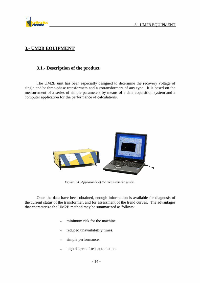
The UM2B unit has been especially designed to determine the recovery voltage of
single and/or three-phase transformers and autotransformers of any type. It is based on the
measurement of a series of simple parameters by means of a data acquisition system and a
computer application for the performance of calculations.
Figure 3-1: Appearance of the measurement system.
Once the data have been obtained, enough information is available for diagnosis of
the current status of the transformer, and for assessment of the trend curves. The advantages
that characterize the UM2B method may be summarized as follows:
minimum risk for the machine.
reduced unavailability times.
simple performance.
high degree of test automation.

3.- UM2B EQUIPMENT
- 15 -
3.2.- System elements
The equipment may be fitted with the following elements and / or accessories:
NOTE: The XX nomenclature indicates different versions, depending on the characteristics
of the equipment. Please consult with your sales person.
REF No DESCRIPTION
UM2BXX UM2B measuring equipment with serial number.
Figure 3-2: Measuring unit.
BEL00 Measuring equipment transport bag.
Figure 3-3: Transport bag.

3.- UM2B EQUIPMENT
- 16 -
CR00 Mains supply cable with ground terminal.
CRS23200
Shielded series cable with DB9 terminal connectors for
communications between the PC and the unit. The cable must be
shielded.
Figure 3-4: Serial cable.
M8AT0L
8-metre long high voltage shielded measuring cables with wide
opening clip pincers at one end and high voltage connectors at the
other. The polarity is indicated by the color of the clips and
connectors: red for positive and black for negative. These must be
shielded.
Figure 3-5: High voltage cables with power clips.

3.- UM2B EQUIPMENT
- 17 -
BCL00 Cable transport bag
Figure 3-6: Transport bag.
SOFUM2BRBWXXX 1CD with equipment control software.
UM2BMUXX The present user manual.
RAFVDM00
Four power sockets protected against voltage surges, differential
currents and overcurrent. This incorporates a voltmeter for direct
verification of the supply voltage indicator of ground connection and
terminals for ground connection.
Figure 3-7: Power Socket.

3.- UM2B EQUIPMENT
- 18 -
MM00 Rigid transport case with reinforced external protection and internal
padded lining of high-density foam rubber.
Figure 3-8: Transport Case.

3.- UM2B EQUIPMENT
- 19 -
3.3.- Physical description of equipment
Figure 3-9 shows a drawing of the UM2B unit, the upper part corresponding to the
front panel and the lower to the rear panel. The function of each element of the unit is
described below.
Figure 3-9: Front and rear panel of the unit.

3.- UM2B EQUIPMENT
- 20 -
1
Test voltage indicator. This acts as a voltmeter, indicating the
voltage being applied to the machine by means of 4 LED
diodes.
2 Power unit connection indicator. This should light up when the
power switch (4) is turned on.
3 Luminous indicator of communications with the PC.
4
Equipment connection switch. This is operated to connect the
equipment to the electrical mains when the PC software so
indicates.
5 Mains input connection. This includes a fuse-holder and a
spare fuse.
6 Unit nameplate.
7 PC communications connector.
8 Connectors for high voltage cables running to equipment being
tested.
The rest of the indicators / warnings appear on the computer screen and will be
described in detail in chapter 5 (Software description).

4.- PREPARATIONS BEFORE TO USE
- 21 -
4.- PREPARATIONS BEFORE TO USE
The UM2B equipment is an automatic, high performance system especially
designed for the assessment of transformer recovery voltage parameter. For
performance of the measurement, the system provides high voltages (up to
2000 Volts d.c.) during testing, this possibly implying serious danger for the
equipment operator if the system is handled incorrectly.
Consequently, IT IS CONSIDERED ESSENTIAL THAT THE
OPERATOR IN CHARGE OF HANDLING AND MAINTAINING
THE EQUIPMENT RECEIVE TECHNICAL TRAINING.
Likewise, all persons performing or witnessing a test should take the necessary safety
precautions, in order to avoid any contact with the parts to be analyzed or forming part of the
measurement system, remaining at some distance from them unless these parts are free from
voltage and grounded.
Measurements performed using the UM2B system are carried out
OFF-LINE. Consequently, prior to beginning the test, THE SYSTEM
SHOULD BE VERIFIED TO BE FREE FROM VOLTAGE/LOAD.
If the equipment is damaged during the warranty period as a result of
inappropriate use, without following the instructions described in this
chapter, the repair may be excluded from the warranty.

4.- PREPARATIONS BEFORE TO USE
- 22 -
4.1.- Precautions in the area of installation
When this instrument is used to test high voltage machines, all the
habitual safety procedures and standards applicable to this type of
machines should be adhered to. Ensure in all cases that the
equipment being tested is completely discharged and grounded
before touching it.
For the safety of the equipment operators or any other worker in the area, as well as
for the integrity of the system itself and to ensure that the measurement results are valid, a
series of precautions should be taken at the test location. These may be summarized as
follows:
Check that the surrounding area is appropriate (without rain or dust storms) and that
it is within the temperature / humidity margins specified for the operation (see
chapter 9: Specifications).
Check that the system supply voltage is within the specific operating
limits (see chapter 9: Specifications) and that it is grounded. This ground
should match with that of the equipment being tested. In case of doubt,
the best thing is to run a thick plaited grounding cable from the system
supply to the equipment tested.
Check that the equipment to be tested is free from its operating voltage or any
remnant voltage (it is most advisable for the machine to have been in a previous short
circuit state before the test).
Position the measuring unit and the control computer close to the equipment being
tested, as shown in Figure 4-1.
Isolate the test area by means of the necessary mechanical elements, as homologated
by the safety department of each company, such as cones, fencing, safety tapes of
different colors located at waist height, etc.

4.- PREPARATIONS BEFORE TO USE
- 23 -
4.2.- Equipment connection
In view of danger that this equipment misuse might entail, ALWAYS
ADHERE TO THE SEQUENCE DESCRIBED BELOW.
For the performance of a test, the measuring unit and control computer should be
located close to the equipment to be analyzed, as shown in Figure 4-1. To start up the
equipment, carry out the following instructions in the order presented (the different elements
of the panels in Figure 3-9 are referred to in brackets):
Figure 4-1: Disposition of the test elements.
- Connection of PC to UM2B.
This connection is accomplished with the series cable, connected to the serial
communications port of the PC.

4.- PREPARATIONS BEFORE TO USE
- 24 -
- Safety check.
The equipment to be measured should be checked to ensure that it is duly
isolated from the external connection lines and completely discharged.
- Connection of high voltage cables to UM2B.
The high voltage cables should first be connected to the unit (8). Next,
choose measurement configuration to perform test. The phases of each
winding (high/low) will be put on short circuit. The phases may be
interconnected by means of bare copper wire if the distances are short and
there is no risk of short-circuiting to ground; otherwise, a proper insulating
cable should be used. Finally, connect positive / negative terminal according
to software indications.
Never remove high voltage connectors during test.
Figure 4-2: Configuration of the test.
V max.: 2000 V dc
I max.: 5 mA
Installation: CAT II
For properly measuring, the cables must be completely stretched until the
measurement point without creases, or anyway, that these have a radius
not under 200 mm.
4.- PREPARATIONS BEFORE TO USE
- 25 -
While measuring, the cables must not be stepped, moved or hit, because
the measurements could be altered, specially when measuring high-
quality insulations, due to the piezoelectric effect of the cable and the
weak measured currents. If it is possible, put these cables parallel and
nearest between them to avoid interferences.
If the shell of the machine to be analyzed is grounded, a check should be
made to ensure that this is the same ground as the one of the PC supply
and the measuring unit. To accomplish this, join these two points with a
plaited cable of adequate cross-section. ALL THE GROUNDS USED
IN TESTING SHOULD BE INTERCONNECTED.
- Connection of UM2B equipment to electrical mains.
This connection is accomplished by running the power cable from (5) to a
mains socket. The supply voltage should be checked to ensure that it is within
the operating limits (see chapter 9: Specifications) and a check should made
to ensure that the socket has an operative ground.
Once the different parts of the equipment have been connected, the PC should be
switched on and the control software executed. Following this, it will be sufficient to follow
the instructions as they appear on the PC screen. Consequently, the UM2B unit should be
turned on when this software so requires (4).
THE UM2B UNIT SHOULD NOT BE TURNED ON UNTIL
THIS IS INDICATED BY THE CONTROL SOFTWARE.
WARNING: If the equipment is used outside manufacturer‟s
specifications, the security could be altered.

4.- PREPARATIONS BEFORE TO USE
- 26 -
4.3.- Disconnection of equipment
ATTENTION!: The cabling should be handled with great care, since
high voltage direct current is involved. There are moments during
the test in which the equipment might be electrically charged at high
voltage, and handling of the cabling or equipment after the test might
be dangerous. Consequently, the habitual safety measures applied to
high voltage installations should be taken into account.
Following performance of the test, the equipment itself will discharge the machine
analyzed. Meanwhile, the computer will show a message indicating that this operation is
being carried out. Consequently, the UM2B unit should be turned off when so indicated
by the control software, following the measurements.
In some transformers, discharging may take several minutes.
Consequently, it is good safety practice to use rubber gloves when
handling the connecting clips.
When requested by the program, the UM2B unit should be disconnected in
accordance with the following steps:
- Switch off the UM2B unit.
- Remove the clips from the equipment being tested.
- Remove the cables from the UM2B. If high voltage connectors are
blocked, unblock them threading security screw that allows remove them.

5.- SOFTWARE DESCRIPTION
- 27 -
5.- SOFTWARE DESCRIPTION
5.1.- Introduction
Along with other units and their respective applications (see Appendix B) the UM2B
constitutes a system for the testing and analysis of electrical machines. Consequently, all
these applications will be launched from a common base application known as the
“Electrical Machine Testing and Analysis System” (Figure 5-1), which is located in the
folder of the same name under Start Programs.
Figure 5-1: Test menu for power transformers.
This screen shows all the tests that may be performed on the different machines and /
or components. If any of the options is shown disabled, it will be because the customer does
not have the corresponding application, which he may acquire at any time (see chapter 8 and
appendix B). The UM2B unit is delivered with the application “Recovery Voltage” and it‟s
available another optional application “Insulation Resistance”.

5.- SOFTWARE DESCRIPTION
- 28 -
In this case, the tab entitled “POWER TRAFO” or “MEASURING TRAFO”, or the
corresponding icon at the top of the screen should be selected. Then click on the icon
corresponding to the UM2B and the Recovery Voltage program will be launched (Figure 5-
2) or the Insulation Resistance (ETPRA) if available. This last one will have the same menu
to Figure 5-2 but without the icon‟s Recovery Voltage and Peak Time.
From this moment both applications: Recovery Voltage and Insulation Resistance
will be described together because of their similarity, detailing when appear the differences
or particularities that offer the Insulating Resistance software (ETPRA).
The main menu of the application offers basically two operating options:
- Test performance (Test).
- Analysis of results (Analysis).
Figure 5-2: Main menu of the UM2B test recovery voltage.
For performance of the test a series of data identifying the machine is required, this
being provided by the operator.
Subsequently, it will be possible to carry out an analysis of the results based on the
voltages measured and the performance of a series of calculations.
Also provided is a series of utilities, such as a file copy assistant or a notepad for test
or analysis events.

5.- SOFTWARE DESCRIPTION
- 29 -
5.2.- Hardware dongle. Configuration menu
The first step to carry out before executing the application, is to place the security
key (dongle) supplied in the parallel port of the PC (LPT1). In the case of not connecting it,
the software will only allow you to carry out analysis of test already performed. When you
connect it, you will be able to carry out a test.
For system configuration, click on "Config" button. Successively, the following
menu will appear (Figure 5-3), in which one will choose the parameters of the system:
Figure 5-3: Configuration Screen.
- Control: the communication with the unit is performed by means of the serial port
(RS-232). You will need to indicate which port will be used, (COM1- COM4), by means of
the existent ring.
- Supply: First of all you will need to select the mains voltage, that will be 115 or
230 V. The frequency of mains voltage will also need to be selected, which will be 50 or
60 Hz, by means of the corresponding ring. The manipulation of this record is just
informative, the user will have to check the proper supply of the unit from it‟s name plate.
- Language: Select one of the languages that are listed. Once selected, after finishing
the program configuration, all the text of the application will change to the selected
language.

5.- SOFTWARE DESCRIPTION
- 30 -
- Date: The format of the date will be selected, be it day - month - year
(DD-MM-AAAA), or month- day- year (MM-DD-AAAA).
- Temperature: Select the units used in the temperature; Fahrenheit (ºF) or
centigrade (ºC).
- Topology: Select the nomenclature of the connection, be it, A – B - C or
U – V - W.
Once the system is configured, press OK button to accept chosen configuration,
or CANCEL, if you choose to refuse it.

5.- SOFTWARE DESCRIPTION
- 31 -
5.3.- Test performance
Measurements performed using the UM2B system are
accomplished OFF-LINE (out of service). Consequently, before
beginning the test, THE EQUIPMENT UNDER TEST SHOULD
BE GUARANTEED TO BE FREE FROM VOLTAGE.
Before beginning the test, the UM2B should already be connected to
the PC by the series cable, BUT THE UNIT SHOULD NOT BE
TURNED ON UNTIL REQUESTED BY THE SOFTWARE; no
operation should be performed on the unit until the program checks
that everything is correct prior to testing.
To perform good and reproductible results, its is recommended that
the device under test had maintained all it’s phases ground
connected the longest possible time before the test. The minimun
recommended length is of an hour or four times the length of the
longest cycle of voltage insertion of a previous test. This way, the
initial conditions are always the same and absorption capacitors (see
figure 2.1) could be considered discharged. Also, if tests with another
measuring equipment are going to be performed, it is therefore
recommended that the first test should be the one with the UM2B
unit.
It is necessary for the PC’s screen saver to be deactivated and the low
consumption mode disabled prior to beginning a test.
To perform a test, click on the “Test” button on the main menu. The system will be
initialized, which may take several seconds. During this time, the message shown in Figure
5-4 will appear.
5.- SOFTWARE DESCRIPTION
- 32 -
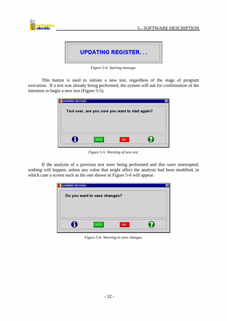
Figure 5-4: Starting message.
This button is used to initiate a new test, regardless of the stage of program
execution. If a test was already being performed, the system will ask for confirmation of the
intention to begin a new test (Figure 5-5).
Figure 5-5: Warning of new test.
If the analysis of a previous test were being performed and this were interrupted,
nothing will happen, unless any value that might affect the analysis had been modified, in
which case a screen such as the one shown in Figure 5-6 will appear.
Figure 5-6: Warning to save changes.
5.- SOFTWARE DESCRIPTION
- 33 -
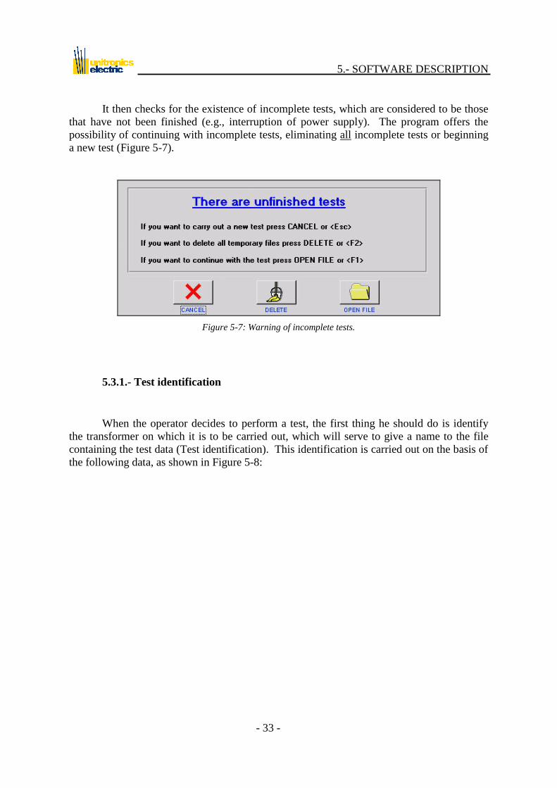
It then checks for the existence of incomplete tests, which are considered to be those
that have not been finished (e.g., interruption of power supply). The program offers the
possibility of continuing with incomplete tests, eliminating all incomplete tests or beginning
a new test (Figure 5-7).
Figure 5-7: Warning of incomplete tests.
5.3.1.- Test identification
When the operator decides to perform a test, the first thing he should do is identify
the transformer on which it is to be carried out, which will serve to give a name to the file
containing the test data (Test identification). This identification is carried out on the basis of
the following data, as shown in Figure 5-8:

5.- SOFTWARE DESCRIPTION
- 34 -
Figure 5-8: Test identification.
- MANUFACTURING No:
Serial number of the transformer being tested.
- MANUFACTURER: The manufacturer is selected from a list. If the manufacturer in question does
not appear, select “other...” to input the name of the new manufacturer
(Figure 5-9). A similar window appears in all cases when the “other…”
option is available.
Figure 5-9: Enter manufacturer’s name.
- MACHINE TYPE:
The type of machine is selected from a list that cannot be modified by the
operator.
5.- SOFTWARE DESCRIPTION
- 35 -
- FUNCTION:
The function of the transformer within the installation.
- PLACE:
The name of the installation (e.g., Brighton thermal power plant) is selected
from a list. If the facility in question does not appear, a new one may be input
using the “other...” option.
- TECHNICAL LOCATION:
The location of the machine within the facility (e.g., pump house) is selected
from a list. If the location in question does not appear, a new one may be
input using the “other...” option.
- USER:
The name of the operator performing the test is selected from a list. If the
operator in question does not appear, a new one may be input using the
“other...” option.
- INSTRUMENT (UM2B):
Serial number of the UM2B with which the test is performed.
- DATE (DD-MM-YY):
Date of the test. The program checks that this date is correct.
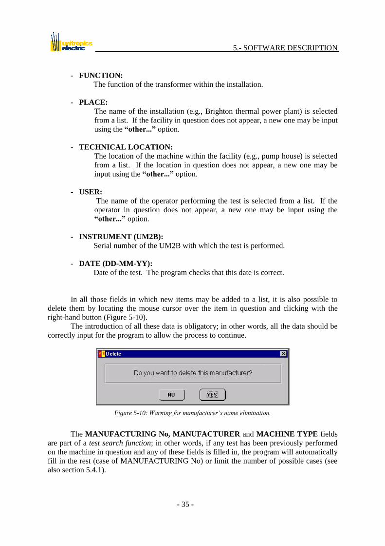
In all those fields in which new items may be added to a list, it is also possible to
delete them by locating the mouse cursor over the item in question and clicking with the
right-hand button (Figure 5-10).
The introduction of all these data is obligatory; in other words, all the data should be
correctly input for the program to allow the process to continue.
Figure 5-10: Warning for manufacturer’s name elimination.
The MANUFACTURING No, MANUFACTURER and MACHINE TYPE fields
are part of a test search function; in other words, if any test has been previously performed
on the machine in question and any of these fields is filled in, the program will automatically
fill in the rest (case of MANUFACTURING No) or limit the number of possible cases (see
also section 5.4.1).
5.- SOFTWARE DESCRIPTION
- 36 -
With the data input in the template, the program will generate a directory with the
following structure:
C:\SAGEN_WIN\Ensayos\TTTFFFFFNNNN....\ where:
TTT = Machine type.
Power transformer: TRP
Distribution transformer: TRD
Current transformer: TRI
Voltage transformer: TRV
FFFFF = Manufacturer‟s code.
The first five letters of the manufacturer‟s name. If this name has
fewer than 5 letters, the rest will be filled in automatically with low
hyphens, until the five characters are completed: “ ” “_”. If the
name input contains any of the characters in brackets (. / \ * ¿ : “),
these will be replaced automatically by the characters shown below,
this occurring only when files are created in the PC, and not as regards
what the operator sees:
. ¬ (Alt Gr + 6)
/ ß (Alt + 225)
\ µ (Alt + 230)
* þ (Alt + 231)
? | (Alt + 221)
: ¶ (Alt + 244)
“ § (Alt +21)
NNN... = Manufacturing No
Identifier of transformer
For example, the tests performed on voltage transformer 123456 of the manufacturer
“Uniravis” will be kept in the following sub-directory:
C:\SAGEN_WIN\Ensayos\TRVUNIRA123456\
and those performed on power transformer 654321 belonging to the company “ARK” in the
sub-directory:

5.- SOFTWARE DESCRIPTION
- 37 -
C:\SAGEN_WIN\Ensayos\TRPARK__654321\
There will be the same number of sub-directories in C:\SAGEN_WIN\Ensayos\ as
there are machines that have been tested. In each sub-directory a series of files will be
generated, which will have a nomenclature structure similar to that of the sub-directories.
These files will have a 3-character extension (0 to 999), and will each contain a test on the
same machine. The files that will be generated are as follows:
TDRTTTFFFFFNNNN···.nnn
This file will be used to record all the data on the complete test, in Excel
format and text mode with tabulators.
medTDRTTTFFFFFNNNN···.nnn This file is used exclusively by the program and contains all the test data. It
cannot be edited by the operator.
TTTFFFFFNNNN···.cab This file is used to record all the technical data on the transformer. It cannot
be edited by the operator.
A temporary file will also be generated automatically in C:\SAGEN_WIN\Ensayos\
whenever a process is completed. This file, which is called
medTDRTTTFFFFFNNNN···.tnn, serves as a back-up in the event of anomalous failure
of the system, such that the program may continue at the last process performed. The file
remains in effect only until the test is successfully performed, as from which moment the
definitive file seen above is generated and this one is deleted.
The software of the UM2B uses this name-based structure to search for
tests, as a result of which THE USER SHOULD NOT ALTER THE
NAMES GENERATED BY THE PROGRAM FOR EACH TEST.
The identification window contains three buttons: (OK), (CANCEL)
and (NEXT). The CANCEL button returns to the main screen without validating
any possible change carried out in the window fields. The OK and NEXT buttons basically
perform the same function, with the difference that the OK button validates the changes
made in the window and returns to the main panel, while the NEXT button also validates the
data but goes on to the next process to be performed. The functionality of these buttons will
be the same in any window in which they might appear.

5.- SOFTWARE DESCRIPTION
- 38 -
5.3.2.- Transformer technical data
This screen (Figure 5-11) is used to input the technical data on the transformer to be
tested. The upper part of the screen shows the name of the file in which the test is to be
stored, along with the data identifying the transformer and input from the previous screen.
All of these appear on a yellow background, which indicates that they are purely for
informative purposes, and cannot be modified.
- TYPE:
Class of transformer used. This appears on the nameplate.
- Transformer/Autotransformer:
This indicates whether the unit is a transformer or an autotransformer.
- No Tertiary/Tertiary:
This indicates whether the transformer has or does not have a tertiary
winding.
- Single Phase/Three-phase:
This indicates whether the transformer is single phase or three-phase.
- Y. OF MANUFACTURING:
Year in which the transformer was manufactured.
- COOLING:
Type of transformer cooling. This may be by oil or dry.
- POWER (MVA):
Maximum power of the transformer in millions of volt-amperes.
- NOMINAL Vdc:
Nominal short-circuit voltage in percentage terms. This is the percentage of
the rated voltage that needs to be applied to the high voltage winding for the
nominal current to circulate through the low voltage winding when the latter
is shorted. This is shown on the nameplate.
- CONNECTION GROUP:
This is the winding connection group for three-phase transformers. By
clicking on the indicator a list of the existing possibilities is shown. For
groups in which „N/n‟ appears, one of the windings has an accessible neutral:

5.- SOFTWARE DESCRIPTION
- 39 -
if the indication is „N‟ (e.g.: YNy0) the high voltage winding has the
accessible neutral, and if „n‟ (e.g.: Dyn5) it is the low voltage winding.
- TERTIARY GROUP:
This indicates whether the transformer has a third winding, in addition to the
high and low voltage windings.
Figure 5-11: Enter the technical data of the transformer.
Other parameters for each of the windings may be selected on the right, such as the
following:
- COMPOUND VOLTAGE (KV):
Nominal voltage between two phases of the winding. In the case of delta
connections, this matches with the simple or phase voltage. For more
information, refer to Figure 5-12.
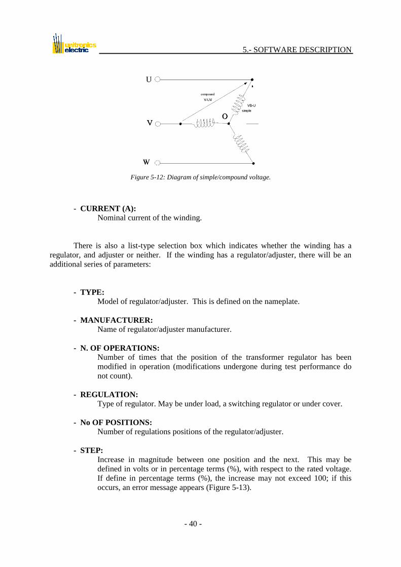
5.- SOFTWARE DESCRIPTION
- 40 -
Figure 5-12: Diagram of simple/compound voltage.
- CURRENT (A):
Nominal current of the winding.
There is also a list-type selection box which indicates whether the winding has a
regulator, and adjuster or neither. If the winding has a regulator/adjuster, there will be an
additional series of parameters:
- TYPE:
Model of regulator/adjuster. This is defined on the nameplate.
- MANUFACTURER:
Name of regulator/adjuster manufacturer.
- N. OF OPERATIONS:
Number of times that the position of the transformer regulator has been
modified in operation (modifications undergone during test performance do
not count).
- REGULATION:
Type of regulator. May be under load, a switching regulator or under cover.
- No OF POSITIONS:
Number of regulations positions of the regulator/adjuster.
- STEP:
Increase in magnitude between one position and the next. This may be
defined in volts or in percentage terms (%), with respect to the rated voltage.
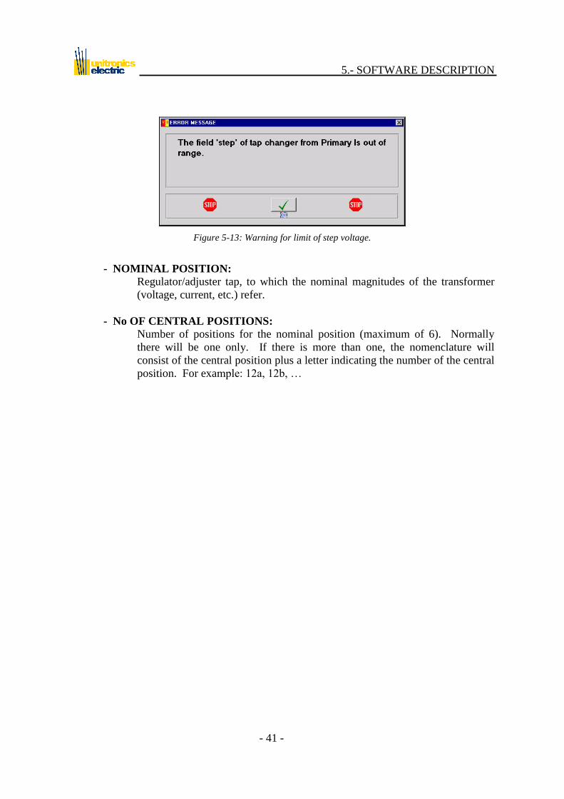
If define in percentage terms (%), the increase may not exceed 100; if this
occurs, an error message appears (Figure 5-13).
5.- SOFTWARE DESCRIPTION
- 41 -
Figure 5-13: Warning for limit of step voltage.
- NOMINAL POSITION:
Regulator/adjuster tap, to which the nominal magnitudes of the transformer
(voltage, current, etc.) refer.
- No OF CENTRAL POSITIONS:
Number of positions for the nominal position (maximum of 6). Normally
there will be one only. If there is more than one, the nomenclature will
consist of the central position plus a letter indicating the number of the central
position. For example: 12a, 12b, …

5.- SOFTWARE DESCRIPTION
- 42 -
5.3.3.- Configuration of measurement
Recovery Voltage Software
This screen (Figure 5-14-a) is used to select the voltage at which the test is to be
performed and the initial cycle time during which this voltage is to be applied (time base),
along with the transformer connection mode (if the measurement is performed between high
and low voltage or between high and tertiary) and the temperature of the transformer.
Depending on the time base selected, there will be a larger or smaller number of
measurement cycles (the longer the time, the smaller the number of cycles). Also indicates,
in function of cycles number and time base, minimum test duration and maximum load time.
Figure 5-14-a: Menu for test configuration (Recovery Voltage).
5.- SOFTWARE DESCRIPTION
- 43 -
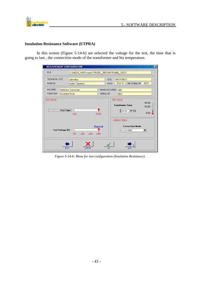
Insulation Resistance Software (ETPRA)
In this screen (Figure 5-14-b) are selected the voltage for the test, the time that is
going to last , the connection mode of the transformer and his temperature.
Figure 5-14-b: Menu for test configuration (Insulation Resistance).
5.- SOFTWARE DESCRIPTION
- 44 -
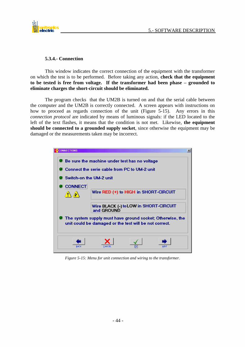
5.3.4.- Connection
This window indicates the correct connection of the equipment with the transformer
on which the test is to be performed. Before taking any action, check that the equipment
to be tested is free from voltage. If the transformer had been phase – grounded to
eliminate charges the short-circuit should be eliminated.
The program checks that the UM2B is turned on and that the serial cable between
the computer and the UM2B is correctly connected. A screen appears with instructions on
how to proceed as regards connection of the unit (Figure 5-15). Any errors in this
connection protocol are indicated by means of luminous signals: if the LED located to the
left of the text flashes, it means that the condition is not met. Likewise, the equipment
should be connected to a grounded supply socket, since otherwise the equipment may be
damaged or the measurements taken may be incorrect.
Figure 5-15: Menu for unit connection and wiring to the transformer.

5.- SOFTWARE DESCRIPTION
- 45 -
When UM2B unit is powered on, the connection will be established between this and
the PC. This may take a few seconds, during which time the program will indicate that it is
attempting to connect to the UM2B unit (Figure 5-16).
Figure 5-16: Message indicating the PC is attempting to establish communications with the unit.
ATTENTION: For correct operation of the equipment, it is very
important that all the conditions listed in this window are met.
Once all the conditions are met, the OK and NEXT buttons will be enabled.
5.- SOFTWARE DESCRIPTION
- 46 -
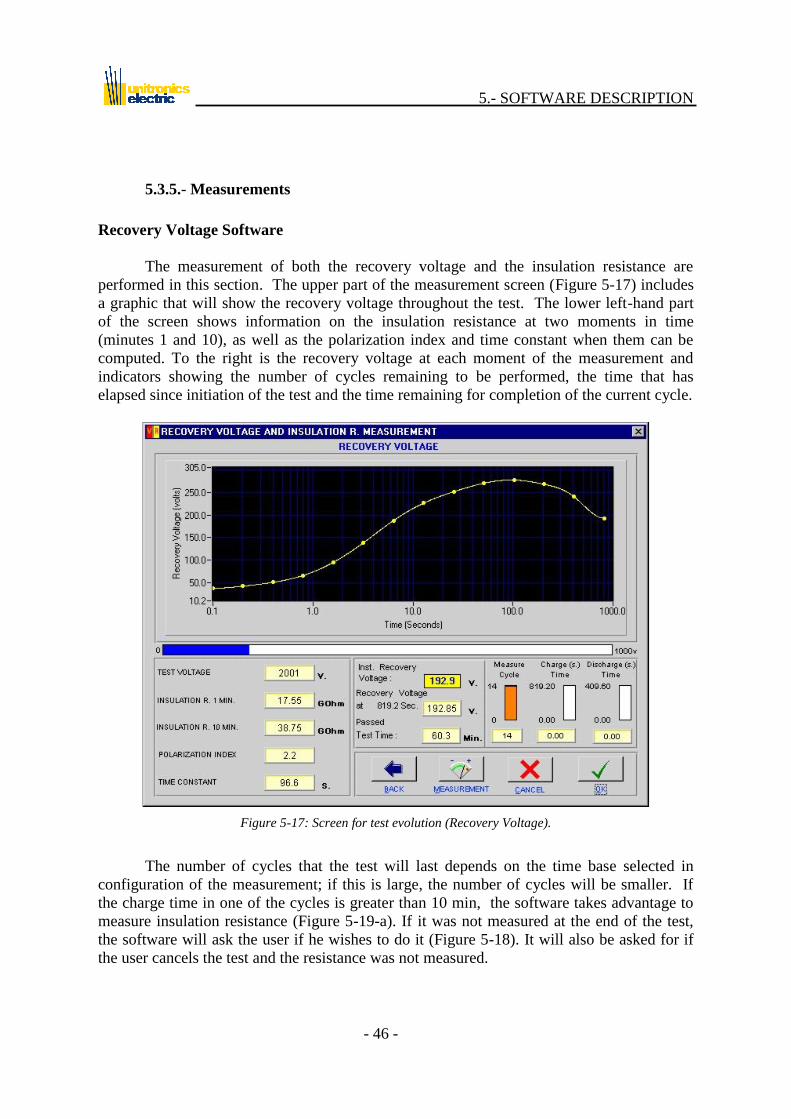
5.3.5.- Measurements
Recovery Voltage Software
The measurement of both the recovery voltage and the insulation resistance are
performed in this section. The upper part of the measurement screen (Figure 5-17) includes
a graphic that will show the recovery voltage throughout the test. The lower left-hand part
of the screen shows information on the insulation resistance at two moments in time
(minutes 1 and 10), as well as the polarization index and time constant when them can be
computed. To the right is the recovery voltage at each moment of the measurement and
indicators showing the number of cycles remaining to be performed, the time that has
elapsed since initiation of the test and the time remaining for completion of the current cycle.
Figure 5-17: Screen for test evolution (Recovery Voltage).
The number of cycles that the test will last depends on the time base selected in
configuration of the measurement; if this is large, the number of cycles will be smaller. If
the charge time in one of the cycles is greater than 10 min, the software takes advantage to
measure insulation resistance (Figure 5-19-a). If it was not measured at the end of the test,
the software will ask the user if he wishes to do it (Figure 5-18). It will also be asked for if
the user cancels the test and the resistance was not measured.

5.- SOFTWARE DESCRIPTION
- 47 -
Figure 5-18: Warning message.
Figure 5-19-a: Measurement Screen (Recovery Voltage).

5.- SOFTWARE DESCRIPTION
- 48 -
Insulation Resistance Software (ETPRA)
In this screen is performed the measurement of insulation resistance. The upper part
of the measurement screen (Figure 5-19-b) includes a graphic that will show the evolution of
the insulation resistance throughout the test. The lower left-hand part of the screen shows
information on the insulation resistance at two moments in time (minutes 1 and 10), as well
as the polarization index and test voltage. To the right are two indicators: one indicates the
complete elapsed time (including the machine‟s discharge time) and the other the time it will
take to measure the insulation resistance. This last one will pause at the moment in which the
unit is performing the measurement. When arriving zero, the test will be over.
Figure 5-19-b: Measurement Screen (Insulation Resistance).

5.- SOFTWARE DESCRIPTION
- 49 -
To initiate measurement, click on the button, and, in case the high or low
voltage of the machine (in function in the connection mode) is inferior than the test voltage
selected by the user, the following warning message will be shown (Figure 5-20):
Figure 5-20: Warning message.
Subsequently, the program will undertake calibration of the UM2B, showing the
message that appears in Figure 5-21 throughout the process. The indicator bar shows the
time last in seconds.
Figure 5-21: Calibration message.
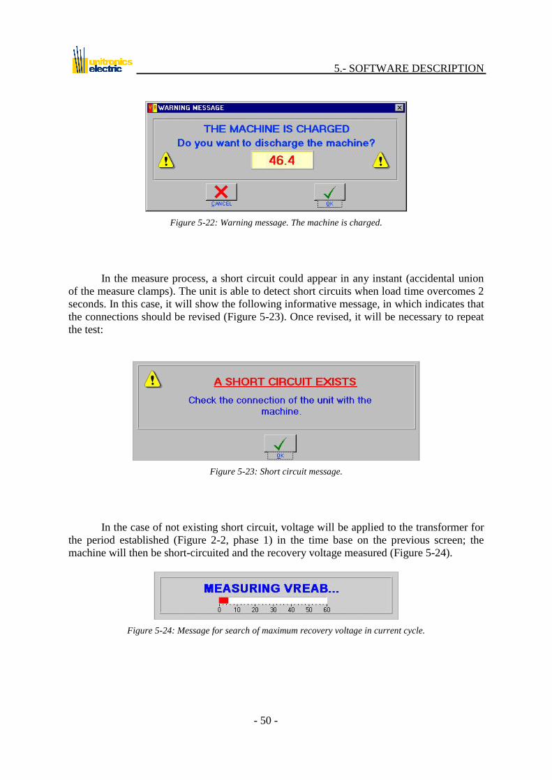
In case the machine is not completely discharged, the unit will detect it, and it will
warn the user with the following message, giving option to discharge it (Figure 5-22). If this
discharge is not performed, the graph of recovery voltage could result altered from the one
that should be drawn, most of all appearing a higher voltage in the first cycles.
5.- SOFTWARE DESCRIPTION
- 50 -
Figure 5-22: Warning message. The machine is charged.
In the measure process, a short circuit could appear in any instant (accidental union
of the measure clamps). The unit is able to detect short circuits when load time overcomes 2
seconds. In this case, it will show the following informative message, in which indicates that
the connections should be revised (Figure 5-23). Once revised, it will be necessary to repeat
the test:
Figure 5-23: Short circuit message.
In the case of not existing short circuit, voltage will be applied to the transformer for
the period established (Figure 2-2, phase 1) in the time base on the previous screen; the
machine will then be short-circuited and the recovery voltage measured (Figure 5-24).
Figure 5-24: Message for search of maximum recovery voltage in current cycle.

5.- SOFTWARE DESCRIPTION
- 51 -
On completion of the measurement, the maximum result will be shown in the
corresponding box and will be plotted on the graph. The transformer will then be
discharged, the message shown in Figure 5-25 appearing throughout the entire process.
Figure 5-25: Discharge message.
Once the measurement has been completed (all the cycles are finished), the program
will undertake the complete discharge of the transformer; during this time, the message
shown in Figure 5-26 will be displayed.
Figure 5-26: Final discharge of the transformer.
If there is no problem, the program will show Figure 5-27 on completion of
measurement for all the cycles, indicating that the test has been completed. The unit will
indicate the end of the test to the user by means of a series of acoustic sounds to claim his
attention. This is specially useful if the user is far from the unit performing another work
while the test evolves.
Figure 5-27: Warning for test end.
The measurement may be cancelled at any moment by clicking on the button.
If this occurs, the program will undertake discharging of the transformer (Figure 5-26), and
will remain ready for a new measurement.
5.- SOFTWARE DESCRIPTION
- 52 -
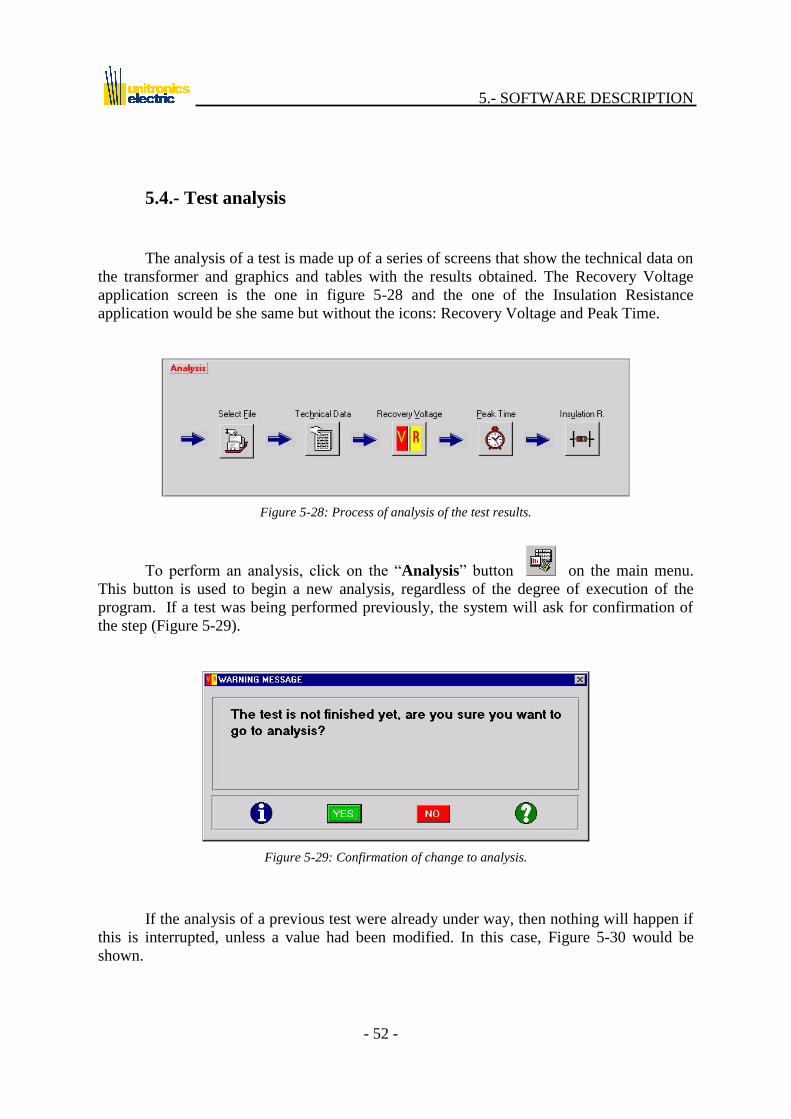
5.4.- Test analysis
The analysis of a test is made up of a series of screens that show the technical data on
the transformer and graphics and tables with the results obtained. The Recovery Voltage
application screen is the one in figure 5-28 and the one of the Insulation Resistance
application would be she same but without the icons: Recovery Voltage and Peak Time.
Figure 5-28: Process of analysis of the test results.
To perform an analysis, click on the “Analysis” button on the main menu.
This button is used to begin a new analysis, regardless of the degree of execution of the
program. If a test was being performed previously, the system will ask for confirmation of
the step (Figure 5-29).
Figure 5-29: Confirmation of change to analysis.
If the analysis of a previous test were already under way, then nothing will happen if
this is interrupted, unless a value had been modified. In this case, Figure 5-30 would be
shown.

5.- SOFTWARE DESCRIPTION
- 53 -
Figure 5-30: Warning for data update.
5.4.1.- Select test file
By clicking on this button, and as long as there are tests in the directory
\SAGEN_WIN\Ensayos\, the test search function shown in Figure 5-31 will appear.
Figure 5-31: Test search.
If the search is performed by manufacturing No, it may be performed manually or
automatically. If automatic, a menu will appear when this control is clicked on, showing the
serial numbers of the machines tested, and the rest of the fields will be filled in
automatically. If the search is performed manually, the serial number has to be input. If any
test on this transformer is found, the rest of the fields will be filled in; otherwise, they will be
left blank, indicating that there is no test on this machine.
If the search is performed by manufacturer and machine type, it will be highlighted
in a gray box in this zone, and when one of these fields is clicked on. A menu will appear
with the manufacturers or types of machines. If when one of these is selected the field is not

5.- SOFTWARE DESCRIPTION
- 54 -
filled in automatically, it will be because no test has been performed on a machine having
the selected characteristics. If the field is filled in, there may be various transformers with
these characteristics, and the one desired should be selected by clicking on the tab of the
manufacturing number.
Once the machine to be analyzed has been selected, click on the button and the
file selector will appear (Figure 5-32); this may be used to select the test to be analyzed for
this machine.
Figure 5-32: Selector of files to analyze.
Following the selection of the test, this is loaded into the memory by clicking twice
on the test itself or on the “Load” button. Prior to doing this, the program checks that it is
actually a UM2B test file; if this is the case, it is loaded in the memory; otherwise, the
program informs that it is an incorrect file (Figure -33) and offers the possibility of choosing
another (Figure 5-32).
Figure 5-33: Warning for incorrect file.

5.- SOFTWARE DESCRIPTION
- 55 -
5.4.2.- Transformer technical data
Once a test has been loaded, the program displays a screen (Figure 5-34) which
shows the data identifying the test in its upper part and technical data on the machine in the
lower. For more information on the meaning of these data, refer to section 5.3.2. Although
these data are merely informative, the operator may change them, with the exception of the
data identifying the test. This is indicated by the background of the indicators: if the
background is yellow, the field cannot be modified; if it is white, the data may be changed.
This is valid for the entire analysis.
The name of the file subject to analysis is shown all the time in the upper part of the
screen.
Figure 5-34: Analysis screen, technical data.
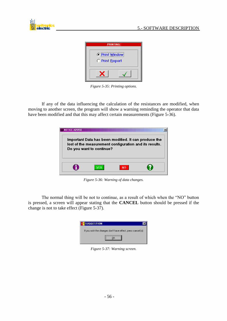
On all screens in which the button appears, there is the possibility of printing
the current screen or the complete test report (Figure 5-35). For more information on reports
printing, refer to section 5.7.
5.- SOFTWARE DESCRIPTION
- 56 -
Figure 5-35: Printing options.
If any of the data influencing the calculation of the resistances are modified, when
moving to another screen, the program will show a warning reminding the operator that data
have been modified and that this may affect certain measurements (Figure 5-36).
Figure 5-36: Warning of data changes.
The normal thing will be not to continue, as a result of which when the “NO” button
is pressed, a screen will appear stating that the CANCEL button should be pressed if the
change is not to take effect (Figure 5-37).
Figure 5-37: Warning screen.

5.- SOFTWARE DESCRIPTION
- 57 -
5.4.3.- Recovery voltage
This screen shows the maximum dots of recovery voltage measured at the different
cycles during the test. As in all the analysis screens (recovery voltage, peak time and
insulation resistance), the upper part shows the name of the file being analyzed and certain
data, such as the time base selected for the test, the transformer temperature, the type of
cooling, type of connection and the voltage at which the test is performed, along with other
data such as the time constant and polarization index.
Below these informative data there is a graphic showing the evolution of the recovery
voltage throughout the test (see: Figure 5-38). To the right of this graphic there are two
columns showing the times at which each recovery voltage sample has been taken and the
corresponding value.
The operator may move through this graphic using the cursors and/or the mouse. As
the cursor is moved, the value of recovery voltage and corresponding time are shown below,
in the right-hand corner.
Figure 5-38: Analysis screen: Recovery diagram. Lineal graph.

5.- SOFTWARE DESCRIPTION
- 58 -
Below the table of values of the graphic there is a selector which may be used to
select the type of curve to be used to display the recovery voltage. Three display modes may
be chosen: Linear curve (Figure 5-38), on which each point sampled is connected to the
adjacent points by a straight line; Interpolated curve (Figure 5-39), where the points are
connected by curves; and Both (Figure 5-40), with the linear and interpolated curves
displayed on the same graphic.
Figure 5-39: Recovery graph: Interpolated plot.
Figure 5-40: Recovery graph: both plot.

5.- SOFTWARE DESCRIPTION
- 59 -
5.4.4.- Peak time
This screen is very similar to the previous one , but instead of showing the recovery
voltage, it is shown the time (a dot) it takes to the dielectric to arrive to each cycle‟s
maximum recovery voltage sample. In this case the operator cannot move around the
graphic, but – as in the previous case – the rise time to the recovery maximum at different
cycles of the test is shown to the right.
Figure 5-41: Analysis: Recovery peak time.
5.- SOFTWARE DESCRIPTION
- 60 -
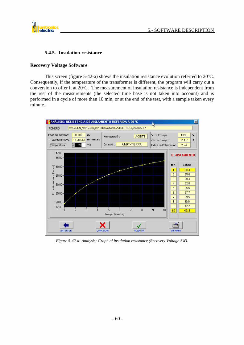
5.4.5.- Insulation resistance
Recovery Voltage Software
This screen (figure 5-42-a) shows the insulation resistance evolution referred to 20ºC.
Consequently, if the temperature of the transformer is different, the program will carry out a
conversion to offer it at 20ºC. The measurement of insulation resistance is independent from
the rest of the measurements (the selected time base is not taken into account) and is
performed in a cycle of more than 10 min, or at the end of the test, with a sample taken every
minute.
Figure 5-42-a: Analysis: Graph of insulation resistance (Recovery Voltage SW).
5.- SOFTWARE DESCRIPTION
- 61 -
Insulation Resistance Software (ETPRA)
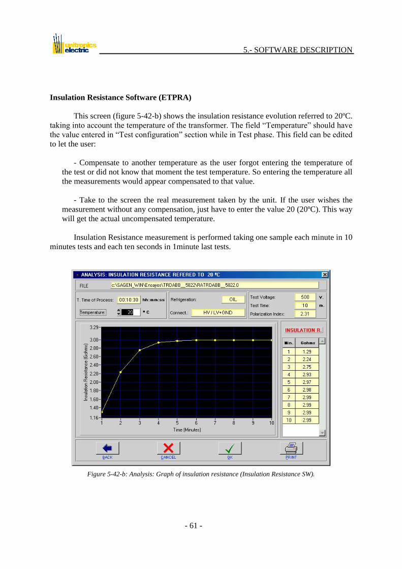
This screen (figure 5-42-b) shows the insulation resistance evolution referred to 20ºC.
taking into account the temperature of the transformer. The field “Temperature” should have
the value entered in “Test configuration” section while in Test phase. This field can be edited
to let the user:
- Compensate to another temperature as the user forgot entering the temperature of
the test or did not know that moment the test temperature. So entering the temperature all
the measurements would appear compensated to that value.
- Take to the screen the real measurement taken by the unit. If the user wishes the
measurement without any compensation, just have to enter the value 20 (20ºC). This way
will get the actual uncompensated temperature.
Insulation Resistance measurement is performed taking one sample each minute in 10
minutes tests and each ten seconds in 1minute last tests.
Figure 5-42-b: Analysis: Graph of insulation resistance (Insulation Resistance SW).

5.- SOFTWARE DESCRIPTION
- 62 -
5.5.- Test duplication assistant
Given the number of files involved in the test, and in order to facilitate the work of
the operator as regards their storage, the program incorporates a utility that allows tests to be
copied to a location different from that originally used by the program, with the possibility
for both the point of origin and the destination to be fixed, flexible or network units. When
the is pressed, Figure 5-43 will appear.
Figure 5-43: Assistant for test duplication.
In “Origin” the name of the test file to be recorded is selected, and in “Destination”
the directory in which the test is to be recorded.
5.- SOFTWARE DESCRIPTION
- 63 -
5.6.- Remarks page
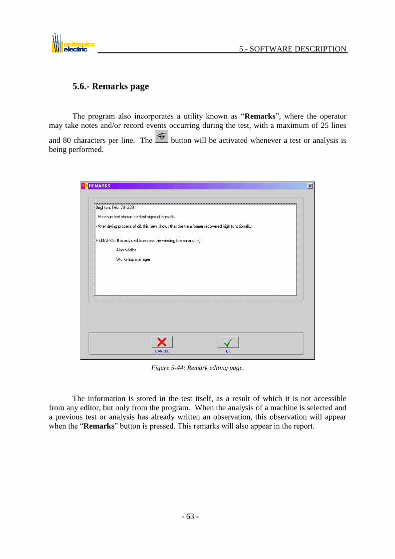
The program also incorporates a utility known as “Remarks”, where the operator
may take notes and/or record events occurring during the test, with a maximum of 25 lines
and 80 characters per line. The button will be activated whenever a test or analysis is
being performed.
Figure 5-44: Remark editing page.
The information is stored in the test itself, as a result of which it is not accessible
from any editor, but only from the program. When the analysis of a machine is selected and
a previous test or analysis has already written an observation, this observation will appear
when the “Remarks” button is pressed. This remarks will also appear in the report.

5.- SOFTWARE DESCRIPTION
- 64 -
5.7.- Reports printing
From the button located on the main menu it is possible to print a test report.
Throughout this process the program shows a message, asking the operator to wait. The
report will be printed at the predetermined Windows printer.
Figure 5-45: Message of printing.
Reports consist of 3 pages in the Recovery Voltage application and 2 pages for the
Insulation Resistance application. The appearance of a report is described below:
Recovery Voltage:
- The 1st page includes identification data and technical data on the transformer tested.
Figure 5-46-a.
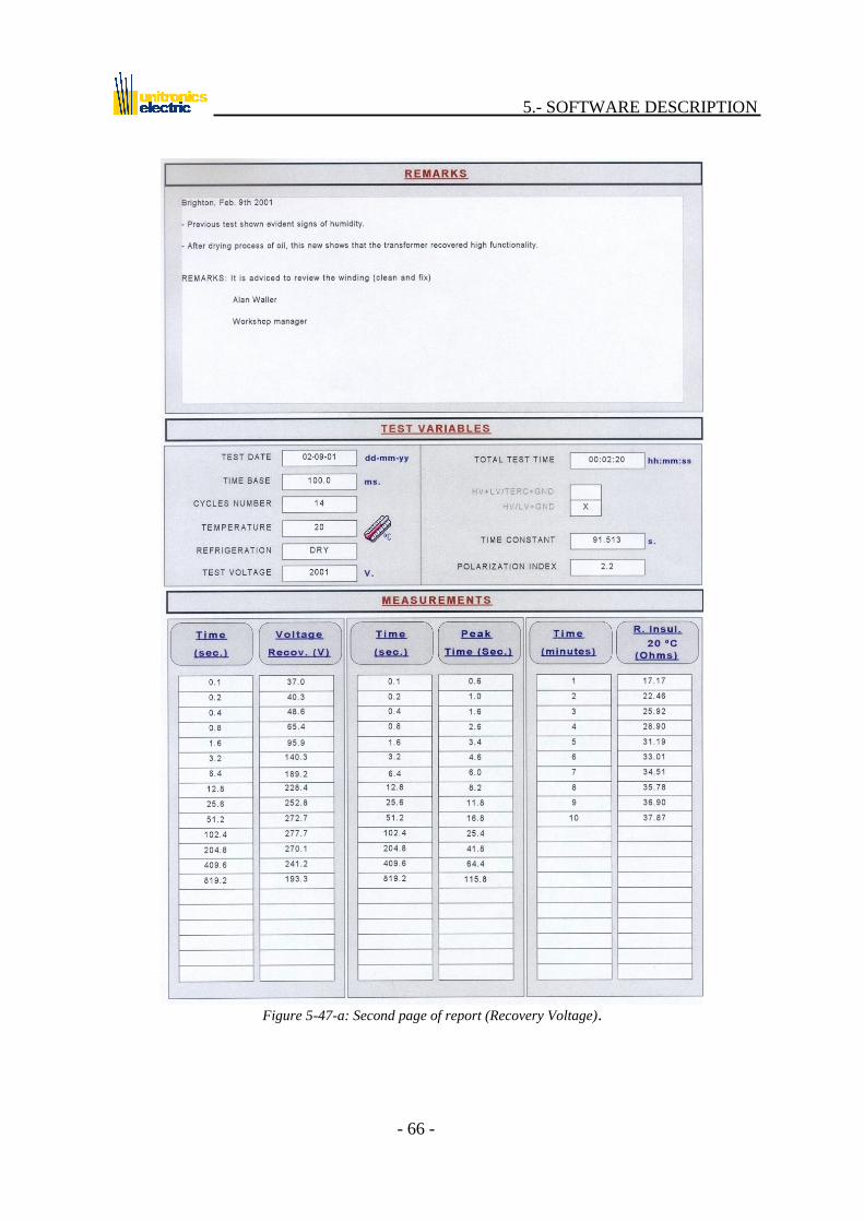
- The 2nd page includes the observations made during the test or analysis in its upper
part and, in the middle, a brief summary of the measures performed. In the lower
part are shown the measurements taken at different moments during the test (each
sample time is twice the previous one, as from the time base established). Figure 5-
47-a.
- The 3rd page shows the recovery voltage, rise time and insulation resistance graphs.
Figure 5-48.
Insulation Resistance:
- The 1st page includes identification data and technical data on the transformer tested.
Figure 5-46-b.
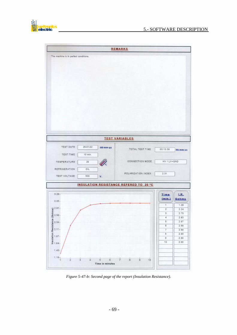
- The 2nd page includes the observations made during the test or analysis in its upper
part and, in the middle, a brief summary of the measures performed. In the lower part
is shown the graph of insulation resistance. Figure 5-47-b.

5.- SOFTWARE DESCRIPTION
- 65 -
Figure 5-46-a: First page of the report (Recovery Voltage).
5.- SOFTWARE DESCRIPTION
- 66 -
Figure 5-47-a: Second page of report (Recovery Voltage).

5.- SOFTWARE DESCRIPTION
- 67 -
Figure 5-48: Third page of report (Recovery Voltage).

5.- SOFTWARE DESCRIPTION
- 68 -
Figure 5-46-b: First page of the report (Insulation Resistance).
5.- SOFTWARE DESCRIPTION
- 69 -
Figure 5-47-b: Second page of the report (Insulation Resistance).

5.- SOFTWARE DESCRIPTION
- 70 -
5.8.- About …
By clicking on this button, a window will appear (Figure 5-49) showing the
following:
- Data on the license.
- Data on the version of the program.
Figure 5-49: Cover screen.
If an internet connection is available, when clicking the UNITRONICS web page, the
software will load the predetermined windows explorer with our web page. This cover
screen also appears when the program is executed.
5.- SOFTWARE DESCRIPTION
- 71 -
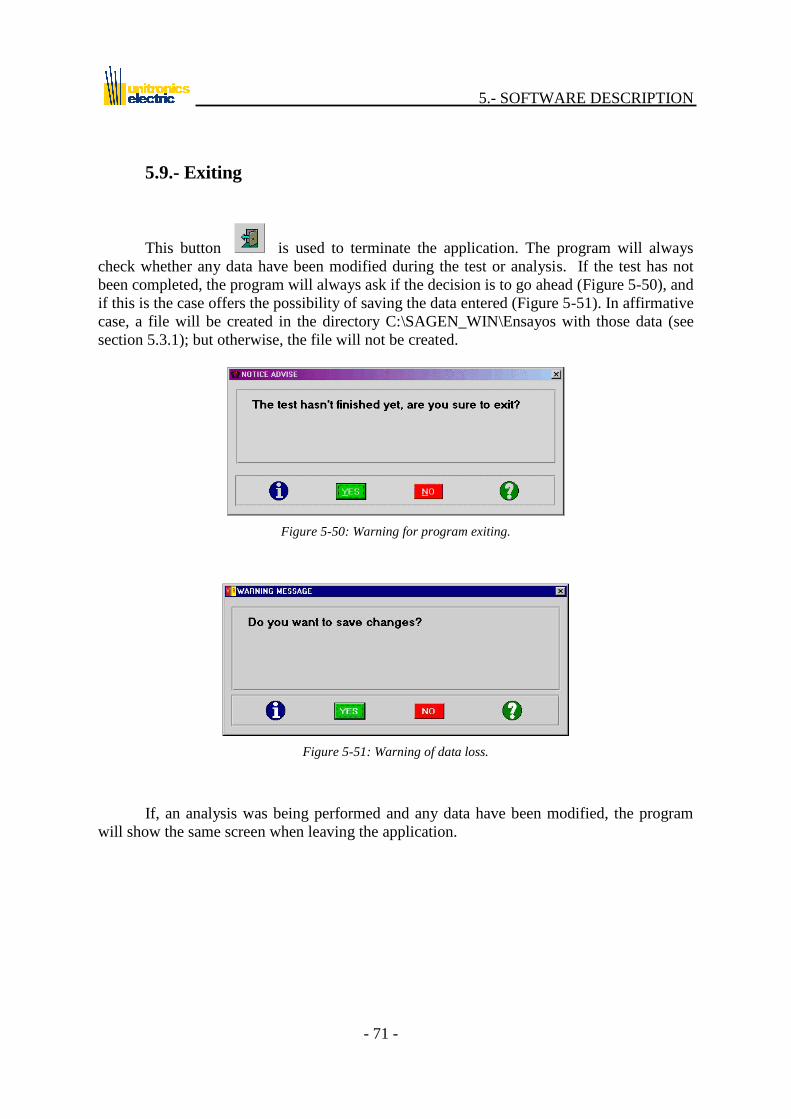
5.9.- Exiting
This button is used to terminate the application. The program will always
check whether any data have been modified during the test or analysis. If the test has not
been completed, the program will always ask if the decision is to go ahead (Figure 5-50), and
if this is the case offers the possibility of saving the data entered (Figure 5-51). In affirmative
case, a file will be created in the directory C:\SAGEN_WIN\Ensayos with those data (see
section 5.3.1); but otherwise, the file will not be created.
Figure 5-50: Warning for program exiting.
Figure 5-51: Warning of data loss.
If, an analysis was being performed and any data have been modified, the program
will show the same screen when leaving the application.
5.- SOFTWARE DESCRIPTION
- 72 -
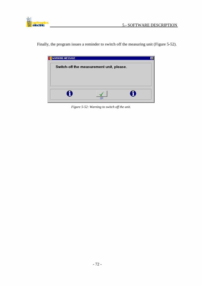
Finally, the program issues a reminder to switch off the measuring unit (Figure 5-52).
Figure 5-52: Warning to switch off the unit.

6.- EQUIPMENT MAINTENANCE
- 73 -
6.- EQUIPMENT MAINTENANCE
In view of the special characteristics of the equipment, this MAY ONLY BE
REPAIRED BY AUTHORIZED TECHNICAL PERSONNEL. As
mentioned in other sections, because of the special danger involved in
handling high voltages with the equipment, the maintenance personnel
repairing, adjusting and calibrating the equipment should be duly qualified
and trained.
Opening of the equipment by non-authorized personnel implies cancellation of the
warranty period.
The equipment does not contain any internal elements to be handled by
the operator, and SHOULD IN NO CASE BE OPENED, DUE TO
THE SERIOUS DANGER OF ELECTRICAL SHOCK.
The maintenance of the equipment is very straightforward and consists simply of
keeping it in good condition externally and making sure the cables supplied are also in good
condition. If the fuse blows, it should be replaced with one of identical characteristics, as
described in section 6.4 (Replacement of fuses). If a fuse should blow continuously, the
equipment should be sent for repair (see section 8.1: Return for calibration/repair).
In order to maintain its values of accuracy, the equipment should be calibrated at
least once a year.
Special care should be taken to prevent the unit from getting wet, and it should be
protected against rain if necessary. In the event of extreme levels of humidity or
temperatures outside the margins, the measures provided by the equipment will not be valid,
and it will be necessary to wait for the equipment to regain its operability. For example,
leave it to dry if it has got wet. Likewise, changes in the situation of the equipment,
especially if stored, may cause rapid variations in temperature causing humidity to appear as
a result of condensation.

6.- EQUIPMENT MAINTENANCE
- 74 -
6.1.- Cleaning of equipment
ATTENTION: Always turn off the power switch (4) and disconnect
the supply cables from the socket (5) before cleaning the equipment.
Use the following to clean the equipment and cables:
a soft dry cloth, if the equipment is not particularly dirty.
a cloth soaked in a diluted neutral cleaning product if the equipment is very dirty or
has been in store for some time. After checking that the shell is completely dry, use a
soft dry cloth to clean.
ATENTION: Never use alcohol or any other abrasive product to
clean the shell, since this may cause damage or decolouring.
6.- EQUIPMENT MAINTENANCE
- 75 -
6.2.- Care of cables
The UM2B unit is capable of producing high voltages, as a result of
which THE CABLES SHOULD BE IN PERFECT ORDER, TO
AVOID THE DANGER OF ELECTRICAL SHOCK OR ERRORS
AND INACCURACIES IN MEASUREMENT.
The cables and their condition should be periodically checked in order to detect
beforehand any deterioration or breakage that might cause situations of danger for the
operators and/or malfunctioning of the equipment. If the cables are damaged, they should be
sent for repair to an authorized technical service or new cables should be acquired (see
chapter 8). This is applicable also to the cable and unit connectors.
Special care should be taken with the serial cable for connection of the PC, since it is
in charge of controlling the unit.
It is very important not to tread on or move the cables during testing,
since this might alter the measurements, especially at low current values
(very high measured resistances).
For properly measuring, the cables must be completely stretched until the
measurement point without creases, or anyway, that these have a radius
not inferior than 200 mm.
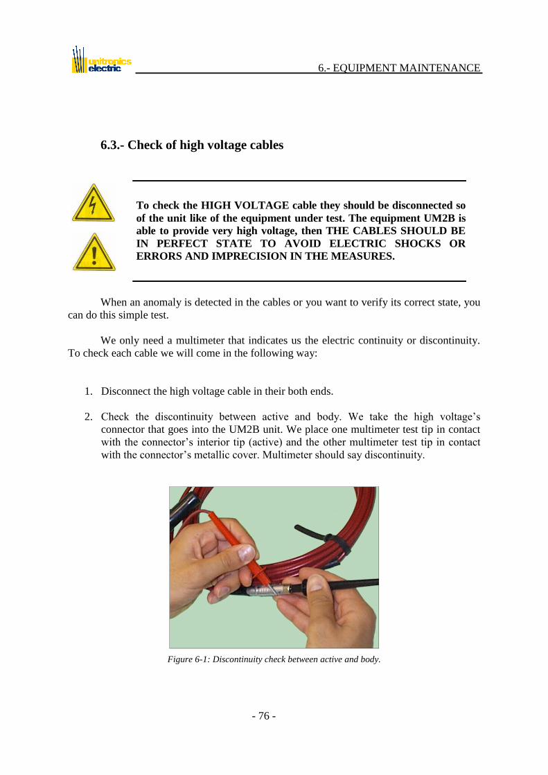
6.- EQUIPMENT MAINTENANCE
- 76 -
6.3.- Check of high voltage cables
To check the HIGH VOLTAGE cable they should be disconnected so
of the unit like of the equipment under test. The equipment UM2B is
able to provide very high voltage, then THE CABLES SHOULD BE
IN PERFECT STATE TO AVOID ELECTRIC SHOCKS OR
ERRORS AND IMPRECISION IN THE MEASURES.
When an anomaly is detected in the cables or you want to verify its correct state, you
can do this simple test.
We only need a multimeter that indicates us the electric continuity or discontinuity.
To check each cable we will come in the following way:
1. Disconnect the high voltage cable in their both ends.
2. Check the discontinuity between active and body. We take the high voltage‟s
connector that goes into the UM2B unit. We place one multimeter test tip in contact
with the connector‟s interior tip (active) and the other multimeter test tip in contact
with the connector‟s metallic cover. Multimeter should say discontinuity.
Figure 6-1: Discontinuity check between active and body.

6.- EQUIPMENT MAINTENANCE
- 77 -
3. Check the continuity between cable ends. We take the high voltage's connector that
goes into the UM2B unit and the clip of the other cable end. We place one
multimeter test tips in contact with the connector's interior tip (active) and the other
multimeter test tips in contact with the clamp that is in the other cable end. The
multimeter should say continuity.
Figure 6-2: Continuity check between cable ends.
4. Previous checks could be performed by the user, but it should also be checked
dielectric rigidity and insulation resistance of the cable should they be damaged. This
two last verifications only could be performed by the technical service.

6.- EQUIPMENT MAINTENANCE
- 78 -
6.4.- Replacing fuse
ATTENTION: Before changing the fuse, ALWAYS unplug the
power cable. Always use fuses of the value and type specified (see chapter 9: Specifications).
In order to avoid possible supply voltage peaks that might damage the UM2B, the
unit incorporates a fuse, housed in the lower part of the mains connector (5). The fuse-
holder may be slid out by hand or using a small screwdriver. Inside (inner) is the operating
fuse and, in an adjacent compartment (outer), a spare.
The very arrangement of the fuse-holder makes it necessary to disconnect
the power cable. Nevertheless, great care should be taken to ensure
safety, and the cables should be disconnected from the equipment being
tested. Also, the UM2B should be moved away from this equipment.
After having carried out the aforementioned safety processes, replace the fuse as
follows:
1 Turn off the switch on the rear panel
2 Disconnect the cables from the equipment being tested.
3 Disconnect the power cable.
4 Open the fuse-holder.
5 Remove the blown fuse (the inner one).
6 Insert the adequate spare fuse.
7 Close the fuse-holder.

6.- EQUIPMENT MAINTENANCE
- 79 -
6.5.- Storage and transport
Changes in the location of the equipment, especially if in store, may
cause rapid variations in temperature that may cause humidity to appear
inside the equipment. This may give rise to erroneous readings or to
short-circuiting in the worst of cases.
Before storing the equipment it is advisable to clean it. Likewise, it is recommended
that all the different elements of the equipment be kept in appropriate storage containers.
The place chosen for storage of the equipment should:
- Not be exposed to direct sunlight.
- Not be exposed to high levels of dust.
- Not be exposed to high levels of humidity.
- Not be exposed to active gases.
- Not be exposed to extreme temperatures.
The recommended conditions for storage are describe in the system specifications
(See chapter 9.3 Specification).
In areas of very high levels of humidity desiccant bags should be used.
If the equipment has been in storage for a very long period of time, it is
advisable to send it to an authorized technical service for calibration.
When transporting the equipment for the performance of tests in different locations,
appropriate transport containers should be used. Likewise, the equipment should not be
subjected to continuous vibrations or to knocks.
Transport should be accomplished under the storage conditions recommended above.

8.- TECHNICAL SUPPORT
- 80 -
7.- TROUBLESHOOTING
SYMPTOM PROBLEM SOLUTION
The power switch (4) is turned on
but the power indicator (2) does not
light up.
Power cable not properly
connected or there is no
power supply.
Connect properly or
check the supply.
The fuse has blown.
Replace fuse (see
section 6.4). If the
problem persists, send
the equipment to an
authorized technical
service.
The equipment is faulty.
Send the equipment to
an authorized technical
service.
There is voltage in the cables but
none of the test voltage indicating
LED‟s (1) lights up.
One of the indicators has
blown.
Send the equipment to
an authorized technical
service.
The equipment is faulty.
Send the equipment to
an authorized technical
service.
One external equipment
sets his voltage on the
cables.
Review the
measurement‟s
conditions and that the
machine is fully
discharged.
The equipment generates voltage but
this is not present in the cables.
The high voltage cables are
not properly connected.
Connect properly
changing previously to
zero the voltage.
The high voltage cables are
in poor condition.
Contact an authorized
technical service.
The equipment is faulty.
Send the equipment to
an authorized technical
service.

8.- TECHNICAL SUPPORT
- 81 -
SYMPTOM PROBLEM SOLUTION
On executing the program, the Test
option is disabled.
The hardware key dongle is
not in place.
Place the key in the
parallel port of the PC,
suitably oriented.
Not has installed the file of
the diskette key
Install the program
inserting the diskette
key when concluding
the installation again.
The connecting cable is connected
between the UM2B and the PC, but
the connections screen (Section
5.3.4) indicates the contrary
The series cable is not
properly connected.
Connect properly or
review in
“configuration” if the
COMX port is the
correct one.
The serial cable is
damaged.
Contact an authorized
technical service.
The message: “UM2B does not
respond” appears on the screen
The unit is not turned on. Turn on the unit.
The serial cable is not
properly connected.
Connect properly or
review in
“configuration” if the
COMX port is the
correct one.
Short-circuit is detected during the
test
Measurement cables are
damaged.
Check measurement
cables.
Equipment under test is
damaged.
If proper, repeat the test
to secure the fault.
Short circuit cables among
phases of every winding are
in contact with chassis or
its isolation is deficient.
Review the wiring.
Irregularities are detected in the
measurement
Short circuit cables among
phases of every winding are
in contact with chassis or
its isolation is deficient.
Review the wiring.
Cables were stepped,
damaged or treaded.
Repeat the test and
check that cables are not
threaded or moved.

8.- TECHNICAL SUPPORT
- 82 -
SYMPTOM PROBLEM SOLUTION
Irregularities are detected in the
measurement.
Machine with residual
charges.
Restart the test
grounding the phases
the recommended time.
Equipment under test is
damaged or has any
insulation failure.
If proper, repeat the test
to secure the fault.
The message: “A SHORT CIRCUIT
EXIST. Check the connection of the
unit with the machine ” appears on
the screen.
The current that circulates
on measurement cables is
very high (delayed
measurement bigger than
3mA) and it is possible that
a short circuit exists in the
machine to measure,
measure connections or
cables of high.
Machine to test:
Damaged machine.
Insulation Resistance is
very low.
Measure connections:
Check that test clamps
are not in short circuit
or that the connections
between bushing and
chassis are properly
insulated.
High voltage Cables:
Check high voltage
cables according to the
section 6.3.
Table 7-1
The numbers in brackets refer to Figure 3-9 (section 3.3).
To contact an authorized technical service or return the equipment, refer to section 8.

8.- TECHNICAL SUPPORT
- 83 -
8.- TECHNICAL SUPPORT
Please provide the following information when contacting our technical service:
- Equipment model.
- Serial number shown on rear panel.
- Description of fault.
- Name and telephone number of the operator in charge of the equipment and of a
person responsible for it.
8.1- Return for calibration/repair
If, after having revised chapter 7 (Troubleshooting) the equipment is concluded to
need repair / calibration, it is essential that the following instructions are adhered to:
1. Copy and fill in the sheets that appear on the following pages and attach them
to the equipment.
2. Pack the equipment or accessories using an appropriate transport container.
When returning the equipment for repair, the most appropriate thing is to send the
complete system; i.e., the measuring unit and cables. In any case, contact the technical
service.

8.- TECHNICAL SUPPORT
- 84 -
CLIENT DATA
COMPANY: Client No:
Address:
City: P.C.: Province:
Contact person: e-mail:
Telephone: Fax:
EQUIPMENT DATA
UM2B serial No:
Date of acquisition:
Date of last adjustment/calibration:
Date of last revision/repair:
Reason for returning
Calibration Calibration certificate required
Repair
(Fill in only in case of problems)
Is the equipment under warranty?
Yes
No
Date on which fault occurred:
Fault detected in equipment
Power LED does not light up
One of the test voltage indicator LED‟s does not light up
Fuse has blown repeatedly
No connection established between PC and equipment.
PC communications cable deteriorated
High voltage cables deteriorated
Equipment broken down
Others
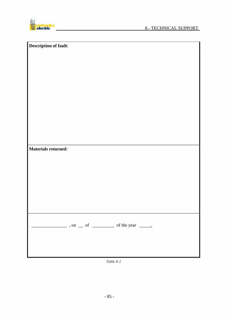
8.- TECHNICAL SUPPORT
- 85 -
Description of fault:
Materials returned:
, on of of the year .
Table 8-1
8.- TECHNICAL SUPPORT
- 86 -
8.2.- Ordering spares
Please contact the Sales Department.
8.3.- Observations
The UM2B equipment has been developed and tested under the same conditions and
in the same installations as those in which it will operate. Nevertheless, it is always good to
gain insight into the degree of satisfaction of the customer and to know what new
performance characteristics he would like to see or which he would eliminate, with a view to
developing future system hardware / software improvements. If you have any observation /
suggestion to make as regards the software, hardware, cabling, operation, characteristics,
etc., please photocopy the following 2 sheets, fill them in and send them to the
corresponding Sales Department.

8.- TECHNICAL SUPPORT
- 87 -
COMPANY: Customer No:
Address:
City: P.C.: Province:
Contact person: e-mail:
Telephone: Fax:
UM2B serial No:
Date of acquisition:
Degree of satisfaction
Very satisfied Satisfied Dissatisfied
Fairly satisfied Not very satisfied Very dissatisfied
What safety elements would you add?
What new calculations should it perform?

8.- TECHNICAL SUPPORT
- 88 -
What standard/optional elements would you add?
What elements would you remove?
What defects does the system have?
, on of of the year .
Table 8-2

8.- TECHNICAL SUPPORT
- 89 -
8.4.- Authorized representatives and technical services
UNITRONICS:
- Sales Department:
UNITRONICS
Sales Department
Avenida Fuente Nueva. 5
28709 San Sebastián de los Reyes
Madrid, SPAIN.
Tel.: +34-91-540 01 25
Fax: +34-91-540 10 68
URL: http://www.unitronics-electric.com
- Technical Service:
UNITRONICS
Technical Service
Avenida Fuente Nueva. 5
28709 San Sebastián de los Reyes
Madrid, SPAIN.
Tel.: +34-91-540 01 25
Fax: +34-91-653 98 10
URL: http://www.unitronics-electric.com

9.- SPECIFICATIONS
- 90 -
9.- SPECIFICATIONS
9.1.- Electrical.
Power requirements: Depending on version:
230V~ ±10% 50/60 Hz ± 5%
115V~ ±10% 50/60 Hz ± 5%
Installation Category II, as to IEC 664-1
Note: The power configuration of the units is fixed from manufacturing.
Consumption: 60 VA (máx.)
Fuses
Location Name Supply Value and kind
Replaceable by
operator. Rear Panel FUS 1
115 V 630 mA T
250 Vac (20x5)
230 V 315 mA T
250 Vac (20x5)
Non Replaceable
by operator
Microcontroller F1
--- 630 mA T
250 Vac TR5 F2
Main Board
F1 115 V
500 mA T
250Vac TR5
230 V 250 mA T
250Vac TR5
F2 115 V
250 mA T
250Vac TR5
230 V 160 mA T
250Vac TR5
F3 --- 160 mA F
250 Vac TR5
F4 --- 160 mA F
250 Vac TR5
F5 ---
200 mA T
250Vac TR5 F6
F7 ---
315 mA T
250Vac TR5 F8
Table 9-1: Fuses required.
All fuses must be homologated and approved for 250 Vac.

9.- SPECIFICATIONS
- 91 -
9.2.- Technical characteristics:
Dimension Value Unit
Length 40 Cm
Width 45 Cm
Height 13.5 Cm
Weight 10 Kg
Table 9.2: Technical characteristics..
9.3.- Measurement Scales.
Technical specifications:
Characteristic Conditions Range Accuracy Resolution
Programmed and generated
test voltage
500V/1000V/1500V/
2000V Max. current 5 mA
1% 1 digits 1V
Test voltage measurement 0 ... 2000 V 1% 3 digits 1V
Recovery voltage
measurement 0 ... 1000 V 3% 3 digits 1V
Isolation measurement
@ 2000 V 1M ... 100 G 3% 3 digits
@ 2000 V 100 G ... 200 G 5% 3 digits
@ 2000 V 200 G ... 2 T 20% 3 digits
Operation temperature 5 - 35ºC
41 – 95 ºF
Operation humidity 10 - 80%
Storage temperature 5 - 75ºC
41- 167 ºF
Storage humidity 5 - 80%
Table 9-3: Unit specifications.
“In determined conditions of presence of transitory phenomenon with respect to earth it may appear
variations in the measure. Then, the test should be re-initialized or repeated.”
The equipment complies with EU Directives applicable to electric and
electronic equipment destined to industrial environments with category II of
installation.

9.- SPECIFICATIONS
- 92 -
9.4.- Minimum control PC requirements
PC: Based on Pentium 200 MHz processor or better.
Operating System: MS Windows 95, MS Windows 98 or MS Windows NT 4 (with
Service Pack 4 or better).
RAM: 32 MB RAM.
VGA colour monitor.
Floppy disk drive
CD-ROM drive.
9.5.- Additional specifications
Other characteristics:
- Power on indicator.
- Luminous test voltage indicator (4 values).
- Luminous indicator of active communication with PC.
- Control of output voltage by use of programmable voltage source controlled from
PC.
Parameters used:
Recovery voltage.
Insulation resistance.
Polarization index.
Time constant.

APPENDIX B.- CONTROL SOFTWARE
- 93 -
APPENDIX A.- “CE” CONFORMITY DECLARATION

APPENDIX B.- CONTROL SOFTWARE
- 94 -
APPENDIX B.- CONTROL SOFTWARE INSTALLATION
The documentation referred to the control software installation manual UM2B can be
found in file SETUP_TR_ING.

APPENDIX C.- OTHER UNITRONICS EQUIPMENTS
- 95 -
APPENDIX C.- OTHER UNITRONICS EQUIPMENT
UNITRONICS provides a set of tools oriented towards the predictive maintenance of
electrical installations that use common hardware and specific software applications for the
performance of different measuring functions.
All the software applications that make up this set have been developed by
UNITRONICS with a view to facilitating maintenance tasks; consequently, the different
programs completely guide the actions of the operator, without the need for the latter to
have in-depth computer knowledge. Subsequently, during the results and trends analysis
phase, the software itself sometimes provides an initial, direct and basic evaluation of the
tests performed.
At the same time, and because of the importance of correct data management, all the
measurements performed using the set of tools are encompassed in a common database,
such that recovering the tests performed on any machine is a simple matter.
All the hardware and applications have been developed by the UNITRONICS
Design Department, thus providing a guaranteed maintenance service. In developing all
these systems, actual tests have been carried out at the same installations in which the
equipment is later to operate, thus ensuring suitable operation and leaving open the
possibility for future modifications based on the experience of the users of our equipment.
The availability of different applications on one same hardware support implies a
series of advantages with respect to traditional instrumentation, the following being
particularly outstanding:
- Unification of measuring systems.
- Common database for all tests.
- Hardware items common to all the systems.
- Reduction of instrumentation costs.
- Ease in handling, guided operation.
- Instructions and menus in English.
- Straightforward maintenance and possibility for modifications.
- Graphic results display.
- Preliminary automatic results assessment.
- Trends analysis.
- Simplification of calculations.

APPENDIX C.- OTHER UNITRONICS EQUIPMENTS
- 96 -
C.1.- Available applications
EDAIII: analysis of motor and alternator insulations (Figure C-1).
Figure C-1: Photograph of EDAIII equipment.
ETP: evaluation of power transformers.
UM1B: measurement of transformation ratio (Figure C-2).
Figure C-2: Photograph of UM1B equipment.

APPENDIX C.- OTHER UNITRONICS EQUIPMENTS
- 97 -
UM2B: measurement of recovery voltage and insulation (Figure C-3).
Figure C-3: Photograph of UM2B equipment.
UM3B: measurement of winding resistance (Figure C-4).
Figure C-4: Photograph of UM3B equipment.
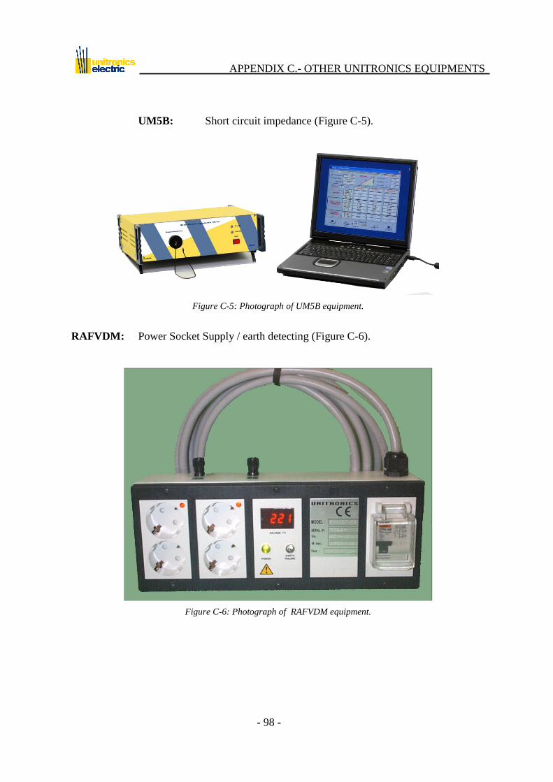
APPENDIX C.- OTHER UNITRONICS EQUIPMENTS
- 98 -
UM5B: Short circuit impedance (Figure C-5).
Figure C-5: Photograph of UM5B equipment.
RAFVDM: Power Socket Supply / earth detecting (Figure C-6).
Figure C-6: Photograph of RAFVDM equipment.
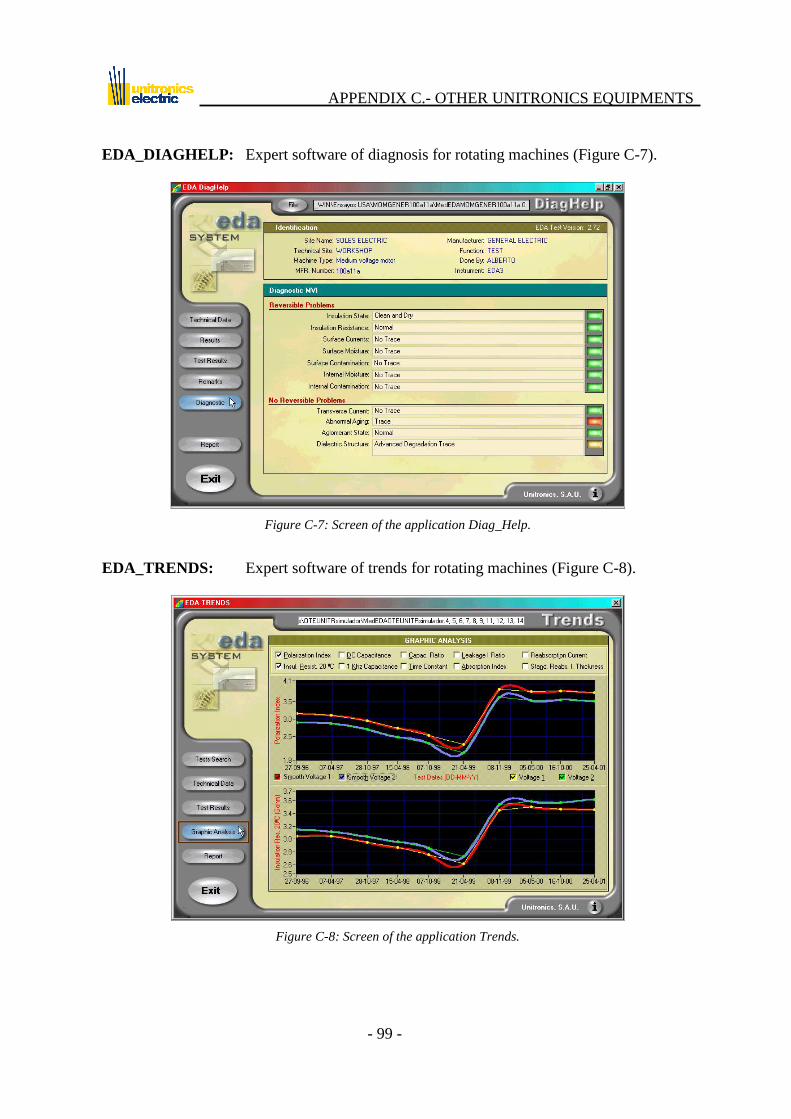
APPENDIX C.- OTHER UNITRONICS EQUIPMENTS
- 99 -
EDA_DIAGHELP: Expert software of diagnosis for rotating machines (Figure C-7).
Figure C-7: Screen of the application Diag_Help.
EDA_TRENDS: Expert software of trends for rotating machines (Figure C-8).
Figure C-8: Screen of the application Trends.
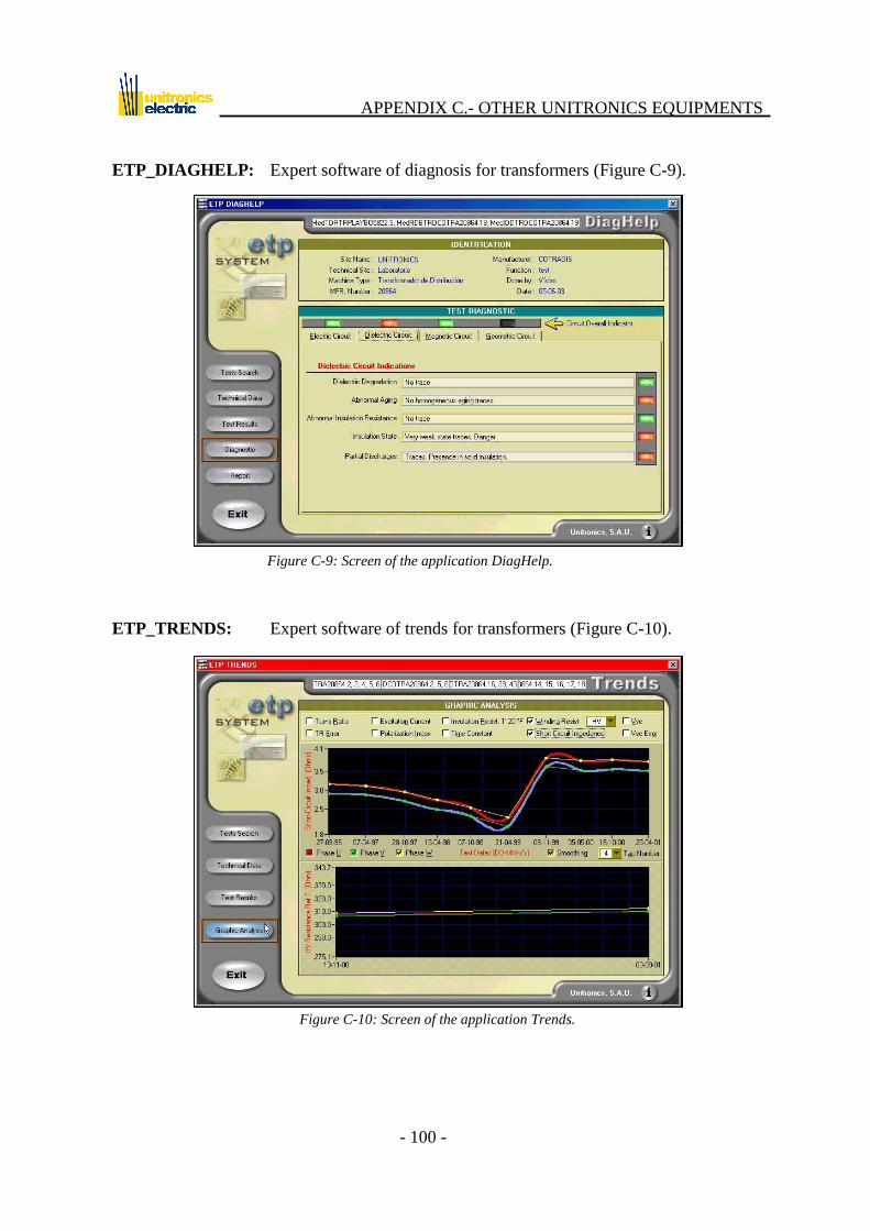
APPENDIX C.- OTHER UNITRONICS EQUIPMENTS
- 100 -
ETP_DIAGHELP: Expert software of diagnosis for transformers (Figure C-9).
Figure C-9: Screen of the application DiagHelp.
ETP_TRENDS: Expert software of trends for transformers (Figure C-10).
Figure C-10: Screen of the application Trends.

APPENDIX D.- GLOSSARY
- 101 -
APPENDIX D.- GLOSSARY
A series of terms habitually used with the equipment are listed below, along with a
description of their function in this area of work.
Adjuster
Device capable of modifying the number of turns of a transformer, and therefore of
changing its transformation ratio. The difference between this and a regulator is that
it is normally fixed at a given position during manufacturing.
Admissible State
Admissible condition of an item for a specific use. This may never be lower than the
condition required for such use by the official and technical regulations. Equivalent
to the term Permissible condition.
Agglutinant:
Substance that allows to fix a dielectric in a surface.
Alternator
Set of apparatus combined to transform kinetic energy into alternating current.
Assembly
Functional unit forming part of an item and made up in turn of components (motor,
turbine).
Autotransformer
Device capable of changing the level of magnitude between input and output, similar
to a transformer, but with the difference that it consists of a single coil with an
intermediate tap, as a result of which there is a common part between the coils.
Availability
Capacity of an item to perform its function at a given moment or over a given period
of time, under defined conditions and at a defined level of performance.
Breakdown
Disappearance of the capacity of an item to perform its specific function. Equivalent
to the term failure.
Bridge
Resistance of low value used to form short-circuits.

APPENDIX D.- GLOSSARY
- 102 -
Bushing
Conducting element aimed at connecting a winding to external conductors.
Capacity
Physical property that allows for the storage of electrical charges between two
insulated conductors (separated by a dielectric) subjected to different potential.
Chassis
Set of elements forming the physical support for a system or item of equipment.
Cleaning
Removal or reduction of dirt, slag, waste material, rust or incrustations in order for an
item to work under better conditions of use.
Coil
Conducting assembly in charge of inductive magnetic coupling.
Component
Unit belonging to an assembly, that is not generally functional by itself, and is
formed by parts (turbine rotor, bearing, cylinder of an engine).
Conductor
Material that allows an electrical current to pass continuously when subjected to a
difference in potential.
Corrosion
Destruction of a material, usually a metal, or of its properties, as a result of reaction
with a medium.
Corrective Maintenance
Maintenance carried out on an item once a breakdown has occurred, returning it to its
Admissible Condition for use. Corrective maintenance may or may not be scheduled.
Current
Movement of electrons between two points of a conductor due to the difference in
potential between both.
Delta connection (D connection)
Connection in series of the phase windings of a three-phase transformer, or of each
winding of the same voltage assigned to single phase transformers constituting a
three-phase bank, performed such that a closed circuit is formed.
Defect
Alteration of the conditions of an item of sufficient importance to cause its normal, or
reasonably foreseeable, function to become unsatisfactory.

APPENDIX D.- GLOSSARY
- 103 -
Diagnosis
Deduction of the nature of a failure based on the symptoms detected.
Dielectric absorption.
The property of dielectrics to regain some charge following the removal of
momentary short-circuits. The dielectric acts as though throughout the charging
period it had become impregnated with a charge that remains during and after the
discharging period. This charge emanates again from the dielectric, causing a
voltage to reappear.
The explanation of this is due to the movement of dipoles and mobile ions in a
dielectric material exposed to an electrical field. It is a measure of the quantity of
impurities present inside the dielectric.
Dielectric rigidity or breakdown potential
Measurement of the resistance of a dielectric to dielectric rupture under the influence
of strong electrical fields, normally expressed in volts per centimeter.
Equipment
Complex unit of higher order made up of assemblies, components and parts, grouped
to form a functional system. Equivalent to the term machine.
Emergency Maintenance
Corrective maintenance required to avoid serious consequences.
Failure
Loss of the capacity of an item to perform its specific function. Equivalent to the
term breakdown.
Fuse
Device protecting apparatus against overload and short-circuit conditions. It contains
a small cross-section conductor that melts when subjected to an excessively intense
current.
Ground
Point of zero potential. Not to be confused with mass.
History file
Record of events, breakdowns, repairs and actuations in general concerning a given
item.
Installation
System made up of items that form a functional production or service unit.

APPENDIX D.- GLOSSARY
- 104 -
Insulation
Substance of low electrical conductivity that contains few free charges capable of
withstanding the influence of an electrical field. The flow of current through such
substances may be considered insignificant.
Insulation resistance
Resistance of an insulating material to the passage of a current, measured in the
direction in which the insulation is to be ensured.
Item
System, sub-system, installation, plant, machine, equipment, structure, building,
assembly, component or part that may be considered individually and that allows for
separate revision or testing.
LED
Abbreviation of Light Emitting Diode. This is a diode that emits light of a certain
wavelength when polarized.
Machine
Complex unit of higher order made up of assemblies, components and parts, grouped
to form a functional system. Equivalent to the term equipment.
Magnetic package
All the elements that make up the electromagnetic coupler that transforms electrical
energy into magnetic energy, for this in turn to be transformed into mechanical
energy (rotating machines) or once again into electricity (transformers).
Maintenance
Set of technical and administrative activities aimed at conserving or replacing an item
in/to conditions allowing it to perform its function.
Maintenance Policy
Strategy governing the decisions of the management of a maintenance organization.
Mass
Point of reference in an electrical circuit.
Modification
Partial change of the design of an item.
Neutral
Point of a symmetrical system of voltages where the potential is normally zero.

APPENDIX D.- GLOSSARY
- 105 -
Non-destructive test
Test performed on a machine applying a voltage lower than the manufacturer‟s
recommended maximum.
Part
Parts making up a component (gaskets, bolts).
Permissible condition
The admissible state of an item for a specific use. This may never be below that
required by the official and technical regulations for each such use. Equivalent to the
term Admissible State.
Phase
Each of the single phase currents that make up a multiple phase system. This term
usually includes the conductors, windings, etc.
Phase winding
Set of spirals forming a multiple phase winding.
Power
Product of the voltage applied to a circuit by the current circulating in it. This is
measured in watts (W).
Predictive Maintenance
Preventive maintenance based on knowledge of the status of an item through the
periodic or continuous measurement of a significant parameter. The intervention of
Maintenance is conditioned to the prompt detection of symptoms of failure.
Preventive Maintenance
Maintenance consisting of performing certain repairs or changes to components or
parts, on the basis of previously established time intervals or certain criteria, to
reduce the probability of failure or loss of performance of an item. This is always
scheduled.
Rack
Frame supporting electronic equipment.
Recovery voltage.
It is the voltage that appears on the terminals of a dielectric previous charged, and it
was applied a short circuit in it for a determined time.

APPENDIX D.- GLOSSARY
- 106 -
Report
Documentation resulting from the performance of a test.
Resistance
Opposition of a conductor to the flow of current.
Regulator
Device capable of modifying the number of turns of a transformer, and thus capable
of changing its transformation ratio.
RPM
Revolutions Per Minute. This indicates the working regime of a machine.
Rotating machine
Set of apparatus combined to receive a certain form of energy and replace it with
another more adequate to produce a certain effect. One of these forms would be
kinetic energy. There are, therefore, generators and AC and DC motors and rotating
converters.
Rotor
Rotating part of a machine.
Rupture
Breakdown causing the unavailability of an item.
Scheduled Maintenance
Preventive maintenance performed at previously determined intervals of time,
number of operations, stroke, etc.
Short-circuit
The joining of two points subjected to different voltages across a very small
resistance (bridge). The current reaches its maximum value.
Short-circuit voltage
This is the voltage that needs to be applied to the high voltage winding in order for
the nominal current to flow through the low voltage winding when the latter is short-
circuited.
Spare
Part, component, assembly, equipment or machine belonging to an item of higher
order and capable of being replaced due to breakage, wear or consumption.
Stator
Fixed part of a rotating electrical machine, in which the rotor turns.
APPENDIX D.- GLOSSARY
- 107 -
Test
Essay performed on an item to assess one of its characteristics.
Transformation ratio
Ratio of the number of spirals in a secondary coil to that of a primary. In practice,
this is the ratio between the voltage in the high voltage winding and that of the low
voltage/tertiary winding.
Transformer
Device capable of changing the level of magnitude between input and output,
providing galvanic insulation between them.
Turn
Spiral of a conducting wire around a magnetic nucleus.
Voltage
Difference in potential between two points. Measured in volts (V).
Winding
Set of spirals forming an electrical circuit associated with one of the voltages for
which the transformer has been designed. Current conducting part of a machine.
Wye connection (Y connection)
Connection of windings in which the end of each phase winding of a three-phase
transformer, or of each winding of the same voltage assigned to single phase
transformers constituting a three-phase bank, is connected to a common point
(neutral), the other end being connected to the terminal of the corresponding line.
Zig-zag connection (Z connection)
Connection of windings such that one end of each phase winding of a three-phase
transformer is connected to a common point (neutral) and where each phase winding
has two parts into which out-of-phase voltages are induced.