Embed Size (px)
Citation preview

This content has been downloaded from IOPscience. Please scroll down to see the full text.
Download details:
IP Address: 131.113.58.246
This content was downloaded on 26/06/2015 at 09:02
Please note that terms and conditions apply.
Recovery of microstructure and surface topography of grinding-damaged silicon wafers by
nanosecond-pulsed laser irradiation
View the table of contents for this issue, or go to the journal homepage for more
2009 Semicond. Sci. Technol. 24 105018
(http://iopscience.iop.org/0268-1242/24/10/105018)
Home Search Collections Journals About Contact us My IOPscience

IOP PUBLISHING SEMICONDUCTOR SCIENCE AND TECHNOLOGY
Semicond. Sci. Technol. 24 (2009) 105018 (6pp) doi:10.1088/0268-1242/24/10/105018
Recovery of microstructure and surfacetopography of grinding-damaged siliconwafers by nanosecond-pulsed laserirradiation
Jiwang Yan1,3, Shin Sakai2, Hiromichi Isogai2 and Koji Izunome2
1 Department of Nanomechanics, Graduate School of Engineering, Tohoku University,Aramaki Aoba 6-6-01, Aoba-ku, Sendai 980-8579, Japan2 Covalent Materials Corporation, 6-861-5 Higashiku, Seirou-machi, Kitakanbara-gun,Niigata 957-0197, Japan
E-mail: [email protected]
Received 19 May 2009, in final form 29 July 2009Published 18 September 2009Online at stacks.iop.org/SST/24/105018
Abstract
Single crystalline silicon wafers whose surfaces were machined by diamond grinding wereirradiated by a nanosecond-pulsed Nd:YAG laser. Changes in the subsurface crystallinity andsurface topography were investigated by transmission electron microscopy and atomic forcemicroscopy. It was found that the grinding process gave rise to amorphous layers, dislocationsand micro cracks. However, all of this damage could be eliminated by a single laser pulse ofsuitable energy density, which also led to a remarkable amount of smoothing of the wafersurface. When excessively high energy densities were used, tiny particles were found to formon the wafer surface. It is speculated that these particles are produced by the recondensation ofsilicon boiled away from the wafer surface during the laser pulse. The temperature rise duringlaser irradiation was estimated using a simplified model. The results obtained in this studysuggest that nanosecond-pulsed laser irradiation may be an effective approach for processinggrinding-damaged silicon wafers.
(Some figures in this article are in colour only in the electronic version)
1. Introduction
Silicon wafers used for the fabrication of ultra-large-scaleintegration (ULSI) devices are usually manufactured bymechanical and chemical processes such as slicing, lapping,grinding, etching and polishing. The mechanical processesinevitably cause subsurface damage, such as microstructuralchanges and the introduction of dislocations, to the siliconsubstrates [1–5], and removal of this damage is essential forproducing reliable devices. In conventional rough grindingprocesses, micro cracks generated beneath the wafer surfacemay extend to a depth of ∼10 μm, or much deeper. Tocompletely remove such a thick subsurface damage layer,chemical etching and chemo-mechanical polishing (CMP)
3 Author to whom any correspondence should be addressed.
processes are necessary. In recent years, however, theductile mode grinding (DMG) technique has been developedand widely used for precision machining of silicon wafers[6, 7]. In DMG, by using ultraprecision grinding machinesand grinding wheels with extremely fine diamond abrasives,no micro cracks will be generated in the wafers. In thiscase, the grinding-induced subsurface damage layer will beextremely thin, consisting of an amorphous layer (depth ∼ afew tens of nanometers) and dislocations (depth ∼ a fewhundreds of nanometers). To further improve the quality ofsuch precision-machined silicon wafers in place of etching andchemo-mechanical polishing, an alternative method currentlybeing considered is the use of laser irradiation. In a previouspaper [8], Yan et al demonstrated the feasibility of recoveringthe lattice structure of diamond-cut silicon wafers by using ananosecond-pulsed Nd:YAG laser. The subsurface structure
0268-1242/09/105018+06$30.00 1 © 2009 IOP Publishing Ltd Printed in the UK

Semicond. Sci. Technol. 24 (2009) 105018 J Yan et al
recovery mechanism involved the sudden melting of thedamaged layer and the subsequent epitaxial regrowth fromthe damage-free bulk during cooling [8]. In comparison withchemo-mechanical or chemical processes, laser irradiationoffers a number of advantages: (i) it involves no removal ofmaterial, thus preserving the dimensions of the workpiece;(ii) it generates no pollutants; (iii) it enables selectiveprocessing and processing of complex shapes.
In this paper, silicon wafers machined by ultraprecisiondiamond grinding were used as specimens for laser irradiationtests. Such grinding is a very important technical step in thecurrent silicon wafer manufacturing process [9]. In contrast tosingle-point diamond cutting, the grinding process gives riseto non-uniform subsurface damage layers with complicatedmicrostructures. In addition, significant grinding marks andsurface waviness may be produced. Therefore, two effects areexpected during laser processing of ground wafers: one is animprovement in the subsurface integrity, and the other is thesmoothing of the grinding marks. In this paper, the responseof precisely diamond-ground silicon wafers to a nanosecond-pulsed Nd:YAG laser was experimentally investigated. Theeffects of laser energy density on the changes in the subsurfacestructure and surface topography of the wafers were examined.
2. Experimental procedures
Boron-doped p-type device-grade single-crystal silicon (1 0 0)wafers machined by diamond grinding were used as specimensin this study. The grinding procedure was carried out with anultraprecision grinder equipped with vitrified grinding wheelswith fine diamond abrasives. The average size of the abrasivegrains was approximately 2 μm.
The machined sample was then irradiated by a Nd:YAGlaser machining system, QuikLaze-50, produced by New WaveResearch, Inc. (Fremont, USA). This system employs a flashlamp pumped Nd:YAG rod in a thermally compensated threebar invar resonator to generate radiation at 1064 nm. The1064 nm laser pulse was passed through an angle-tuned KTPcrystal to generate a second harmonic at 532 nm. The laserbeam was shaped to a rectangle using XY apertures, and afterpassing through an objective lens a maximum beam width of50 × 50 μm2 was obtained. In the present experiment, theXY apertures were both set to 40%, producing a 20 × 20 μm2
square irradiation area. A single pulse mode was used and thepulse width was 3–4 ns. The incident energy of each laserpulse was varied from 0.96 to 5.76 μJ, leading to a change inenergy intensity from 0.24 to 1.44 J cm−2. The laser irradiationconditions are summarized in table 1.
To investigate the changes in the subsurfacemicrostructure resulting from laser irradiation, cross-sectional observations of the sample were performed usingtransmission electron microscopy (TEM). The instrumentused was an H-9000UHRIII, produced by Hitachi Ltd (Tokyo,Japan). The acceleration voltage was 300 kV. To preparethe TEM samples, the silicon wafers were processed by ionmilling using a Dual Mill 600 system (Gatan, Inc., USA).To protect the sample from possible damage during ionmilling, a carbon coating was deposited on the surface.
Table 1. Laser irradiation conditions.
Laser type Nd:YAG
Wavelength 532 nmPulse width 3–4 nsPulse mode Single pulseIrradiation area 20 × 20 μm2
Energy density 0.24–1.44 J cm−2
Environment In air
To determine surface topographical changes, the samplesurface was characterized using an atomic force microscope(AFM) Nanoscope IIIa (Veeco Instruments, USA). The AFMmeasurements were performed within a 10 × 10 μm2 squarearea under a tapping mode. Five samples were made foreach laser irradiation condition, and two of them were takenfor TEM observation. Surface roughness measurement wasperformed for all the samples.
3. Results
3.1. Subsurface structural changes
Figure 1(a) shows a cross-sectional TEM micrograph of asilicon wafer, where the left side is a region without laserirradiation and the right side was irradiated at a low energydensity of 0.72 J cm−2. Figures 1(b) and (c) are close-up viewsof the unirradiated and the irradiated region, respectively, asindicated in figure 1(a). From figure 1(b), it can be seenthat severe subsurface damage has resulted from the grindingprocess, leading to the formation of both an amorphous layerand a dislocated layer. In contrast to diamond-cut samples[5, 8] where the subsurface damage depth was uniform, thedepths of both the amorphous layer and the dislocation layerin figure 1(b) vary greatly from place to place. The totalthickness of the damage layer ranges from approximately50 nm to 150 nm. From figures 1(a) and (b), it can be seen thatbefore laser irradiation the surface unevenness correspondingto the grinding marks is approximately 40 nm, which is muchrougher than that of the diamond-cut surface [5, 8]. After laserirradiation (figure 1(c)), the amorphous layer has disappearedand the surface unevenness has been reduced slightly. Inaddition, the number of dislocations has decreased distinctlyand a few regions have become damage-free. Therefore, it canbe said that under this laser irradiation condition, grinding-induced subsurface damage has been partially removed.
Figure 2(a) shows a cross-sectional TEM micrograph ofa sample where the left side was unirradiated and the rightside was irradiated at a high energy density of 1.44 J cm−2.Figures 2(b) and (c) are high-magnification images of the tworegions indicated in figure 1(a). As before, the subsurfacedamage in the unirradiated region includes an amorphouslayer and a dislocated layer. Also, several sharp protrusionsof dislocations into the substrate could be observed, whichare presumably potential micro cracks. However, after laserirradiation, all grinding damage including the amorphouslayer, the dislocations and the micro cracks, have disappearedcompletely, and the near-surface layer has the same structureas the bulk region. From figure 2(c), it is also evident that
2

Semicond. Sci. Technol. 24 (2009) 105018 J Yan et al
(a)
(b)
(c)
200 nm
Unirradiated region Boundary Irradiated region
(b) (c)
40 nm
Amorphous layer
Dislocations
40 nm
Damage-free region
Residual dislocations
Figure 1. Cross-sectional TEM micrographs of a silicon wafer:(a) a general view showing the unirradiated region on the left sideand the laser irradiated region on the right side. The laser energydensity was 0.72 J cm−2; (b) and (c) are close-up views of theregions indicated by the white lines in (a).
after laser irradiation the wafer surface has become distinctlysmoother than that of the unirradiated region (figure 2(b))and that of the specimen irradiated at the low energy density(figure 1(c)).
3.2. Surface topographical changes
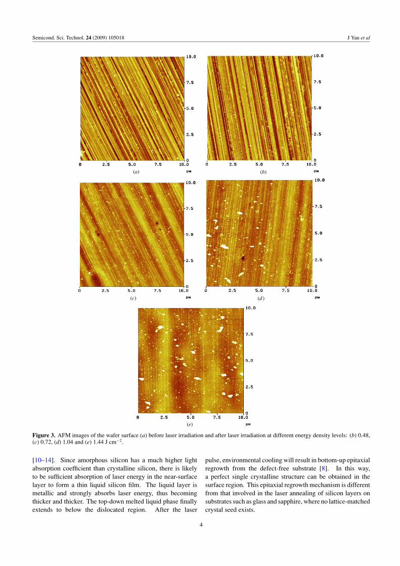
Next, the changes in surface topography were investigatedusing AFM. Figures 3(a)–(e) show AFM images of the wafersurface before and after laser irradiation at different energydensities. As shown in figure 3(a), before laser irradiationnumerous parallel grinding marks, a few tens of nanometersin height and several hundreds of nanometers in width, areclearly seen on the surface. These are obviously the result ofthe single-point cutting and scratching effects of the diamondabrasive grains. After laser irradiation at an energy density of0.48 J cm−2, no obvious change in surface topography couldbe detected, as shown in figure 3(b). However, at a higherenergy density of 0.72 J cm−2, a few fine grinding marksdisappeared and the surface became significantly flatter, asshown in figure 3(c). When the energy density was furtherincreased to 1.04 J cm−2 (figure 3(d)), a further large increasein surface smoothness occurred, while a few sub-micron-sized particles began to appear on the surface. Figure 3(e)shows the result obtained at an energy density of 1.44 J cm−2,
(a)
(b)
(c)
(b) (c)
Figure 2. Cross-sectional TEM micrographs of a silicon wafer:(a) a general view showing the unirradiated region on the left sideand the laser irradiated region on the right side. The laser energydensity was 1.44 J cm−2; (b) and (c) are close-up views of theregions indicated by the white lines in (a).
where it can be seen that both the number and the size ofthe small particles have increased slightly in comparison withfigure 3(d).
Figure 4 shows a plot of surface roughness against laserenergy density. The surface roughness was calculated asthe root mean square (RMS) value of the three-dimensionalAFM topography data. The surface roughness before laserirradiation was ∼12 nm. At a laser energy density of0.72 J cm−2, it shows a sudden decrease to ∼8 nm. However, itbegan to increase again from an energy density of 1.04 J cm−2.This increase at higher energy densities was found to be dueto the presence of the small particles. After recalculationfollowing removal of the data points corresponding to thebiggest twenty particles, the surface roughness became similarto or smaller than that obtained at an energy density of0.72 J cm−2, as indicated by triangles in figure 4.
4. Discussion
The mechanism of surface topographical and subsurfacemicrostructural changes during laser irradiation has notyet been completely clarified. It is presumed that therecovery of the subsurface structure may be the result ofsudden melting of the surface layer and subsequent epitaxialregrowth during cooling [8]. A similar phenomenon hasbeen confirmed in conventional laser annealing processes
3
Semicond. Sci. Technol. 24 (2009) 105018 J Yan et al
(a) (b)
(c) (d )
(e)
Figure 3. AFM images of the wafer surface (a) before laser irradiation and after laser irradiation at different energy density levels: (b) 0.48,(c) 0.72, (d) 1.04 and (e) 1.44 J cm−2.
[10–14]. Since amorphous silicon has a much higher lightabsorption coefficient than crystalline silicon, there is likelyto be sufficient absorption of laser energy in the near-surfacelayer to form a thin liquid silicon film. The liquid layer ismetallic and strongly absorbs laser energy, thus becomingthicker and thicker. The top-down melted liquid phase finallyextends to below the dislocated region. After the laser
pulse, environmental cooling will result in bottom-up epitaxialregrowth from the defect-free substrate [8]. In this way,a perfect single crystalline structure can be obtained in thesurface region. This epitaxial regrowth mechanism is differentfrom that involved in the laser annealing of silicon layers onsubstrates such as glass and sapphire, where no lattice-matchedcrystal seed exists.
4

Semicond. Sci. Technol. 24 (2009) 105018 J Yan et al
0
2
4
6
8
10
12
14
16
18
0.0 0.2 0.4 0.6 0.8 1.0 1.2 1.4 1.6
Su
rface r
ou
gh
ness n
m R
MS
Energy density (J/cm2)
Figure 4. Plot of surface roughness (RMS) versus laser energydensity.
Heat conduction
Heat radiation
Heat convection
1 m
20 m
20 m
Laser irradiation
Unabsorbed laser
Figure 5. Simplified model for calculating the temperature rise dueto laser irradiation.
The melting of silicon has been confirmed in theconventional laser annealing process by measuring the time-resolved optical reflectivity [13] or by detecting thepresence/absence of oxygen thermal donors and oxidation-induced stacking faults [14]. In this work, it was difficult forthe authors to directly detect the melting phenomenon. Instead,we made a rough estimation of laser-induced temperature riseusing a simplified model shown in figure 5, since the meltingof silicon depends on the surface temperature rise. It is firstsupposed that a fraction of the energy of the laser beam willbe uniformly absorbed by a small volume of material withdimensions 20 × 20 × 1 μm3 on the wafer surface (20 ×20 μm2 is the area of the laser irradiated region, and 1 μm isthe penetration depth of the 532 nm Nd:YAG laser into silicon[15]). Then, the temperature rise (�T) in this small volumecan be described by the following equation:
�T = Q · η
c · M= E · S · η
c · M, (1)
where Q is the total quantity of heat generated by the laserirradiation, η is the energy absorption ratio of the volumetaking into account the heat lost by conduction, radiationand convection, E is the energy density of the laser, S isthe area of the irradiated region, c is the specific heat ofsilicon and M is the mass of the material within the smallvolume. In this paper, these parameters were assigned thefollowing values: E = 0–1.60 J cm−2, S = 4.0 × 10⁻⁶ cm2,c = 680.4 J ◦C−1 kg−1, M = 9.32 × 10⁻¹³ kg. A rough
0
1000
2000
3000
4000
5000
6000
0.0 0.2 0.4 0.6 0.8 1.0 1.2 1.4 1.6
Tem
pera
ture
ris
e
()
Energy density E (J/cm2)
Boiling point2878°C)
Melting point (1412°C)
Figure 6. Plot of the calculated temperature rises against energydensity.
approximation of η ≈ 0.5 was made by considering the laserabsorption coefficients of single crystalline and amorphoussilicon, respectively, and the heat loss due to conduction,radiation and convection. A detailed analysis of laserabsorption and heat transfer will be presented in a future paper.
The calculated temperature rise as a function of energydensity is plotted in figure 6. It can be seen that at an energydensity of 0.48 J cm−2, the temperature rise is 1514 ◦C, whichis higher than the melting point of silicon (1412 ◦C). This resultgenerally agrees with the experimental result that the surfaceroughness of the wafer decreased after laser irradiation at anenergy density level higher than 0.48 J cm−2. This fact, tosome extent, demonstrated the validity of the estimation modelwe used. In figure 6, when the energy density is increased to0.96 J cm−2, the temperature rise becomes 3028 ◦C, whichis higher than the boiling point of silicon (2878 ◦C) [16].From this result, it is suggested that if the laser energy densityis sufficiently high, silicon on the surface can boil and bescattered as small droplets. These droplets, after the laser pulsehas terminated, would be reattached to the surface forming tinyparticles. These surface particles can be completely removedby slightly performing polishing after laser irradiation.
It should be pointed out that parameters used in theanalysis, such as the energy absorption ratio, may not bequantitatively accurate. Also, an assumption was made thatenergy absorption was uniform within the small volume, andthis may not be the case in reality. Therefore, the results of thecalculations presented here must be considered as a startingpoint only. Further work is necessary to improve the model andits parameters. Also, further experiments are needed to findthe optimum laser irradiation conditions to cause the siliconsurface to melt without boiling, so that the damage layer can berecovered without the formation of unwanted particles. In thatcase, the laser processed wafer surface will be as smooth as thepolished one, and there will be no need for further polishing.
An important finding from the present study is the abilityof laser irradiation to smooth the silicon surface. The drivingforce for the smoothing effect might be the surface tension ofthe melted silicon thin film. Similar to the manner in whicha free droplet of liquid naturally assumes a spherical shapeto achieve a minimum surface area to volume ratio, in thisstudy the surface area reaches a minimum when the silicon
5

Semicond. Sci. Technol. 24 (2009) 105018 J Yan et al
liquid becomes completely flat. Since the proposed techniqueoffers the combined advantages of damage removal and surfacesmoothing, it has considerable potential as a single step processto improve the near-surface quality of silicon wafers.
5. Conclusions
Diamond-ground silicon wafers were irradiated by ananosecond-pulsed laser and changes in the subsurfacestructure and surface topography were investigated. The mainconclusions can be summarized as follows.
(1) The grinding process was found to give rise to anamorphous layer on the silicon surface in addition todislocations and potential micro cracks. The totalthickness of the subsurface damage layer varied fromapproximately 50 nm to 150 nm.
(2) Following a single laser pulse at a sufficiently highenergy density (∼1.44 J cm−2), subsurface defects werecompletely eliminated and a single-crystal structure wasrecovered.
(3) Grinding marks were smoothed significantly after laserirradiation, leading to a decrease in RMS surfaceroughness from ∼12 to ∼8 nm.
(4) At high energy densities (>1.04 J cm−2), small particleswere formed on the wafer surface. It is speculated thatthese are generated by the boiling and scattering of liquidsilicon droplets.
Acknowledgment
This work has been supported in part by a grant-in-aid forExploratory Research (project no 20656023) from the JapanSociety for the Promotion of Science (JSPS).
References
[1] Shibata T, Ono A, Kurihara K, Makino E and Ikeda M 1994Appl. Phys. Lett. 65 2553–5
[2] Puttick K E, Whitmore L C, Chao C L and Gee A E 1994 Phil.Mag. A 69 91–103
[3] Gogotsi Y, Baek C and Kirscht F 1999 Semicond. Sci. Technol.14 936–44
[4] Yan J 2004 J. Appl. Phys. 95 2094–101[5] Yan J, Asami T and Kuriyagawa T 2007 Precis. Eng.
32 186–95[6] Noboru M 2000 Microscopic mechanism of ductile mode
grinding of silicon wafer J. Japan. Soc. Abrasive Technol.44 426–8
[7] Klocke F and Pahler D 2001 Precision machining of futuresilicon wafers Initiatives of Precision Engineering at theBeginning of a Millennium Proc. of the 10th InternationalConf. on Precision Engineering (ICPE) (Yokohama, Japan,18–20 July 2001) (Berlin: Springer) pp 411–5
[8] Yan J, Asami T and Kuriyagawa T 2007 Semicond. Sci.Technol. 22 392–5
[9] Pei Z J, Li Z C and Fisher G R 2007 Grinding of silicon wafersin the nanotechnology era Semiconductor Machining at theMicro–Nano Scale ed J Yan and J Patten (Kerala, India:Transworld Research Network) pp 219–41
[10] Bean J C, Leamy H J, Poate J M, Rozgonyi G A, Sheng T T,Williams J S and Celler G K 1978 Appl. Phys. Lett.33 227
[11] Venkatesan T N C, Golovchenko J A, Poate J M, Cowan Pand Celler G K 1978 Appl. Phys. Lett. 33 429
[12] Murakami K, Gamo K, Namba S, Kawabe M and Aoyagi Y1979 Appl. Phys. Lett. 35 628
[13] Luthy W, Affolter K, Weber H P, Roulet M E, Fallavier M,Thomas J P and Mackowski J 1979 Appl. Phys. Lett.35 873
[14] Hayafuji Y, Aoki Y and Usui S 1983 Appl. Phys. Lett. 42 720[15] Neuberger M and Wells S J 1969 Silicon Data sheet DS-162
p 110[16] Yaws C L, Lutwack R, Dickens L L and Hsu G 1981 Solid
State Technol. 24 87–92
6