Embed Size (px)
Citation preview
Recovery and Treatment of
The discharge of oil or fats into water courses has come under careful scrutiny in recent years. As a result of various industrial process waste surveys, some con- ducted by the Ministry of the Environment, The Steel Company of Canada embodied within its negotiated water quality program, the necessary facilities to safe- guard against potential oil contamination of process water. A particularly vexing problem was the waste effluent from the cold rolling mills that contain a com- bination of rolling and lubricating oils.
Rolling solutions are required to permit the cold roll- ing of carbon steel with modern high speed mills. In the formulation of these solutions, various types of tallows and mineral oils are blended to form an oil- water emulsion. These emulsions are tailored for specific applications by adding proprietary stabilizing agents that give the rolling solution specific lubricating and pressure bearing properties. During use these solutions become contaminated with metal soaps and iron fines.
Treatment of the spent solutions is essential before discharging the waste water together with large quanti- ties of cooling water to the industrial sewer. In the late sixties some of the solutions along with hydraulic fluid and equipment lubricating greases were collected in clarifiers at the cold mill basement complex. The fatty oils were allowed to solidify in the clarifiers. The solids were skimmed and collected for disposal. The major portion of the spent water containing some residual oil was then discharged to the industrial sewer and further settled and skimmed in a terminal lagoon system. The method provided partial oil recovery, but the degree of treatment was insufficient to meet the requirements of the water quality control program. Therefore, the avail- able technology for treating waste rolling solutions was studied again. Laboratory results conducted on Stelco's spent solutions revealed that: (a) The oil-water emulsions could be separated with
chemical treatment using ferric iron and pH control.
(b) The chemical requirements to achieve the separation depended on the oil concentration.
(c) Upgrading the existing purification system to ob- tain adequate treatment in terms of flow and water quality would be uneconomical.
In order to achieve adequate effluent treatment, the facility would have to be located in an area remote from the source. This would allow the selection of a system that could handle the waste flows from all the cold rolling mills, as well as waste oily-water solutions generated by other steel finishing operations from The Steel Company of Canada, Limited.
-1 NON-EMULSIFIED . OILS I 1 RE%" FOR CHEMICAL TREATMENT
4 STAND BASEMENT EMULSIFIED HOLDING TANK
PUMP L m E
PUMP
ACID- Iyz: . SCUM PUMP
1 OIL rH*l +FB +Moa 1 0 2 +HEAT(lBOW -Fa01 +Ha r + OIL
Flg I
With this fundamental knowledge, several processes were reviewed, and a patented system was selected. The advantages of selecting this process were: (1) The process was being used by other steel
producers for the purpose of recovering fatty oils that solidified while standing.
(2) Economically, the operating costs were min- imized since part of the chemical treatment sys- tem used a by-product from the oil recovery sys- tem itself.
(3) The process would produce a recovered oil that could be used as fuel and generate a minimal amount of solid waste for disposal.
(4) The technology of chemically treating oil-water emulsions was available and had been used in part, in other steel plants.
Basically the process consists of two separate sys- tems. One stage recovers solidified oils; the other treats the oily water emulsions. The oily water treating system is completely spared to ensure continuous treatment and to permit routine and emergency mainte- nance. The plant has been in operation since April, 1972. The facility has been treating all contaminated process water from various cold rolling operations at Hilton Works. In addition, waste oil products from a number of steel finishing operations are also treated to recover a useful fuel oil. In this sense, the completion of the centralize6 oii recovery system represetits a
PRIMARY OIL RECOVERY
#RON SULFATE STORAQE TANK
I PRIMARY OIL REFlNER
'Presented at the 21st Ontario Industrial Waste Conference June, 1974 Toronto, Ontario, Canada Fig 2
20 INDLISTRIAI WASTFS . I A N I IARVIFFRRI I A R V 107~;

\ b
Spent Steel Mill Solutions *
major effort and partial fulfillment of an extensive water quality control program.
The oi l recovery system is best described with a series of process flow diagrams that cover the two main treatment stages-batch treatment of the solidi- fied oils and the continuous treatment of oil-water emulsions. The continuous treatment stage is a dupli- cated system in which each stage is capable of treating 1,500 U.S. gpm of waste water.
In the batch treatment of solidified oils, the spent process waters containing various rolling solutions are collected from all rolling mills and are piped to the oil recovery plant. The spent water is admitted to one of two 50,000 U.S. gal. surge receivers (Fig. 1). In the surge receivers, the initial oil-water separation occurs, and some solidified oil floats to the surface. The solidi- fied oils or fats are then refined in the batch stage of the plant. The weak solutions of emulsified oil-water mixtures are pumped continuously to the emulsion treatment stage.
The treatment of the solidified scum is as follows. The floating material is pumped to the scum tank by periodically draining one of the surge receivers. The water level is lowered and the scum is heated with steam to liquify the material. The material can then be pumped to the primary oil refiner. The treatment consists of mixing concentrated sulfuric acid with the scum, heating the mixture with steam, and air agitating the batch. The reaction that occurs can be represented in the following manner. -
Heat Oil + water + iron + H2SO4 + air -+ FeSO4 + H2 f + acidicoil 180°F
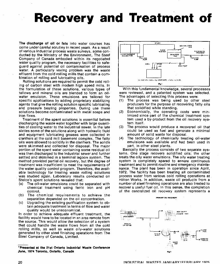
The purpose of the acid treatment is to dissolve the metal soaps. The resultant mixture is allowed to settle and yields two layers (Fig. 2). The aqueous liquid phase containing the iron salt solution is on the bot- tom, and the acidic oil phase is on the top. The iron solution is pumped to a plastic storage tank to be re- cycled cis one of the ciiernicais for treating wastewater. Alternatively, any excess iron sulfate solution can be neutralized with lime and filtered to remove the solids.
The acidic oils are then pumped to a rotary vacuum filter and filtered at a temperature of 180 degrees F. Fil- tration removes inert grit, and the filtering action im- proves the separation of the oil from the water phase. The acidic oil then is water washed at 180 degrees F. to remove the residual acidity. After several hours of standing, the water that has percolated through the oil is decanted. The water can be blended with the concen- trated iron sulfate solution for future use or it can be returned directly to the oil-water treatment system for reprocessing. Clean and relatively dry oil may then be stored or shipped as fuel for internal consumption. The batch operation recovers about 15,000 to 25,000 U.S. gal. of oil per month.
By A.A. Schuldt, and V.A. Suffoletta, The Steel Company of Canada, Ltd. Hilton Works Operation
The second stage deals with the continuous treat- ment of oil-water emulsions and is shown in Fig. 3.
The oily water emulsions are chemically treated by forming a slightly cationic iron hydroxide floc that combines with the remaining oil in the spent rolling solutions. The emulsions in this case are normally slightly anionic. The emulsified oily water, having con- centrations of oil ranging from 100 to 2,000 ppm are automatically withdrawn from the surge receivers at preset rates by the waste injection pumps. These pumps discharge directly into the suction line of the main water pumps that have a common suction con- nection from the injection pumps and from a treated clean water sump tank. The preferential flow will be from the injection pumps. The purpose of the pumping arrangement is to ensure that a constant flow of water is pumped to the clarifier, regardless of the quantity of raw water available for treatment so that fluctuations in flows are stabilized. Furthermore, the technique re- duces the possibility of having to treat highly concen- trated mixtures.
pH Adjustment Initially the plant was operated at a recommended
pH of 7.0, but this resulted in very high soluble iron in the discharge water. Plant stability could not be main- tained, and late floc formation occurred. After running the plant within a pH range from 5 to 11 under con- trolled conditions, the optimum pH was in the range of 8.5 to 10. Chemical Feed System
In operating the water system as described previous- ly in Fig.3, the design specifications were not consis-
(continued on page 22)

tently approached. The plant was designed to meet the following standards:
The typical operating range during a 30 day test period was as follows:
Phase I - Initial Start-up
Suspended solids - less than 15 ppm. Oils - less than 10 ppm.
Maximum Minimum Average PPm PPm PPm
Suspended solids 307 15 111 Carbon tetrachloride 275 8 76 Extractables (oil)
On the basis of these test 'results, an investigation revealed that: (1) The lime was not fully dispersed in the water, hin-
dering the reaction with the dissolved iron. (2) The floc formation was incomplete and, on
occasion, occurred after the air release. The delay resulted in suspended solid carryover.
(3) The fragile iron hydroxide floc was being sheared by the pump impeller.
The chemical injection point for the iron solution was changed to the discharge side of the main water pumps. The change was prompted to overcome ineffi- ciencies in the mixing and to reduce floc degradation.
This adjustment solved the problem of mixing the lime, but the suspended solid carry over did not drop significantly. The iron floc still appeared to be shearing and eventually, the baffles in the pipe reactor were re- duced in size. Furthermore, to ensure sufficient time for the floc to form, a chemical stabilizer tank was added. These additional changes provided greater stability and improved the quality of the effluent. The average plant effluent under these conditions for another 30 day test period was:
Phase 2 - Relocation of Chemical Injection
Maximum Minimum Average PPm PPm PPm
Suspended solids 320 ' 11 80 Carbon tetrachloride 306 2 50 Extractables (oi I)
Additional investigations revealed that the floc could be compacted and stabilized through the addition of polyelectrolytes (Fig. 5). The polymer was ultimately added at the discharge pipe of the chemical stabilizer
tank with a dosage of one ppm. The effluent was sampled for 28 days. During this period, the plant ran 50 per cent of the time under 15 m g l l suspended solids and ten ppm oil. The average for the entire per- iod was 16.6 m g l l suspended solids. The performance on the basis of residual oils was satisfactory.
Internal System Upsets On examination, certain regular upsets appeared to
occur whenever neutralized iron solut ions were filtered. The material was being filtered on a belt filter (Fig. 6). As the drum rotated and vacuum was applied, the solid built up on the filter cloth. The cloth that held the solid moved around a set of deflector rolls, causing the solids to fall off. Water sprays then washed the cloth. The dirty water was reprocessed by pumping the solution to the surge receivers. The solution consis- tently had a high suspended solid loading, with values as high as 100,000 m g l l suspended solids.
The reintroduction of dirty water with its fluctuating solid level caused chemical imbalances and resulted in uncontrollable plant conditions. The upsets made the plant operation very difficult. Visually, the nature of the floc was changed, and it was difficult to remove the fine floc with surface skimmer paddles. A precoat filter is now being used. The modification has reduced the uncontrolled recycled load of iron and solids to the system, and the consistency and quality of the floc has improved. The solid load returned to the system is in the range of 5 to 60 m g l l suspended solids.
At this juncture, chemicals are added to break the oil-water emulsion. A 0.5 percent iron sulfate solution is injected into the suction of the main water pumps. Lime is added to control the pH of the mixture, and the total blend is pumped to the trombone reactor. The following reactions take place.
Fe (304j3 + 32aiOHj2 + Fe6Od + Ca(OH)2 +
2 Fe(GHjg + 3 CaSD4 Fe(OH)2 + Cas04
As soon as the chemicals come together, an iron -
hydroxide floc is formed and is further developed in the trombone reactor. The finely dispersed floc entraps the oil particles. Also at this point, sufficient air is added for complete air dissolving and to foster the oxidation of the iron floc.
2 Fe(OH)2 + 1h02 + H20 +
~
2 Fe(OH)3 The addition rates of chemicals are automatically con- trolled on the basis of flow and of the pH of the water.
The reacted water mixture (Fig. 3) i s piped under pressure to a skimming vessel with a capacity of 50,000 U.S. gal. As the water enters the skimmer, the pressure is released. The dissolved air evolves from the solution
1 h 1 n~ ~ m T n l n I I n I A PTCP I A h l I I A DV I CCDD1 I A D V 4 n 7 C
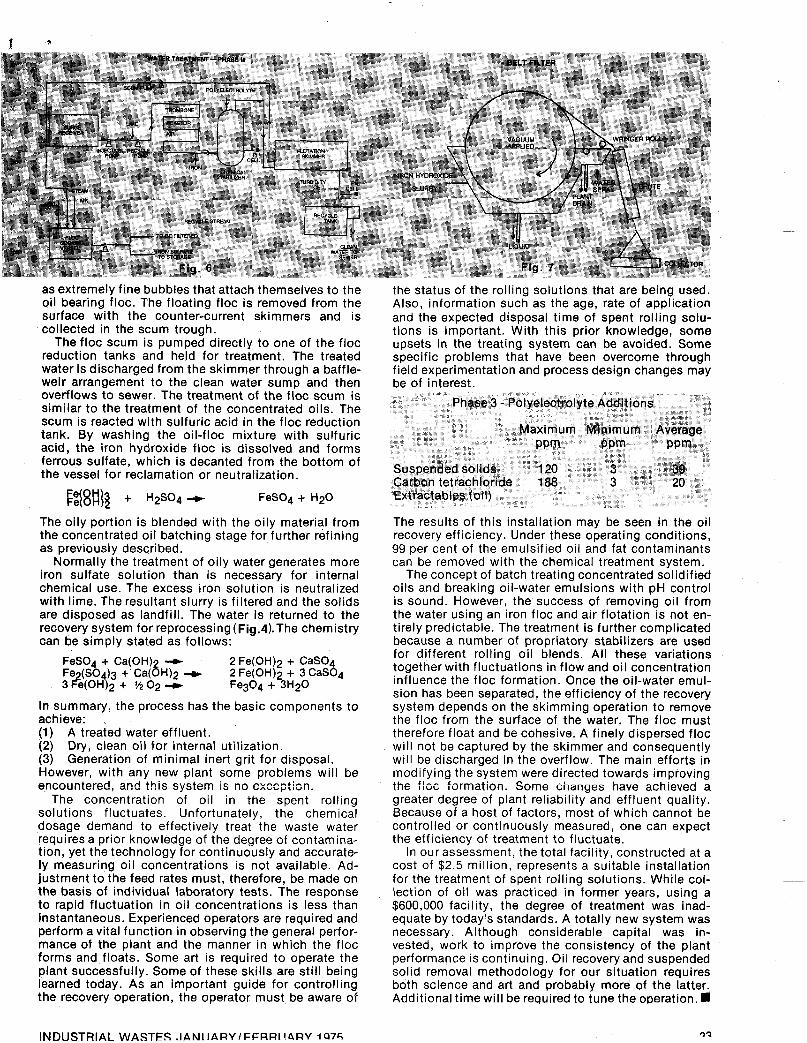
as extremely fine bubbles that attach themselves to the oil bearing floc. The floating floc is removed from the surface with the counter-current skimmers and is collected in the scum trough.
The floc scum is pumped directly to one of the floc reduction tanks and held for treatment. The treated water is discharged from the skimmer through a baffle- weir arrangement to the clean water sump and then overflows to sewer. The treatment of the floc scum is similar to the treatment of the concentrated oils. The scum is reacted with sulfuric acid in the floc reduction tank. By washing the oil-floc mixture with sulfuric acid, the iron hydroxide floc is dissolved and forms ferrous sulfate, which is decanted from the bottom of the vessel for reclamation or neutralization.
FeS04 + H20
The oily portion is blended with the oily material from the concentrated oil batching stage for further refining as previously described.
Normally the treatment of oily water generates more iron sulfate solution than is necessary for internal chemical use. The excess iron solution is neutralized with lime. The resultant slurry is filtered and the solids are disposed as landfill. The water is returned to the recovery system for reprocessing (Fig.rl).The chemistry can be simply stated as follows:
FeS04 + Ca(0H) -+ 2 Fe(OH)2 + Cas04 Fe (SO )3 + Ca(8H)2 --(c
3 3e(OH42 + vi 0 2 -+ 2 Fe(OH)2 + 3 Cas04 Fe3O4 + 3H20
In summary, the process has the basic components to achieve: (1) A treated water effluent. (2) Dry, clean oil for internal utilization. (3) Generation of minimal inert grit for disposal. However, with any new plant some problems will be encountered, and this system is nc exception.
The concentration of oil in the spent rolling solutions fluctuates. Unfortunately, the chemical dosage demand to effectively treat the waste water requires a prior knowledge of the degree of contamina- tion, yet the technology for continuously and accurate- ly measuring oil concentrations is not available. Ad- justment to the feed rates must, therefore, be made on the basis of individual laboratory tests. The response to rapid fluctuation in oil concentrations is less than instantaneous. Experienced operators are required and perform a vital function in observing the general perfor- mance of the plant and the manner in which the floc forms and floats. Some art is required to operate the plant successfully. Some of these skills are still being learned today. As an important guide for controlling the recovery operation, the operator must be aware of
the status of the rolling solutions that are being used. Also, information such as the age, rate of application and the expected disposal time of spent rolling solu- tions is important. With this prior knowledge, some upsets in the treating system can be avoided. Some specific problems that have been overcome through field experimentation and process design changes may be of interest.
The results of this installation may be seen in the oil recovery efficiency. Under these operating conditions, 99 per cent of the emulsified oil and fat contaminants can be removed with the chemical treatment system.
The concept of batch treating concentrated solidified oils and breaking oil-water emulsions with pH control is sound. However, the success of removing oil from the water using an iron floc and air flotation is not en- t i re1 y p red ict a ble . The treat men t is further com p I icat ed because a number of propriatory stabilizers are used for different rolling oil blends. All these variations together with fluctuations in flow and oil concentration influence the floc formation. Once the oil-water emul- sion has been separated, the efficiency of the recovery system depends on the skimming operation to remove the floc from the surface of the water. The floc must therefore float and be cohesive. A finely dispersed floc will not be captured by the skimmer and consequently will be discharged in the overflow. The main efforts in modifying the system were directed towards improving tIIc fli jc formation. Some changes have acnievea a greater degree of plant reliability and effluent quality. Because of a host of factors, most of which cannot be controlled or continuously measured, one can expect the efficiency of treatment to fluctuate.
In our assessment, the total facility, constructed at a cost of $2.5 million, represents a suitable installation for the treatment of spent rolling solutions. While col- lection of oil was practiced in former years, using a $600,000 facility, the degree of treatment was inad- equate by today’s standards. A totally new system was necessary. Although considerable capital was in- vested, work to improve the consistency of the plant performance is continuing. Oil recovery and suspended solid removal methodology for our situation requires both science and art and probably more of the latter. Additional time will be required to tune the operation. a
4 C . r
INDUSTRIAL WASTFS .IANIIARVIFFRRI I,BRV la75 3’2

i
Centrifugal Thickening One of the more difficult waste waters, high in carbo- hydrates, is being handled successfully in a modified activated sludge process by Clinton Corn Processing Company, a division of Standard Brands, Incorporated.
waste treatment plant .
two acres of the 42-acre Clinton Corn plant located along the Beaver Island channel of the Mississippi -
Riverat Clinton, Iowa. Clinton Corn employs more than 1,400 people producing corn products seven days a week, around the clock. The products are used for
grain neutral spirits and other items. ’
4
starch, margarine, animal feed, syrup, oil, sweeteners, ,-
Despite the large size of the area devoted to the three /mgd system, the keys to its success are two of the
“bug-free”-is the- ability of handle the millions of bacteria
Dorr-Oliver Merco
gallon-a-day system as a pioneering e ficult problem area. Schneble and Ken
smallest items in the process-the microorganisms themselves and the Merco centrifuges. The Merco, Model BH-30, is only 84 in. high, 106 in. long and 51 in. wide. Each of the two machines can handle up to 300 gpm using centrifugal force with gravities up to 4,800 at 3,300 revolutions per minute. Both engineers said only one Merco will be required to handle the entire process of concentrating the micro-organisms. The second machine is for use as a stand-by, should the other become clogged, or for use during periods of maintenance service. Performance to date indicates minimal problems of pluggage and cleaning. A water flush each shift, together with weekly removal of nozzles and a more thorough water wash, has been
Clinton Corn Processing water treatment engineer Ken Kremer looks over the $8 million industrial wastewater treatment system due for full operation by early Spring 1975. A unique feature of the plant is centrifugal concentration of waste activated sludge.