Embed Size (px)
Citation preview

Record Specification and File Format for Specifying Contingency Definitions and Remedial Actions Schemes
Date : October 22, 2013 December 6, 2013 January 21, 2015 August 28, 2015 Prepared by : James Weber, Ph.D. Director of Software Development PowerWorld Corporation (217) 384-6330 ext. 13 [email protected]
2001 South First Street Champaign, IL 61820 (217) 384-6330 www.powerworld.com
i
Table of Contents 1 PROJECT SUMMARY ...................................................................................................................................... 1
2 BASIC FILE FORMAT RULES ............................................................................................................................ 2 2.1 SYNTAX RULES ......................................................................................................................................................... 2
2.1.1 Naming Conventions ....................................................................................................................................... 2
2.1.2 Handling quotes inside of quoted strings ....................................................................................................... 2
2.2 OBJECT TYPE STRINGS ............................................................................................................................................... 3 2.2.1 Branch Objects (2-terminal AC devices) ......................................................................................................... 3
2.3 SPECIFYING AN OBJECT USING A STRING ........................................................................................................................ 3 2.3.1 Special Notes To Maintain Compatibility between PowerWorld and EPC Power Flow File format conventions ................................................................................................................................................................. 4
2.3.2 Special Note on Branch and LineShunt objects and Multi-Section Lines ........................................................ 5
2.3.3 Special Note on Branch objects and Three-Winding Transformers ................................................................ 6
2.3.4 Primary Keys ................................................................................................................................................... 7
2.3.5 Secondary Keys ............................................................................................................................................... 7
2.3.6 Label Identifiers .............................................................................................................................................. 7
2.3.7 Naming Collisions ............................................................................................................................................ 8
2.4 OBJECT FIELD DEFINITIONS ........................................................................................................................................ 8 2.4.1 Branch and MSBranch Fields .......................................................................................................................... 8
2.4.2 Bus Fields ...................................................................................................................................................... 10
2.4.3 Gen Fields ..................................................................................................................................................... 11
2.4.4 Load Fields .................................................................................................................................................... 11
2.4.5 Shunt Fields ................................................................................................................................................... 12
2.4.6 Area Fields .................................................................................................................................................... 12
2.4.7 Zone Fields .................................................................................................................................................... 13
2.4.8 Substation Fields ........................................................................................................................................... 13
2.4.9 Injection Group Fields ................................................................................................................................... 14
2.4.10 Interface Fields ............................................................................................................................................. 14
2.4.11 3WXFormer Fields ......................................................................................................................................... 15
2.4.12 DCTransmissionLine Fields ............................................................................................................................ 15
2.4.13 LineShunt Fields ............................................................................................................................................ 15
2.4.14 VSCDCLine Fields ........................................................................................................................................... 16
2.4.15 ModelExpression Fields ................................................................................................................................ 16
ii
2.4.16 VoltageControlGroup Fields.......................................................................................................................... 17
2.4.17 Model Filter Fields ........................................................................................................................................ 17
2.4.18 Model Condition Fields ................................................................................................................................. 17
3 FILTERING AND DEVICE FILTERING .............................................................................................................. 18 3.1 FILTER, CONDITION (FILTERING) ................................................................................................................................ 18 3.2 NESTED FILTERS ..................................................................................................................................................... 19 3.3 DEVICE FILTERING .................................................................................................................................................. 20 3.4 SPECIFYING A FILTER OR DEVICE FILTER USING A STRING ................................................................................................. 20
4 SCRIPT SECTIONS TO SET DEFAULTS ............................................................................................................ 21
5 DATA RECORD STRUCTURES ........................................................................................................................ 22 5.1 AREA (SETTINGS FOR CONTINGENCY MODELING) .......................................................................................................... 24 5.2 BUS (SETTINGS FOR CONTINGENCY MODELING) ............................................................................................................ 25 5.3 VOLTAGE CONTROL GROUP (SETTINGS FOR CONTINGENCY MODELING) ............................................................................. 25 5.4 SHUNT (SETTINGS FOR CONTINGENCY MODELING) ........................................................................................................ 26 5.5 GEN (SETTINGS FOR CONTINGENCY MODELING) ............................................................................................................ 26 5.6 SIM_SOLUTION_OPTIONS_VALUE ............................................................................................................................ 28 5.7 CTG_OPTIONS_VALUE ........................................................................................................................................... 30
5.7.1 Using Transient Stability Dynamic Models in Steady State Contingency Analysis ........................................ 32
5.8 INJECTIONGROUP AND PARTPOINT ............................................................................................................................ 33 5.9 MODELEXPRESSION ................................................................................................................................................ 35
5.9.1 Lookup Tables ............................................................................................................................................... 36
5.9.2 Functions Available for Expression String ..................................................................................................... 37
5.10 MODELCONDITION AND MODELCONDITIONCONDITION ................................................................................................ 38 5.11 MODELFILTER AND MODELFILTERCONDITION ............................................................................................................. 40
5.11.1 Handling DisableIfTrueInRef for ModelFilterConditions ............................................................................... 41
5.11.2 Calculated Time Delay of a Model Filter ....................................................................................................... 41
5.12 RELATIONSHIPS BETWEEN OBJECTS ............................................................................................................................ 43 5.13 CONTINGENCY, CONTINGENCYELEMENT (TSCONTINGENCY, TSCONTINGENCYELEMENT) .................................................... 43
5.13.1 Special Treatment for ContingencyElement Object Field ............................................................................. 45
5.13.2 Criteria Status ............................................................................................................................................... 46
5.13.3 Calculated Time Delay .................................................................................................................................. 47
5.13.4 Contingency Actions ..................................................................................................................................... 47
5.13.5 Special InjectionGroup Contingency Action for Generators by Merit Order ................................................ 61
5.14 REMEDIALACTION AND REMEDIALACTIONELEMENT ...................................................................................................... 61
6 STEADY STATE CONTINGENCY ANALYSIS WITH RAS AND STABILITY MODELS ............................................. 62

iii
7 TRANSIENT STABILITY CONTINGENCY ANALYSIS PROCESSING WITH RAS .................................................... 63
8 LIMIT MONITORING SETTINGS .................................................................................................................... 64 8.1 LIMITSET .............................................................................................................................................................. 64
8.1.1 Branch and Interface relationship to LimitSet .............................................................................................. 66
8.1.2 Bus relationship to LimitSet .......................................................................................................................... 66
8.2 AREA (SETTINGS FOR LIMIT MONITORING) ................................................................................................................... 67 8.3 ZONE (SETTINGS FOR LIMIT MONITORING) ................................................................................................................... 67 8.4 BUS (SETTINGS FOR LIMIT MONITORING) ..................................................................................................................... 68 8.5 BRANCH (SETTINGS FOR LIMIT MONITORING) ............................................................................................................... 68 8.6 INTERFACE (SETTINGS FOR LIMIT MONITORING) ............................................................................................................ 69 8.7 CUSTOMMONITOR ................................................................................................................................................. 69
9 FINAL DEMONSTRATION ............................................................................................................................. 71 9.1 SAVING A FILE IN THIS FORMAT .................................................................................................................................. 71 9.2 LOADING A FILE IN THIS FORMAT INTO POWERWORLD SIMULATOR .................................................................................. 73 9.3 EXAMPLE FILE IN THIS FORMAT .................................................................................................................................. 74
1
1 Project Summary
This project will be the very big first step in creating data record definitions that will enable the exchange of all data related to running power flow and transient stability contingency simulations among engineers throughout WECC. This will include any information needed to define the contingencies as well as remedial action schemes (RAS) and post-contingency solution options important to accurately simulate the power flow based contingency solutions. Specifications for data record definitions necessary to define what is monitored in a contingency processor are also given.
This initial project will achieve most of this objective, and in particular, will define and document record structures and a file format that can be used to specify the following:
1. File format syntax rules (Section 2.1), Syntax for defining references to other objects in the power system model from within this text file (Sections 2.2 and 2.3), Syntax for field names (Section 2.4), Syntax for Filtering (Section 3), and Syntax for simple SCRIPT section (Section 4)
2. Options for how area, bus, and generators respond during a post contingency power flow solution, meant to model post-transient behavior (Sections 5.1, 5.2, and 5.5)
3. Options for how a contingency processor solution is performed (Sections 5.6 and 5.7) 4. Generic Structures for defined RAS logic and actions in the power flow contingency processor
(Sections 5.8, 5.9, 5.10, and 5.11) 5. Contingency records for use by either a power flow contingency processor or a transient stability
processor (Section 5.11.1) 6. Remedial Action Schemes appropriate for a power flow contingency processor (Section 5.14) 7. Use of transient stability dynamic models in the power flow contingency analysis solution
environment (Section 5.7.1) 8. Specification of Limit Monitoring Settings (Section 8)
In addition to defining and documenting the record structures and file formats, a demonstration of reading and writing this information from a text file format is shown in Section 9. The ability to read and write this new format has been integrated into PowerWorld Simulator.
While this will be a very good list of accomplishments that will be achieved in this short project, it does leave a hole in the ability to immediately, completely and generically specify RAS for use in the transient stability environment. The long-term way in which RAS will be modeled in the transient stability environment and how this modeling information will be shared among engineers is not fully formed. There is not a broad agreement yet within the WECC engineering community on how this should be done. PowerWorld Corporation suspects that there are dozens of variations of what the final environment might look like in the heads of different engineers throughout WECC.
While this hole represents a portion of this overall vision that PowerWorld Corporation is highly interested in, we think that the first step in getting to the WECC community’s long-term solution is to concentrate on getting the list above completed in this short, well-defined project. This will give everyone involved in doing this project, or in reading the results of the project, an opportunity to study what is learned in this project and what is available now. It will then help better inform decisions for follow-on efforts related to modeling RAS in the transient stability environment.
2
2 Basic File Format Rules
2.1 Syntax Rules
The following is a list of general syntax rules that apply throughout this file format:
• All strings are case insensitive. Thus "Contingency" is treated the same as "CONTINGENCY" or "contingency" or "CoNtInGeNcY". This will be true for names, fields, and any key words in the file syntax.
• Any line that starts with the two backslashes (//) will be treated as a comment and be ignored when parsing the file. Text appearing after two backslashes will also be treated as comments.
• Blank lines of text are ignored and skipped • Many text lines are space delimited strings that use double quotes ("") as string unifiers. Note
that these are straight quotes. Smart quotes such as “ ” are not supported by the format so be careful when copying and pasting from some text editors.
• Any TAB characters in the text file will be treated as a single space when read by a file parser • Consecutive spaces in the position of a delimiter are treated as a one string delimiter
2.1.1 Naming Conventions
There are many objects in this file format that have a name including Model Conditions, Model Filters, Model Expressions, Contingencies, Remedial Action Schemes, and Injection Groups. There will be no restrictions placed on the length or content of the names in this format, except that they are limited to ASCII characters. Obviously the user should use discretion and not create names with 1,500 characters, but the file format will not specifically preclude this bad behavior.
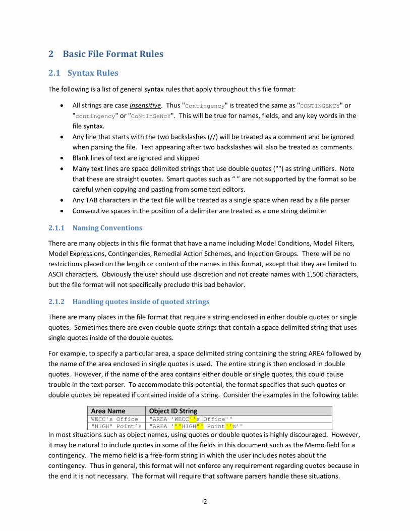
2.1.2 Handling quotes inside of quoted strings
There are many places in the file format that require a string enclosed in either double quotes or single quotes. Sometimes there are even double quote strings that contain a space delimited string that uses single quotes inside of the double quotes.
For example, to specify a particular area, a space delimited string containing the string AREA followed by the name of the area enclosed in single quotes is used. The entire string is then enclosed in double quotes. However, if the name of the area contains either double or single quotes, this could cause trouble in the text parser. To accommodate this potential, the format specifies that such quotes or double quotes be repeated if contained inside of a string. Consider the examples in the following table:
Area Name Object ID String WECC's Office "AREA 'WECC''s Office'" "HIGH" Point’s "AREA '""HIGH"" Point''s'"
In most situations such as object names, using quotes or double quotes is highly discouraged. However, it may be natural to include quotes in some of the fields in this document such as the Memo field for a contingency. The memo field is a free-form string in which the user includes notes about the contingency. Thus in general, this format will not enforce any requirement regarding quotes because in the end it is not necessary. The format will require that software parsers handle these situations.

3
2.2 Object Type Strings
There are many places in this file format where a particular object type must be referenced. All object type strings must not contain any spaces. The following is a list of some of the allowable object types:
Branch, Bus, Gen, Shunt, Load, Area, Zone, Substation, InjectionGroup, Interface, 3WXFormer, DCTransmissionLine, LineShunt, VSCDCLine, ModelExpression, Contingency, ContingencyElement, TSContingency, TSContingencyElement, RemedialAction, RemedialActionElement, CTG_Options_Value, Sim_Solution_Options_Value, LimitSet, CustomMonitor, ModelFilter, ModelFilterCondition, ModelCondition, ModelConditionCondition, Filter, Condition
2.2.1 Branch Objects (2-terminal AC devices)
An object type BRANCH signifies either an AC transmission line, 2-winding transformer, a series capacitor or reactor, or any AC device which connects two buses. Within a BRANCH there is then a field BranchDeviceType which can have the following entries: Line, Transformer, Series Cap, Breaker, Disconnect, ZBR, Fuse, Load Break Disconnect, or Ground Disconnect. This enumeration of device types comes from the Common Information Model (CIM) specification, except that a ZBR is called a Jumper in CIM. In general a user may toggle between these various device types, with the exception of a Transformer. Once an object is specified as a transformer it may not be turned back into a another branch device type.
2.3 Specifying an object using a string
There are many places in this file format where a particular object must be referenced. In these situations a string will be specified that is enclosed in double quotes. The object string will be space delimited with the first string representing the object type. Object type strings from Section 2.2 will never have spaces in them. Following the object type string there will be identification information for the object. This information allows for three potential formats that the software will need to parse: Primary Keys, Secondary Keys, or Labels. While each object can have labels, each different object type can have a different number of key fields. The key fields for the various object types are as follows:
Object Type Primary Key Fields Secondary Key Fields Gen BusNum
ID BusNameNomkV ID
Bus Number NameNomkV Branch BusNumFrom
BusNumTo Circuit
BusNameNomkVFrom BusNameNomkVTo Circuit
Branch (Special treatment for interacting with Branches using the EPC format)
MSBusNumFrom MSBusNumTo Circuit Section
MSBusNameNomkVFrom MSBusNameNomkVTo Circuit Section
Load BusNum ID
BusNameNomkV ID

4
Shunt BusNum ID
BusNameNomkV ID
Area Number Name Zone Number Name Substation Number Name InjectionGroup Name none available Interface Name Number 3WXformer BusNumPri
BusNumSec BusNumTer Circuit
BusNameNomkVPri BusNameNomkVSec BusNameNomkVTer Circuit
DCTransmissionLine BusNumRect BusNumInv Circuit
BusNameNomkVRect BusNameNomkVInv Circuit
LineShunt BusNumFrom BusNumTo BusNumLoc Circuit ID
BusNameNomkVFrom BusNameNomkVTo BusNameNomkVLoc Circuit ID
LineShunt (Special treatment for interacting with Branches using the EPC format)
MSBusNumFrom MSBusNumTo MSBusNumLoc Circuit ID Section
MSBusNameNomkVFrom MSBusNameNomkVTo MSBusNumLoc Circuit ID Section
VSCDCLine Name none available ModelExpression Name none available
2.3.1 Special Notes To Maintain Compatibility between PowerWorld and EPC Power Flow File format conventions
The feature above for using the Interface Number as a secondary key field has been added to Simulator Version 18. The Interface name remains the primary key and PowerWorld Simulator requires that the name be unique for all interfaces. Interface numbers within PowerWorld Simulator have traditionally not been maintained by our user base and as a result when writing out the information to this format, PowerWorld Simulator will always write the name of the interface. We can however read files which use the number as a key identifier.
The three-winding transformer key identifiers in PowerWorld Simulator are slightly different than what is shown in the previous table, however for the purposes of writing out and reading this format, changes have been made to PowerWorld Simulator Version 18 so that the key identifiers as shown in the table can be used. This makes the format more consistent with those used by PSS/E and PSLF.

5
2.3.2 Special Note on Branch and LineShunt objects and Multi-Section Lines
In PowerWorld Simulator as well as PSS/E RAW files, branch records have 3 unique identifiers: “from bus”, “to bus”, and “circuit ID”. There is also a concept of a multi-section line, but this is purely an aggregation object that groups together a series of branches whose statuses are coordinated. Thus within a multi-section line, when one branch changes status, then all branches within the multi-section line group change status to stay coordinated with other branches. The unique identifiers within the various branches in the multi-section line include the intermediate bus numbers or name/kv combinations.
Within a PSLF EPC file format however, the concept of a multi-section line is fundamentally embedded within the concept of the EPC format’s branch record. Thus instead of only 3 identifiers, there are 4 identifiers for a branch within the EPC format: “from bus”, “to bus”, “circuit ID”, and “section number”. There can then be a number of sections that traverse the from bus toward the to bus.
As an example, consider the multi-section line shown below which has 7 sections in series that traverse from bus 40489 to 40687. Normally within PowerWorld Simulator (and a PSS/E RAW file) the 4th section would be identified as "Branch 40704 40706 2". Within GE PSLF however, this branch would instead be identified as "Branch 40489 40687 2 4". Both of these have the same meaning but there are fundamental differences in the identifiers used.
This is something that must be managed by this format. To be consistent with the file format traditionally used within WECC to transfer power flow data between members (which is the EPC file), the format described in this document will force consistency with the EPC file concept of a branch record. The intermediate bus numbers 40700 through 40710 above would not appear in the EPC file format at all and thus are not part of the normal WECC data formats. Because this format does not create any branches, but only refers to branches to define contingency events, model conditions, and so forth, this can be achieved within the PowerWorld structure and is achievable by any other software tool which manages multi-section line records. If the file format involved the creation of branches then this would be more troublesome, but for the RAS and contingency format this is acceptable.
Therefore, anywhere that a branch is referred to using the object ID string with primary or secondary keys as described in the following sections, if the branch is part of a multi-section line, then 4 identifiers must be used and parsed accordingly. For branches that are not part of a multi-section line when reading in a file in this format the parser must handle the omission of the identifier if it’s not needed. In
6
addition a parser must be able to ignore this 4th identifier in a file if it’s not needed. When identifying branches using labels this is not relevant and the object ID string is simply "Branch 'My Label'".
A similar convention will be used for the LineShunt object. If a line shunt exists with Shunt ID “A” at bus 40706 at Section 6 of the multi-section line as shown in the picture above, then normally PowerWorld Simulator would refer to this Line Shunt as "LineShunt 40708 40710 40708 2 A". To maintain compatibility with the treatment of multi-section lines in the EPC file format this must be expressed instead as "LineShunt 40489 40687 40489 2 A 6". The Section ID has been appended to the end of the key field lists. Also note that the 3rd identifier shows the terminal bus identifier for the multi-section line record which is on the same side as the line shunt relative to its branch.
Again, anywhere that a LineShunt is referred to using the object ID string with primary or secondary keys as described in the following sections, if the branch to which the LineShunt is connected is part of a multi-section line, then 6 identifiers must be used and parsed accordingly instead of 5. Note that when identifying line shunts using labels this is not relevant and the object ID string would be simply "LineShunt 'My Label String'".
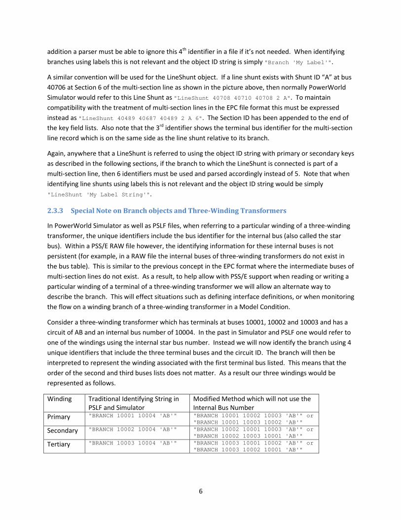
2.3.3 Special Note on Branch objects and Three-Winding Transformers
In PowerWorld Simulator as well as PSLF files, when referring to a particular winding of a three-winding transformer, the unique identifiers include the bus identifier for the internal bus (also called the star bus). Within a PSS/E RAW file however, the identifying information for these internal buses is not persistent (for example, in a RAW file the internal buses of three-winding transformers do not exist in the bus table). This is similar to the previous concept in the EPC format where the intermediate buses of multi-section lines do not exist. As a result, to help allow with PSS/E support when reading or writing a particular winding of a terminal of a three-winding transformer we will allow an alternate way to describe the branch. This will effect situations such as defining interface definitions, or when monitoring the flow on a winding branch of a three-winding transformer in a Model Condition.
Consider a three-winding transformer which has terminals at buses 10001, 10002 and 10003 and has a circuit of AB and an internal bus number of 10004. In the past in Simulator and PSLF one would refer to one of the windings using the internal star bus number. Instead we will now identify the branch using 4 unique identifiers that include the three terminal buses and the circuit ID. The branch will then be interpreted to represent the winding associated with the first terminal bus listed. This means that the order of the second and third buses lists does not matter. As a result our three windings would be represented as follows.
Winding Traditional Identifying String in PSLF and Simulator
Modified Method which will not use the Internal Bus Number
Primary "BRANCH 10001 10004 'AB'" "BRANCH 10001 10002 10003 'AB'" or "BRANCH 10001 10003 10002 'AB'"
Secondary "BRANCH 10002 10004 'AB'" "BRANCH 10002 10001 10003 'AB'" or "BRANCH 10002 10003 10001 'AB'"
Tertiary "BRANCH 10003 10004 'AB'" "BRANCH 10003 10001 10002 'AB'" or "BRANCH 10003 10002 10001 'AB'"
7
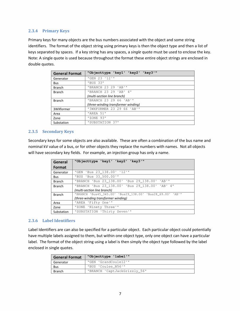
2.3.4 Primary Keys
Primary keys for many objects are the bus numbers associated with the object and some string identifiers. The format of the object string using primary keys is then the object type and then a list of keys separated by spaces. If a key string has any spaces, a single quote must be used to enclose the key. Note: A single quote is used because throughout the format these entire object strings are enclosed in double quotes.
General Format "Objecttype 'key1' 'key2' 'key3'" Generator "GEN 23 '12'" Bus "BUS 33" Branch "BRANCH 23 29 'AB'" Branch "BRANCH 23 29 'AB' 4"
(multi-section line branch) Branch "BRANCH 23 29 66 'AB'"
(three-winding transformer winding) 3WXformer "3WXFORMER 23 29 66 'AB'" Area "AREA 51" Zone "ZONE 93" Substation "SUBSTATION 37"
2.3.5 Secondary Keys
Secondary keys for some objects are also available. These are often a combination of the bus name and nominal kV value of a bus, or for other objects they replace the numbers with names. Not all objects will have secondary key fields. For example, an injection group has only a name.
General Format
"Objecttype 'key1' 'key2' 'key3'"
Generator "GEN 'Bus 23_138.00' '12'" Bus "BUS 'Bus 33_500.00'" Branch "BRANCH 'Bus 23_138.00' 'Bus 29_138.00' 'AB'" Branch "BRANCH 'Bus 23_138.00' 'Bus 29_138.00' 'AB' 4"
(multi-section line branch) Branch "BRANCH 'Bus45_345.00' 'Bus29_138.00' 'Bus28_69.00' 'AB'"
(three-winding transformer winding) Area "AREA 'Fifty One'" Zone "ZONE 'Ninety Three'" Substation "SUBSTATION 'Thirty Seven'"
2.3.6 Label Identifiers
Label Identifiers are can also be specified for a particular object. Each particular object could potentially have multiple labels assigned to them, but within one object type, only one object can have a particular label. The format of the object string using a label is then simply the object type followed by the label enclosed in single quotes.
General Format "Objecttype 'label'" Generator "GEN 'GrandCoule12'" Bus "BUS 'Coulee_N56'" Branch "BRANCH 'CaptJackGrizzly_56"

8
2.3.7 Naming Collisions
It is possible in this format for a power system model to have secondary fields which do not create a unique identifier for the case. For example, the secondary key fields for buses are the concatenation of the Name and Nominal kV. These are almost always unique, but not always. For example, a recent WECC cases and there are 4 buses named CanyonGT at 13.8 kV (numbers 25211-25214). When reading from a file referencing the bus "CanyonGT_13.8", this format would just pick the one that a software vendors search routine finds first. There is no guarantee that this will be the one intended, so this is something the user must be careful with if using secondary key fields.
It is also possible for the label identifiers to collide with the secondary keys as well. Our experience in practice is that the labels are derived from unique identifiers in the EMS models which are longer than the secondary key strings and are a concatenation of the substation name(s), some unique delimiter like a $. Thus in practice this shouldn’t happen, but it is possible.
It is even possible with labels that there could be a conflict between the primary key and the label. We do not expect to see too many buses with a label of “1234”, but a user could do something like that.
Regardless of these hypothetical limitations, when parsing these strings, this format instructs that software parsers will always look first for the primary keys, then the secondary keys, and finally for any of the labels. Thus if there is a conflict between secondary keys and the labels, then the secondary key will have precedence.
2.4 Object Field Definitions
The following is the start of a list of fields that will be defined for each object type. Collaboration between WECC members, PowerWorld Corporation staff, and other software vendor staff will more fully define which fields are necessary for modeling purposes of contingency analysis. Adding new variables to the parsing will be trivial for the software vendors so we will add them as requested.
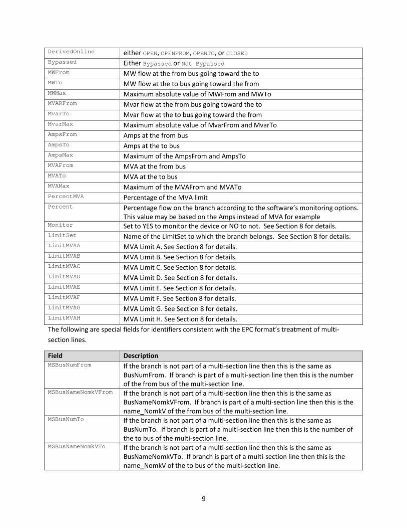
2.4.1 Branch and MSBranch Fields
Field Description BusNumFrom Number of the from bus BusNameFrom Name of the from bus BusNameNomkVFrom Combination of the Name and the kV of the from bus separated by an
underscore. For example “Johnson_34.5” BusNumTo Number of the to bus BusNameTo Name of the to bus BusNameNomkVTo Combination of the Name and the kV of the to bus separated by an
underscore. For example “Johnson_34.5” Circuit Circuit ID of the branch Status either OPEN or CLOSED DerivedStatus either OPEN, OPENFROM, OPENTO, or CLOSED Online YES or NO
9
DerivedOnline either OPEN, OPENFROM, OPENTO, or CLOSED Bypassed Either Bypassed or Not Bypassed MWFrom MW flow at the from bus going toward the to MWTo MW flow at the to bus going toward the from MWMax Maximum absolute value of MWFrom and MWTo MVARFrom Mvar flow at the from bus going toward the to MvarTo Mvar flow at the to bus going toward the from MvarMax Maximum absolute value of MvarFrom and MvarTo AmpsFrom Amps at the from bus AmpsTo Amps at the to bus AmpsMax Maximum of the AmpsFrom and AmpsTo MVAFrom MVA at the from bus MVATo MVA at the to bus MVAMax Maximum of the MVAFrom and MVATo PercentMVA Percentage of the MVA limit Percent Percentage flow on the branch according to the software’s monitoring options.
This value may be based on the Amps instead of MVA for example Monitor Set to YES to monitor the device or NO to not. See Section 8 for details. LimitSet Name of the LimitSet to which the branch belongs. See Section 8 for details. LimitMVAA MVA Limit A. See Section 8 for details. LimitMVAB MVA Limit B. See Section 8 for details. LimitMVAC MVA Limit C. See Section 8 for details. LimitMVAD MVA Limit D. See Section 8 for details. LimitMVAE MVA Limit E. See Section 8 for details. LimitMVAF MVA Limit F. See Section 8 for details. LimitMVAG MVA Limit G. See Section 8 for details. LimitMVAH MVA Limit H. See Section 8 for details. The following are special fields for identifiers consistent with the EPC format’s treatment of multi-section lines.
Field Description MSBusNumFrom If the branch is not part of a multi-section line then this is the same as
BusNumFrom. If branch is part of a multi-section line then this is the number of the from bus of the multi-section line.
MSBusNameNomkVFrom If the branch is not part of a multi-section line then this is the same as BusNameNomkVFrom. If branch is part of a multi-section line then this is the name_NomkV of the from bus of the multi-section line.
MSBusNumTo If the branch is not part of a multi-section line then this is the same as BusNumTo. If branch is part of a multi-section line then this is the number of the to bus of the multi-section line.
MSBusNameNomkVTo If the branch is not part of a multi-section line then this is the same as BusNameNomkVTo. If branch is part of a multi-section line then this is the name_NomkV of the to bus of the multi-section line.

10
Section If the branch is not part of a multi-section line this entry is blank. If branch is part of a multi-section line, this is the section number within the multi-section line.
2.4.2 Bus Fields
Field Description Number Number of the bus Name Name of the bus NameNomkV Combination of the Name and the kV of the bus separated by an underscore. For
example “Johnson_34.5” Status Either DISCONNECTED or CONNECTED Vpu The per unit voltage magnitude of the bus Vangle The angle of the bus in degrees kV The voltage magnitude in kilovolts NomkV The nominal voltage of the bus in kilovolts LoadMW The total load at the bus in MW. If there are no loads defined at the bus then
this value is blank. LoadMvar The total load at the bus in Mvar. If there are no loads defined at the bus then
this value is blank. GenMW The total generation at the bus in MW. If there are no generators defined at the
bus then this value is blank. GenMvar The total generation at the bus in Mvar. If there are no generators defined at the
bus, value is blank. GenMWMax The sum of generation Max MW at the bus. If there are no generators defined at
the bus, value is blank. GenMWMin The sum of generation Min MW at the bus. If there are no generators defined at
the bus, value is blank. GenMvarMax The sum of generation Max Mvar at the bus. If there are no generators defined
at the bus, value is blank. GenMvarMin The sum of generation Min Mvar at the bus. If there are no generators defined
at the bus, value is blank. ShuntMvar The total switched shunt (both svd and bus) at the bus in Mvar. If there are no
shunts (svd or bus) defined at the bus, value is blank. Monitor Set to NO to signify that the bus should not be monitored. Set to YES to make it
eligible for monitoring as described in Section 8. LimitSet Set to the name of the Limit Set to which the Bus belongs. See Section 8 for
details. UseSpecificLimits Set to YES to signify that the bus has its own limits specified by
LimitHighA…LimitHighD and LimitLowA…LimitLowD. See Section 8 for details. LimitHighA High voltage limit A. See Section 8 for details. LimitHighB High voltage limit B. See Section 8 for details. LimitHighC High voltage limit C. See Section 8 for details. LimitHighD High voltage limit D. See Section 8 for details. LimitLowA Low voltage limit A. See Section 8 for details. LimitLowB Low voltage limit B. See Section 8 for details.
11
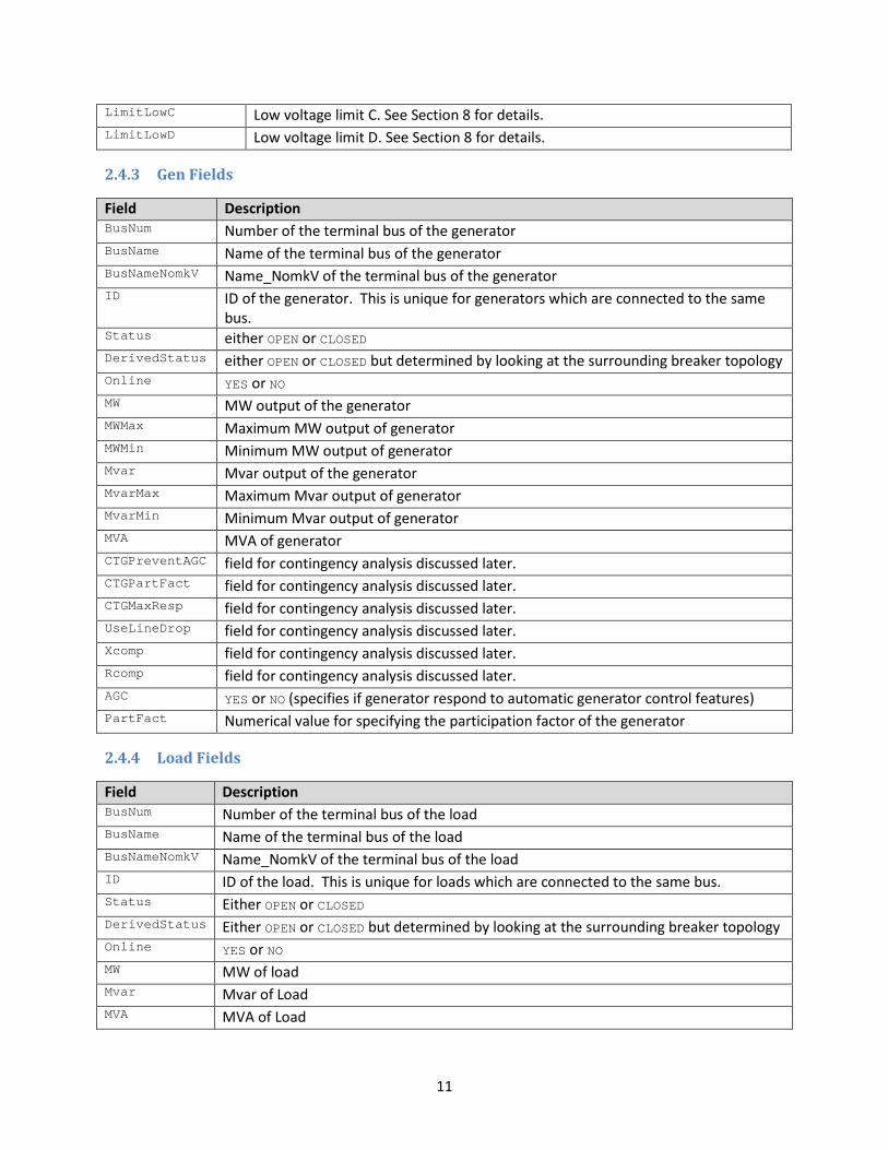
LimitLowC Low voltage limit C. See Section 8 for details. LimitLowD Low voltage limit D. See Section 8 for details.
2.4.3 Gen Fields
Field Description BusNum Number of the terminal bus of the generator BusName Name of the terminal bus of the generator BusNameNomkV Name_NomkV of the terminal bus of the generator ID ID of the generator. This is unique for generators which are connected to the same
bus. Status either OPEN or CLOSED DerivedStatus either OPEN or CLOSED but determined by looking at the surrounding breaker topology Online YES or NO MW MW output of the generator MWMax Maximum MW output of generator MWMin Minimum MW output of generator Mvar Mvar output of the generator MvarMax Maximum Mvar output of generator MvarMin Minimum Mvar output of generator MVA MVA of generator CTGPreventAGC field for contingency analysis discussed later. CTGPartFact field for contingency analysis discussed later. CTGMaxResp field for contingency analysis discussed later. UseLineDrop field for contingency analysis discussed later. Xcomp field for contingency analysis discussed later. Rcomp field for contingency analysis discussed later. AGC YES or NO (specifies if generator respond to automatic generator control features) PartFact Numerical value for specifying the participation factor of the generator
2.4.4 Load Fields
Field Description BusNum Number of the terminal bus of the load BusName Name of the terminal bus of the load BusNameNomkV Name_NomkV of the terminal bus of the load ID ID of the load. This is unique for loads which are connected to the same bus. Status Either OPEN or CLOSED DerivedStatus Either OPEN or CLOSED but determined by looking at the surrounding breaker topology Online YES or NO MW MW of load Mvar Mvar of Load MVA MVA of Load
12
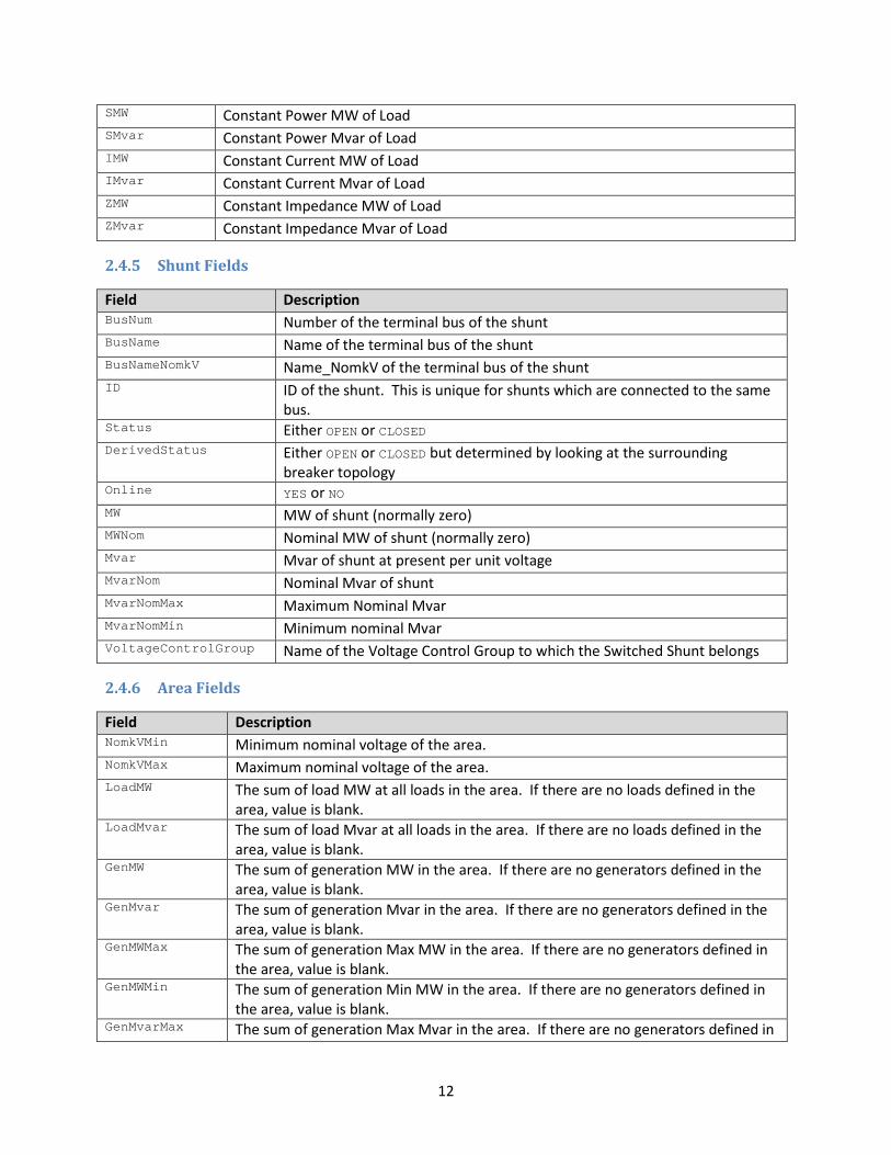
SMW Constant Power MW of Load SMvar Constant Power Mvar of Load IMW Constant Current MW of Load IMvar Constant Current Mvar of Load ZMW Constant Impedance MW of Load ZMvar Constant Impedance Mvar of Load
2.4.5 Shunt Fields
Field Description BusNum Number of the terminal bus of the shunt BusName Name of the terminal bus of the shunt BusNameNomkV Name_NomkV of the terminal bus of the shunt ID ID of the shunt. This is unique for shunts which are connected to the same
bus. Status Either OPEN or CLOSED DerivedStatus Either OPEN or CLOSED but determined by looking at the surrounding
breaker topology Online YES or NO MW MW of shunt (normally zero) MWNom Nominal MW of shunt (normally zero) Mvar Mvar of shunt at present per unit voltage MvarNom Nominal Mvar of shunt MvarNomMax Maximum Nominal Mvar MvarNomMin Minimum nominal Mvar VoltageControlGroup Name of the Voltage Control Group to which the Switched Shunt belongs
2.4.6 Area Fields
Field Description NomkVMin Minimum nominal voltage of the area. NomkVMax Maximum nominal voltage of the area. LoadMW The sum of load MW at all loads in the area. If there are no loads defined in the
area, value is blank. LoadMvar The sum of load Mvar at all loads in the area. If there are no loads defined in the
area, value is blank. GenMW The sum of generation MW in the area. If there are no generators defined in the
area, value is blank. GenMvar The sum of generation Mvar in the area. If there are no generators defined in the
area, value is blank. GenMWMax The sum of generation Max MW in the area. If there are no generators defined in
the area, value is blank. GenMWMin The sum of generation Min MW in the area. If there are no generators defined in
the area, value is blank. GenMvarMax The sum of generation Max Mvar in the area. If there are no generators defined in

13
the area, value is blank. GenMvarMin The sum of generation Min Mvar in the area. If there are no generators defined in
the area, value is blank. MonitorLimits YES or NO to monitor limits in this area MonitorMinkV Minimum nominal kV that will be monitored MonitorMaxkV Minimum nominal kV that will be monitored CTGMakeupGen field for contingency analysis discussed later.
2.4.7 Zone Fields
Field Description NomkVMin Minimum nominal voltage of the zone. NomkVMax Maximum nominal voltage of the zone. LoadMW The sum of load MW at all loads in the zone. If there are no loads defined in the
zone, value is blank. LoadMvar The sum of load Mvar at all loads in the zone. If there are no loads defined in the
zone, value is blank. GenMW The sum of generation MW in the zone. If there are no generators defined in the
zone, value is blank. GenMvar The sum of generation Mvar in the zone. If there are no generators defined in the
zone, value is blank. GenMWMax The sum of generation Max MW in the zone. If there are no generators defined in
the zone, value is blank. GenMWMin The sum of generation Min MW in the zone. If there are no generators defined in
the zone, value is blank. GenMvarMax The sum of generation Max Mvar in the zone. If there are no generators defined in
the zone, value is blank. GenMvarMin The sum of generation Min Mvar in the zone. If there are no generators defined in
the zone, value is blank. MonitorLimits YES or NO to monitor limits in this zone MonitorMinkV Minimum nominal kV that will be monitored MonitorMaxkV Minimum nominal kV that will be monitored
2.4.8 Substation Fields
Field Description NomkVMin Minimum nominal voltage of the substation. NomkVMax Maximum nominal voltage of the substation. LoadMW The sum of load MW at all loads in the substation. If there are no loads defined in
the substation, value is blank. LoadMvar The sum of load Mvar at all loads in the substation. If there are no loads defined in
the substation, value is blank. GenMW The sum of generation MW in the substation. If there are no generators defined in
the substation, value is blank. GenMvar The sum of generation Mvar in the substation. If there are no generators defined in
the substation, value is blank.
14
GenMWMax The sum of generation Max MW in the substation. If there are no generators defined in the substation, value is blank.
GenMWMin The sum of generation Min MW in the substation. If there are no generators defined in the substation, value is blank.
GenMvarMax The sum of generation Max Mvar in the substation. If there are no generators defined in the substation, value is blank.
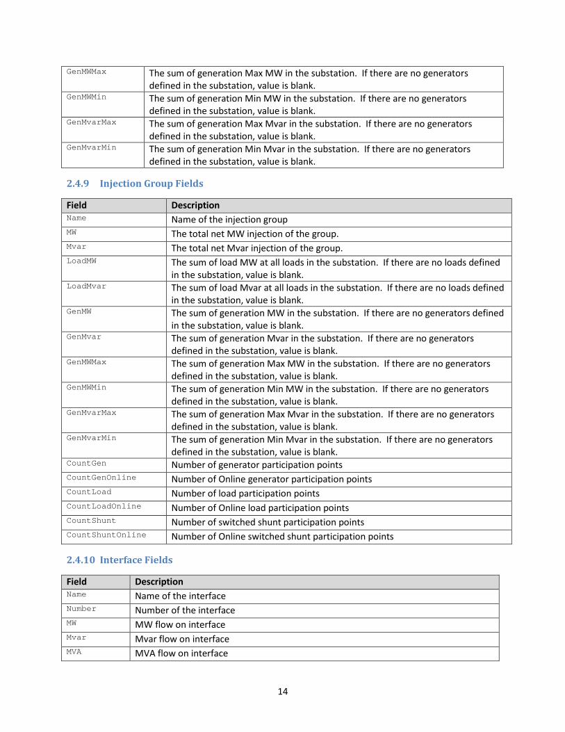
GenMvarMin The sum of generation Min Mvar in the substation. If there are no generators defined in the substation, value is blank.
2.4.9 Injection Group Fields
Field Description Name Name of the injection group MW The total net MW injection of the group. Mvar The total net Mvar injection of the group. LoadMW The sum of load MW at all loads in the substation. If there are no loads defined
in the substation, value is blank. LoadMvar The sum of load Mvar at all loads in the substation. If there are no loads defined
in the substation, value is blank. GenMW The sum of generation MW in the substation. If there are no generators defined
in the substation, value is blank. GenMvar The sum of generation Mvar in the substation. If there are no generators
defined in the substation, value is blank. GenMWMax The sum of generation Max MW in the substation. If there are no generators
defined in the substation, value is blank. GenMWMin The sum of generation Min MW in the substation. If there are no generators
defined in the substation, value is blank. GenMvarMax The sum of generation Max Mvar in the substation. If there are no generators
defined in the substation, value is blank. GenMvarMin The sum of generation Min Mvar in the substation. If there are no generators
defined in the substation, value is blank. CountGen Number of generator participation points CountGenOnline Number of Online generator participation points CountLoad Number of load participation points CountLoadOnline Number of Online load participation points CountShunt Number of switched shunt participation points CountShuntOnline Number of Online switched shunt participation points
2.4.10 Interface Fields
Field Description Name Name of the interface Number Number of the interface MW MW flow on interface Mvar Mvar flow on interface MVA MVA flow on interface
15
Percent Percent of limit used on interface according to the software’s monitoring options Monitor Set to YES to monitor the device or NO to not LimitSet Name of the LimitSet to which the interface belongs LimitMWA MW Limit A. See Section 8 for details. LimitMWB MW Limit B. See Section 8 for details. LimitMWC MW Limit C. See Section 8 for details. LimitMWD MW Limit D. See Section 8 for details. LimitMWE MW Limit E. See Section 8 for details. LimitMWF MW Limit F. See Section 8 for details. LimitMWG MW Limit G. See Section 8 for details. LimitMWH MW Limit H. See Section 8 for details.
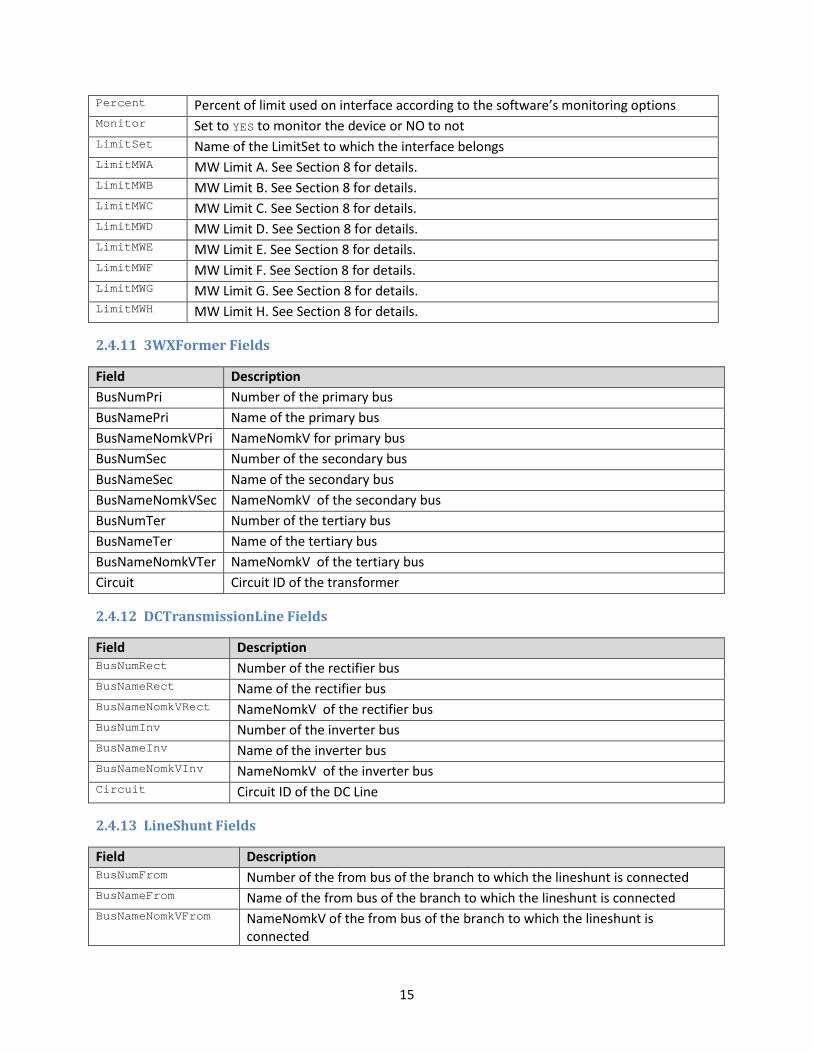
2.4.11 3WXFormer Fields
Field Description BusNumPri Number of the primary bus BusNamePri Name of the primary bus BusNameNomkVPri NameNomkV for primary bus BusNumSec Number of the secondary bus BusNameSec Name of the secondary bus BusNameNomkVSec NameNomkV of the secondary bus BusNumTer Number of the tertiary bus BusNameTer Name of the tertiary bus BusNameNomkVTer NameNomkV of the tertiary bus Circuit Circuit ID of the transformer
2.4.12 DCTransmissionLine Fields
Field Description BusNumRect Number of the rectifier bus BusNameRect Name of the rectifier bus BusNameNomkVRect NameNomkV of the rectifier bus BusNumInv Number of the inverter bus BusNameInv Name of the inverter bus BusNameNomkVInv NameNomkV of the inverter bus Circuit Circuit ID of the DC Line
2.4.13 LineShunt Fields
Field Description BusNumFrom Number of the from bus of the branch to which the lineshunt is connected BusNameFrom Name of the from bus of the branch to which the lineshunt is connected BusNameNomkVFrom NameNomkV of the from bus of the branch to which the lineshunt is
connected
16
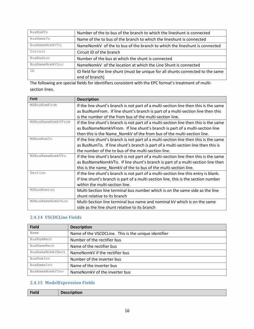
BusNumTo Number of the to bus of the branch to which the lineshunt is connected BusNameTo Name of the to bus of the branch to which the lineshunt is connected BusNameNomkVTo NameNomkV of the to bus of the branch to which the lineshunt is connected Circuit Circuit ID of the branch BusNumLoc Number of the bus at which the shunt is connected BusNameNomkVLoc NameNomkV of the location at which the Line Shunt is connected ID ID field for the line shunt (must be unique for all shunts connected to the same
end of branch) The following are special fields for identifiers consistent with the EPC format’s treatment of multi-section lines.
Field Description MSBusNumFrom If the line shunt’s branch is not part of a multi-section line then this is the same
as BusNumFrom. If line shunt’s branch is part of a multi-section line then this is the number of the from bus of the multi-section line.
MSBusNameNomkVFrom If the line shunt’s branch is not part of a multi-section line then this is the same as BusNameNomkVFrom. If line shunt’s branch is part of a multi-section line then this is the Name_NomkV of the from bus of the multi-section line.
MSBusNumTo If the line shunt’s branch is not part of a multi-section line then this is the same as BusNumTo. If line shunt’s branch is part of a multi-section line then this is the number of the to bus of the multi-section line.
MSBusNameNomkVTo If the line shunt’s branch is not part of a multi-section line then this is the same as BusNameNomkVTo. If line shunt’s branch is part of a multi-section line then this is the name_NomkV of the to bus of the multi-section line.
Section If the line shunt’s branch is not part of a multi-section line this entry is blank. If line shunt’s branch is part of a multi-section line, this is the section number within the multi-section line.
MSBusNumLoc Multi-Section line terminal bus number which is on the same side as the line shunt relative to its branch
MSBusNameNomkVLoc Multi-Section line terminal bus name and nominal kV which is on the same side as the line shunt relative to its branch
2.4.14 VSCDCLine Fields
Field Description Name Name of the VSCDCLine. This is the unique identifier BusNumRect Number of the rectifier bus BusNameRect Name of the rectifier bus BusNameNomkVRect NameNomkV if the rectifier bus BusNumInv Number of the inverter bus BusNameInv Name of the inverter bus BusNameNomkVInv NameNomkV of the inverter bus
2.4.15 ModelExpression Fields
Field Description

17
Expression The result of the model expression evaluation
2.4.16 VoltageControlGroup Fields
Field Description Name The name of the voltage control group Status Status of the group. Set to one of the following three choices: ON, OFF, or FORCEON
These will be discussed more a later section
2.4.17 Model Filter Fields
Field Description Name Name of the Model Filter contained in double quotes. Note: Names must be unique
across all other ModelFilters and ModelConditions. Memo Extra String Meets Value will be YES if the Model Filter logic evaluates to TRUE in the present system
state.
2.4.18 Model Condition Fields
Field Description Name Name of the Model Condition contained in double quotes. Note: Names must be
unique across all other ModelFilters and ModelConditions. Memo Extra String Meets Value will be YES if the Model Condition logic evaluates to TRUE in the present
system state.
18
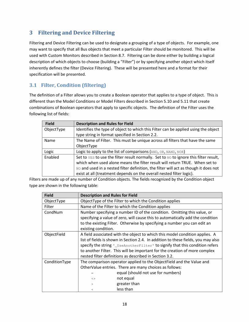
3 Filtering and Device Filtering
Filtering and Device Filtering can be used to designate a grouping of a type of objects. For example, one may want to specify that all Bus objects that meet a particular Filter should be monitored. This will be used with Custom Monitors described in Section 8.7. Filtering can be done either by building a logical description of which objects to choose (building a “Filter”) or by specifying another object which itself inherently defines the filter (Device Filtering). These will be presented here and a format for their specification will be presented.
3.1 Filter, Condition (filtering)
The definition of a Filter allows you to create a Boolean operator that applies to a type of object. This is different than the Model Conditions or Model Filters described in Section 5.10 and 5.11 that create combinations of Boolean operators that apply to specific objects. The definition of the Filter uses the following list of fields:
Field Description and Rules for Field ObjectType Identifies the type of object to which this Filter can be applied using the object
type string in format specified in Section 2.2. Name The Name of Filter. This must be unique across all filters that have the same
ObjectType Logic Logic to apply to the list of comparisons (AND, OR, NAND, NOR) Enabled Set to YES to use the filter result normally. Set to NO to ignore this filter result,
which when used alone means the filter result will return TRUE. When set to NO and used in a nested filter definition, the filter will act as though it does not exist at all (treatment depends on the overall nested filter logic).
Filters are made up of any number of Condition objects. The fields recognized by the Condition object type are shown in the following table:
Field Description and Rules for Field ObjectType ObjectType of the Filter to which the Condition applies Filter Name of the Filter to which the Condition applies CondNum Number specifying a number ID of the condition. Omitting this value, or
specifying a value of zero, will cause this to automatically add the condition to the existing Filter. Otherwise by specifying a number you can edit an existing condition.
ObjectField A field associated with the object to which this model condition applies. A list of fields is shown in Section 2.4. In addition to these fields, you may also specify the string "_UseAnotherFilter" to signify that this condition refers to another Filter. This will be important for the creation of more complex nested filter definitions as described in Section 3.2.
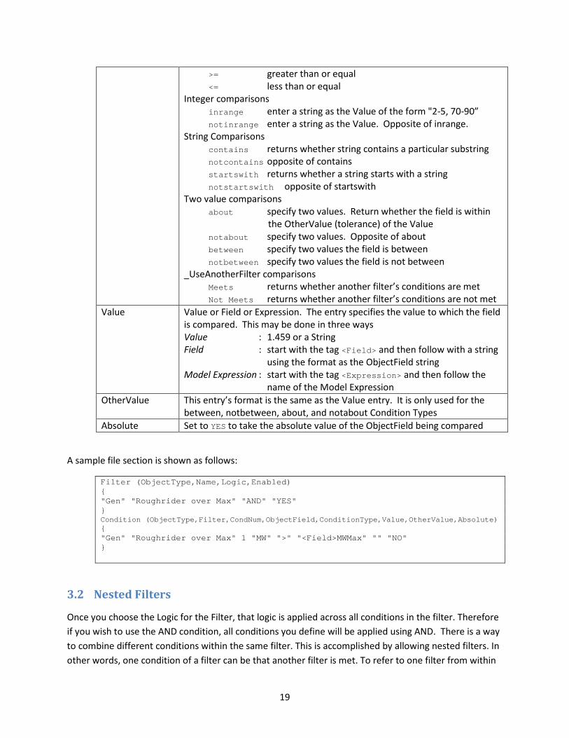
ConditionType The comparison operator applied to the ObjectField and the Value and OtherValue entries. There are many choices as follows: = equal (should not use for numbers) <> not equal > greater than < less than
19
>= greater than or equal <= less than or equal Integer comparisons inrange enter a string as the Value of the form "2-5, 70-90” notinrange enter a string as the Value. Opposite of inrange. String Comparisons contains returns whether string contains a particular substring notcontains opposite of contains startswith returns whether a string starts with a string notstartswith opposite of startswith Two value comparisons about specify two values. Return whether the field is within
the OtherValue (tolerance) of the Value notabout specify two values. Opposite of about between specify two values the field is between notbetween specify two values the field is not between _UseAnotherFilter comparisons Meets returns whether another filter’s conditions are met Not Meets returns whether another filter’s conditions are not met
Value
Value or Field or Expression. The entry specifies the value to which the field is compared. This may be done in three ways Value : 1.459 or a String Field : start with the tag <Field> and then follow with a string
using the format as the ObjectField string Model Expression : start with the tag <Expression> and then follow the
name of the Model Expression OtherValue This entry’s format is the same as the Value entry. It is only used for the
between, notbetween, about, and notabout Condition Types Absolute Set to YES to take the absolute value of the ObjectField being compared
A sample file section is shown as follows:
Filter (ObjectType,Name,Logic,Enabled) { "Gen" "Roughrider over Max" "AND" "YES" } Condition (ObjectType,Filter,CondNum,ObjectField,ConditionType,Value,OtherValue,Absolute) { "Gen" "Roughrider over Max" 1 "MW" ">" "<Field>MWMax" "" "NO" }
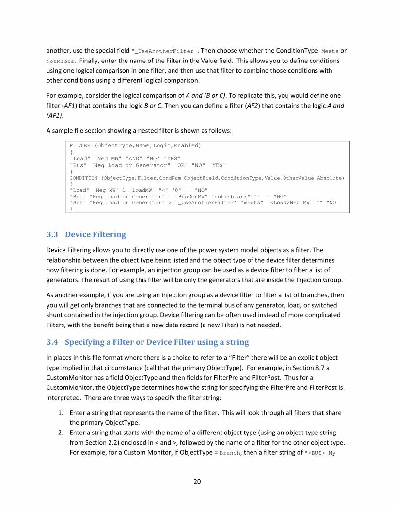
3.2 Nested Filters
Once you choose the Logic for the Filter, that logic is applied across all conditions in the filter. Therefore if you wish to use the AND condition, all conditions you define will be applied using AND. There is a way to combine different conditions within the same filter. This is accomplished by allowing nested filters. In other words, one condition of a filter can be that another filter is met. To refer to one filter from within
20
another, use the special field "_UseAnotherFilter". Then choose whether the ConditionType Meets or NotMeets. Finally, enter the name of the Filter in the Value field. This allows you to define conditions using one logical comparison in one filter, and then use that filter to combine those conditions with other conditions using a different logical comparison.
For example, consider the logical comparison of A and (B or C). To replicate this, you would define one filter (AF1) that contains the logic B or C. Then you can define a filter (AF2) that contains the logic A and (AF1).
A sample file section showing a nested filter is shown as follows:
FILTER (ObjectType,Name,Logic,Enabled) { "Load" "Neg MW" "AND" "NO" "YES" "Bus" "Neg Load or Generator" "OR" "NO" "YES" } CONDITION (ObjectType,Filter,CondNum,ObjectField,ConditionType,Value,OtherValue,Absolute) { "Load" "Neg MW" 1 "LoadMW" "<" "0" "" "NO" "Bus" "Neg Load or Generator" 1 "BusGenMW" "notisblank" "" "" "NO" "Bus" "Neg Load or Generator" 2 "_UseAnotherFilter" "meets" "<Load>Neg MW" "" "NO" }
3.3 Device Filtering
Device Filtering allows you to directly use one of the power system model objects as a filter. The relationship between the object type being listed and the object type of the device filter determines how filtering is done. For example, an injection group can be used as a device filter to filter a list of generators. The result of using this filter will be only the generators that are inside the Injection Group.
As another example, if you are using an injection group as a device filter to filter a list of branches, then you will get only branches that are connected to the terminal bus of any generator, load, or switched shunt contained in the injection group. Device filtering can be often used instead of more complicated Filters, with the benefit being that a new data record (a new Filter) is not needed.
3.4 Specifying a Filter or Device Filter using a string
In places in this file format where there is a choice to refer to a “Filter” there will be an explicit object type implied in that circumstance (call that the primary ObjectType). For example, in Section 8.7 a CustomMonitor has a field ObjectType and then fields for FilterPre and FilterPost. Thus for a CustomMonitor, the ObjectType determines how the string for specifying the FilterPre and FilterPost is interpreted. There are three ways to specify the filter string:
1. Enter a string that represents the name of the filter. This will look through all filters that share the primary ObjectType.
2. Enter a string that starts with the name of a different object type (using an object type string from Section 2.2) enclosed in < and >, followed by the name of a filter for the other object type. For example, for a Custom Monitor, if ObjectType = Branch, then a filter string of "<BUS> My
21
FilterName" would signify that the branches should be filtered according to the bus filter named “My FilterName”. When filtering across object types, all of the secondary object types that apply to the primary object type are evaluated against the Filter and an OR logic is applied so that if any of the secondary objects meets the filter then the primary object meets the filter.
3. When specifying a device filter, in the place that a filter name is to be expressed, simply enter the following syntax "<DEVICE> Object ID String", where Object ID String is a string of the same format as described in Section 2.3. A device filter works simply by choosing all of the primary object types that are contained in the Device referenced. For example if the primary object type is GEN, and the Device Filter is an Injection Group, then all generators that are inside the injection group will meet the device filter.
4 Script Sections to Set Defaults
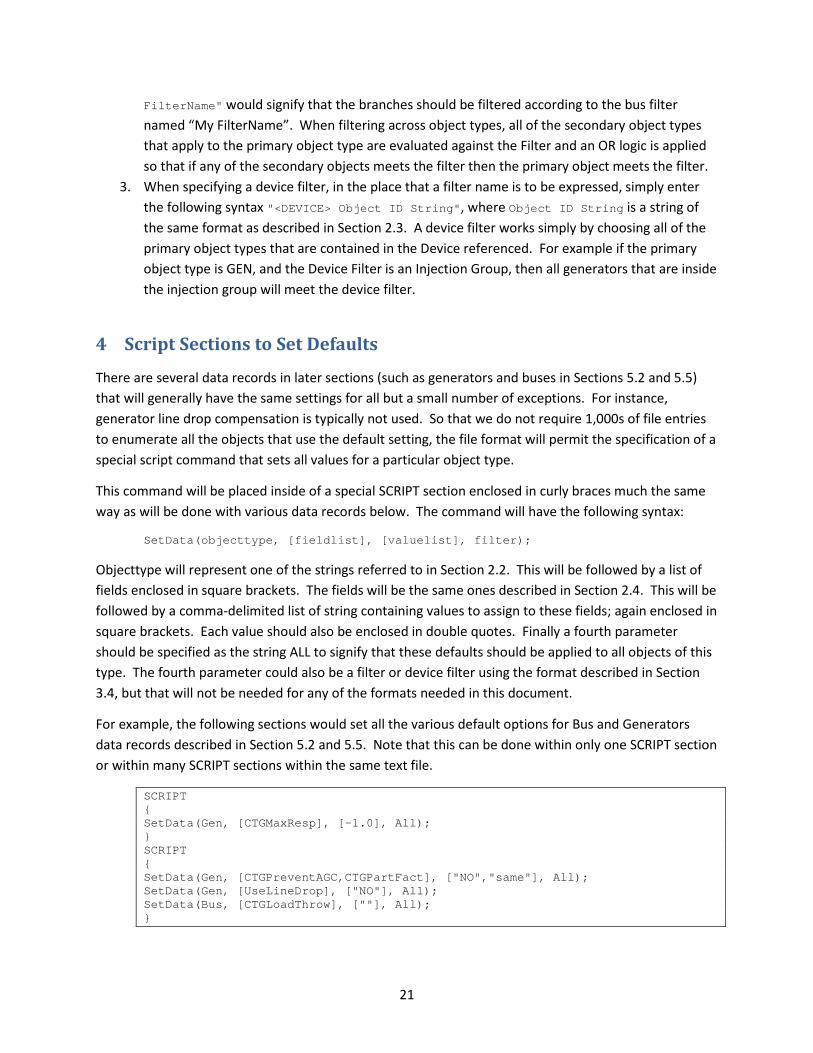
There are several data records in later sections (such as generators and buses in Sections 5.2 and 5.5) that will generally have the same settings for all but a small number of exceptions. For instance, generator line drop compensation is typically not used. So that we do not require 1,000s of file entries to enumerate all the objects that use the default setting, the file format will permit the specification of a special script command that sets all values for a particular object type.
This command will be placed inside of a special SCRIPT section enclosed in curly braces much the same way as will be done with various data records below. The command will have the following syntax:
SetData(objecttype, [fieldlist], [valuelist], filter);
Objecttype will represent one of the strings referred to in Section 2.2. This will be followed by a list of fields enclosed in square brackets. The fields will be the same ones described in Section 2.4. This will be followed by a comma-delimited list of string containing values to assign to these fields; again enclosed in square brackets. Each value should also be enclosed in double quotes. Finally a fourth parameter should be specified as the string ALL to signify that these defaults should be applied to all objects of this type. The fourth parameter could also be a filter or device filter using the format described in Section 3.4, but that will not be needed for any of the formats needed in this document.
For example, the following sections would set all the various default options for Bus and Generators data records described in Section 5.2 and 5.5. Note that this can be done within only one SCRIPT section or within many SCRIPT sections within the same text file.
SCRIPT { SetData(Gen, [CTGMaxResp], [-1.0], All); } SCRIPT { SetData(Gen, [CTGPreventAGC,CTGPartFact], ["NO","same"], All); SetData(Gen, [UseLineDrop], ["NO"], All); SetData(Bus, [CTGLoadThrow], [""], All); }

22
5 Data Record Structures
There are many object type sections that will be needed for defining the data records necessary to define contingencies and RAS.
The following data records are necessary for defining the solution options and how the behavior of various objects is handled during a contingency solution:
• Area (settings for contingency modeling) • Bus (settings for contingency modeling) • Gen (settings for contingency modeling) • CTG_Options_Value • Sim_Solution_Options_Value
The following are necessary helper objects for defining the contingency records themselves:
• InjectionGroup, PartPoint • ModelExpression • ModelCondition, ModelConditionCondition • ModelFilter, ModelFilterCondition
The following are records that define the action contingency records:
• Contingency, ContingencyElement, • TSContingency, TSContingencyElement • RemedialAction, RemedialActionElement
The following are data records necessary for defining how limits are monitored during the power flow contingency analysis:
• LimitSet • Area (settings for limit monitoring) • Zone (settings for limit monitoring) • Bus (settings for limit monitoring) • Branch (settings for limit monitoring) • Interface (settings for limit monitoring) • Filter, Condition • CustomMonitor
The basic file structure will allow defining object type sections and multiple object type sections may appear in the same text file. In addition, an object type section can be repeated in the file if desired. For example, it may be convenient to list settings for an Area record related to the solution options separately from the options related to limit monitoring.

23
An object type section will be identified as a line of text that starts with its unique string which is defined in Section 2.2. This will be followed by an open parenthesis, a comma-delimited list of field names, and then a close parenthesis. The order in which the fields are listed in this comma-delimited list dictates the order in which the fields will be read from the file. Including this header makes the file easier to read and also allows for the format to grow as new fields may be needed as new features are needed for software tools in the future. This takes a small part of the XML-inspired idea of having a self-defining format, however it does not take it to the extreme which XML does by placing these field identifiers around every individual field value. This header will appear once and there can then be any number of records (a few or 10,000s) that follow the header and do not require repeated header strings.
Syntax rules regarding the list of field names are as follows:
• The list of field names may take up several lines of the text file • The list of field names should be encompassed by parenthesis ( ) • When encountering the comment string ‘//’ in one of these lines of the text file, all text to the
right is ignored but the parser will continue to read the list of fields on the next line of text • Blank lines, or lines whose first characters are ‘//’ will be ignored and not read • Field names must be separated by commas
The field names available for each object type are described in detail in the rest of the document. Note that when a software package parses this list of fields it should NOT cause a fatal file read error if it runs across a field name that is not recognized. Appropriate warning messages could be shown to the user but it should just ignore those fields and respective values in the value lists. This document will specify which fields are necessary for defining contingency and RAS related information only, but there is clearly more information available in the software tools. The assumption is that any new fields added in the future will represent optional new features for Contingency and RAS.
After the list of field names are terminated by a close parenthesis, a left curly brace { is used to signify the start of data for this object type. Following this is a list of the values for the various fields for many different objects. The values must be in the order specified in the list of field names header. To terminate this object section a right curly brace } must be entered at the start line of a line of text.
Syntax rules for the list of values are as follows:
• The value list may take up several lines of the text file. The parser will just read values until it has read the number of values specified in the list of field names.
• Each new data object must start on its own line of text (thus any extra values that may have existed on the previous line of text will be ignored, though some warning messages are recommended)
• When encountering the comment string ‘//’ in one of these lines of the text file, all text to the right of this is ignored. Comments need not be stored by the software tools however.
• Blank lines, or lines whose first characters are ‘//’ will be ignored as comments. • Remember that the right curly brace must appear on its own line at the end of the data list.

24
• Strings can be enclosed in double quotes, but this is not required. You should however always enclose strings that contain spaces in double quotes. Otherwise, strings containing spaces would cause errors in parsing because the values are space-delimited.
• The order in which the object records are read from inside of the same object type section will NOT impact the result of reading that section. For some objects that can refer to other objects of the same type this will require the parser to be sophisticated enough to handle this. For example, Model Expression #1 may take the maximum value of Model Expression #2 and #3. The file format specification does NOT require that Model Expression #2 and #3 appear in the data section BEFORE Model Expression #1. There are many similar examples.
• The order in which the object type sections are read from the file however may impact the result of reading the entire file. For example, if a Model Expression record refers to an Injection Group, then that Injection Group needs to have been defined before the Model Expression. Software tools may try to allow for these discrepancies to ease user interaction with these files, but that is not required. The format assumes that the user is responsible for being careful.
Experienced users of PowerWorld Simulator may have a question about the dialogs that commonly appear with PowerWorld Simulator asking if you would like to create a new object in your case. For this modified format the assumption will always be that objects should be created.
A sample file section is shown as follows:
ObjectTypeString (fieldname1, fieldname2, fieldname3, fieldname4) { "Fields" "describing" "the" "object1" "Fields" "describing" "the" "object2" } ObjectTypeString2 (fieldname1, fieldname2, fieldname3) { "Fields" "describing" // comment here "object1" // object 1 is spread across two lines of text then "Fields" "describing" "object2" }
5.1 Area (settings for contingency modeling)
Special area contingency options are entered to specify special post contingency solution modeling of areas. The fields recognized by this object type are shown in the following table:
Field Description and Rules for Field ObjectID Identifies the area using the object string in format specified in Section 2.3 CTGMakeupGen Set to a numerical value for area participation factor. See Section 5.7 on field
MakeUpPower for object type CTG_Options_Value. A sample file section is shown as follows:
Area (ObjectID, CTGMakeupGen) { "AREA 40" 0.80 "AREA 50" 0.15 "AREA 'PG AND E'" 0.35 "AREA 'ALBERTA'" 0.05 }
25
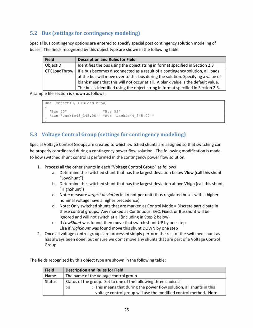
5.2 Bus (settings for contingency modeling)
Special bus contingency options are entered to specify special post contingency solution modeling of buses. The fields recognized by this object type are shown in the following table.
Field Description and Rules for Field ObjectID Identifies the bus using the object string in format specified in Section 2.3 CTGLoadThrow If a bus becomes disconnected as a result of a contingency solution, all loads
at the bus will move over to this bus during the solution. Specifying a value of blank means that this will not occur at all. A blank value is the default value. The bus is identified using the object string in format specified in Section 2.3.
A sample file section is shown as follows:
Bus (ObjectID, CTGLoadThrow) { "Bus 50" "Bus 52" "Bus 'Jackie43_345.00'" "Bus 'Jackie44_345.00'" }
5.3 Voltage Control Group (settings for contingency modeling)
Special Voltage Control Groups are created to which switched shunts are assigned so that switching can be properly coordinated during a contingency power flow solution. The following modification is made to how switched shunt control is performed in the contingency power flow solution.
1. Process all the other shunts in each “Voltage Control Group” as follows a. Determine the switched shunt that has the largest deviation below Vlow (call this shunt
“LowShunt”) b. Determine the switched shunt that has the largest deviation above Vhigh (call this shunt
“HighShunt”) c. Note: measure largest deviation in kV not per unit (thus regulated buses with a higher
nominal voltage have a higher precedence) d. Note: Only switched shunts that are marked as Control Mode = Discrete participate in
these control groups. Any marked as Continuous, SVC, Fixed, or BusShunt will be ignored and will not switch at all (including in Step 2 below)
e. If LowShunt was found, then move that switch shunt UP by one step Else if HighShunt was found move this shunt DOWN by one step
2. Once all voltage control groups are processed simply perform the rest of the switched shunt as has always been done, but ensure we don’t move any shunts that are part of a Voltage Control Group.
The fields recognized by this object type are shown in the following table:
Field Description and Rules for Field Name The name of the voltage control group Status Status of the group. Set to one of the following three choices:
ON : This means that during the power flow solution, all shunts in this voltage control group will use the modified control method. Note

26
that shunts will still be disabled if the global option for disabling switched shunt control is chosen.
OFF : This means the shunts in the voltage control group default back to their individual settings so the solution behaves as though the voltage control group does not exit.
FORCEON : This works the same as ON, but will ignore the global option for disabling the switched shunt control.
A sample file section is shown as follows:
VoltageControlGroup (Name, Status) { "My Group Name 1" "ON" "My Group Name 2" "OFF" "My Group Name 3" "FORCEON" }
5.4 Shunt (settings for contingency modeling)
Special switched shunt contingency options are entered to specify groups of switched shunts that will coordinate their switching during a power flow solution. The fields recognized by this object type are shown in the following table:
Field Description and Rules for Field ObjectID Identifies the shunt using the object string in format of Section 2.3 VoltageControlGroup Name of the Voltage Control Group to which the shunt belongs.
A sample file section is shown as follows:
Shunt (ObjectID, VoltageControlGroup) { "Shunt 'Texan_69.0' '1'" "My Group Name 1" "Shunt 'Viking_345' '1'" "My Group Name 1" "Shunt 'Viking_345' '2'" "My Group Name 2" "Shunt 'Jet_69.0' '1'" "My Group Name 2" "Shunt 77 '1'" "My Group Name 3" }
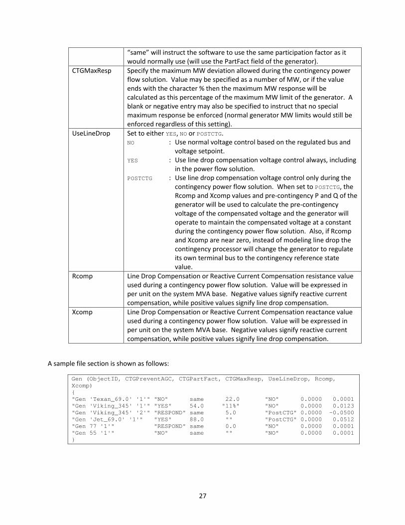
5.5 Gen (settings for contingency modeling)
Special generator contingency options are entered to specify post contingency solution modeling of generators. The fields recognized by this object type are shown in the following table:
Field Description and Rules for Field ObjectID Identifies the generator using the object string in format of Section 2.3 CTGPreventAGC Set to one of the following three choices:
Respond : Generator MW output will respond to changes during the contingency power flow solution
YES : Generator MW output will not change NO : Setting specified in the case will be used (the AGC field)
CTGPartFact Specifies a participation factor that will be used to determine the amount of response from a generator relative to other generators. Specifying a value of
27
“same” will instruct the software to use the same participation factor as it would normally use (will use the PartFact field of the generator).
CTGMaxResp Specify the maximum MW deviation allowed during the contingency power flow solution. Value may be specified as a number of MW, or if the value ends with the character % then the maximum MW response will be calculated as this percentage of the maximum MW limit of the generator. A blank or negative entry may also be specified to instruct that no special maximum response be enforced (normal generator MW limits would still be enforced regardless of this setting).
UseLineDrop Set to either YES, NO or POSTCTG. NO : Use normal voltage control based on the regulated bus and
voltage setpoint. YES : Use line drop compensation voltage control always, including
in the power flow solution. POSTCTG : Use line drop compensation voltage control only during the
contingency power flow solution. When set to POSTCTG, the Rcomp and Xcomp values and pre-contingency P and Q of the generator will be used to calculate the pre-contingency voltage of the compensated voltage and the generator will operate to maintain the compensated voltage at a constant during the contingency power flow solution. Also, if Rcomp and Xcomp are near zero, instead of modeling line drop the contingency processor will change the generator to regulate its own terminal bus to the contingency reference state value.
Rcomp Line Drop Compensation or Reactive Current Compensation resistance value used during a contingency power flow solution. Value will be expressed in per unit on the system MVA base. Negative values signify reactive current compensation, while positive values signify line drop compensation.
Xcomp Line Drop Compensation or Reactive Current Compensation reactance value used during a contingency power flow solution. Value will be expressed in per unit on the system MVA base. Negative values signify reactive current compensation, while positive values signify line drop compensation.
A sample file section is shown as follows:
Gen (ObjectID, CTGPreventAGC, CTGPartFact, CTGMaxResp, UseLineDrop, Rcomp, Xcomp) { "Gen 'Texan_69.0' '1'" "NO" same 22.0 "NO" 0.0000 0.0001 "Gen 'Viking_345' '1'" "YES" 54.0 "11%" "NO" 0.0000 0.0123 "Gen 'Viking_345' '2'" "RESPOND" same 5.0 "PostCTG" 0.0000 -0.0500 "Gen 'Jet_69.0' '1'" "YES" 88.0 "" "PostCTG" 0.0000 0.0512 "Gen 77 '1'" "RESPOND" same 0.0 "NO" 0.0000 0.0001 "Gen 55 '1'" "NO" same "" "NO" 0.0000 0.0001 }

28
5.6 Sim_Solution_Options_Value
There is set of power flow solution options that impact the contingency solutions in a contingency processor. Each power flow solution option (Sim_Solution_Options_Value) has a unique string identifier and then a particular set of potential values associated with them. The field names for the object are simply Option and Value. The following table shows a list of the string identifiers for each option and a description of what the value should contain. These options may be overridden by contingency analysis options as well, which are discussed in Section 5.7. Any file parser should simply ignore any options that the tool does not recognize, need, or use. It should simply provide warning messages that the option is not recognized, needed or used as appropriate.
Option Value DynAssignSlack Set to YES to allow the contingency power flow solution to dynamically
assign new slack buses if new electric islands are created as a result of switching in the contingency. Set to NO to not allow this (new islands will be treated as dead).
PUConvergenceTol Floating point value of the convergence tolerance. Units are in per unit. Thus to express a 0.02 MVA tolerance, if SBase = 100, then enter 0.0002.
MaxItr Integer for maximum inner power flow loop calculation iterations MinVoltILoad Floating point for minimum PU Voltage for Constant Current Loads MinVoltSLoad Minimum PU Voltage for Constant Current Loads Minimum PU Voltage
for Constant Power Loads EnforceGenMWLimits Set to YES to enforce generator MW limits or NO to not enforce MaxItrVoltLoop Integer for maximum voltage control loop calculation iterations
(generator Mvar checking, tap control, shunt control, etc.) LTCTapBalance Set to YES to force parallel transformer taps to balance their tap ratios or
NO to leave them alone. ChkPhaseShifters Set to YES to allow phase shifter control or NO to prevent it. ChkSVCs Set to YES to allow SVC switched shunt control or NO to prevent it. ChkShunts Set to YES to allow switched shunt control or NO to prevent it. ChkTaps Set to YES to allow transformer tap ratio control or NO to prevent it. ChkVarImmediately Set to YES to check generator Mvar limits after each inner power flow
loop iteration. MinLTCSense Specify a floating point value representing the minimum transformer tap
sensitivity (derivative of control voltage with respect to change the tap ratio). Transformers with a sensitivity below this value will not be moved.
ModelPSDiscrete Set to YES to model phase shifters as a discrete control or NO to allow the phase shift angle to vary continuously between the minimum and maximum angle.
PreventOscillations Set to YES to prevent controller oscillations. ShuntInner Set to YES to model continuous switch shunts as PV buses in the inner
power flow loop.
A sample file section is shown as follows:

29
Sim_Solution_Options_Value (VariableName,Value) { "DynAssignSlack" "YES" "DisableOptMult" "NO" "MaxItr" "100" "MinVoltILoad" "0" "MinVoltSLoad" "0" "AGCTolerance" "0.05" "EnforceGenMWLimits" "YES" "LTCTapBalance" "YES" "ChkPhaseShifters" "YES" "ChkSVCs" "YES" "ChkShunts" "YES" "ChkTaps" "YES" "DisableGenMVRCheck" "NO" "ChkVarImmediately" "NO" "MaxItrVoltLoop" "20" "MinLTCSense" "0.01" "ModelPSDiscrete" "NO" "PreventOscillations" "YES" "ShuntInner" "YES" }

30
5.7 CTG_Options_Value
Each contingency solution option has a unique string identifier and then a particular set of potential values associated with them. The field names for the object are simply Option and Value. The following table shows a list of the string identifiers for each option and a description of what the value should contain. Any file parser should simply ignore any options that the tool does not recognize, need, or use. It should simply provide warning messages that the option is not recognized, needed or used as appropriate.
Option Value TSModelsTrip Comma-delimited list of transient stability model types that will act or trip
in the contingency processor. See Section 5.7.1 for more details. TSModelsMonitor Comma-delimited list of transient stability model types that will only be
monitored in the contingency processor. See Section 5.7.1 for details. TSModelMaxDelay A number of seconds. See Section 5.7.1 for more details. DisableGenDropOverlap There are particular ContingencyElement actions that open generators
within an injection group in merit order. If more than one contingency element such as this is implemented in the same contingency, then there may be overlap in the list of generators between the multiple injection groups. Set this value to YES to treat these actions independently. Set this value to NO to count any generation change in the first injection group to count toward the total change desired in subsequent injection groups.
MakeUpPower Set to one of the following three choices Area Part Factors
: Specifies that changes in injection caused by the contingency should be made up by the areas in the case in proportion to the Area records CTGMakupGen factors (see Section 5.1). Within each area, the individual participation factors of generators on AGC determine how much power will come from each generator.
Gen Part Factors : Specifies that changes in injection caused by the
contingency should be made up by the all generators in the case in proportion to the individual participation factors of generators on AGC.
Same as Power Flow
: Specifies that changes in injection caused by the contingency should be made up in the same way that the regular power flow solution is configured to solve. This option is not recommended.
AGCTolerance Specify the MW control loop solution tolerance in MWs
All of the Sim_Solution_Options_Value options presented in Section 5.6 may be overridden by a contingency analysis specific option. Within the CTG_Options_Value records any of these values may be specified as Default which will indicate that the option simply defaults to the global power flow solution options shown in Section 5.6.

31
The following options are also available for the CTG_Options_Value object and represent advanced limit monitoring settings that will ignore or report special limit violations based on a change monitored value from the contingency reference case.
Option Value MonDiscBus Set to YES to report as a violation any bus that becomes disconnected as a
result of a contingency. Set to NO to not do this. VoltChangePercent Set to YES to treat following change values as a percentage change from the
contingency reference case. Thus if AlwaysLowVoltDec = 0.05 interpret this as a 5% decrease from the reference case. Set to NO to treat voltage changes as a per unit change, thus 0.05 means a 0.05 per unit change.
The following 5 options allow the specification of limit violations that should always be reported based on a change in value from the contingency reference case, even if the value does not exceed the limits AlwaysReport Set to YES to enable the following 4 options for always reporting violations
based on a change in value from the contingency reference case. Set to NO to ignore these 4 options.
AlwaysBranchInc Specify a percentage. This is the minimum change in a branch flow in percentage (of the post-contingency rating) that the loading on a branch must increase so that the branch gets reported as a violation
AlwaysHighVoltInc Specify a per unit voltage change (interpretation is determined by field VoltChangePercent). This is the minimum amount that a bus voltage must increase for a bus high voltage violation to be reported
AlwaysInterfaceInc Specify a percentage value. This is the minimum change in interface flow in percentage (of the post-contingency rating) that the loading on an interface must increase so that the interface gets reported as a violation.
AlwaysLowVoltDec Specify a per unit voltage change (interpretation is determined by field VoltChangePercent). This is the minimum amount that a bus voltage must decrease for a bus low voltage violation to be reported.
The following 5 options allow the specification of limit violations that should never be reported based on a change in value from the contingency reference case, even if the value does exceed the limits NeverReport Set to YES to enable the following 4 options for never reporting violations
based on a change in value from the contingency reference case. Set to NO to ignore these 4 options.
NeverBranchInc Specify a percentage value. This is the minimum change in percentage (of the post-contingency rating) that the loading on a line/transformer must increase before the line/transformer gets reported as a violation.
NeverHighVoltInc Specify a per unit voltage change (interpretation is determined by field VoltChangePercent). This is the minimum change in a bus voltage that must occur for bus high voltage violation to be reported.
NeverInterfaceInc Specify a percentage value. This is the minimum change in percentage (of the post-contingency rating) that the loading on an interface must increase before the interface gets reported as a violation.
NeverLowVoltDec Specify a per unit voltage change (interpretation is determined by field VoltChangePercent). This is the minimum change in a bus voltage that must occur for a bus low voltage violation to be reported.
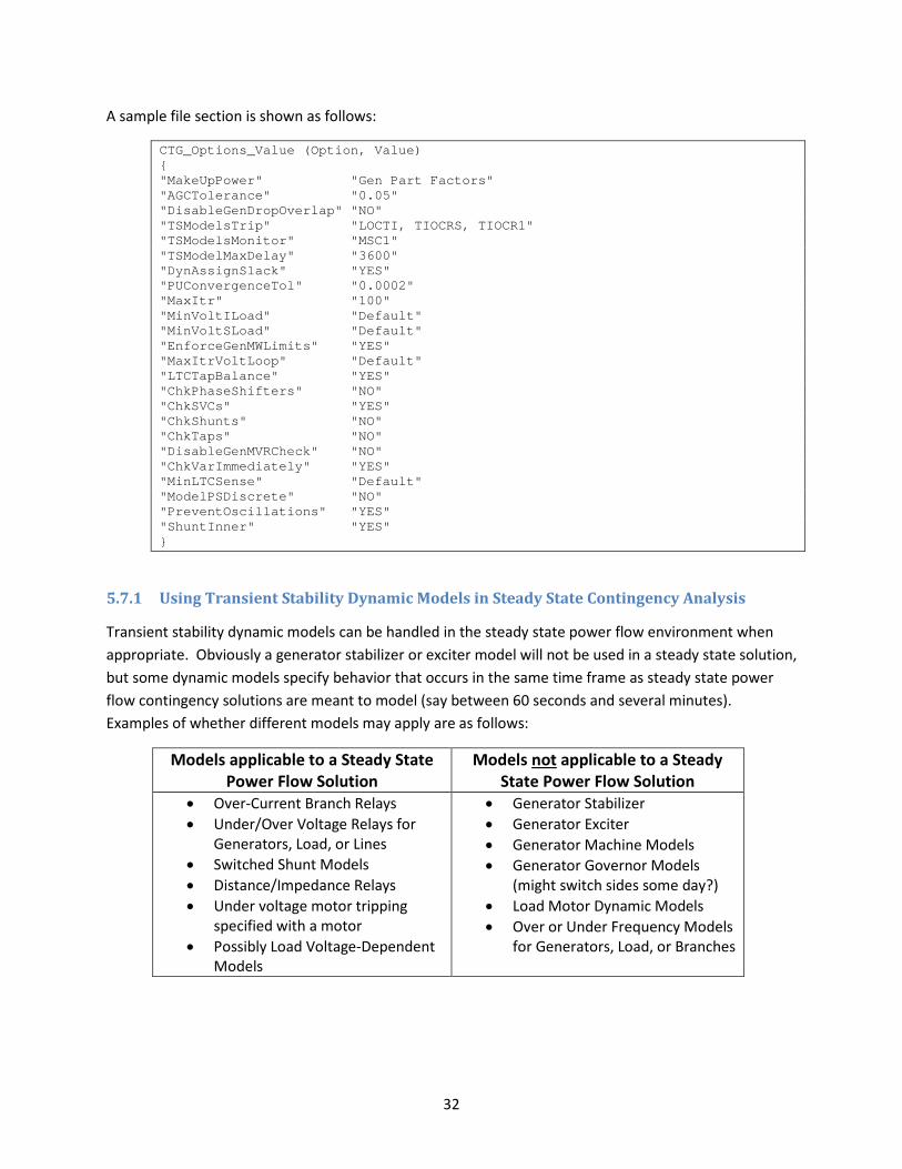
32
A sample file section is shown as follows:
CTG_Options_Value (Option, Value) { "MakeUpPower" "Gen Part Factors" "AGCTolerance" "0.05" "DisableGenDropOverlap" "NO" "TSModelsTrip" "LOCTI, TIOCRS, TIOCR1" "TSModelsMonitor" "MSC1" "TSModelMaxDelay" "3600" "DynAssignSlack" "YES" "PUConvergenceTol" "0.0002" "MaxItr" "100" "MinVoltILoad" "Default" "MinVoltSLoad" "Default" "EnforceGenMWLimits" "YES" "MaxItrVoltLoop" "Default" "LTCTapBalance" "YES" "ChkPhaseShifters" "NO" "ChkSVCs" "YES" "ChkShunts" "NO" "ChkTaps" "NO" "DisableGenMVRCheck" "NO" "ChkVarImmediately" "YES" "MinLTCSense" "Default" "ModelPSDiscrete" "NO" "PreventOscillations" "YES" "ShuntInner" "YES" }
5.7.1 Using Transient Stability Dynamic Models in Steady State Contingency Analysis
Transient stability dynamic models can be handled in the steady state power flow environment when appropriate. Obviously a generator stabilizer or exciter model will not be used in a steady state solution, but some dynamic models specify behavior that occurs in the same time frame as steady state power flow contingency solutions are meant to model (say between 60 seconds and several minutes). Examples of whether different models may apply are as follows:
Models applicable to a Steady State Power Flow Solution
Models not applicable to a Steady State Power Flow Solution
• Over-Current Branch Relays • Under/Over Voltage Relays for
Generators, Load, or Lines • Switched Shunt Models • Distance/Impedance Relays • Under voltage motor tripping
specified with a motor • Possibly Load Voltage-Dependent
Models
• Generator Stabilizer • Generator Exciter • Generator Machine Models • Generator Governor Models
(might switch sides some day?) • Load Motor Dynamic Models • Over or Under Frequency Models
for Generators, Load, or Branches
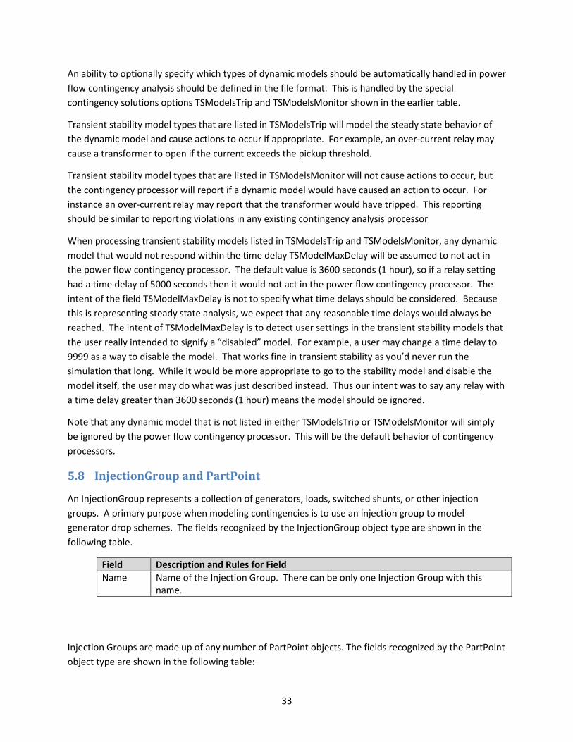
33
An ability to optionally specify which types of dynamic models should be automatically handled in power flow contingency analysis should be defined in the file format. This is handled by the special contingency solutions options TSModelsTrip and TSModelsMonitor shown in the earlier table.
Transient stability model types that are listed in TSModelsTrip will model the steady state behavior of the dynamic model and cause actions to occur if appropriate. For example, an over-current relay may cause a transformer to open if the current exceeds the pickup threshold.
Transient stability model types that are listed in TSModelsMonitor will not cause actions to occur, but the contingency processor will report if a dynamic model would have caused an action to occur. For instance an over-current relay may report that the transformer would have tripped. This reporting should be similar to reporting violations in any existing contingency analysis processor
When processing transient stability models listed in TSModelsTrip and TSModelsMonitor, any dynamic model that would not respond within the time delay TSModelMaxDelay will be assumed to not act in the power flow contingency processor. The default value is 3600 seconds (1 hour), so if a relay setting had a time delay of 5000 seconds then it would not act in the power flow contingency processor. The intent of the field TSModelMaxDelay is not to specify what time delays should be considered. Because this is representing steady state analysis, we expect that any reasonable time delays would always be reached. The intent of TSModelMaxDelay is to detect user settings in the transient stability models that the user really intended to signify a “disabled” model. For example, a user may change a time delay to 9999 as a way to disable the model. That works fine in transient stability as you’d never run the simulation that long. While it would be more appropriate to go to the stability model and disable the model itself, the user may do what was just described instead. Thus our intent was to say any relay with a time delay greater than 3600 seconds (1 hour) means the model should be ignored.
Note that any dynamic model that is not listed in either TSModelsTrip or TSModelsMonitor will simply be ignored by the power flow contingency processor. This will be the default behavior of contingency processors.
5.8 InjectionGroup and PartPoint
An InjectionGroup represents a collection of generators, loads, switched shunts, or other injection groups. A primary purpose when modeling contingencies is to use an injection group to model generator drop schemes. The fields recognized by the InjectionGroup object type are shown in the following table.
Field Description and Rules for Field Name Name of the Injection Group. There can be only one Injection Group with this
name.
Injection Groups are made up of any number of PartPoint objects. The fields recognized by the PartPoint object type are shown in the following table:
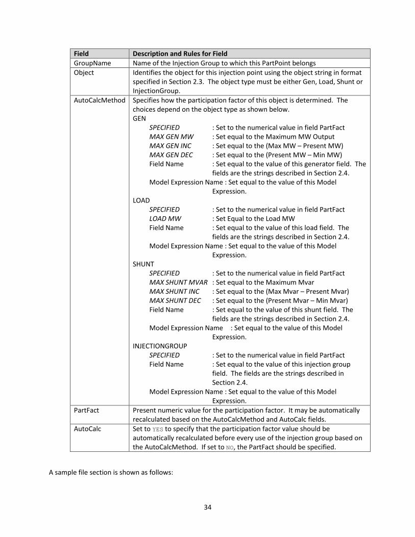
34
Field Description and Rules for Field GroupName Name of the Injection Group to which this PartPoint belongs Object Identifies the object for this injection point using the object string in format
specified in Section 2.3. The object type must be either Gen, Load, Shunt or InjectionGroup.
AutoCalcMethod Specifies how the participation factor of this object is determined. The choices depend on the object type as shown below. GEN
SPECIFIED : Set to the numerical value in field PartFact MAX GEN MW : Set equal to the Maximum MW Output MAX GEN INC : Set equal to the (Max MW – Present MW) MAX GEN DEC : Set equal to the (Present MW – Min MW) Field Name : Set equal to the value of this generator field. The
fields are the strings described in Section 2.4. Model Expression Name : Set equal to the value of this Model
Expression. LOAD
SPECIFIED : Set to the numerical value in field PartFact LOAD MW : Set Equal to the Load MW Field Name : Set equal to the value of this load field. The
fields are the strings described in Section 2.4. Model Expression Name : Set equal to the value of this Model
Expression. SHUNT
SPECIFIED : Set to the numerical value in field PartFact MAX SHUNT MVAR : Set equal to the Maximum Mvar MAX SHUNT INC : Set equal to the (Max Mvar – Present Mvar) MAX SHUNT DEC : Set equal to the (Present Mvar – Min Mvar) Field Name : Set equal to the value of this shunt field. The
fields are the strings described in Section 2.4. Model Expression Name : Set equal to the value of this Model
Expression. INJECTIONGROUP
SPECIFIED : Set to the numerical value in field PartFact Field Name : Set equal to the value of this injection group
field. The fields are the strings described in Section 2.4.
Model Expression Name : Set equal to the value of this Model Expression.
PartFact Present numeric value for the participation factor. It may be automatically recalculated based on the AutoCalcMethod and AutoCalc fields.
AutoCalc Set to YES to specify that the participation factor value should be automatically recalculated before every use of the injection group based on the AutoCalcMethod. If set to NO, the PartFact should be specified.
A sample file section is shown as follows:
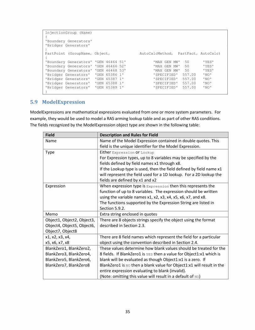
35
InjectionGroup (Name) { "Boundary Generators" "Bridger Generators" } PartPoint (GroupName, Object, AutoCalcMethod, PartFact, AutoCalc) { "Boundary Generators" "GEN 46464 51" "MAX GEN MW" 50 "YES" "Boundary Generators" "GEN 46466 52" "MAX GEN MW" 50 "YES" "Boundary Generators" "GEN 46468 53" "MAX GEN MW" 50 "YES" "Bridger Generators" "GEN 65386 1" "SPECIFIED" 557.00 "NO" "Bridger Generators" "GEN 65387 1" "SPECIFIED" 557.00 "NO" "Bridger Generators" "GEN 65388 1" "SPECIFIED" 557.00 "NO" "Bridger Generators" "GEN 65389 1" "SPECIFIED" 557.00 "NO" }
5.9 ModelExpression
ModelExpressions are mathematical expressions evaluated from one or more system parameters. For example, they would be used to model a RAS arming lookup table and as part of other RAS conditions. The fields recognized by the ModelExpression object type are shown in the following table:
Field Description and Rules for Field Name Name of the Model Expression contained in double quotes. This
field is the unique identifier for the Model Expression. Type Either Expression or Lookup
For Expression types, up to 8 variables may be specified by the fields defined by field names x1 through x8. If the Lookup type is used, then the field defined by field name x1 will represent the field used for a 1D lookup. For a 2D lookup the fields are defined by x1 and x2
Expression When expression type is Expression then this represents the function of up to 8 variables. The expression should be written using the variable names x1, x2, x3, x4, x5, x6, x7, and x8. The functions supported by the Expression String are listed in Section 5.9.2.
Memo Extra string enclosed in quotes Object1, Object2, Object3, Object4, Object5, Object6, Object7, Object8
There are 8 objects strings specify the object using the format described in Section 2.3.
x1, x2, x3, x4, x5, x6, x7, x8
There are 8 field names which represent the field for a particular object using the convention described in Section 2.4.
BlankZero1, BlankZero2, BlankZero3, BlankZero4, BlankZero5, BlankZero6, BlankZero7, BlankZero8
These values determine how blank values should be treated for the 8 fields. If BlankZero1 is YES then a value for Object1:x1 which is blank will be evaluated as though Object1:x1 is a zero. If BlankZero1 is NO then a blank value for Object1:x1 will result in the entire expression evaluating to blank (invalid). (Note: omitting this value will result in a default of NO)

36
5.9.1 Lookup Tables
Lookup tables allow returning a value from a lookup based on the value of the specified x1 and/or x2 fields instead of specifying a mathematical expression.
The ModelExpression requires a special feature in the file format to handle the specification of a lookup table. This is done by using special tags to surround the lookup table specification. The lookup table is initiated by the tag <SUBDATA LookupTable> and then terminated by the tag </SUBDATA> . The formatting inside the tags is described as follows.
A lookup table represents either one or two dimensional tables (1D or 2D). This is determined by reading the first string in the first row inside the SUBDATA section. If the first text row inside the SUBDATA section starts with the string “x1x2”, this signifies that this represents a two dimensional lookup table, otherwise it signifies a one-dimensional lookup table.
For 2D lookup tables, from that first string it will read the remainder of the numerical entries in the first row as x2 lookup points, the first column in the remainder of the rows as the x1 lookup points, and the subsequent entries as the various result values for the lookups for respective values of x1 and x2. The lookup value that is returned from the lookup is the intersection of the present values of fields x1 and x2 in the table where both values are less than or equal to the lookup points.
For 1D tables the remainder of the first line of the SUBDATA section is ignored and in the following rows the first entry represents x1 lookup points while the second value represents the lookup value. The value that is returned from the table is the lookup value where the present value of x1 is less than or equal to the lookup point.
A sample file section is shown as follows:
ModelExpression (Name, Type, Expression, Memo, Object1, x1, Object2, x2) { "Gen Drop Table 1" "Lookup" "" "Memo Str" "Interface 'My Int Name1'" "MW" "" "" <SUBDATA Lookup> // because it does not start with the string x1x2 this will // represent a one dimensional lookup table x1 Value // first row is ignored 2700 0 2900 500 3200 1100 4400 1700 4800 1700 </SUBDATA> "Gen Drop Table 2" "Lookup" "" "Memo String Here" "Interface 'My Int Name1'" "MW" "Interface 'My Int Name2'" "MW" <SUBDATA Lookup> // because this starts with x1x2 this represent a two dimensional // lookup table. The first row represents lookup values for x2 // The first column represents lookup values for x1. x1x2 1500 1600 1800 2000 2200 2400 2600 2800 3000 3100 1900 0 0 0 0 0 0 0 0 0 0 2000 0 0 0 0 0 0 0 0 0 600 2200 0 0 0 0 0 0 0 0 600 600 2400 0 0 0 0 0 0 0 600 900 900 2600 0 0 0 0 0 0 600 900 900 900 2800 0 0 0 0 0 600 900 900 900 1200
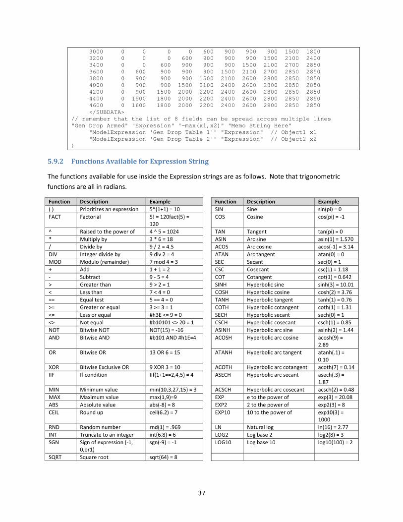
37
3000 0 0 0 0 600 900 900 900 1500 1800 3200 0 0 0 600 900 900 900 1500 2100 2400 3400 0 0 600 900 900 900 1500 2100 2700 2850 3600 0 600 900 900 900 1500 2100 2700 2850 2850 3800 0 900 900 900 1500 2100 2600 2800 2850 2850 4000 0 900 900 1500 2100 2400 2600 2800 2850 2850 4200 0 900 1500 2000 2200 2400 2600 2800 2850 2850 4400 0 1500 1800 2000 2200 2400 2600 2800 2850 2850 4600 0 1600 1800 2000 2200 2400 2600 2800 2850 2850 </SUBDATA> // remember that the list of 8 fields can be spread across multiple lines "Gen Drop Armed" "Expression" "-max(x1,x2)" "Memo String Here" "ModelExpression 'Gen Drop Table 1'" "Expression" // Object1 x1 "ModelExpression 'Gen Drop Table 2'" "Expression" // Object2 x2 }
5.9.2 Functions Available for Expression String
The functions available for use inside the Expression strings are as follows. Note that trigonometric functions are all in radians.
Function Description Example Function Description Example ( ) Prioritizes an expression 5*(1+1) = 10 SIN Sine sin(pi) = 0 FACT Factorial 5! = 120fact(5) =
120 COS Cosine cos(pi) = -1
^ Raised to the power of 4 ^ 5 = 1024 TAN Tangent tan(pi) = 0 * Multiply by 3 * 6 = 18 ASIN Arc sine asin(1) = 1.570 / Divide by 9 / 2 = 4.5 ACOS Arc cosine acos(-1) = 3.14 DIV Integer divide by 9 div 2 = 4 ATAN Arc tangent atan(0) = 0 MOD Modulo (remainder) 7 mod 4 = 3 SEC Secant sec(0) = 1 + Add 1 + 1 = 2 CSC Cosecant csc(1) = 1.18 - Subtract 9 - 5 = 4 COT Cotangent cot(1) = 0.642 > Greater than 9 > 2 = 1 SINH Hyperbolic sine sinh(3) = 10.01 < Less than 7 < 4 = 0 COSH Hyperbolic cosine cosh(2) = 3.76 == Equal test 5 == 4 = 0 TANH Hyperbolic tangent tanh(1) = 0.76 >= Greater or equal 3 >= 3 = 1 COTH Hyperbolic cotangent coth(1) = 1.31 <= Less or equal #h3E <= 9 = 0 SECH Hyperbolic secant sech(0) = 1 <> Not equal #b10101 <> 20 = 1 CSCH Hyperbolic cosecant csch(1) = 0.85 NOT Bitwise NOT NOT(15) = -16 ASINH Hyperbolic arc sine asinh(2) = 1.44 AND Bitwise AND #b101 AND #h1E=4 ACOSH Hyperbolic arc cosine acosh(9) =
2.89 OR Bitwise OR 13 OR 6 = 15 ATANH Hyperbolic arc tangent atanh(.1) =
0.10 XOR Bitwise Exclusive OR 9 XOR 3 = 10 ACOTH Hyperbolic arc cotangent acoth(7) = 0.14 IIF If condition IIf(1+1==2,4,5) = 4 ASECH Hyperbolic arc secant asech(.3) =
1.87 MIN Minimum value min(10,3,27,15) = 3 ACSCH Hyperbolic arc cosecant acsch(2) = 0.48 MAX Maximum value max(1,9)=9 EXP e to the power of exp(3) = 20.08 ABS Absolute value abs(-8) = 8 EXP2 2 to the power of exp2(3) = 8 CEIL Round up ceil(6.2) = 7 EXP10 10 to the power of exp10(3) =
1000 RND Random number rnd(1) = .969 LN Natural log ln(16) = 2.77 INT Truncate to an integer int(6.8) = 6 LOG2 Log base 2 log2(8) = 3 SGN Sign of expression (-1,
0,or1) sgn(-9) = -1 LOG10 Log base 10 log10(100) = 2
SQRT Square root sqrt(64) = 8

38
5.10 ModelCondition and ModelConditionCondition
ModelConditions are used to specify the conditions under which a contingency or RAS action should be performed or armed.
The fields recognized by the ModelCondition object type are shown in the following table.
Field Description and Rules for Field Name Name of the Model Condition contained in double quotes. Note: Names
must be unique across all other ModelFilters and ModelConditions. Object The object to which the condition applies. Specify the object using the
format described in Section 2.3. FilterObjectType Most commonly, the list of ModelConditionConditions that apply to this
ModelCondition are evaluated against the object referred to by Object. However, it is also possible to specify a different object type for the ModelConditionConditions. For example a BUS may be specified in the Object, but FilterObjectType may be set to BRANCH. If this is done then the Model Condition will evaluate to TRUE if any BRANCH connected to the bus meets the logic of the ModelConditionConditions. These inherent inter-object relationships are available for the object types enumerated in Section 2.2
FilterLogic Logic to apply to the list of comparisons (AND, OR, NAND, NOR) EvaluateInRef Specify as YES to cause the model condition to evaluate itself in the
reference case and never reevaluate during a contingency solution DisableIfTrueInRef specify as YES to disable this model condition for the entire contingency
run if it evaluated TRUE in the reference (this is used so that a model condition can be created that checks the status of a branch being opened, but you want to restrict it to triggering an event only when the branch is opened as a RESULT of the contingency). (See Model Filter explanation in Section 5.11.1).
Memo Extra string enclosed in quotes ModelConditions are made up of any number of ModelConditionCondition objects (apologies for the object type name, but nothing else makes sense). The fields recognized by the ModelConditionCondition object type are shown in the following table.
Field Description and Rules for Field ModelCondition Name of the ModelCondition to which this applies CondNum Number specifying the number of the condition. Omitting this value, or
specifying a value of zero will cause this to automatically add the condition to the existing ModelCondition. Otherwise by specifying a number you can edit existing conditions.
ObjectField A field associated with the object to which this model condition applies. A list of fields is shown in Section 2.4. In addition to these fields, you may also specify the string "_UseAnotherFilter" to signify that this condition refers to another Filter. This will be important for the creation of more complex nested filter definitions as described in Section 3.2.
ConditionType The comparison operator applied to the ObjectField and the Value and OtherValue entries. There are many choices as follows:

39
= equal (should not use for numbers) <> not equal > greater than < less than >= greater than or equal <= less than or equal Integer comparisons inrange enter a string as the Value of the form "2-5, 70-90” notinrange enter a string as the Value. Opposite of inrange String Comparisons contains returns whether string contains a particular substring notcontains opposite of contains startswith returns whether a string starts with a string notstartswith opposite of startswith Two value comparisons about specify two values. Return whether the field is within
the OtherValue (tolerance) of the Value notabout specify two values. Opposite of about between specify two values field is between notbetween specify two values field is not between _UseAnotherFilter comparisons Meets returns whether another filter’s conditions are met Not Meets returns whether another filter’s conditions are not met
Value
Value or Field or Expression. The entry specifies the value to which the field is compared. This may be done in three ways Value : 1.459 or a String Field : start with the tag <Field> and then follow with a string
using the format as the ObjectField string Model Expression : start with the tag <Expression> and then follow the
name of the Model Expression OtherValue This entry’s format is the same as the previous entry. It is only used for the
between, notbetween, about, and notabout Condition Types Absolute Set to YES to take the absolute value of the ObjectField begin compared
A sample file section is shown as follows:
ModelCondition (Name, Object, FilterObjectType, FilterLogic, EvaluateInRef, DisableIfTrueInRef, Memo) { "2-11 Line (Open)" "Branch 2 11 1" "Branch" "AND" "YES" "YES" "check 2-11" "3-44 Line (Open)" "Branch 3 44 1" "Branch" "AND" "YES" "YES" "check 3-44" "Interface Bobby High" "Interface 'Bobby'" "Interface" "AND" "NO" "NO" "checkbobby" "Bus Jackie Low" "Bus 'Jackie_500.00'" "Bus" "AND" "NO" "NO" "checkJackie" "Sample Field and Exp" "Gen 'Jackie_34.50' '1'" "Gen" "AND" "NO" "NO" "checkJackie" } ModelConditionCondition (ModelCondition, CondNum, ObjectField, ConditionType, Value, OtherValue, Absolute) { "2-11 Line (Open)" "1" "DerivedOnline" "=" "Closed" "" "NO"
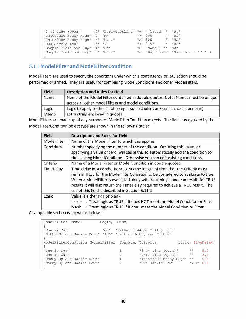
40
"3-44 Line (Open)" "2" "DerivedOnline" "=" "Closed" "" "NO" "Interface Bobby High" "3" "MW" ">" 500 "" "NO" "Interface Bobby High" "4" "Mvar" ">" 100 "" "NO" "Bus Jackie Low" "5" "V" "<" 0.95 "" "NO" "Sample Field and Exp" "6" "MW" ">" "MWMax" "" "NO" "Sample Field and Exp" "7" "Mvar" ">" "Expression 'Mvar Lim'" "" "NO" }
5.11 ModelFilter and ModelFilterCondition
ModelFilters are used to specify the conditions under which a contingency or RAS action should be performed or armed. They are useful for combining ModelConditions and other ModelFilters.
Field Description and Rules for Field Name Name of the Model Filter contained in double quotes. Note: Names must be unique
across all other model filters and model conditions. Logic Logic to apply to the list of comparisons (choices are AND, OR, NAND, and NOR) Memo Extra string enclosed in quotes
ModelFilters are made up of any number of ModelFilterCondition objects. The fields recognized by the ModelFilterCondition object type are shown in the following table:
Field Description and Rules for Field ModelFilter Name of the Model Filter to which this applies CondNum Number specifying the number of the condition. Omitting this value, or
specifying a value of zero, will cause this to automatically add the condition to the existing ModelCondition. Otherwise you can edit existing conditions.
Criteria Name of a Model Filter or Model Condition in double quotes. TimeDelay Time delay in seconds. Represents the length of time that the Criteria must
remain TRUE for the ModelFilterCondition to be considered to evaluate to true. When a ModelFilter is evaluated along with returning a boolean result, for TRUE results it will also return the TimeDelay required to achieve a TRUE result. The use of this field is described in Section 5.11.2
Logic Value is either NOT or blank "NOT" : Treat logic as TRUE if it does NOT meet the Model Condition or Filter blank : Treat logic as TRUE if it does meet the Model Condition or Filter
A sample file section is shown as follows:
ModelFilter (Name, Logic, Memo) { "One is Out" "OR" "Either 3-44 or 2-11 go out" "Bobby Up and Jackie Down" "AND" "test on Bobby and Jackie" } ModelFilterCondition (ModelFilter, CondNum, Criteria, Logic, TimeDelay) { "One is Out" 1 "3-44 Line (Open)" "" 5.0 "One is Out" 2 "2-11 Line (Open)" "" 3.0 "Bobby Up and Jackie Down" 1 "Interface Bobby High" "" 0.0 "Bobby Up and Jackie Down" 2 "Bus Jackie Low" "NOT" 0.0 }

41
5.11.1 Handling DisableIfTrueInRef for ModelFilterConditions
When the DisableIfTrueInRef field is set to YES for a ModelCondition that is used in a ModelFilterCondition and the condition is true in the contingency reference case, that ModelCondition will be ignored when evaluated as part of the ModelFilter. This means it will be evaluated to neither true nor false but instead will be treated as if it doesn’t exist in the ModelFilter. If all ModelFilterConditions are ignored for the ModelFilter, the entire ModelFilter will be ignored.
For example, if a ModelFilter contains three conditions for three different branches being opened: Line A, Line B, AND Line C. Also, the ModelFilter is configured to be true if ALL of the branches are opened. If all three conditions are defined with DisableIfTrueInRef set to YES and Line A is out in the contingency reference state, the ModelFilter will be evaluated by checking only Line B AND Line C because the Line A condition has been ignored. If all three lines are out in the contingency reference case, the ModelFilter will be treated as if it doesn’t exist and the contingency or RAS action using this ModelFilter will NOT be applied.
5.11.2 Calculated Time Delay of a Model Filter
A TimeDelay must be calculated for any ModelFilter that has ModelFilterConditions that use TimeDelays. The calculated time delay of a ModelFilter will depend on the logic of the gate (OR, AND, NOR, NAND) and the various TimeDelays in the logic diagram. The calculation occurs as follows. Each input ModelFilterCondition will determine its own calculated time delay based on whether the Criteria object is a ModelFilter or a ModelCondtion. We will call that the InputTimeDelay.
Criteria Object InputTimeDelay for the ModelFilterCondition ModelFilter Use the summation of the Calculated Time Delay of the ModelFilter
and the TimeDelay associated with this ModelFilterCondition ModelCondition Directly use TimeDelay associated with this ModelFilterCondition
With these InputTimeDelays, the ModelFilter’s calculated time delay is then determined based on the Logic of the ModelFilter.
Gate Logic Calculated Time Delay AND The maximum InputTimeDelay associated with any of the TRUE
ModelFilterCondition inputs OR The minimum InputTimeDelay associated with any of the TRUE
ModelFilterCondition inputs NAND The minimum InputTimeDelay associated with any of the FALSE
ModelFilterCondition inputs NOR The maximum InputTimeDelay associated with any of the FALSE
ModelFilterCondition inputs To illustrate this, consider the following example logic diagram. The yellow filled boxes represent ModelCondition objects. The orange filled logic gates represent ModelFilter objects. The Blue boxes represent ModelFilterCondition objects. Also note that some of the ModelFilterCondition objects have NOT logic associated with them.

42
That same logic diagram and color code it with green representing TRUE, red representing FALSE, and grey representing disabled . The calculation of time delay is then shown in the figure with blue text.
MFA
MFB
MC1
MC3
MC2
MFCA1 (10 sec)
MFCA2 (30 sec) MFCA3 (50 sec)
MC4 MFCB2 (10 sec)
MC5 MFCB3 (20 sec)
MFCB1 (40 sec)
MFC
MC7
MC6
MFCC1 (5 sec)
MFCC2 (10 sec) MFCC3 (15 sec)
NOT
AND Gate
OR
NAND Gate NOT
W
X (10 sec)
Z
Y (5 sec)
Legend
ModelCondition “W”
ModelFilterCondition “Y” 5 second delay, NOT
ModelFilter
ModelFilterCondition “X” 10 second delay
MFA
MFB
MC1
MC3
MC2
MFCA1 (10 sec)
MFCA2 (30 sec) MFCA3 (50 sec)
MC4 MFCB2 (10 sec)
MC5 MFCB3 (15 sec)
MFCB1 (5 sec)
MFC
MC7
MC6
MFCC1 (8 sec)
MFCC2 (30 sec) MFCC3 (5 sec)
30 sec
23 sec
15 sec
35
15
23
30
5
AND gate, so take the maximum TRUE time delay
Use 35 because it is the summation of the the TimeDelays
10
OR gate, so take the minimum TRUE time delay
NAND gate, so take the minimum FALSE time delay
Use 23 because it is the summation of the TimeDelays
Do not use 5 because that is a TRUE input
MC3 is Disabled MC3 was set to DisableIfTrueInRef

43
5.12 Relationships between objects
The following figure shows the following object types
ModelCondition For one model object, defines a boolean operation across a list of ModelConditionCondition objects
ModelConditionCondition One boolean operation on the object contained in the ModelCondition. This may also point to a ModelExpression object
ModelFilter Defines a boolean operation across a list of ModelFilterCondition objects
ModelFilterCondition Object is contained in a ModelFilter and references either a ModelFilter or ModelCondition
ModelExpression An object describing a mathematical expression or lookup table for the system.
ContingencyElement The ModelCriteria field may reference either a ModelCondition or a ModelFilter The Action field may reference a ModelExpression
5.13 Contingency, ContingencyElement (TSContingency, TSContingencyElement)
Presently there are two separate data structures for storing power flow contingencies as compared to transient stability contingencies.

44
1. Power Flow Contingency (Contingency/ContingencyElement) 2. Transient Stability Contingency (TSContingency/TSContingencyElement)
While separate data structures within the software environment, they are very similar and will be described together with differences noted. The fields recognized by the Contingency (or TSContingency) object type are shown in the following table.
Field Description and Rules for Field Name Unique Name of the Contingency (or TSContingency) Category A comma delimited list of strings representing the contingency categories assigned
to this contingency. For power flow contingencies, these categories will be used in conjunction with the CustomMonitor object described in Section 8.7. For transient stability contingencies, these categories could be used for additional limit monitoring features.
Skip Set to NO and the contingency will be processed by a contingency analysis tool. Set to YES and a contingency processor will ignore this contingency.
Memo Text field that can be used to provide comments attached to the contingency Each Contingency object is made up of any number of ContingencyElement objects, while TSContingency objects are made up of TSContingencyElement objects. The fields recognized by the ContingencyElement and TSContingencyElement object types are shown in the following table (Time is only available for the TSContingencyElement):
Field Description and Rules for Field Contingency Name of the contingency (or TSContingency) to which this element belongs Object Identifies a power system or simulation element specified using the object
string in format specified in Section 2.3. There are minor exceptions to this format described in Section 5.13.1.
Action A string describing this action. There are many options as shown in the following Section 5.13.4
Criteria Name of either a ModelCondition or a ModelFilter that determines the situation under which the action will actually be implemented. The point at which this model criteria is evaluated will depend on the CriteriaStatus as well as whether this contingency is used for Power Flow Contingencies or Transient Stability Contingencies.
CriteriaStatus Set to either Always, Never, Check, TopologyCheck or PostCheck Details are explained in Section 5.13.2. For Transient Stability Elements, the choices are either Always, Never, or CHECK
Persistent A YES or NO field. Any action that has Persistent set to YES and also has the CriteriaStatus field set to POSTCHECK or TOPOLOGYCHECK will be applied in the appropriate section of the overall contingency process any time that its Criteria is met.
Comment Text field that can be used to provide comments attached to the element Time Time at which the defined Action takes place specified in a real number in
seconds. This field is only defined for the Transient Stability Elements as presently the time has no impact meaning in the Power Flow Contingency.
TimeDelay Time delay to wait before the defined Action takes place specified in a real number in seconds (see note below when using a ModelFilter). This is NOT an
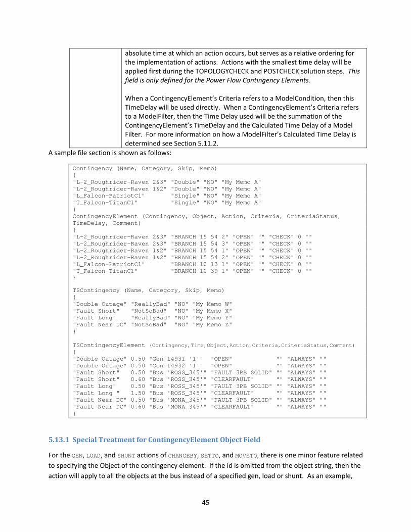
45
absolute time at which an action occurs, but serves as a relative ordering for the implementation of actions. Actions with the smallest time delay will be applied first during the TOPOLOGYCHECK and POSTCHECK solution steps. This field is only defined for the Power Flow Contingency Elements. When a ContingencyElement’s Criteria refers to a ModelCondition, then this TimeDelay will be used directly. When a ContingencyElement’s Criteria refers to a ModelFilter, then the Time Delay used will be the summation of the ContingencyElement’s TimeDelay and the Calculated Time Delay of a Model Filter. For more information on how a ModelFilter’s Calculated Time Delay is determined see Section 5.11.2.
A sample file section is shown as follows:
Contingency (Name, Category, Skip, Memo) { "L-2_Roughrider-Raven 2&3" "Double" "NO" "My Memo A" "L-2_Roughrider-Raven 1&2" "Double" "NO" "My Memo A" "L_Falcon-PatriotC1" "Single" "NO" "My Memo A" "T_Falcon-TitanC1" "Single" "NO" "My Memo A" } ContingencyElement (Contingency, Object, Action, Criteria, CriteriaStatus, TimeDelay, Comment) { "L-2_Roughrider-Raven 2&3" "BRANCH 15 54 2" "OPEN" "" "CHECK" 0 "" "L-2_Roughrider-Raven 2&3" "BRANCH 15 54 3" "OPEN" "" "CHECK" 0 "" "L-2_Roughrider-Raven 1&2" "BRANCH 15 54 1" "OPEN" "" "CHECK" 0 "" "L-2_Roughrider-Raven 1&2" "BRANCH 15 54 2" "OPEN" "" "CHECK" 0 "" "L_Falcon-PatriotC1" "BRANCH 10 13 1" "OPEN" "" "CHECK" 0 "" "T_Falcon-TitanC1" "BRANCH 10 39 1" "OPEN" "" "CHECK" 0 "" }
TSContingency (Name, Category, Skip, Memo) { "Double Outage" "ReallyBad" "NO" "My Memo W" "Fault Short" "NotSoBad" "NO" "My Memo X" "Fault Long" "ReallyBad" "NO" "My Memo Y" "Fault Near DC" "NotSoBad" "NO" "My Memo Z" } TSContingencyElement (Contingency,Time,Object,Action,Criteria,CriteriaStatus,Comment) { "Double Outage" 0.50 "Gen 14931 '1'" "OPEN" "" "ALWAYS" "" "Double Outage" 0.50 "Gen 14932 '1'" "OPEN" "" "ALWAYS" "" "Fault Short" 0.50 "Bus 'ROSS_345'" "FAULT 3PB SOLID" "" "ALWAYS" "" "Fault Short" 0.60 "Bus 'ROSS_345'" "CLEARFAULT" "" "ALWAYS" "" "Fault Long" 0.50 "Bus 'ROSS_345'" "FAULT 3PB SOLID" "" "ALWAYS" "" "Fault Long " 1.50 "Bus 'ROSS_345'" "CLEARFAULT" "" "ALWAYS" "" "Fault Near DC" 0.50 "Bus 'MONA_345'" "FAULT 3PB SOLID" "" "ALWAYS" "" "Fault Near DC" 0.60 "Bus 'MONA_345'" "CLEARFAULT" "" "ALWAYS" "" }
5.13.1 Special Treatment for ContingencyElement Object Field
For the GEN, LOAD, and SHUNT actions of CHANGEBY, SETTO, and MOVETO, there is one minor feature related to specifying the Object of the contingency element. If the id is omitted from the object string, then the action will apply to all the objects at the bus instead of a specified gen, load or shunt. As an example,
46
"GEN 56 '1'" will apply to a specific generator, while "GEN 56" will apply to all generators at the specific bus instead.
When writing out a BRANCH action for OPEN or CLOSE, if the branch is one of the sections of a multi-section line, instead of writing out the FROM and TO Bus identifiers for the specific section in the key field identifiers, write out the FROM and TO bus identifier for the terminal of the multi-section line. When reading in the file, if the specific BRANCH is not found, then the file parser should search for multi-section lines instead.
5.13.2 Criteria Status
Specifies the point during the solution process at which the Criteria (ModelCondition or ModelFilter) is evaluated. For power flow contingency solutions it has the following interpretation
Always : Means to ignore the Criteria and always do the action Never : Means to ignore the Criteria and never do the action Check : Means to evaluate the Criteria in the reference (base) case and implement the
action before a power flow solution is attempted TopologyCheck : The Criteria will be evaluated after Check and Always actions are applied but
BEFORE the power flow solution. The Criteria can evaluate system conditions related to topology changes even before the power flow solution is attempted.
PostCheck : This Criteria will be evaluated AFTER all Check, Always, and TopologyCheck actions have been performed and AFTER the power flow solution is solved

47
For Transient Stability Contingency Elements it has the following interpretation
Always : Means to ignore the Criteria and always do the action Never : Means to ignore the Criteria and never do the action Check : Means to evaluate the Criteria in the initial condition and implement the action
at the specified time during the simulation if the condition is met. This is intended to evaluate a pre-contingency RAS arming condition to determine whether something should be done.
5.13.3 Calculated Time Delay
When a ContingencyElement refers to a ModelFilter, then the Calculated Time Delay used for the Criteria will be a function of both the TimeDelay of the ContingencyElement and any TimeDelays associated with a ModelFilterCondition. The combination of the logic and time delay must be done appropriately so that the evaluation of a ModelFilter will now have both a TRUE/FALSE flag associated with it and a “calculated time delay”. The calculated time delay of a ModelFilter will depend on the whether it is an OR or an AND gate. For an OR gate, the calculated time delay will be equal to the minimum Time Delay associated with any of the ModelFilter’s TRUE inputs. For an AND gate, the calculated time delay will be equal to the maximum Time Delay associated with any of the ModelFilter’s TRUE inputs. (Note: remember that inputs to a ModelFilter can either be TRUE, FALSE or DISABLED).
5.13.4 Contingency Actions
Each object type has a unique set of actions that are available to be applied to the object. The actions available are listed in following tables. We recognize that there may need to be some additions to this list, but this document provides a list of all actions presently available in PowerWorld Simulator. Also remember that the power flow and transient contingencies are separate data structures. The columns in the table are as follows:
1. First column shows the syntax for this action for transient stability contingencies 2. Second column shows the syntax for this action for power flow contingencies 3. Third column describes what the action means. If an action is not presently applicable, then the
first or second column will show “not applicable”.
It should be noted that in many simple cases such as OPEN and CLOSE actions the syntax is the same between the transient stability and power flow contingency elements, but for others they may differ.
Experienced PowerWorld Simulator users may notice that the syntax for the power flow contingencies has been modified and simplified for Simulator Version 18. The old syntax will remain in use and we will maintain forward and backward compatibility. Essentially the new format will form a “secondary key” for the contingency elements. This newer syntax is both simpler for PowerWorld Simulator users and will be easier for other software vendors to parse than our old syntax. The new syntax splits the object and action fields which were previously combined.Many of the actions specify a 'value' string. For power flow contingencies only, this value may be expressed in three ways:
1. A numerical value that will be used directly. The single quotes are not necessary in this case.

48
2. The name of a field of the object (such as described in Section 2.4) in which case that value will be evaluated and used. By appending the word REF at the end of the action string you may also instruct that the field be evaluated in the contingency reference case. Otherwise the value will be evaluated at the moment the action is implemented.
3. The name of a Model Expression. The result of the model expression will then be evaluated and used. By appending the word REF at the end of the action string you may also instruct that the model expression be evaluated in the contingency reference case. Otherwise the value will be evaluated at the moment the action is implemented.
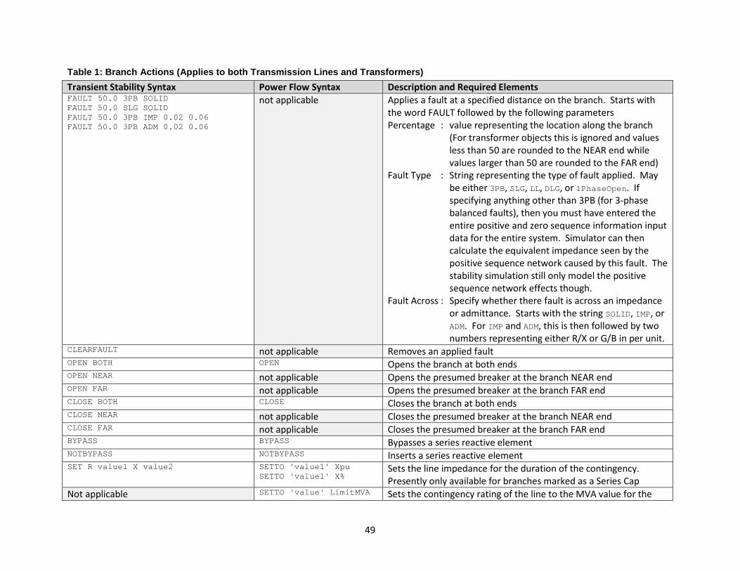
49
Table 1: Branch Actions (Applies to both Transmission Lines and Transformers) Transient Stability Syntax Power Flow Syntax Description and Required Elements FAULT 50.0 3PB SOLID FAULT 50.0 SLG SOLID FAULT 50.0 3PB IMP 0.02 0.06 FAULT 50.0 3PB ADM 0.02 0.06
not applicable Applies a fault at a specified distance on the branch. Starts with the word FAULT followed by the following parameters Percentage : value representing the location along the branch
(For transformer objects this is ignored and values less than 50 are rounded to the NEAR end while values larger than 50 are rounded to the FAR end)
Fault Type : String representing the type of fault applied. May be either 3PB, SLG, LL, DLG, or 1PhaseOpen. If specifying anything other than 3PB (for 3-phase balanced faults), then you must have entered the entire positive and zero sequence information input data for the entire system. Simulator can then calculate the equivalent impedance seen by the positive sequence network caused by this fault. The stability simulation still only model the positive sequence network effects though.
Fault Across : Specify whether there fault is across an impedance or admittance. Starts with the string SOLID, IMP, or ADM. For IMP and ADM, this is then followed by two numbers representing either R/X or G/B in per unit.
CLEARFAULT not applicable Removes an applied fault OPEN BOTH OPEN Opens the branch at both ends OPEN NEAR not applicable Opens the presumed breaker at the branch NEAR end OPEN FAR not applicable Opens the presumed breaker at the branch FAR end CLOSE BOTH CLOSE Closes the branch at both ends CLOSE NEAR not applicable Closes the presumed breaker at the branch NEAR end CLOSE FAR not applicable Closes the presumed breaker at the branch FAR end BYPASS BYPASS Bypasses a series reactive element NOTBYPASS NOTBYPASS Inserts a series reactive element SET R value1 X value2 SETTO 'value1' Xpu
SETTO 'value1' X% Sets the line impedance for the duration of the contingency. Presently only available for branches marked as a Series Cap
Not applicable SETTO 'value' LimitMVA Sets the contingency rating of the line to the MVA value for the
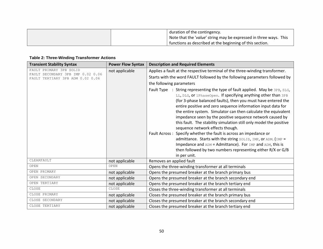
50
duration of the contingency. Note that the 'value' string may be expressed in three ways. This functions as described at the beginning of this section.
Table 2: Three-Winding Transformer Actions Transient Stability Syntax Power Flow Syntax Description and Required Elements FAULT PRIMARY 3PB SOLID FAULT SECONDARY 3PB IMP 0.02 0.06 FAULT TERTIARY 3PB ADM 0.02 0.06
not applicable Applies a fault at the respective terminal of the three-winding transformer. Starts with the word FAULT followed by the following parameters followed by the following parameters Fault Type : String representing the type of fault applied. May be 3PB, SLG,
LL, DLG, or 1PhaseOpen. If specifying anything other than 3PB (for 3-phase balanced faults), then you must have entered the entire positive and zero sequence information input data for the entire system. Simulator can then calculate the equivalent impedance seen by the positive sequence network caused by this fault. The stability simulation still only model the positive sequence network effects though.
Fault Across : Specify whether the fault is across an impedance or admittance. Starts with the string SOLID, IMP, or ADM. (IMP = Impedance and ADM = Admittance). For IMP and ADM, this is then followed by two numbers representing either R/X or G/B in per unit.
CLEARFAULT not applicable Removes an applied fault OPEN OPEN Opens the three-winding transformer at all terminals OPEN PRIMARY not applicable Opens the presumed breaker at the branch primary bus OPEN SECONDARY not applicable Opens the presumed breaker at the branch secondary end OPEN TERTIARY not applicable Opens the presumed breaker at the branch tertiary end CLOSE CLOSE Closes the three-winding transformer at all terminals CLOSE PRIMARY not applicable Closes the presumed breaker at the branch primary bus CLOSE SECONDARY not applicable Closes the presumed breaker at the branch secondary end CLOSE TERTIARY not applicable Closes the presumed breaker at the branch tertiary end
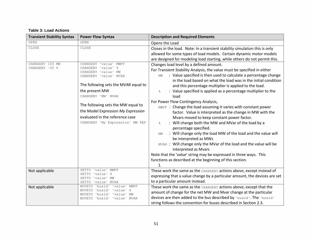
51
Table 3: Load Actions Transient Stability Syntax Power Flow Syntax Description and Required Elements OPEN OPEN Opens the Load CLOSE CLOSE Closes in the load. Note: In a transient stability simulation this is only
allowed for some types of load models. Certain dynamic motor models are designed for modeling load starting, while others do not permit this.
CHANGEBY 100 MW CHANGEBY -30 %
CHANGEBY 'value' MWPF CHANGEBY 'value' % CHANGEBY 'value' MW CHANGEBY 'value' MVAR
The following sets the MVAR equal to the present MW CHANGEBY 'MW' MVAR
The following sets the MW equal to the Model Expression My Expression evaluated in the reference case CHANGEBY 'My Expression' MW REF
Changes load level by a defined amount. For Transient Stability Analysis, the value must be specified in either
MW : Value specified is then used to calculate a percentage change in the load based on what the load was in the initial condition and this percentage multiplier is applied to the load.
% : Value specified is applied as a percentage multiplier to the load
For Power Flow Contingency Analysis, MWPF : Change the load assuming it varies with constant power
factor. Value is interpreted as the change in MW with the Mvars moved to keep constant power factor.
% : Will change both the MW and MVar of the load by a percentage specified.
MW : Will change only the load MW of the load and the value will be interpreted as MWs
MVAR : Will change only the MVar of the load and the value will be interpreted as Mvars
Note that the 'value' string may be expressed in three ways. This functions as described at the beginning of this section.
1. Not applicable SETTO 'value' MWPF
SETTO 'value' % SETTO 'value' MW SETTO 'value' MVAR
These work the same as the CHANGEBY actions above, except instead of expressing that a value change by a particular amount, the devices are set to a particular amount instead.
Not applicable MOVETO 'busid' 'value' MWPF MOVETO 'busid' 'value' % MOVETO 'busid' 'value' MW MOVETO 'busid' 'value' MVAR
These work the same as the CHANGEBY actions above, except that the amount of change for the net MW and Mvar change at the particular devices are then added to the bus described by 'busid'. The 'busid' string follows the convention for buses described in Section 2.3.

52
Table 4: Generator Actions Transient Stability Syntax Power Flow Syntax Description and Required Elements OPEN OPEN Opens the generator CLOSE CLOSE Closes in the generator. Note: In a transient stability
simulation this is only allowed for some types of generator models. Certain dynamic motor models that are modeled as a generator (MOTOR1) are designed for modeling load starting, while others do not permit this.
Not applicable CHANGEBY 'value' % CHANGEBY 'value' MW CHANGEBY 'value' MVAR CHANGEBY 'value' Vpu
The following sets the MVAR equal to the present MW CHANGEBY 'MW' MVAR
The following sets the MW equal to the Model Expression My Expression evaluated in the reference case CHANGEBY 'My Expression' MW REF
Changes generation level by a defined amount. For Transient Stability Analysis, this is not available. For Power Flow Contingency Analysis,
% : Will change the MW only of the generator by a percentage specified.
MW : Will change only the MW of the generator and the value will be interpreted as MWs
MVAR : will change only the MVar of the generator and the value will be interpreted as Mvars
Vpu : will change the generator setpoint voltage and the value will be interpreted as per unit voltage
Note that the 'value' string may be expressed in three ways. This functions the as described at the beginning of this section.
Not applicable SETTO 'value' % SETTO 'value' MW SETTO 'value' MVAR SETTO 'value' Vpu
These work the same as the CHANGEBY actions above, except instead of expressing that a value change by a particular amount, the devices are set to a particular amount instead.
Not applicable MOVETO 'busid' 'value' % MOVETO 'busid' 'value' MW
These work the same as the CHANGEBY actions above, except that they only function on the MW values. The amount of change for the net MW change at the particular devices are then added to the bus described by 'busid'. The 'busid' string follows the convention for buses described in Section 2.3.
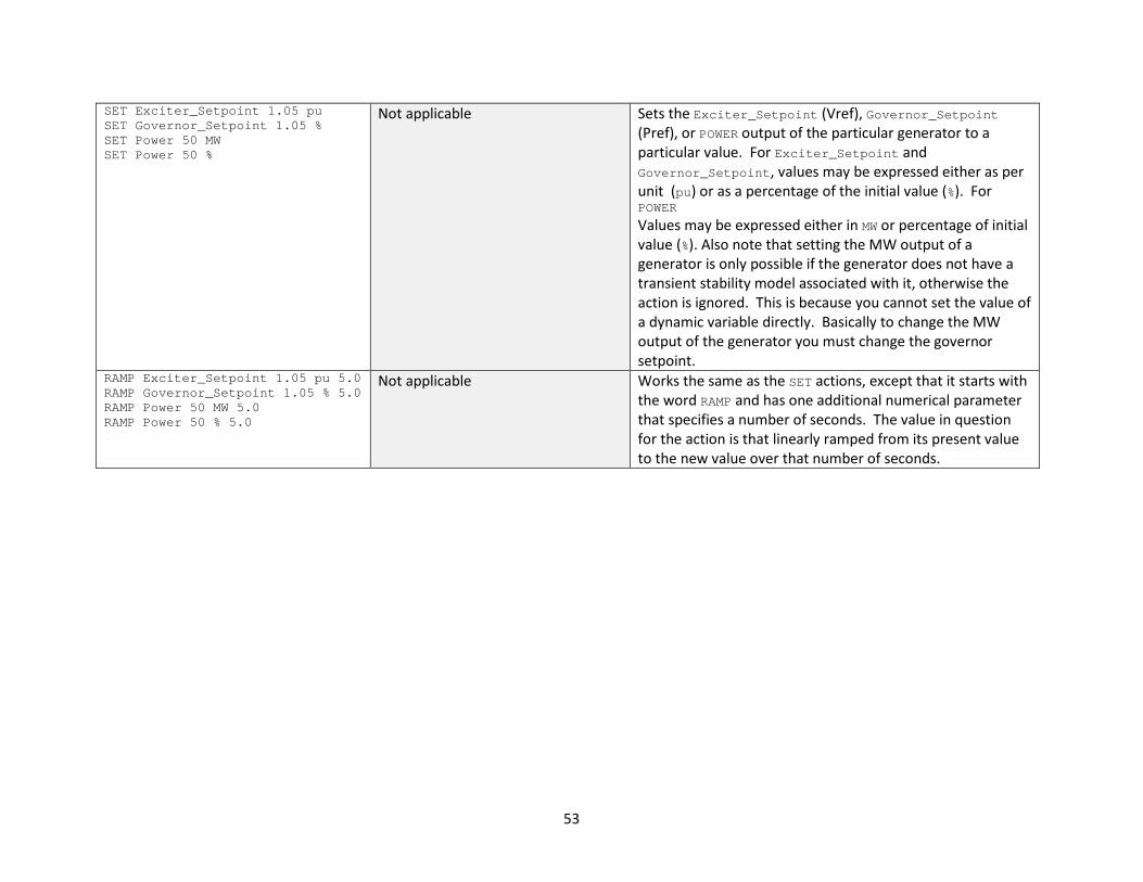
53
SET Exciter_Setpoint 1.05 pu SET Governor_Setpoint 1.05 % SET Power 50 MW SET Power 50 %
Not applicable Sets the Exciter_Setpoint (Vref), Governor_Setpoint (Pref), or POWER output of the particular generator to a particular value. For Exciter_Setpoint and Governor_Setpoint, values may be expressed either as per unit (pu) or as a percentage of the initial value (%). For POWER Values may be expressed either in MW or percentage of initial value (%). Also note that setting the MW output of a generator is only possible if the generator does not have a transient stability model associated with it, otherwise the action is ignored. This is because you cannot set the value of a dynamic variable directly. Basically to change the MW output of the generator you must change the governor setpoint.
RAMP Exciter_Setpoint 1.05 pu 5.0 RAMP Governor_Setpoint 1.05 % 5.0 RAMP Power 50 MW 5.0 RAMP Power 50 % 5.0
Not applicable Works the same as the SET actions, except that it starts with the word RAMP and has one additional numerical parameter that specifies a number of seconds. The value in question for the action is that linearly ramped from its present value to the new value over that number of seconds.
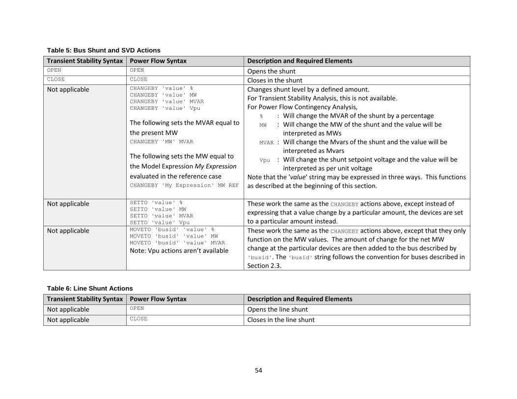
54
Table 5: Bus Shunt and SVD Actions Transient Stability Syntax Power Flow Syntax Description and Required Elements OPEN OPEN Opens the shunt CLOSE CLOSE Closes in the shunt Not applicable CHANGEBY 'value' %
CHANGEBY 'value' MW CHANGEBY 'value' MVAR CHANGEBY 'value' Vpu
The following sets the MVAR equal to the present MW CHANGEBY 'MW' MVAR
The following sets the MW equal to the Model Expression My Expression evaluated in the reference case CHANGEBY 'My Expression' MW REF
Changes shunt level by a defined amount. For Transient Stability Analysis, this is not available. For Power Flow Contingency Analysis,
% : Will change the MVAR of the shunt by a percentage MW : Will change the MW of the shunt and the value will be
interpreted as MWs MVAR : Will change the Mvars of the shunt and the value will be
interpreted as Mvars Vpu : Will change the shunt setpoint voltage and the value will be
interpreted as per unit voltage Note that the 'value' string may be expressed in three ways. This functions as described at the beginning of this section.
Not applicable SETTO 'value' % SETTO 'value' MW SETTO 'value' MVAR SETTO 'value' Vpu
These work the same as the CHANGEBY actions above, except instead of expressing that a value change by a particular amount, the devices are set to a particular amount instead.
Not applicable MOVETO 'busid' 'value' % MOVETO 'busid' 'value' MW MOVETO 'busid' 'value' MVAR
Note: Vpu actions aren’t available
These work the same as the CHANGEBY actions above, except that they only function on the MW values. The amount of change for the net MW change at the particular devices are then added to the bus described by 'busid'. The 'busid' string follows the convention for buses described in Section 2.3.
Table 6: Line Shunt Actions Transient Stability Syntax Power Flow Syntax Description and Required Elements Not applicable OPEN Opens the line shunt Not applicable CLOSE Closes in the line shunt
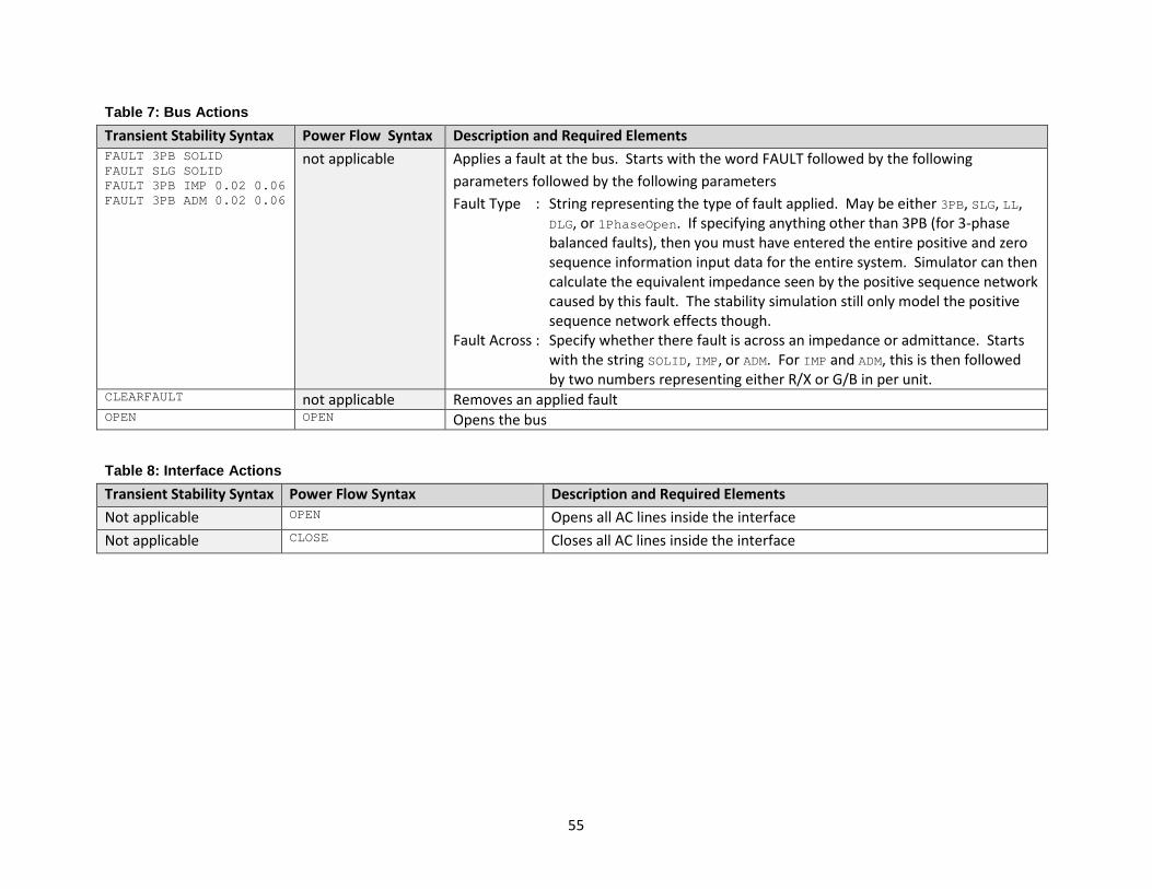
55
Table 7: Bus Actions Transient Stability Syntax Power Flow Syntax Description and Required Elements FAULT 3PB SOLID FAULT SLG SOLID FAULT 3PB IMP 0.02 0.06 FAULT 3PB ADM 0.02 0.06
not applicable Applies a fault at the bus. Starts with the word FAULT followed by the following parameters followed by the following parameters Fault Type : String representing the type of fault applied. May be either 3PB, SLG, LL,
DLG, or 1PhaseOpen. If specifying anything other than 3PB (for 3-phase balanced faults), then you must have entered the entire positive and zero sequence information input data for the entire system. Simulator can then calculate the equivalent impedance seen by the positive sequence network caused by this fault. The stability simulation still only model the positive sequence network effects though.
Fault Across : Specify whether there fault is across an impedance or admittance. Starts with the string SOLID, IMP, or ADM. For IMP and ADM, this is then followed by two numbers representing either R/X or G/B in per unit.
CLEARFAULT not applicable Removes an applied fault OPEN OPEN Opens the bus
Table 8: Interface Actions Transient Stability Syntax Power Flow Syntax Description and Required Elements Not applicable OPEN Opens all AC lines inside the interface Not applicable CLOSE Closes all AC lines inside the interface

56
Table 9: Injection Group Actions Transient Stability Syntax
Power Flow Syntax Description and Required Elements
OPEN 200 MW GEN OPEN 500 MW LOAD OPEN 100 MVAR LOAD OPEN 400 MVAR SHUNT
Not Applicable Opens generators, loads or shunts up until the total MW or Mvar removed would exceeds the value specified. The MW or Mvar values are based on the initial conditions. The order precedence of which devices are opened is determined by the participation factor of the participation point. Higher participation factors are processed first.
Not applicable OPEN OPEN 'value'
The following will evaluate the participation factors in the reference case: OPEN 'value' PPREF
The following will evaluate the participation factors in the reference case and the 'value' in the reference case: OPEN 'value' REF PPREF
Opens all devices in the injection group if no value is specified. If a value is specified, only that number of devices is opened in the injection group in the order of highest to lowest participation factor. Note that the 'value' string may be expressed in three ways. This functions as described at the beginning of this section. See comment below about evaluating participation factors in the reference case.
Not applicable CLOSE Closes all devices in the injection group Not applicable CHANGEBY 'value' %
CHANGEBY 'value' MW CHANGEBY 'value' MWMERITORDER CHANGEBY 'value' MWMERITORDEROPEN
The following sets the MW equal to the present MVAR: CHANGEBY 'MVAR' MW
The following sets the MW equal to the Model Expression My Expression evaluated in the reference case: CHANGEBY 'My Expression' MW REF
The following sets the MW equal to the
Changes MW injection by a defined amount. For Transient Stability Analysis, this is not available. For Power Flow Contingency Analysis the following options are available: For the following two options, the change in the injections will be done proportional to the participation factors of the participation points.
% : Will change the MW injection of the group by a percentage of the existing injection.
MW : Will change the MW injection of the group and the value will be interpreted as MWs
See comments in Section 5.13.5 for the following choices. %MERITORDER : Will change the MW injection of the group by
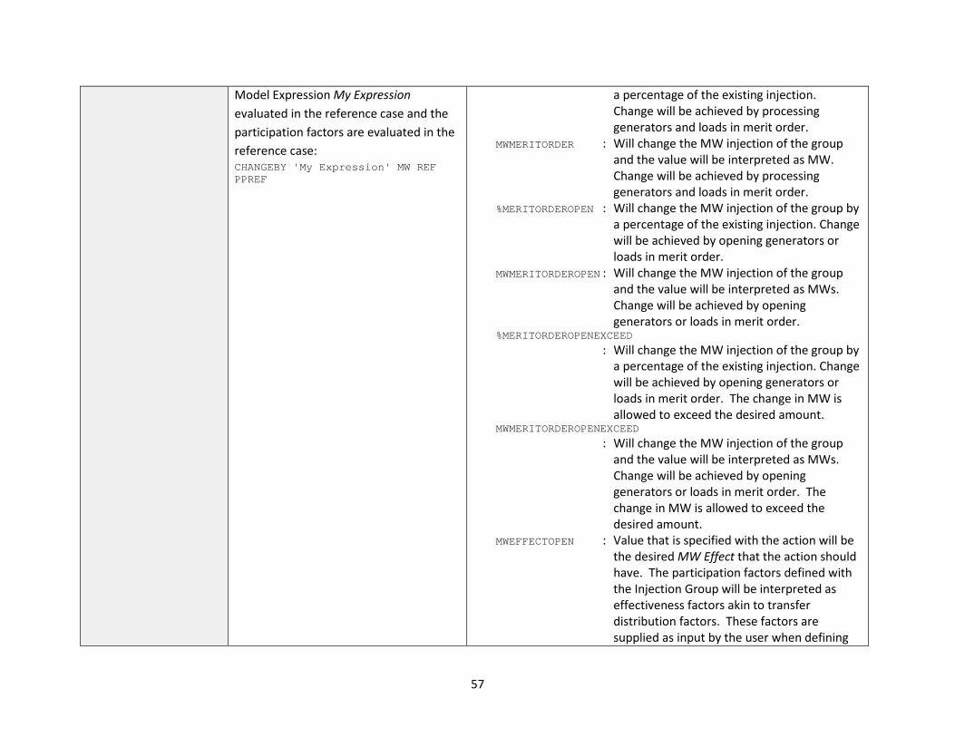
57
Model Expression My Expression evaluated in the reference case and the participation factors are evaluated in the reference case: CHANGEBY 'My Expression' MW REF PPREF
a percentage of the existing injection. Change will be achieved by processing generators and loads in merit order.
MWMERITORDER : Will change the MW injection of the group and the value will be interpreted as MW. Change will be achieved by processing generators and loads in merit order.
%MERITORDEROPEN : Will change the MW injection of the group by a percentage of the existing injection. Change will be achieved by opening generators or loads in merit order.
MWMERITORDEROPEN : Will change the MW injection of the group and the value will be interpreted as MWs. Change will be achieved by opening generators or loads in merit order.
%MERITORDEROPENEXCEED
: Will change the MW injection of the group by a percentage of the existing injection. Change will be achieved by opening generators or loads in merit order. The change in MW is allowed to exceed the desired amount.
MWMERITORDEROPENEXCEED
: Will change the MW injection of the group and the value will be interpreted as MWs. Change will be achieved by opening generators or loads in merit order. The change in MW is allowed to exceed the desired amount.
MWEFFECTOPEN : Value that is specified with the action will be the desired MW Effect that the action should have. The participation factors defined with the Injection Group will be interpreted as effectiveness factors akin to transfer distribution factors. These factors are supplied as input by the user when defining

58
the injection group. The effectiveness factors are multiplied by the present output of generators (or loads) in the injection group to determine how much effect they will have if dropped. The action will find the smallest number of generator (or loads) to drop which results in a total MW Effect that is within 5% of the desired MW Effect, but does not exceed the desired MW Effect.
MWEFFECTOPENEXCEED : Same as MWEFFECTOPEN, but it will ensure that the total MW Effect is within 5% of the desired MW Effect and also meets or exceeds the desired MW Effect.
Note that the 'value' string may be expressed in three ways. This functions as described at the beginning of this section. See comment below about evaluating participation factors in the reference case. Also see comment regarding PARTPOINT objects which refer to another injection group.
SETTO 'value' % SETTO 'value' MW SETTO 'value' MWMERITORDER SETTO 'value' %MWMERITORDEROPEN
These work the same as the CHANGEBY actions above, except instead of expressing that a value change by a particular amount, the devices are set to a particular amount instead. Note: MWEFFECT is not valid for the SETTO actions.
When an action uses participation factors to determine a change, the AutoCalcMethod for the participation factor may allow the value of the participation factor to be dynamically determined. If using an appropriate AutoCalcMethod and AutoCalc is set to YES, an additional option is available to allow participation factors to be evaluated in the reference case. This is indicated by appending PPREF after the value. See Section 5.8 for more information on the AutoCalcMethod. Injection Group can contain PartPoints which reference another Injection Group. The treatment of Injection Groups defined within Injection Groups will be interpreted to drop the entire contained Injection Group when using the MWMERITORDEROPEN type actions.

59
Table 10: DC Converter Actions Transient Stability Syntax Power Flow Syntax Description and Required Elements Not Applicable OPEN Opens the multi-terminal DC Converter Not Applicable CLOSE 'value' MW
CLOSE 'value' Amps
Closes in the multi-terminal DC Converter. Must also specify the MW or Amps setting of the converter as well. Note that the 'value' string may be expressed in three ways. This functions as described at the beginning of this section.
Not Applicable CHANGEBY 'value' % CHANGEBY 'value' MW CHANGEBY 'value' Amps
Changes the multi-terminal DC Converter set-point by an incremental amount of MW or Amp. May also specify the change as a percentage of the present set-point. Note that the 'value' string may be expressed in three ways. This functions as described at the beginning of this section.
Not Applicable SETTO 'value' % SETTO 'value' MW SETTO 'value' Amps
These work the same as the CHANGEBY actions above, except instead of expressing that a value change by a particular amount, the setpoint is set to a particular amount instead.
Not Applicable Not Applicable Ramping values not added presently. Table 11: DC Line Actions Transient Stability Syntax Power Flow Syntax Description and Required Elements OPEN OPEN Opens the two-terminal DC Line Not Applicable CLOSE 'value' MW
CLOSE 'value' Amps
Closes in the two-terminal DC Line. Must also specify the MW or Amps setting of the converter as well. Note that the 'value' string may be expressed in three ways. This functions as described at the beginning of this section.
Not Applicable CHANGEBY 'value' % CHANGEBY 'value' MW CHANGEBY 'value' Amps
Changes the two-terminal DC Line set-point by an incremental amount of MW or Amp. May also specify the change as a percentage of the present set-point. Note that the 'value' string may be expressed in three ways. This functions as described at the beginning of this section.
Not Applicable SETTO 'value' % SETTO 'value' MW SETTO 'value' Amps SETTO 'value' OHMS
These work the same as the CHANGEBY actions above, except instead of expressing that a value change by a particular amount, the setpoint is set to a particular amount instead. SETTO actions also allow the resistance of the DC Line to be set by using the OHMS setting. There is no CHANGEBY action that will adjust the resistance.
Not Applicable Not Applicable Ramping values not added presently.

60
Table 12: Substation Actions Transient Stability Syntax Power Flow Syntax Description and Required Elements Not Applicable OPEN Opens the substation
61
5.13.5 Special InjectionGroup Contingency Action for Generators by Merit Order
Normally all generators and loads in the injection group are adjusted according to their relative participation factors. All with non-zero participation factors will be adjusted to meet the desired injection. When using the option MWMERITORDER or %MERITORDER, generators and loads will be adjusted in order of highest relative participation factor to lowest with each element in the list being adjusted until it hits either its maximum or minimum MW limit before moving on to the next element. This process continues until the desired injection is met. Generator status will not be changed in the process, which means all online generators will continue to provide Mvar support. Loads that have both their minimum and maximum MW limits set to zero will not be allowed to increase. They can only decrease to 0 MW.
There are also options MWMERITORDEROPEN and %MERITORDEROPEN. When using these, if the MW output requested is lower than the existing MW injection of the injection group, then the merit order dispatch will be modified by only opening generators. (Note: the expectation is that the ChangeBy option would most frequently be used with this option with a negative value.) If requested injection is lower, the generator in the injection group with the highest participation factor will have its status changed to Open, followed by the second generator and so on. This will continue until the amount of MW opened is as close to the desired amount as possible but has not exceeded the desired amount of change. If opening a generator will cause the amount of MW opened to exceed the desired amount, that generator will be skipped and the next one in merit order will be examined. If the MW injection requested is higher than the present MW injection, loads will be opened in the same manner. If the MW injection requested is higher than the present MW injection and there are no loads in the injection group, generators will be increased toward their maximum MW output in the same manner as done for MWMERITORDER or %MERITORDER. If the MW injection requested is lower than the present MW injection and there are no generators in the injection group, loads will be increased toward their maximum MW output in the same manner as done for MWMERITORDER or %MERITORDER.
The options MWMERITORDEROPENEXCEED and %MERITORDEROPENEXCEED are very similar to the MWMERITORDEROPEN and %MERITORDEROPEN options except that the amount of MW opened is allowed to exceed the desired amount of change. Generators or loads will be opened in merit order until the desired amount is met or exceeded.
5.14 RemedialAction and RemedialActionElement
RemedialActions are intended to be named containers of actions representing RAS. The elements of each remedial action are inherently applied to every contingency. The fields recognized by the RemedialAction object type are the same as for the Contingency object type. The exception is that no Category is assigned to the RemedialActionScheme.
The fields recognized by the RemedialActionElement object type are the same as for the ContingencyElement object type except for one additional field called InclusionFilter which is described as follows.
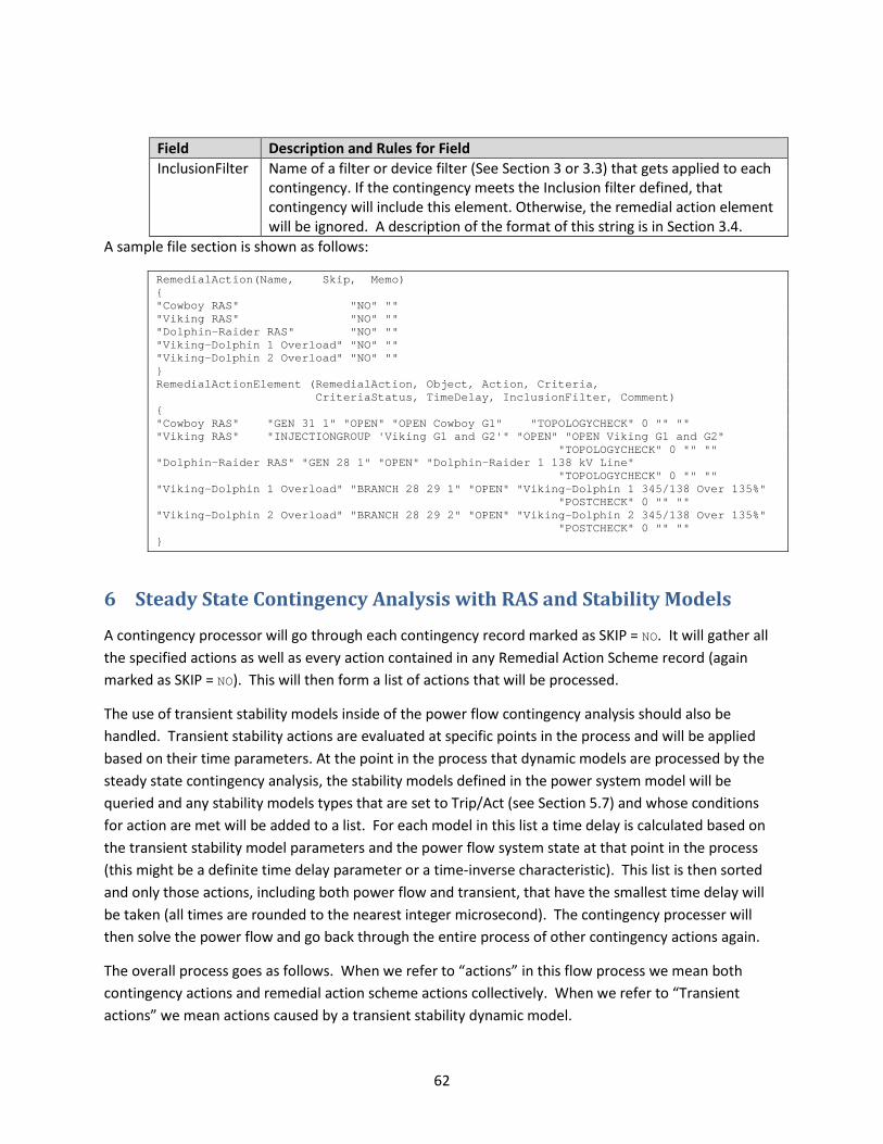
62
Field Description and Rules for Field InclusionFilter Name of a filter or device filter (See Section 3 or 3.3) that gets applied to each
contingency. If the contingency meets the Inclusion filter defined, that contingency will include this element. Otherwise, the remedial action element will be ignored. A description of the format of this string is in Section 3.4.
A sample file section is shown as follows:
RemedialAction(Name, Skip, Memo) { "Cowboy RAS" "NO" "" "Viking RAS" "NO" "" "Dolphin-Raider RAS" "NO" "" "Viking-Dolphin 1 Overload" "NO" "" "Viking-Dolphin 2 Overload" "NO" "" } RemedialActionElement (RemedialAction, Object, Action, Criteria, CriteriaStatus, TimeDelay, InclusionFilter, Comment) { "Cowboy RAS" "GEN 31 1" "OPEN" "OPEN Cowboy G1" "TOPOLOGYCHECK" 0 "" "" "Viking RAS" "INJECTIONGROUP 'Viking G1 and G2'" "OPEN" "OPEN Viking G1 and G2" "TOPOLOGYCHECK" 0 "" "" "Dolphin-Raider RAS" "GEN 28 1" "OPEN" "Dolphin-Raider 1 138 kV Line" "TOPOLOGYCHECK" 0 "" "" "Viking-Dolphin 1 Overload" "BRANCH 28 29 1" "OPEN" "Viking-Dolphin 1 345/138 Over 135%" "POSTCHECK" 0 "" "" "Viking-Dolphin 2 Overload" "BRANCH 28 29 2" "OPEN" "Viking-Dolphin 2 345/138 Over 135%" "POSTCHECK" 0 "" "" }
6 Steady State Contingency Analysis with RAS and Stability Models
A contingency processor will go through each contingency record marked as SKIP = NO. It will gather all the specified actions as well as every action contained in any Remedial Action Scheme record (again marked as SKIP = NO). This will then form a list of actions that will be processed.
The use of transient stability models inside of the power flow contingency analysis should also be handled. Transient stability actions are evaluated at specific points in the process and will be applied based on their time parameters. At the point in the process that dynamic models are processed by the steady state contingency analysis, the stability models defined in the power system model will be queried and any stability models types that are set to Trip/Act (see Section 5.7) and whose conditions for action are met will be added to a list. For each model in this list a time delay is calculated based on the transient stability model parameters and the power flow system state at that point in the process (this might be a definite time delay parameter or a time-inverse characteristic). This list is then sorted and only those actions, including both power flow and transient, that have the smallest time delay will be taken (all times are rounded to the nearest integer microsecond). The contingency processer will then solve the power flow and go back through the entire process of other contingency actions again.
The overall process goes as follows. When we refer to “actions” in this flow process we mean both contingency actions and remedial action scheme actions collectively. When we refer to “Transient actions” we mean actions caused by a transient stability dynamic model.
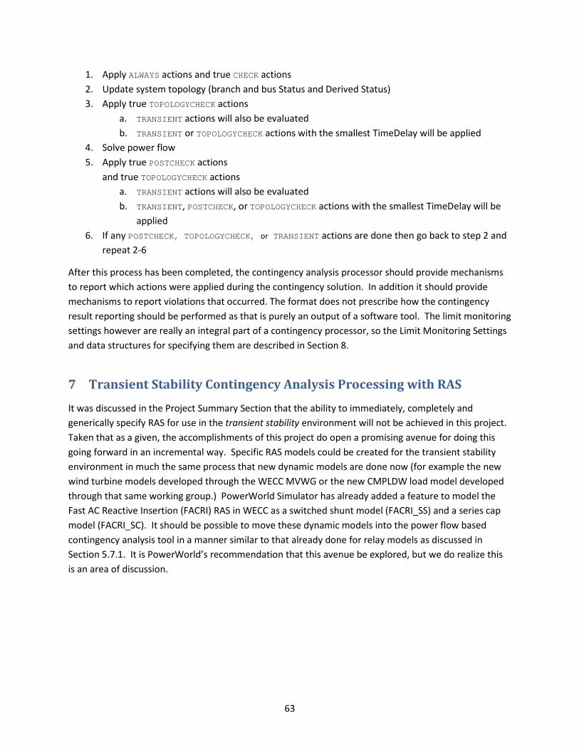
63
1. Apply ALWAYS actions and true CHECK actions 2. Update system topology (branch and bus Status and Derived Status) 3. Apply true TOPOLOGYCHECK actions
a. TRANSIENT actions will also be evaluated b. TRANSIENT or TOPOLOGYCHECK actions with the smallest TimeDelay will be applied
4. Solve power flow 5. Apply true POSTCHECK actions
and true TOPOLOGYCHECK actions a. TRANSIENT actions will also be evaluated b. TRANSIENT, POSTCHECK, or TOPOLOGYCHECK actions with the smallest TimeDelay will be
applied 6. If any POSTCHECK, TOPOLOGYCHECK, or TRANSIENT actions are done then go back to step 2 and
repeat 2-6
After this process has been completed, the contingency analysis processor should provide mechanisms to report which actions were applied during the contingency solution. In addition it should provide mechanisms to report violations that occurred. The format does not prescribe how the contingency result reporting should be performed as that is purely an output of a software tool. The limit monitoring settings however are really an integral part of a contingency processor, so the Limit Monitoring Settings and data structures for specifying them are described in Section 8.
7 Transient Stability Contingency Analysis Processing with RAS
It was discussed in the Project Summary Section that the ability to immediately, completely and generically specify RAS for use in the transient stability environment will not be achieved in this project. Taken that as a given, the accomplishments of this project do open a promising avenue for doing this going forward in an incremental way. Specific RAS models could be created for the transient stability environment in much the same process that new dynamic models are done now (for example the new wind turbine models developed through the WECC MVWG or the new CMPLDW load model developed through that same working group.) PowerWorld Simulator has already added a feature to model the Fast AC Reactive Insertion (FACRI) RAS in WECC as a switched shunt model (FACRI_SS) and a series cap model (FACRI_SC). It should be possible to move these dynamic models into the power flow based contingency analysis tool in a manner similar to that already done for relay models as discussed in Section 5.7.1. It is PowerWorld’s recommendation that this avenue be explored, but we do realize this is an area of discussion.
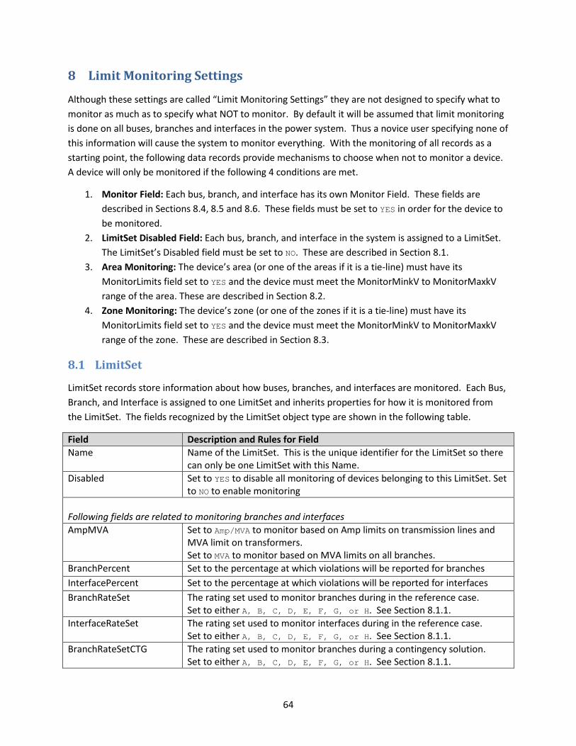
64
8 Limit Monitoring Settings
Although these settings are called “Limit Monitoring Settings” they are not designed to specify what to monitor as much as to specify what NOT to monitor. By default it will be assumed that limit monitoring is done on all buses, branches and interfaces in the power system. Thus a novice user specifying none of this information will cause the system to monitor everything. With the monitoring of all records as a starting point, the following data records provide mechanisms to choose when not to monitor a device. A device will only be monitored if the following 4 conditions are met.
1. Monitor Field: Each bus, branch, and interface has its own Monitor Field. These fields are described in Sections 8.4, 8.5 and 8.6. These fields must be set to YES in order for the device to be monitored.
2. LimitSet Disabled Field: Each bus, branch, and interface in the system is assigned to a LimitSet. The LimitSet’s Disabled field must be set to NO. These are described in Section 8.1.
3. Area Monitoring: The device’s area (or one of the areas if it is a tie-line) must have its MonitorLimits field set to YES and the device must meet the MonitorMinkV to MonitorMaxkV range of the area. These are described in Section 8.2.
4. Zone Monitoring: The device’s zone (or one of the zones if it is a tie-line) must have its MonitorLimits field set to YES and the device must meet the MonitorMinkV to MonitorMaxkV range of the zone. These are described in Section 8.3.
8.1 LimitSet
LimitSet records store information about how buses, branches, and interfaces are monitored. Each Bus, Branch, and Interface is assigned to one LimitSet and inherits properties for how it is monitored from the LimitSet. The fields recognized by the LimitSet object type are shown in the following table.
Field Description and Rules for Field Name Name of the LimitSet. This is the unique identifier for the LimitSet so there
can only be one LimitSet with this Name. Disabled Set to YES to disable all monitoring of devices belonging to this LimitSet. Set
to NO to enable monitoring Following fields are related to monitoring branches and interfaces AmpMVA Set to Amp/MVA to monitor based on Amp limits on transmission lines and
MVA limit on transformers. Set to MVA to monitor based on MVA limits on all branches.
BranchPercent Set to the percentage at which violations will be reported for branches InterfacePercent Set to the percentage at which violations will be reported for interfaces BranchRateSet The rating set used to monitor branches during in the reference case.
Set to either A, B, C, D, E, F, G, or H. See Section 8.1.1. InterfaceRateSet The rating set used to monitor interfaces during in the reference case.
Set to either A, B, C, D, E, F, G, or H. See Section 8.1.1. BranchRateSetCTG The rating set used to monitor branches during a contingency solution.
Set to either A, B, C, D, E, F, G, or H. See Section 8.1.1.
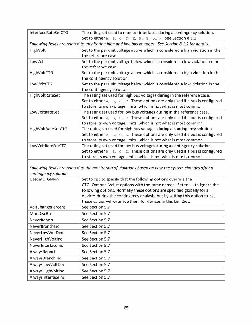
65
InterfaceRateSetCTG The rating set used to monitor interfaces during a contingency solution. Set to either A, B, C, D, E, F, G, or H. See Section 8.1.1.
Following fields are related to monitoring high and low bus voltages. See Section 8.1.2 for details. HighVolt Set to the per unit voltage above which is considered a high violation in the
the reference case. LowVolt Set to the per unit voltage below which is considered a low violation in the
the reference case. HighVoltCTG Set to the per unit voltage above which is considered a high violation in the
the contingency solution. LowVoltCTG Set to the per unit voltage below which is considered a low violation in the
the contingency solution. HighVoltRateSet The rating set used for high bus voltages during in the reference case.
Set to either A, B, C, D. These options are only used if a bus is configured to store its own voltage limits, which is not what is most common.
LowVoltRateSet The rating set used for low bus voltages during in the reference case. Set to either A, B, C, D. These options are only used if a bus is configured to store its own voltage limits, which is not what is most common.
HighVoltRateSetCTG The rating set used for high bus voltages during a contingency solution. Set to either A, B, C, D. These options are only used if a bus is configured to store its own voltage limits, which is not what is most common.
LowVoltRateSetCTG The rating set used for low bus voltages during a contingency solution. Set to either A, B, C, D. These options are only used if a bus is configured to store its own voltage limits, which is not what is most common.
Following fields are related to the monitoring of violations based on how the system changes after a contingency solution. UseSetCTGMon Set to YES to specify that the following options override the
CTG_Options_Value options with the same names. Set to NO to ignore the following options. Normally these options are specified globally for all devices during the contingency analysis, but by setting this option to YES these values will override them for devices in this LimitSet.
VoltChangePercent See Section 5.7 MonDiscBus See Section 5.7 NeverReport See Section 5.7 NeverBranchInc See Section 5.7 NeverLowVoltDec See Section 5.7 NeverHighVoltInc See Section 5.7 NeverInterfaceInc See Section 5.7 AlwaysReport See Section 5.7 AlwaysBranchInc See Section 5.7 AlwaysLowVoltDec See Section 5.7 AlwaysHighVoltInc See Section 5.7 AlwaysInterfaceInc See Section 5.7

66
A sample file section is shown as follows:
LimitSet (Name,LowVolt,HighVolt,BranchPercent,InterfacePercent,NomogramPercent, BranchRateSet,BranchRateSetCTG,InterfaceRateSet,InterfaceRateSetCTG,Disabled, AmpMVA,NeverReport,AlwaysReport,VoltChangePercent,NeverBranchInc, AlwaysBranchInc,NeverLowVoltDec,AlwaysLowVoltDec,NeverHighVoltInc, AlwaysHighVoltInc,NeverInterfaceInc,AlwaysInterfaceInc,MonitorEnd, LowVoltRateSet,HighVoltRateSet,LowVoltRateSetCTG, HighVoltRateSetCTG,LowVoltCTG,HighVoltCTG,MonDiscBus,UseSetCTGMon) { "Default" 0.95 1.05 100.0 100.0 100.0 "A" "B" "A" "B" "NO" "Amp/MVA" "NO" "NO" "NO" 0.0 999.0 0.0 2.0 0.0 2.0 0.0 999.0 "Higher" "A" "A" "B" "B" 0.900 1.100 "NO" "NO" "Limit Set 1" 0.96 1.04 110.0 100.0 100.0 "C" "D" "C" "D" "NO" "Amp/MVA" "NO" "NO" "NO" 0.0 999.0 0.0 2.0 0.0 2.0 0.0 999.0 "Higher" "C" "C" "D" "D" 0.910 1.110 "NO" "NO" "Limit Set 2" 1.00 1.10 120.0 100.0 100.0 "E" "F" "A" "B" "NO" "Amp/MVA" "NO" "NO" "NO" 0.0 999.0 0.0 2.0 0.0 2.0 0.0 999.0 "Higher" "A" "A" "B" "B" 0.950 1.150 "NO" "NO" }
8.1.1 Branch and Interface relationship to LimitSet
Each branch in the underlying power system data records has 8 limits assigned to it. These are referred to as Limit A, B, C, D, E, F, G, and H. The fields associated with the limits are LimitMVAA, LimitMVAB, LimitMVAC, LimitMVAD, LimitMVAE, LimitMVAF, LimitMVAG, and LimitMVAH.
Similarly, each interface has 8 limits (A-H) assigned to it. The fields associated with the limits are LimitMWA, LimitMWB, LimitMWC, LimitMWD, LimitMWE, LimitMWF, LimitMWG, and LimitMWH.
The LimitSet has various fields that specify which rating set to use when monitoring in the contingency reference case or during the post-contingency monitoring. These refer to these A – H limits.
8.1.2 Bus relationship to LimitSet
Traditionally, power flow data records have not stored voltage ratings with each individual bus record. As a result, the typical way that high and low bus limits are assigned to a bus is by assigning the bus to a LimitSet and then configuring the LimitSet fields HighVolt/LowVolt and HighVoltCTG/LowVoltCTG appropriately to assign the High/Low voltage limits during the reference case and post-contingency monitoring respectively.
It is also possible to assign 4 sets of high and low per unit voltage limits for each bus (call them High A, B, C, and D and Low A, B, C, and D). With each bus record, there is then a flag called “Use bus-specific limits”. If this flag is set to YES, the bus limits will be determined by using the LimitSet fields that refer to a “RateSet” in much the same way as is done for Branch and Interface limits as described in Section 8.1.1. The fields associated with these bus-specific limits are as follows: UseSpecificLimits, LimitHighA, LimitHighB, LimitHighC, LimitHighD, LimitLowA, LimitLowB, LimitLowC, and LimitLowD.
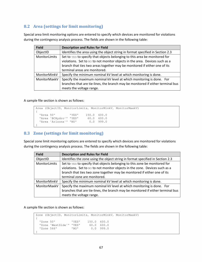
67
8.2 Area (settings for limit monitoring)
Special area limit monitoring options are entered to specify which devices are monitored for violations during the contingency analysis process. The fields are shown in the following table:
Field Description and Rules for Field ObjectID Identifies the area using the object string in format specified in Section 2.3 MonitorLimits Set to YES to specify that objects belonging to this area be monitored for
violations. Set to NO to not monitor objects in the area. Devices such as a branch that ties two areas together may be monitored if either one of its terminal areas are monitored.
MonitorMinkV Specify the minimum nominal kV level at which monitoring is done. MonitorMaxkV Specify the maximum nominal kV level at which monitoring is done. For
branches that are tie-lines, the branch may be monitored if either terminal bus meets the voltage range.
A sample file section is shown as follows:
Area (ObjectID, MonitorLimits, MonitorMinkV, MonitorMaxkV) { "Area 50" "YES" 150.0 600.0 "Area 'BCHydro'" "YES" 60.0 600.0 "Area 'Arizona'" "NO" 0.0 999.0 }
8.3 Zone (settings for limit monitoring)
Special zone limit monitoring options are entered to specify which devices are monitored for violations during the contingency analysis process. The fields are shown in the following table:
Field Description and Rules for Field ObjectID Identifies the zone using the object string in format specified in Section 2.3 MonitorLimits Set to YES to specify that objects belonging to this zone be monitored for
violations. Set to NO to not monitor objects in the zone. Devices such as a branch that ties two zone together may be monitored if either one of its terminal zone are monitored.
MonitorMinkV Specify the minimum nominal kV level at which monitoring is done. MonitorMaxkV Specify the maximum nominal kV level at which monitoring is done. For
branches that are tie-lines, the branch may be monitored if either terminal bus meets the voltage range.
A sample file section is shown as follows:
Zone (ObjectID, MonitorLimits, MonitorMinkV, MonitorMaxkV) { "Zone 50" "YES" 150.0 600.0 "Zone 'WestSide'" "YES" 60.0 600.0 "Zone 566" "NO" 0.0 999.0 }

68
8.4 Bus (settings for limit monitoring)
Special bus limit monitoring options are entered to specify whether to monitor this bus and which LimitSet it belong to. The fields are shown in the following table:
Field Description and Rules for Field ObjectID Identifies the bus using the object string in format specified in Section 2.3 Monitor Set to YES to specify that this bus should be monitored. Set to NO to not
monitor this bus. LimitSet Name of the Limit Set to which the bus belongs
A sample file section is shown as follows:
Bus (ObjectID, Monitor, LimitSet) { "Bus 10" "YES" "Limit Set 1" "Bus 'MyLabel'" "YES" "Limit Set 2" "Bus 'Springfield_345.0'" "YES" "Limit Group 2" }
8.5 Branch (settings for limit monitoring)
Special branch limit monitoring options are entered to specify whether to monitor this branch and which LimitSet it belong to. The fields are shown in the following table:
Field Description and Rules for Field ObjectID Identifies the branch using the object string in format specified in Section 2.3 Monitor Set to YES to specify that this branch should be monitored. Set to NO to not
monitor this branch. LimitSet Name of the Limit Set to which the branch belongs
A sample file section is shown as follows:
Branch (ObjectID, Monitor, LimitSet) { "Branch 10 55 '1'" "YES" "Limit Set 1" "Branch 'MyLabel'" "YES" "Limit Set 2" "Branch 'MyName_345.0' ' MyName _138.0' '2'" "YES" "Limit Group 2" }

69
8.6 Interface (settings for limit monitoring)
Special interface limit monitoring options are entered to specify whether to monitor this interface and which LimitSet it belong to. The fields are shown in the following table:
Field Description and Rules for Field ObjectID Identifies the interface using the object string in format specified in Section 2.3 Monitor Set to YES to specify that this interface s should be monitored. Set to NO to
monitor this interface. LimitSet Name of the Limit Set to which the interface belongs
A sample file section is shown as follows:
Interface (ObjectID, Monitor, LimitSet) { "Interface 'PDCI'" "YES" "Limit Set 1" "Interface 'COI'" "YES" "Limit Set 2" "Interface 'West of Springfield'" "YES" "Limit Group 2" }
8.7 CustomMonitor
Standard limit monitoring in power flow based contingency analysis looks only at branch MVA limits, bus voltage limits, and interface MW limits. These limits are specified in the standard power flow case input data formats already. There may be a need for more specific types of monitoring, which can be achieved by defining a CustomMonitor data record. Examples of such needs are as follows:
1. The monitoring of other fields (say generator MW outputs) 2. Ability to enable or disable monitoring based on the Category of the contingency 3. Ability to use modified monitoring based on a change from the reference case based on
Category of the contingency
The CustomMonitor object has the following fields:
Field Description and Rules for Field Name Unique Name for the custom monitor object Enabled Set to YES to enable this custom monitor.
Set to NO to turn off the use of this monitor. Category A comma delimited list of strings representing the contingency categories
assigned to this custom monitor. A custom monitor will only be used to look for violations during a contingency if at least one category is in common between the Contingency and the CustomMonitor object.
ObjectType Object type to be monitored by this custom monitor. See choices for object types in Section 2.2.
Object If this field is left blank then all objects of the type specified by ObjectType will be monitored by this CustomMonitor. Otherwise a specific object may be specified by entering a string using the format described in Section 2.3.

70
ObjectField Field that is monitored for the objects or object describe by the ObjectType or Object of this record. The fields are the strings described in Section 2.4.
FilterPre Name of a filter or device filter (See Section 3 or 3.3). If this is specified, an object must meet this filter in the contingency reference state in order for it to be monitored in the contingency analysis run. A description of the format of this string is found in Section 3.4. Violations will be reported only if both FilterPre and FilterPost are met.
FilterPost Name of a filter or device filter (See Section 3 or 3.3). If this is specified, an object must meet this filter in the post-contingency state in order for it to report a violation in the contingency analysis tool. A description of the format of this string is found in Section 3.4. Violations will be reported only if both FilterPre and FilterPost are met.
UseMinIncrease Set to YES to specify that a violation should be reported if the increase in the value being monitored is greater than the value specified as MinIncrease. Set to NO to disable this feature.
MinIncrease The value that goes with the UseMinIncrease option UseMinDecrease Set to YES to specify that a violation should be reported if the decrease in
the value being monitored is greater than the value specified as MinDecrease. Set to NO to disable this feature.
MinDecrease The value that goes with the UseMinDecrease option ValueMeaning Meaning of the MinDecrease and MinIncrease values.
Percent : means values should be interpreted as a percent change from the initial value
Actual : means values should be interpreted as the actual change in the units of the field being monitored
A sample file section is shown as follows:
Filter (Name,ObjectType,Logic,FilterPre,Enabled) { "Roughride over Max" "Gen" "AND" "NO " "YES" } Condition (ObjectType,Filter,CondNum,ObjectField,ConditionType,Value,OtherValue,Absolute) { "Gen" "Roughrider Max" 1 "MW" ">" "<Field>MWMax" "" "NO " } CustomMonitor (Name,Enabled,Category,ObjectType,Object,ObjectField,FilterPre, FilterPost,UseMinIncrease,MinIncrease,UseMinDecrease,MinDecrease,ValueMeaning) { "Bus Voltage Drops" "YES" "" "Bus" "" "Vpu" "" "" "YES" 5 "NO " 0 "Percent" // following appears across 2 lines of text. "Roughrider high" "YES" "" "Gen" "Gen '54' '1'" "MW" "" "Roughrider Max" "NO " 0 "NO " 0 "Actual" }

71
9 Final Demonstration
9.1 Saving a file in this format
The data format described in this document has been fully integrated in PowerWorld Simulator Version 18 and will serve as a more concise and readable version of PowerWorld’s Auxiliary File Format. This format builds on that technology but has improved it to make it easier for humans to read and presumably simpler for others to parse. In order to save this file from within the PowerWorld Simulator software tool, one need only open the Contingency Analysis dialog and click on the Save button shown in the following figure.

72
In the Save Dialog that then appears, the Save as Type drop-down should be changed to WECC Contingency and RAS file (*.aux) as shown in the following figure.
Finally, after choosing a file to which to save, another dialog will appear prompting you to choose which type of key identifiers to use when saving the file. The choice of key identifiers was described more in Section 2.3. The dialog will look as shown below.
After clicking Choose, this will then save the file to the hard drive.
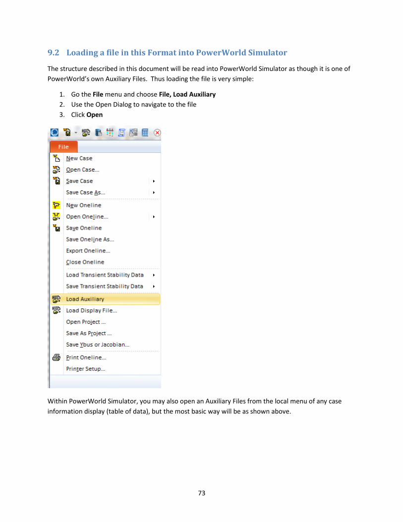
73
9.2 Loading a file in this Format into PowerWorld Simulator
The structure described in this document will be read into PowerWorld Simulator as though it is one of PowerWorld’s own Auxiliary Files. Thus loading the file is very simple:
1. Go the File menu and choose File, Load Auxiliary 2. Use the Open Dialog to navigate to the file 3. Click Open
Within PowerWorld Simulator, you may also open an Auxiliary Files from the local menu of any case information display (table of data), but the most basic way will be as shown above.

74
9.3 Example file in this format
The following represents a sample of all the information described in the previous portions of this document. The file is concise yet contains enough self-documentation that it is human readable.
//-------------------------------------------------------------------- // THE FOLLOWING INJECTION GROUP DEFINITIONS ARE BEING SAVED BY //------------------------------------------------------------------- INJECTIONGROUP (Name) { "Viking G1 and G2" } PARTPOINT (GroupName,Object,AutoCalcMethod,PartFact,AutoCalc) { "Viking G1 and G2" "Gen '28' '1'" "SPECIFIED" 150.00000 "NO " "Viking G1 and G2" "Gen '28' '2'" "SPECIFIED" 150.00000 "NO " } //-------------------------------------------------------------------------------- // THE FOLLOWING LIMIT MONITORING SETTINGS ARE BEING SAVED BY THE CONTINGENCY TOOL. //-------------------------------------------------------------------------------- LIMITSET (Name,LowVolt,HighVolt,BranchPercent,InterfacePercent, BranchRateSet,BranchRateSetCTG,InterfaceRateSet,InterfaceRateSetCTG,Disabled, AmpMVA,NeverReport,AlwaysReport,VoltChangePercent,NeverBranchInc, AlwaysBranchInc,NeverLowVoltDec,AlwaysLowVoltDec,NeverHighVoltInc, AlwaysHighVoltInc,NeverInterfaceInc,AlwaysInterfaceInc, LowVoltRateSet,HighVoltRateSet,LowVoltRateSetCTG, HighVoltRateSetCTG,LowVoltCTG,HighVoltCTG,MonDiscBus,UseSetCTGMon) { "Default" 0.95 1.05 100.0 100.0 "A" "B" "A" "B" "NO" "Amp/MVA" "NO" "NO" "NO" 0.0 999.0 0.0 2.0 0.0 2.0 0.0 999.0 "A" "A" "B" "B" 0.900 1.100 "NO" "NO" "Limit Set 1" 0.96 1.04 110.0 100.0 "C" "D" "C" "D" "NO" "Amp/MVA" "NO" "NO" "NO" 0.0 999.0 0.0 2.0 0.0 2.0 0.0 999.0 "C" "C" "D" "D" 0.910 1.110 "NO" "NO" "Limit Set 2" 1.00 1.10 120.0 100.0 "E" "F" "A" "B" "NO" "Amp/MVA" "NO" "NO" "NO" 0.0 999.0 0.0 2.0 0.0 2.0 0.0 999.0 "A" "A" "B" "B" 0.950 1.150 "NO" "NO" } AREA (ObjectID,MonitorLimits,MonitorMaxkV,MonitorMinkV) { "Area '1'" "YES" 30.0000 345.0000 } ZONE (ObjectID,MonitorLimits,MonitorMaxkV,MonitorMinkV) { "Zone '1'" "YES" 30.0000 345.0000 } SCRIPT { // set all buses to monitored as part of first limit group SetData(Bus, [Monitor,LimitSet], ["YES", "Default"], All); } BUS (ObjectID,Monitor,LimitSet) { "Bus '10'" "YES" "Limit Group 1" "Bus '14'" "YES" "Limit Group 1" "Bus '16'" "YES" "Limit Group 2" "Bus '17'" "YES" "Limit Group 2" } SCRIPT { // set all branches to monitored as part of first limit group SetData(Branch, [Monitor,LimitSet], ["YES", "Default"], All); }

75
BRANCH (ObjectID,Monitor,LimitSet) { "Branch '1' '40' '1'" "YES" "Limit Group 1" "Branch '3' '41' '1'" "YES" "Limit Group 2" "Branch '5' '44' '1'" "YES" "Limit Group 2" "Branch '10' '19' '1'" "YES" "Limit Group 1" "Branch '12' '40' '1'" "YES" "Limit Group 1" } SCRIPT { // set all interfaces to monitored as part of first limit group SetData(Interface, [Monitor,LimitSet], ["YES", "Default"], All); } FILTER (Name,ObjectType,Logic,FilterPre,Enabled) { "Roughride over Max" "Gen" "AND" "NO " "YES" } CONDITION (ObjectType,Filter,CondNum,ObjectField,ConditionType,Value,OtherValue,Absolute) { "Gen" "Roughrider Max" 1 "MW" ">" "<Field>MWMax" "" "NO " } CUSTOMMONITOR (Name,Enabled,Category,ObjectType,Object,ObjectField,FilterPre,FilterPost, UseMinIncrease,MinIncrease,UseMinDecrease,MinDecrease,ValueMeaning) { "Bus Voltage Drops" "YES" "" "Bus" "" "Vpu" "" "" "YES" 5 "NO " 0 "Percent" "Roughrider high" "YES" "" "Gen" "Gen '54' '1'" "MW" "" "Roughrider Max" "NO " 0 "NO " 0 "Actual" } //-------------------------------------------------------------------------------- // THE FOLLOWING SECTION CONTAINS OPTIONS FOR THE CONTINGENCY ANALYSIS. //-------------------------------------------------------------------------------- CTG_OPTIONS_VALUE (VariableName,Value) { "AlwaysReport" "YES" "AlwaysBranchInc" "999" "AlwaysHighVoltInc" "2" "AlwaysInterfaceInc" "999" "AlwaysLowVoltDec" "2" "NeverReport" "YES" "NeverBranchInc" "2" "NeverHighVoltInc" "0" "NeverInterfaceInc" "0" "NeverLowVoltDec" "0" "VoltChangePercent" "NO" "MonDiscBus" "NO" "DisableGenDropOverlap" "NO" "AGCTolerance" "0.05" "MakeUpPower" "Gen Part Factors" "TSModelMaxDelay" "3600" "TSModelsTrip" "" "TSModelsMonitor" "" "DynAssignSlack" "Default" "PUConvergenceTol" "0.001" "DisableOptMult" "Default" "MaxItr" "50" "MinVoltILoad" "Default" "MinVoltSLoad" "Default" "EnforceGenMWLimits" "YES" "LTCTapBalance" "Default" "ChkPhaseShifters" "NO" "ChkSVCs" "NO" "ChkShunts" "NO" "ChkTaps" "NO" "DisableGenMVRCheck" "Default" "ChkVarImmediately" "Default" "MaxItrVoltLoop" "Default" "MinLTCSense" "Default" "ModelPSDiscrete" "Default" "PreventOscillations" "Default" "ShuntInner" "NO" }
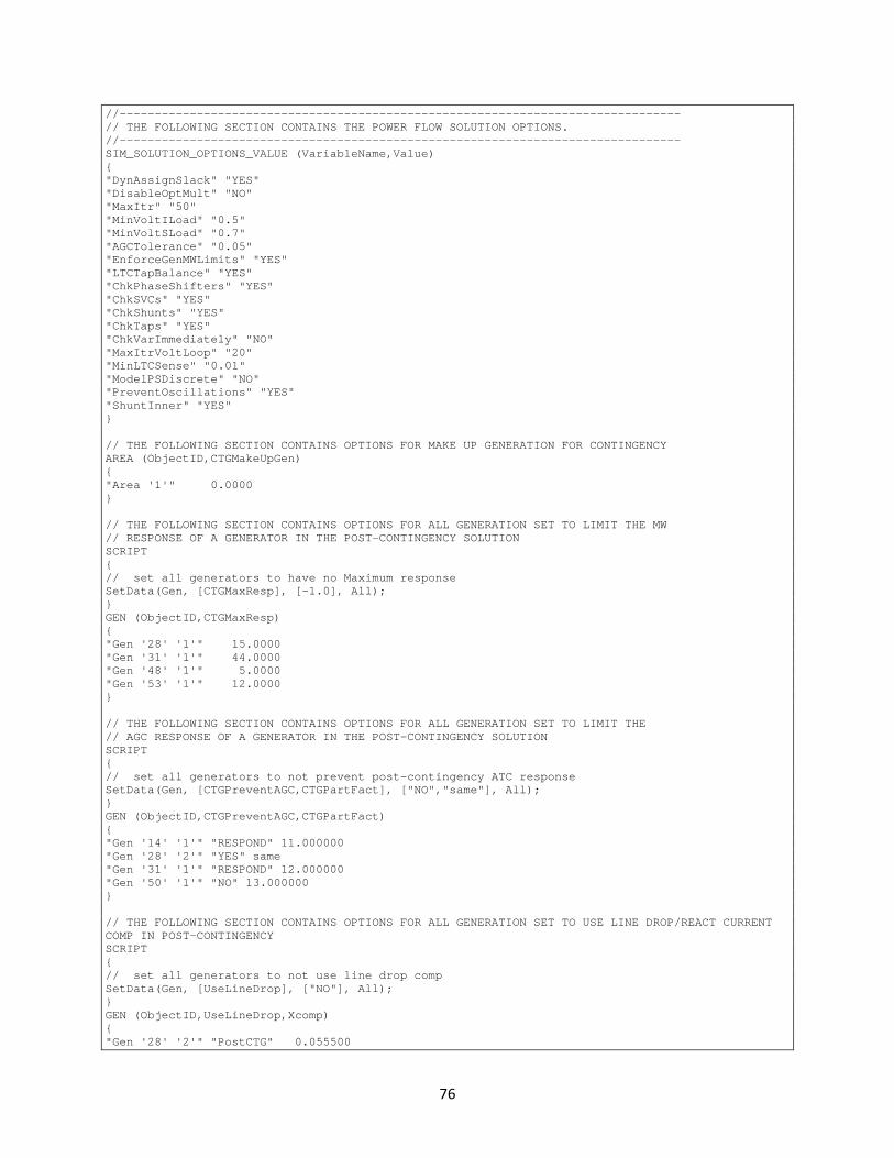
76
//-------------------------------------------------------------------------------- // THE FOLLOWING SECTION CONTAINS THE POWER FLOW SOLUTION OPTIONS. //-------------------------------------------------------------------------------- SIM_SOLUTION_OPTIONS_VALUE (VariableName,Value) { "DynAssignSlack" "YES" "DisableOptMult" "NO" "MaxItr" "50" "MinVoltILoad" "0.5" "MinVoltSLoad" "0.7" "AGCTolerance" "0.05" "EnforceGenMWLimits" "YES" "LTCTapBalance" "YES" "ChkPhaseShifters" "YES" "ChkSVCs" "YES" "ChkShunts" "YES" "ChkTaps" "YES" "ChkVarImmediately" "NO" "MaxItrVoltLoop" "20" "MinLTCSense" "0.01" "ModelPSDiscrete" "NO" "PreventOscillations" "YES" "ShuntInner" "YES" } // THE FOLLOWING SECTION CONTAINS OPTIONS FOR MAKE UP GENERATION FOR CONTINGENCY AREA (ObjectID,CTGMakeUpGen) { "Area '1'" 0.0000 } // THE FOLLOWING SECTION CONTAINS OPTIONS FOR ALL GENERATION SET TO LIMIT THE MW // RESPONSE OF A GENERATOR IN THE POST-CONTINGENCY SOLUTION SCRIPT { // set all generators to have no Maximum response SetData(Gen, [CTGMaxResp], [-1.0], All); } GEN (ObjectID,CTGMaxResp) { "Gen '28' '1'" 15.0000 "Gen '31' '1'" 44.0000 "Gen '48' '1'" 5.0000 "Gen '53' '1'" 12.0000 } // THE FOLLOWING SECTION CONTAINS OPTIONS FOR ALL GENERATION SET TO LIMIT THE // AGC RESPONSE OF A GENERATOR IN THE POST-CONTINGENCY SOLUTION SCRIPT { // set all generators to not prevent post-contingency ATC response SetData(Gen, [CTGPreventAGC,CTGPartFact], ["NO","same"], All); } GEN (ObjectID,CTGPreventAGC,CTGPartFact) { "Gen '14' '1'" "RESPOND" 11.000000 "Gen '28' '2'" "YES" same "Gen '31' '1'" "RESPOND" 12.000000 "Gen '50' '1'" "NO" 13.000000 } // THE FOLLOWING SECTION CONTAINS OPTIONS FOR ALL GENERATION SET TO USE LINE DROP/REACT CURRENT COMP IN POST-CONTINGENCY SCRIPT { // set all generators to not use line drop comp SetData(Gen, [UseLineDrop], ["NO"], All); } GEN (ObjectID,UseLineDrop,Xcomp) { "Gen '28' '2'" "PostCTG" 0.055500
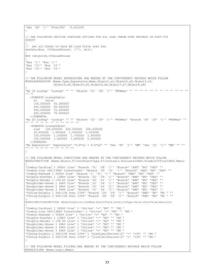
77
"Gen '48' '1'" "PostCTG" -0.051200 } // THE FOLLOWING SECTION CONTAINS OPTIONS FOR ALL LOAD THROW OVER RECORDS IN POST-CTG SCRIPT { // set all buses to have NO load throw over bus SetData(Bus, [CTGLoadThrow], [""], All); } BUS (ObjectID,CTGLoadThrow) { "Bus '3'" "Bus '1'" "Bus '12'" "Bus '10'" "Bus '14'" "Bus '15'" } // THE FOLLOWING MODEL EXPRESSIONS ARE NEEDED BY THE CONTINGENCY RECORDS WHICH FOLLOW MODELEXPRESSION (Name,Type,Expression,Memo,Object1,x1,Object2,x2,Object3,x3, Object4,x4,Object5,x5,Object6,x6,Object7,x7,Object8,x8) { "My 1D Lookup" "Lookup" "" "" "Branch '31' '28' '1'" "MVAMax" "" "" "" "" "" "" "" "" "" "" "" "" "" "" <SUBDATA LookupTable> x1 value 100.000000 50.000000 200.000000 65.000000 300.000000 72.000000 400.000000 75.000000 </SUBDATA> "My 2D Lookup" "Lookup" "" "" "Branch '32' '29' '1'" "MVAMax" "Branch '56' '29' '1'" "MVAMax" "" "" "" "" "" "" "" "" "" "" "" "" <SUBDATA LookupTable> x1x2 100.000000 200.000000 300.000000 50.000000 1.000000 1.450000 1.550000 100.000000 1.500000 1.700000 1.850000 150.000000 1.600000 1.900000 2.000000 </SUBDATA> "My Expression" "Expression" "0.8*x1 + 0.5*x2" "" "Gen '48' '1'" "MW" "Gen '31' '1'" "MW" "" "" "" "" "" "" "" "" "" "" "" "" } // THE FOLLOWING MODEL CONDITIONS ARE NEEDED BY THE CONTINGENCY RECORDS WHICH FOLLOW MODELCONDITION (Name,Object,FilterObjectType,FilterLogic,EvaluateInRef,DisableIfTrueInRef,Memo) { "Cowboy-Cardinal 1 345kV Line" "Branch '31' '38' '1'" "Branch" "AND" "NO" "YES" "" "Cowboy-Line 345/138kV Transformer" "Branch '35' '31' '1'" "Branch" "AND" "NO" "YES" "" "Cowboy-Seahawk 1 345kV Line" "Branch '1' '31' '1'" "Branch" "AND" "NO" "YES" "" "Dolphin-Panther 1 138kV Line" "Branch '32' '29' '1'" "Branch" "AND" "NO" "YES" "" "Dolphin-Raider 1 138 kV Line" "Branch '29' '41' '1'" "Branch" "AND" "NO" "YES" "" "Roughrider-Raven 1 69kV Line" "Branch '15' '54' '1'" "Branch" "AND" "NO" "YES" "" "Roughrider-Raven 2 69kV Line" "Branch '15' '54' '2'" "Branch" "AND" "NO" "YES" "" "Roughrider-Raven 3 69kV Line" "Branch '15' '54' '3'" "Branch" "AND" "NO" "YES" "" "Viking-Dolphin 1 345/138 Over 135%" "Branch '28' '29' '1'" "Branch" "AND" "NO" "NO " "" "Viking-Dolphin 2 345/138 Over 135%" "Branch '28' '29' '2'" "Branch" "AND" "NO" "NO " "" } MODELCONDITIONCONDITION (ModelCondition,CondNum,ObjectField,ConditionType,Value,OtherValue,Absolute) { "Cowboy-Cardinal 1 345kV Line" 1 "Online" "=" "NO" "" "NO " "Cowboy-Line 345/138kV Transformer" 1 "Online" "=" "NO" "" "NO " "Cowboy-Seahawk 1 345kV Line" 1 "Online" "=" "NO" "" "NO " "Dolphin-Panther 1 138kV Line" 1 "Online" "=" "NO" "" "NO " "Dolphin-Raider 1 138 kV Line" 1 "Online" "=" "NO" "" "NO " "Roughrider-Raven 1 69kV Line" 1 "Online" "=" "NO" "" "NO " "Roughrider-Raven 2 69kV Line" 1 "Online" "=" "NO" "" "NO " "Roughrider-Raven 3 69kV Line" 1 "Online" "=" "NO" "" "NO " "Viking-Dolphin 1 345/138 Over 135%" 1 "LineLimitPercent:2" ">" "135" "" "NO " "Viking-Dolphin 2 345/138 Over 135%" 1 "LineLimitPercent:2" ">" "135" "" "NO " } // THE FOLLOWING MODEL FILTERS ARE NEEDED BY THE CONTINGENCY RECORDS WHICH FOLLOW MODELFILTER (Name,Logic,Memo)
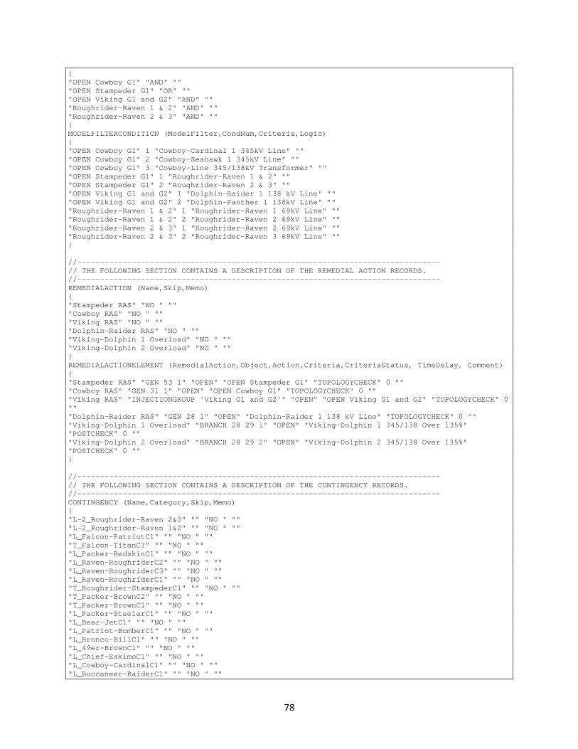
78
{ "OPEN Cowboy G1" "AND" "" "OPEN Stampeder G1" "OR" "" "OPEN Viking G1 and G2" "AND" "" "Roughrider-Raven 1 & 2" "AND" "" "Roughrider-Raven 2 & 3" "AND" "" } MODELFILTERCONDITION (ModelFilter,CondNum,Criteria,Logic) { "OPEN Cowboy G1" 1 "Cowboy-Cardinal 1 345kV Line" "" "OPEN Cowboy G1" 2 "Cowboy-Seahawk 1 345kV Line" "" "OPEN Cowboy G1" 3 "Cowboy-Line 345/138kV Transformer" "" "OPEN Stampeder G1" 1 "Roughrider-Raven 1 & 2" "" "OPEN Stampeder G1" 2 "Roughrider-Raven 2 & 3" "" "OPEN Viking G1 and G2" 1 "Dolphin-Raider 1 138 kV Line" "" "OPEN Viking G1 and G2" 2 "Dolphin-Panther 1 138kV Line" "" "Roughrider-Raven 1 & 2" 1 "Roughrider-Raven 1 69kV Line" "" "Roughrider-Raven 1 & 2" 2 "Roughrider-Raven 2 69kV Line" "" "Roughrider-Raven 2 & 3" 1 "Roughrider-Raven 2 69kV Line" "" "Roughrider-Raven 2 & 3" 2 "Roughrider-Raven 3 69kV Line" "" } //-------------------------------------------------------------------------------- // THE FOLLOWING SECTION CONTAINS A DESCRIPTION OF THE REMEDIAL ACTION RECORDS. //-------------------------------------------------------------------------------- REMEDIALACTION (Name,Skip,Memo) { "Stampeder RAS" "NO " "" "Cowboy RAS" "NO " "" "Viking RAS" "NO " "" "Dolphin-Raider RAS" "NO " "" "Viking-Dolphin 1 Overload" "NO " "" "Viking-Dolphin 2 Overload" "NO " "" } REMEDIALACTIONELEMENT (RemedialAction,Object,Action,Criteria,CriteriaStatus, TimeDelay, Comment) { "Stampeder RAS" "GEN 53 1" "OPEN" "OPEN Stampeder G1" "TOPOLOGYCHECK" 0 "" "Cowboy RAS" "GEN 31 1" "OPEN" "OPEN Cowboy G1" "TOPOLOGYCHECK" 0 "" "Viking RAS" "INJECTIONGROUP 'Viking G1 and G2'" "OPEN" "OPEN Viking G1 and G2" "TOPOLOGYCHECK" 0 "" "Dolphin-Raider RAS" "GEN 28 1" "OPEN" "Dolphin-Raider 1 138 kV Line" "TOPOLOGYCHECK" 0 "" "Viking-Dolphin 1 Overload" "BRANCH 28 29 1" "OPEN" "Viking-Dolphin 1 345/138 Over 135%" "POSTCHECK" 0 "" "Viking-Dolphin 2 Overload" "BRANCH 28 29 2" "OPEN" "Viking-Dolphin 2 345/138 Over 135%" "POSTCHECK" 0 "" } //-------------------------------------------------------------------------------- // THE FOLLOWING SECTION CONTAINS A DESCRIPTION OF THE CONTINGENCY RECORDS. //-------------------------------------------------------------------------------- CONTINGENCY (Name,Category,Skip,Memo) { "L-2_Roughrider-Raven 2&3" "" "NO " "" "L-2_Roughrider-Raven 1&2" "" "NO " "" "L_Falcon-PatriotC1" "" "NO " "" "T_Falcon-TitanC1" "" "NO " "" "L_Packer-RedskinC1" "" "NO " "" "L_Raven-RoughriderC2" "" "NO " "" "L_Raven-RoughriderC3" "" "NO " "" "L_Raven-RoughriderC1" "" "NO " "" "T_Roughrider-StampederC1" "" "NO " "" "T_Packer-BrownC2" "" "NO " "" "T_Packer-BrownC1" "" "NO " "" "L_Packer-SteelerC1" "" "NO " "" "L_Bear-JetC1" "" "NO " "" "L_Patriot-BomberC1" "" "NO " "" "L_Bronco-BillC1" "" "NO " "" "L_49er-BrownC1" "" "NO " "" "L_Chief-EskimoC1" "" "NO " "" "L_Cowboy-CardinalC1" "" "NO " "" "L_Buccaneer-RaiderC1" "" "NO " ""

79
"L_Packer-ColtC1" "" "NO " "" "L_Lion-TitanC1" "" "NO " "" "L_Bengal-SteelerC1" "" "NO " "" "L_Colt-GiantC1" "" "NO " "" "L_Redskin-EagleC1" "" "NO " "" "L_Redskin-EagleC2" "" "NO " "" "L_Bear-ChargerC1" "" "NO " "" "L_Roughrider-BomberC1" "" "NO " "" "L_Bear-EskimoC1" "" "NO " "" "L_Saint-JetC1" "" "NO " "" "L_Saint-JetC2" "" "NO " "" "L_Bronco-RedskinC1" "" "NO " "" "L_Raven-RamC1" "" "NO " "" "L_Dolphin-RaiderC1" "" "NO " "" "L_Panther-DolphinC1" "" "NO " "" "L_Raven-BengalC1" "" "NO " "" "L_Cowboy-VikingC1" "" "NO " "" "L_Argonaut-DolphinC1" "" "NO " "" "L_Buccaneer-PantherC1" "" "NO " "" "T_Viking-DolphinC2" "" "NO " "" "T_Lion-CowboyC1" "" "NO " "" "L_Texan-BillC1" "" "NO " "" "T_Chief-PantherC1" "" "NO " "" "T_Viking-DolphinC1" "" "NO " "" "L_Ram-BillC1" "" "NO " "" "L_Lion-ArgonautC1" "" "NO " "" "T_Titan-CardinalC1" "" "NO " "" "T_Titan-CardinalC2" "" "NO " "" "L_Titan-BrownC1" "" "NO " "" "L_Titan-JaguarC1" "" "NO " "" "T_Bill-RaiderC1" "" "NO " "" "T_Bill-RaiderC2" "" "NO " "" "T_Jet-JaguarC1" "" "NO " "" "L_Jaguar-StampederC1" "" "NO " "" "L_Jet-RoughriderC1" "" "NO " "" "L_Texan-ChargerC1" "" "NO " "" "L_Falcon-GiantC1" "" "NO " "" "L-2_Dolphin-Panther/Dolphin-Raider" "" "NO " "" "L_49er-RaiderC1" "" "NO " "" "T_Seahawk-BrownC1" "" "NO " "" "L-2_Cowboy-Cardinal\Cowboy-Seahawk" "" "NO " "" "L_Seahawk-CowboyC1" "" "NO " "" } CONTINGENCYELEMENT (Contingency,Object,Action,Criteria,CriteriaStatus,TimeDelay, Comment) { "L-2_Roughrider-Raven 2&3" "BRANCH 15 54 2" "OPEN" "" "CHECK" 0 "" "L-2_Roughrider-Raven 2&3" "BRANCH 15 54 3" "OPEN" "" "CHECK" 0 "" "L-2_Roughrider-Raven 1&2" "BRANCH 15 54 1" "OPEN" "" "CHECK" 0 "" "L-2_Roughrider-Raven 1&2" "BRANCH 15 54 2" "OPEN" "" "CHECK" 0 "" "L_Falcon-PatriotC1" "BRANCH 10 13 1" "OPEN" "" "CHECK" 0 "" "T_Falcon-TitanC1" "BRANCH 10 39 1" "OPEN" "" "CHECK" 0 "" "L_Packer-RedskinC1" "BRANCH 12 18 1" "OPEN" "" "CHECK" 0 "" "L_Raven-RoughriderC2" "BRANCH 15 54 2" "OPEN" "" "CHECK" 0 "" "L_Raven-RoughriderC3" "BRANCH 15 54 3" "OPEN" "" "CHECK" 0 "" "L_Raven-RoughriderC1" "BRANCH 15 54 1" "OPEN" "" "CHECK" 0 "" "T_Roughrider-StampederC1" "BRANCH 54 53 1" "OPEN" "" "CHECK" 0 "" "T_Packer-BrownC2" "BRANCH 12 40 2" "OPEN" "" "CHECK" 0 "" "T_Packer-BrownC1" "BRANCH 12 40 1" "OPEN" "" "CHECK" 0 "" "L_Packer-SteelerC1" "BRANCH 12 27 1" "OPEN" "" "CHECK" 0 "" "L_Bear-JetC1" "BRANCH 20 48 1" "OPEN" "" "CHECK" 0 "" "L_Patriot-BomberC1" "BRANCH 13 55 1" "OPEN" "" "CHECK" 0 "" "L_Bronco-BillC1" "BRANCH 5 44 1" "OPEN" "" "CHECK" 0 "" "L_49er-BrownC1" "BRANCH 3 40 1" "OPEN" "" "CHECK" 0 "" "L_Chief-EskimoC1" "BRANCH 33 50 1" "OPEN" "" "CHECK" 0 "" "L_Cowboy-CardinalC1" "BRANCH 31 38 1" "OPEN" "" "CHECK" 0 "" "L_Buccaneer-RaiderC1" "BRANCH 30 41 1" "OPEN" "" "CHECK" 0 "" "L_Packer-ColtC1" "BRANCH 12 17 1" "OPEN" "" "CHECK" 0 "" "L_Lion-TitanC1" "BRANCH 35 39 1" "OPEN" "" "CHECK" 0 "" "L_Bengal-SteelerC1" "BRANCH 16 27 1" "OPEN" "" "CHECK" 0 "" "L_Colt-GiantC1" "BRANCH 17 19 1" "OPEN" "" "CHECK" 0 "" "L_Redskin-EagleC1" "BRANCH 18 37 1" "OPEN" "" "CHECK" 0 ""

80
"L_Redskin-EagleC2" "BRANCH 18 37 2" "OPEN" "" "CHECK" 0 "" "L_Bear-ChargerC1" "BRANCH 20 34 1" "OPEN" "" "CHECK" 0 "" "L_Roughrider-BomberC1" "BRANCH 54 55 1" "OPEN" "" "CHECK" 0 "" "L_Bear-EskimoC1" "BRANCH 20 50 1" "OPEN" "" "CHECK" 0 "" "L_Saint-JetC1" "BRANCH 21 48 1" "OPEN" "" "CHECK" 0 "" "L_Saint-JetC2" "BRANCH 21 48 2" "OPEN" "" "CHECK" 0 "" "L_Bronco-RedskinC1" "BRANCH 5 18 1" "OPEN" "" "CHECK" 0 "" "L_Raven-RamC1" "BRANCH 15 24 1" "OPEN" "" "CHECK" 0 "" "L_Dolphin-RaiderC1" "BRANCH 29 41 1" "OPEN" "" "CHECK" 0 "" "L_Panther-DolphinC1" "BRANCH 32 29 1" "OPEN" "" "CHECK" 0 "" "L_Raven-BengalC1" "BRANCH 15 16 1" "OPEN" "" "CHECK" 0 "" "L_Cowboy-VikingC1" "BRANCH 31 28 1" "OPEN" "" "CHECK" 0 "" "L_Argonaut-DolphinC1" "BRANCH 56 29 1" "OPEN" "" "CHECK" 0 "" "L_Buccaneer-PantherC1" "BRANCH 30 32 1" "OPEN" "" "CHECK" 0 "" "T_Viking-DolphinC2" "BRANCH 28 29 2" "OPEN" "" "CHECK" 0 "" "T_Lion-CowboyC1" "BRANCH 35 31 1" "OPEN" "" "CHECK" 0 "" "L_Texan-BillC1" "BRANCH 14 44 1" "OPEN" "" "CHECK" 0 "" "T_Chief-PantherC1" "BRANCH 33 32 1" "OPEN" "" "CHECK" 0 "" "T_Viking-DolphinC1" "BRANCH 28 29 1" "OPEN" "" "CHECK" 0 "" "L_Ram-BillC1" "BRANCH 24 44 1" "OPEN" "" "CHECK" 0 "" "L_Lion-ArgonautC1" "BRANCH 35 56 1" "OPEN" "" "CHECK" 0 "" "T_Titan-CardinalC1" "BRANCH 39 38 1" "OPEN" "" "CHECK" 0 "" "T_Titan-CardinalC2" "BRANCH 39 38 2" "OPEN" "" "CHECK" 0 "" "L_Titan-BrownC1" "BRANCH 39 40 1" "OPEN" "" "CHECK" 0 "" "L_Titan-JaguarC1" "BRANCH 39 47 1" "OPEN" "" "CHECK" 0 "" "T_Bill-RaiderC1" "BRANCH 44 41 1" "OPEN" "" "CHECK" 0 "" "T_Bill-RaiderC2" "BRANCH 44 41 2" "OPEN" "" "CHECK" 0 "" "T_Jet-JaguarC1" "BRANCH 48 47 1" "OPEN" "" "CHECK" 0 "" "L_Jaguar-StampederC1" "BRANCH 47 53 1" "OPEN" "" "CHECK" 0 "" "L_Jet-RoughriderC1" "BRANCH 48 54 1" "OPEN" "" "CHECK" 0 "" "L_Texan-ChargerC1" "BRANCH 14 34 1" "OPEN" "" "CHECK" 0 "" "L_Falcon-GiantC1" "BRANCH 10 19 1" "OPEN" "" "CHECK" 0 "" "L-2_Dolphin-Panther/Dolphin-Raider" "BRANCH 32 29 1" "OPEN" "" "CHECK" 0 "" "L-2_Dolphin-Panther/Dolphin-Raider" "BRANCH 29 41 1" "OPEN" "" "CHECK" 0 "" "L_49er-RaiderC1" "BRANCH 3 41 1" "OPEN" "" "CHECK" 0 "" "T_Seahawk-BrownC1" "BRANCH 1 40 1" "OPEN" "" "CHECK" 0 "" "L-2_Cowboy-Cardinal\Cowboy-Seahawk" "BRANCH 31 38 1" "OPEN" "" "CHECK" 0 "" "L-2_Cowboy-Cardinal\Cowboy-Seahawk" "BRANCH 1 31 1" "OPEN" "" "CHECK" 0 "" "L_Seahawk-CowboyC1" "BRANCH 1 31 1" "OPEN" "" "CHECK" 0 "" }