Embed Size (px)
Citation preview

Current Research in Earth Sciences, Bulletin 253, part 2 (http://www.kgs.ku.edu/Current/2007/Harbaugh/index.html)
Reconstructing Late Cenozoic Stream Gradients from High-level Chert Gravels, Central Eastern Kansas 1
Reconstructing Late Cenozoic Stream Gradients from High-level Chert Gravels in Central Eastern Kansas
John W. Harbaugh1, Daniel F. Merriam2, and Hugh H. Howard3
1Department of Geological Sciences, Stanford University, Palo Alto, CA 94305-21152Former Senior Scientist (retired 1997), Kansas Geological Survey, University of Kansas, Lawrence, KS 66047-3724
3Earth Science, American River College, Sacramento, CA 95841
Abstract
Interpreting the evolution of Kansas’ landscape east of the Flint Hills provides major challenges. In the Neogene (late Tertiary) and perhaps part of the Pleistocene, streams transported a variety of sedimentary materials, including chert gravels derived from the Flint Hills. Gentle intermittent uplift stimulated the stream system to cut down, locally removing and reworking the gravels to create stream-terrace deposits that consist mostly of chert pebbles, which now lie well above the fl oodplains of modern streams. By correlating the elevations of these gravels, the gradients of the trunk streams that deposited them can be reconstructed. Interestingly, these ancient streams fl owed southeast at a little more than a foot per mile (0.2 m/km), roughly the same as the gradient of the trunk streams in the region today. The evolving landscape in eastern Kansas also has been strongly infl uenced by an extensive network of fractures that is widespread in the midcontinent region and may be worldwide in extent. In northeastern Kansas, glaciation during the Pleistocene disrupted the southeasterly drainage and established the present location of the Kansas River. South of the Kansas River and its immediate tributaries, however, the general southeasterly drainage has been preserved. We have made use of the wealth of topographic-elevation data now available in digital form known as DEMs or digital elevation models. Coupled with GIS procedures, the DEMs helped link the mapped distribution of chert gravels with hypothetical fi tted surfaces that represent ancient stream gradients. Furthermore, DEM data placed in shaded-relief map form emphasize the infl uence of fractures in evolution of the drainage system.
Introduction
Kansas has interesting topography. Far from being a “featureless plain” as characterized by a few writers, Kansas' scenery is varied and intricate, and eastern Kansas particularly so. When considered in detail, the topography in eastern Kansas is astoundingly complex. This study focuses on an area of about 10,000 mi2 (25,900 km2) in eastern Kansas (fi g. 1) that spans parts of several major drainage systems including (from north to south) the Kansas, Marais des Cygnes, Neosho, Verdigris, and Fall rivers (fi g. 2A) and covers parts of three physiographic provinces, namely the Glaciated Area, Flint Hills, and Osage Cuestas (fi g. 2B). The study area consists of two parts: 1) a smaller “experimental area” and 2) an extension of the area to the west and north to form the “overall area” as defi ned in fi g. 3. Recent technology has provided new ways of looking at topography that stem from digitizing of topographic
FIGURE 1—Index map showing location of the study area in eastern Kansas and its relation to the Flint Hills. The study area has been divided into “large” quadrangles labeled from A to P, which in turn are composed of 7 1/2-min topographic quadrangles identifi ed in fi g. 3. The “experimental area” includes large quadrangles A through I and denotes where experiments described have been conducted. “Overall area” includes quadrangles A though P and incorporates “extended area” to the west and north consisting of quadrangles J through P. Lineaments have been analyzed throughout the overall area.
maps. Kansas is covered completely by detailed, reliable 7.5-min topographic maps that have been produced by the U.S.

Current Research in Earth Sciences, Bulletin 253, part 2 (http://www.kgs.ku.edu/Current/2007/Harbaugh/index.html)
Reconstructing Late Cenozoic Stream Gradients from High-level Chert Gravels, Central Eastern Kansas 2
FIGURE 2—A, Major streams and tributaries in Kansas. In eastern Kansas, drainage is toward the east and southeast. B, Physiographic provinces in Kansas. Study area includes part of Glaciated Region, Flint Hills, and Osage Cuestas.
A
Geological Survey in the past 55 years. These maps have been made by analog methods from stereoscopic coverage with aerial photographs. More recently, data represented as contour lines on the maps have been placed in digital form in a series of pixels, each 30 m square. The elevation of the land surface in each pixel has been estimated from the contour lines and recorded in meters above sea level to the nearest whole meter. The digitization of the topography has
been done under contract to the Department of Defense, and the resulting fi les are known either as digital elevation models (DEMs) or as digital terrain models (DTMs). The DEM fi les are organized by topographic quadrangles, and those in the study area are identifi ed in fi g. 3. Placing topographic maps in digital form has many advantages. One major advantage is that the maps can be viewed in different ways. Instead of conventional contour
Jefferson
Leaven-worth
Wyan-dotte
Atchison
BrownDoniphan
Jackson
Shawnee
Douglas JohnsonMiamiFranklin
Osage
Lyon
Wabaunsee
NemahaMarshall
Pottawatomie
Morris
Anderson Linn
Bourbon
CrawfordCherokeeLabette
Neosho
Allen
Mont-gomery
Woodson
Coffey
Riley
GearyDickinson
Clay
WashingtonRepublic
Cloud
Ottawa
Saline
McPherson Marion
Elk
Chase
Harvey
Sedgwick
Greenwood
Chautauqua
CowleySumner
Harper
JewellSmith
Osborne Mitchell
Phillips
Rooks
Ellis Russell
Barton
GrahamSheridan
Decatur NortonRawlins
Kingman
Reno
Stafford
Rice
Ellsworth
LincolnTrego
Ness
Barber
Pratt
Edwards
Kiowa
Comanche
Clark
Ford
Hodgeman
Gray
Cheyenne
Sherman Thomas
LoganWallaceGove
LaneScottWichitaGreeley
Hamilton Kearny Finney
MeadeHaskellSewardStevensMorton
Stanton Grant
Pawnee
Butler
Rush
Wilson
High Plains
Smoky Hills
Arkansas River Lowlands
Wellington–McPherson LowlandsGlaciated Region
Osage Cuestas
Flint Hills Uplands
Ozark Plateau
Cherokee Lowlands
Chautauqua Hills
Red Hills
80 mi
120 km
0
0
N
B

Current Research in Earth Sciences, Bulletin 253, part 2 (http://www.kgs.ku.edu/Current/2007/Harbaugh/index.html)
Reconstructing Late Cenozoic Stream Gradients from High-level Chert Gravels, Central Eastern Kansas 3
FIGURE 3—Index map of topographic quadrangles in overall study area.
lines, variations in elevation can be viewed as bands of color, or even more usefully, in the form of shaded-relief (hillshade) maps. Although the data represented in shaded-relief maps have been derived from conventional topographic contour maps, the shaded-relief maps may provide more geologically useful information than the contour maps on which they are based. A second major advantage of DEMs is that they can be manipulated by computer using the powerful computing
procedures provided by geographic information systems (GIS). Because all the information is in digital form, different topographic surfaces can be combined or contrasted digitally, and the details of the surfaces analyzed numerically. Using software commercially known as ArcInfo© developed by the Environmental Systems Research Institute (ESRI), of Redlands, California, we combined information from DEMs with digitized geological mapping of the high-level chert gravels.
Geological Background Overall, the geology of Kansas is relatively simple. It consists of a “layer-cake” sequence of sedimentary rocks
as well as unconsolidated sediments ranging in age from Cambrian to Holocene, which overlie the Precambrian

Current Research in Earth Sciences, Bulletin 253, part 2 (http://www.kgs.ku.edu/Current/2007/Harbaugh/index.html)
Reconstructing Late Cenozoic Stream Gradients from High-level Chert Gravels, Central Eastern Kansas 4
FIGURE 4—Schematic stratigraphic section for eastern Kansas. Rocks older than Mississippian are known in subsurface only.
crystalline basement (Merriam, 2006; fi g. 4). The topography in eastern Kansas refl ects this simplistic geology and has been shaped by erosion of the sequence of alternating thin beds of Permian–Pennsylvanian sedimentary rocks that dip gently to the west. Limestone units underlain by shales and sandstones tend to form cuestas that face eastward, with
gentle dip slopes to the west. So, traversing the stratigraphic section from west to east is similar to going through pages of a book starting at the beginning in the west and proceeding to the oldest (the end) in the east. The northern part of the study area has been glaciated, so there the Permian–Pennsylvanian units tend to be concealed by Pleistocene glacial deposits. Details of the topography, however, are not as simple as this brief description might imply. South of the glacial boundary, the westerly tilted Permian–Pennsylvanian beds have been shaped by a complex history of fl uvial erosion as streams have cut through the generally north-south-trending cuestas. Although the topography is not rugged in the sense of mountainous terrain, nevertheless, the slopes are steep in places so that the local topographic relief can be considerable; the relief in a lateral distance of a km or two may be as much as 60 or 70 m. In places over a span of 6 or 8 km, the relief may be as much as 150 m. Clearly, eastern Kansas is not a featureless plain. Figure 5 is a shaded-relief map that attests to the overall complexity of the topography of the study area. The trunk streams fl ow either to the east or southeast (fi g. 2A). We may presume that overall drainage directions to the east and southeast have prevailed for a long time, perhaps for much of the Cenozoic, although there have been important changes in the drainage system during this time. Notably, the course of the Kansas River, which is the largest river in the area and a major tributary of the Missouri River, and in turn of the Mississippi River, was infl uenced by glaciation. Most of the area south of the Kansas River in eastern Kansas, however, has not been glaciated (fi g. 2B). The streams in eastern Kansas have evolved during a considerable length of time, perhaps for as much as fi ve or ten million years or even longer. Whatever span of time is presumed, however, is a generalized guess for which we have limited evidence. In glaciated northeast Kansas, however, the topographic details may be more recent.
Use of High-level Chert Gravels to Document Gradients of Ancestral Streams
The term “high-level” chert gravel here connotes gravel deposits that are topographically higher than the deposits being formed at present by streams or that reside in modern low-level stream terraces. The locations of the high-level gravels in the “experimental” area are shown in fi g. 6. Of course, the present streams transport chert pebbles (among other materials) and locally extensive gravel deposits occur in modern streams. Importantly, the properties of the modern streams and perhaps their fl oodplains may be similar in general form to those of the ancient streams that deposited the high-level chert gravels. The high-level chert gravels provide evidence of the gradients of ancestral streams. As described in a related article by Merriam and Harbaugh (2004), the chert fragments have been derived through weathering of chert-bearing Permian limestones that crop out in the Flint Hills. The chert,
being relatively insoluble by comparison with the limestone, tends to be concentrated in soils and lag gravels before being transported. Prolonged solution of the limestones has provided abundant chert-bearing gravel for transport by east-fl owing ancient streams that were ancestral to the present streams. Although they consist mostly of chert, some of the high-level gravel deposits have a matrix of reddish clay, suggesting that clay may have been part of the lag deposits and transported along with the chert fragments. The chert fragments in the present high-level gravels were assuredly derived from Permian limestones in the Flint Hills and not from limestones in the Pennsylvanian sequence east of the Flint Hills over which the gravels have been deposited. The Pennsylvanian limestones contain relatively little chert, whereas the Permian limestones in the Flint Hills generally have a high proportion of chert (Merriam
GeneralStratigraphic
Column
Age
Thickness/ft
Rock Type
Quaternary 0 - 30 sand and siltTertiary 0 - 20 chert gravel
Permian-Pennsylvanian
0 - 2000
Alternating thick shale,lenticular sandstone, andthin limestone in cyclicpattern.
Mississippian-Devonian
200 - 450(0 - 100)
Mainly limestone withsome dolomite and shale,cherty in places. Uppersurface is karsted. Blackshale at base (Devonian).
Cambrian-Ordovician
700 - 950
Mainly dolomite with somelimestone. Sandstone atbase (Cambrian). Uppersurface karsted; lowersurface uneven.
Granite/rhyolite crystallineswith some metasediments.Faulted in block pattern1.1 - 1.4 Ga.
Precambrian

Current Research in Earth Sciences, Bulletin 253, part 2 (http://www.kgs.ku.edu/Current/2007/Harbaugh/index.html)
Reconstructing Late Cenozoic Stream Gradients from High-level Chert Gravels, Central Eastern Kansas 5
and Harbaugh, 2004, fi g. 4). Furthermore, some of the fusulinids in the chert fragments are Permian in age, and not Pennsylvanian (Merriam, 1963).
Attributing the high-level chert gravels to deposition by streams is problematic. First, even in the best exposures such as pits where they have been quarried for road material, the
FIGURE 5—Mosaic of DEM fi les in study area represented in shaded-relief form. Angle of sun is 45° from horizon, and sun shines from azimuth angle of N45°W. Pronounced variations in quality of DEM fi les are evident from quadrangle to quadrangle. Files for some quadrangles yield sharp shaded-relief images, whereas others are blurred. Differences stem from variations in digitizing work carried out by contractors for the U.S. Department of Defense. DEM information has served as the principal source of elevations for experiments described here, as well as for mapping of lineaments. White lines denote outline of “experimental” area within “overall” study area.

Current Research in Earth Sciences, Bulletin 253, part 2 (http://www.kgs.ku.edu/Current/2007/Harbaugh/index.html)
Reconstructing Late Cenozoic Stream Gradients from High-level Chert Gravels, Central Eastern Kansas 6
FIGURE 6—Mapped distribution of high-level chert gravels mapped in the “experimental area” superimposed on the shaded-relief map.
gravels lack the most rudimentary aspects of stratifi cation, including cross stratifi cation. The sizes and shapes of the chert particles are also puzzling. Most exhibit a degree of rounding, but many are
relatively angular (Merriam and Harbaugh, 2004, fi g. 5), and the gravel deposits generally are poorly sorted by size, with large and small particles jumbled together in disorder, the largest being about 15 cm across. Thus, although the high-

Current Research in Earth Sciences, Bulletin 253, part 2 (http://www.kgs.ku.edu/Current/2007/Harbaugh/index.html)
Reconstructing Late Cenozoic Stream Gradients from High-level Chert Gravels, Central Eastern Kansas 7
level chert gravels may not be typical stream-gravel deposits, it is diffi cult to devise an alternate means by which they might have been transported. Transport of chert-bearing gravels from the Flint Hills by east- or southeast-fl owing streams has been going on for a long time. It is occurring today, and presumably has taken place during the Quaternary (Pleistocene) and Tertiary (Neogene), and perhaps even earlier. The time span is problematical, for there is no fi rm dating method for these deposits. It is reasonable, however, to presume that streams fl owing over low gradients toward the east and southeast were part of an ancestral drainage system that deposited the gravels, and the upland gravels that we see today are remnants left high and dry as the streams cut down. Mapping of the high-level chert gravels suggests that there are at least two separate levels of high-level chert gravels, namely a younger “lower” high-level chert gravel, and an older “upper” high-level chert gravel (Aber, 1992). In places, the remnants of these gravels are a meter or more thick, although the thicknesses are extremely variable and are diffi cult to measure because of poor exposures. The age difference between the “upper” and “lower” gravels is problematical, but presumably the “lower” gravels were deposited considerably later than the “upper” gravels. Some of the “upper” high-level chert gravels occur on the tops of hills on interstream divides. Although these high-level chert gravels have been largely removed by subsequent erosion, they are presumed to have once been more widespread in eastern Kansas. Furthermore, older and higher high-level chert gravel deposits may have been present, but if they existed, no remnants have been identifi ed. Given that the gravels were deposited by streams, however, it is unlikely that they formed sheetlike deposits that extended more or less continuously over large areas, and we may presume that they formed along successive fl oodplains of ancient streams. An assumption that needs to be weighed carefully involves the three-dimensional positions of the chert gravels. If they are fl uvial deposits, the surfaces on which they rest
must be ancient land surfaces, or more properly, they must be the bedrock surfaces over which streams fl owed that deposited the gravels. This is a critical assumption. Wherever the high-level chert gravels have been preserved, remnants of the old bedrock surfaces also have been preserved. If these remnants can be linked appropriately, the gradient or general slope of the ancient landscape over which the ancient streams fl owed can be reconstructed. However, the fact that only scattered remnants of these ancient fl uvial deposits have been preserved is problematical. The present-day geographic distribution in the experimental area (fi g. 6) suggests that the gravels probably were more widespread in the past, so the remnants preserved today probably represent only a portion of the gravel's former aggregate areal extent. We may presume, however, that the ancient deposits formed on low-lying surfaces along ancient drainage ways and did not form widespread blanket deposits continuous over large areas. Because the high-level chert gravel deposits are relatively small in area and vegetation cover is extensive, it stands to reason that probably remnants of chert-gravel deposits that have not been located or mapped do exist. The sparse distribution of remnants of high-level chert gravels raises the question as to the effi cacy of the mapping. Could there be other remnants that are present but have not been detected in mapping? The answer is a guarded yes. The favorite places to look for chert fragments are on the tops of hills, in fi elds, or in ditches along roadsides. The gravels have been quarried for road material in places where they are thick, and of course old quarries are relatively easy to locate. The question is whether improved mapping would provide substantially more evidence. If more high-level chert deposits could be located, it would be useful to know about them. On the other hand, the conclusions reached here probably would not be seriously altered, although knowledge of more gravel deposits might enable us to refi ne our estimates of the ancient stream gradients and general directions of fl ow.
Reconstructing the Gradients
Mapping the elevations of the high-level chert gravels involves coordinating their locations with the DEM data. The elevations of high-level chert-gravel deposits of equivalent age must necessarily become progressively lower toward the southeast if southeastward-fl owing streams deposited them, suggesting that reconstruction of former stream gradients can be made with relative confi dence. We note that because data in the DEM fi les have been obtained by digitizing elevations from topographic maps, the elevation data in fi gs. 5, 10, and 11 are surrogates for conventional topographic maps, although they present information in different graphic form. Ascertaining old stream gradients involved repeated trials with different assumptions about the theoretical elevations and gradients of these ancient streams and
comparing them with the gradients and elevations of actual remnants of the gravels segregated into “upper” and “lower” gravels. The locations of the actual gravels are known from geologic mapping, and the DEM fi les provide their elevations. In a succession of trial-and-error GIS “experiments,” we generated theoretical surfaces on which the “upper” gravels could have been deposited and then located places where these theoretical gravels could accord with the present topography. We experimented with dozens of different gradients and slope directions until we eventually obtained a combination of gradient and slope that provides a best match between locations of the theoretical deposits and locations of actual deposits. We conducted a similar series of experiments for the “lower” gravels. In the end, we decided to represent the two theoretical surfaces with

Current Research in Earth Sciences, Bulletin 253, part 2 (http://www.kgs.ku.edu/Current/2007/Harbaugh/index.html)
Reconstructing Late Cenozoic Stream Gradients from High-level Chert Gravels, Central Eastern Kansas 8
FIGURE 7—Schematic diagrams illustrating fi tting of theoretical gravel deposit to actual high-level terrace-gravel deposits. Although no exact scale is implied, block diagrams represent an area about 40 km northwest-southeast with a topographic relief of about 60 m.
A, Late Tertiary: Progressive erosion has created a broad alluvial plain (green) on which a younger “lower” high-level gravel deposit is forming. Older “higher” high-level gravel deposit has been preserved in part and forms an alluvial terrace (red). B, Today’s topography (brown) on which remnants of lower and higher high-level gravel deposits (denoted by green and red) have been preserved. Modern alluvial plain is denoted by yellow. C, Today’s topography and remnants of actual higher high-level gravel deposits (red) to which a gently sloping plane (pink) representing base of theoretical gravel layer has been fi tted to coincide with elevation of actual deposits. (Note that lower high-level deposits (younger) are obscured because they lie beneath fi tted plane). Fitted plane is interpreted as restoration of gradient and position of alluvial plain on which actual higher high-level gravel deposits formed.
Today - sloping plane fitted to base of upper gravelsPreserved upper gravel
Towardmodern
Flint Hills
TowardancestralFlint Hills
Today
Pre-Pleistocenenorthwestsoutheast
Preservedupper gravel
Uppergravel
Preservedlower gravelModern floodplaindeposits
A
B
C
Lowergravel
Fitted plane slopingsoutheast
Current Research in Earth Sciences, Bulletin 253, part 2 (http://www.kgs.ku.edu/Current/2007/Harbaugh/index.html)
Reconstructing Late Cenozoic Stream Gradients from High-level Chert Gravels, Central Eastern Kansas 9
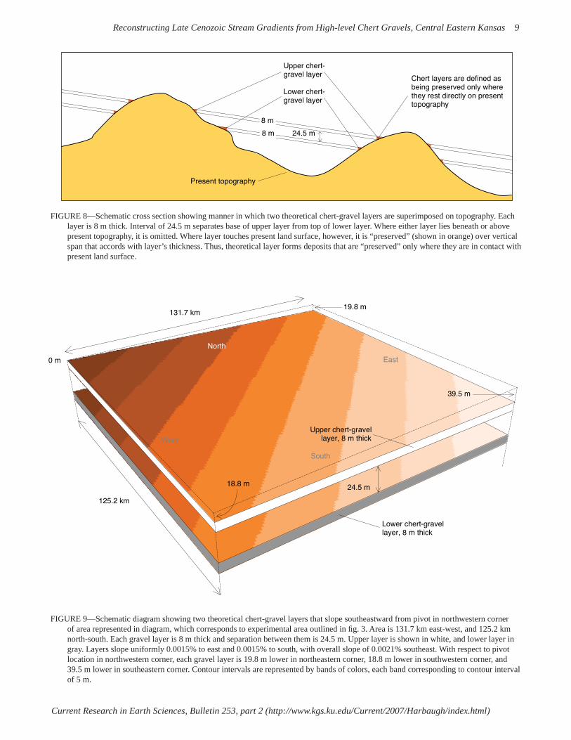
FIGURE 8—Schematic cross section showing manner in which two theoretical chert-gravel layers are superimposed on topography. Each layer is 8 m thick. Interval of 24.5 m separates base of upper layer from top of lower layer. Where either layer lies beneath or above present topography, it is omitted. Where layer touches present land surface, however, it is “preserved” (shown in orange) over vertical span that accords with layer’s thickness. Thus, theoretical layer forms deposits that are “preserved” only where they are in contact with present land surface.
FIGURE 9—Schematic diagram showing two theoretical chert-gravel layers that slope southeastward from pivot in northwestern corner of area represented in diagram, which corresponds to experimental area outlined in fi g. 3. Area is 131.7 km east-west, and 125.2 km north-south. Each gravel layer is 8 m thick and separation between them is 24.5 m. Upper layer is shown in white, and lower layer in gray. Layers slope uniformly 0.0015% to east and 0.0015% to south, with overall slope of 0.0021% southeast. With respect to pivot location in northwestern corner, each gravel layer is 19.8 m lower in northeastern corner, 18.8 m lower in southwestern corner, and 39.5 m lower in southeastern corner. Contour intervals are represented by bands of colors, each band corresponding to contour interval of 5 m.
Upper chert- gravel layer
Lower chert- gravel layer
Present topography
24.5 m
Chert layers are defined as being preserved only where they rest directly on present topography
8 m
8 m
South
West
North
131.7 km
0 m
24.5 m
Lower chert-gravel layer, 8 m thick
Upper chert-gravellayer, 8 m thick
18.8 m
19.8 m
39.5 m
East
125.2 km

Current Research in Earth Sciences, Bulletin 253, part 2 (http://www.kgs.ku.edu/Current/2007/Harbaugh/index.html)
Reconstructing Late Cenozoic Stream Gradients from High-level Chert Gravels, Central Eastern Kansas 10
two parallel planes separated by an interval of 24.5 m, thus providing identical stream gradients and slope directions for the hypothetical “upper” and “lower” gravels. The procedure employed in the experiments is simple in principle, although the GIS operations are challenging. The procedure is illustrated schematically in fi g. 7, which consists of three related block diagrams that show a hypothetical part of the study area. The upper diagram (fi g. 7A) represents the geologic past when the younger “lower” high-level chert-gravel deposit was being formed, whereas the older “higher” deposit was partially preserved as an extensive terrace deposit. Figure 7B represents the area today, with scattered remnants preserved of both the “upper” and “lower” deposits. Figure 7C also represents the area today, but differs in that a theoretical sloping plane has been fi tted to the base of the remnants of the “upper” deposit. The elevation, slope gradient, and slope direction of the fi tted plane are interpreted as approximations of the gently sloping alluvial plains on which the “upper” deposit was formed. As an end product of our experiments, the two theoretical gravel layers have been defi ned as bounded by planes that are parallel to each other (fi g. 8). The thickness of each layer and the interval between them were added to become part of the defi nition. Because the two layers are parallel, the slope gradient and slope direction are identical for the planes, so that the only other parameters needed are the elevations of the planes at the “pivot point” (fi g. 9) and the geographic coordinates of the pivot point. Given this information, the system of planes defi ning the upper and lower surfaces of each of the two layers is completely defi ned and GIS experiments with ArcInfo are feasible. As described in the Appendix using the GIS procedures employed in the study, entries for the parameters in experiments provide a high degree of fl exibility. Two separate slope angles, one with respect to north-south and the other with respect to east-west, are entered for each of the
theoretical gravel layers. This permits them to have separate slope gradients and slope directions if desired. Similarly, an individual thickness can be entered for each gravel layer. In keeping with this fl exibility, the elevation at the pivot point must be supplied for the base of each of layer, so that the two layers need not be parallel in experiments. In our experiments, various combinations of slope gradients, slope directions, thicknesses, separation intervals, and elevations at the pivot location were tried. The challenge was to determine what combination yielded the best accord between actual chert gravels and the theoretical surfaces. Although a simple objective, our study involved successive trials with a potentially vast number of possible combinations. Figures 8 and 9 illustrate the combination of assumptions that in the end yielded the best accord with the actual gravels. Selecting a pivot location is a key initial step. We placed it in the northwestern corner of the experimental area (fi g. 9) and then defi ned a “pivot elevation” for the base of each of the two hypothetical chert-gravel layers. Each plane slopes away from its pivot (alternatively, it could slope toward its pivot), so that the elevation of the plane at any geographic location depends on the elevation of the pivot and the plane's slope gradient and direction of slope. Thus established, the planes are completely defi ned no matter how far each is extended. Initially, we assumed that a single theoretical chert-gravel layer would suffi ce, but we soon concluded later that two layers, each of the same thickness, would be more suitable. Late in our experiments, for simplicity we assumed that the layers should be parallel, with one below the other as shown in fi gs. 8 and 9. The need for the two theoretical layers arose because of the large disparities in elevations of the actual gravel deposits, which required that a vertical interval between them be defi ned. Thus, each “numerical” experiment consisted of defi ning the parameters of the two theoretical gravel layers and then mapping where they would intersect the present-day land surface. Wherever the base of a theoretical gravel layer rested directly on the present surface, the layer was deemed to be “preserved.” However, wherever the top of the theoretical layer would have lain below the present land surface, that layer could never have been deposited there and would not be mapped. Similarly, wherever the base of a layer would lie above the present surface, the layer would have been removed by erosion if it formerly existed and would not be mapped. Thus, given these assumptions, either of the theoretical gravel layers will be preserved only where the layer rests directly on the present land surface. These determinations involve logic and numerical operations provided by the GIS system and are outlined in the Appendix. The objective in these experiments was to select the combination of slope gradients, slope directions, pivotal locations and elevations, and thicknesses of the theoretical layers and the spacing between them that will yield the best accord. The geographic distribution of the actual chert
TABLE 1—County and quadrangle geologic maps consulted for this study.
County Author and reference
Anderson Johnson, 1993 Butler Aber, 1994 Coffee Merriam, 1999a Cowley Bass, 1929 Franklin Ball and others, 1963 Lyon OʼConnor and others, 1953 Greenwood Merriam, 1998 Labette Bennison, 1998 Osage OʼConnor and others, 1955 Woodson Merriam, 1999b Wilson Wagner, 1995
Quadrangle Author and reference
Altoona Wagner, 1961 Fredonia Wagner, 1954

Current Research in Earth Sciences, Bulletin 253, part 2 (http://www.kgs.ku.edu/Current/2007/Harbaugh/index.html)
Reconstructing Late Cenozoic Stream Gradients from High-level Chert Gravels, Central Eastern Kansas 11
�
� �����
�����
�
�� ���� ���� ��
���� �� ���� �� ���� ��
������������������
���������������������
������
���
��
��
�
�
�
����� ����
���������������
���
������� ���
���������� ���
FIGURE 10—Present topography of experimental area (defi ned in fi g. 3) in which color contours defi ne variations in elevation. Sidebar shows ranges of elevations and corresponding elevations in meters above sea level.

Current Research in Earth Sciences, Bulletin 253, part 2 (http://www.kgs.ku.edu/Current/2007/Harbaugh/index.html)
Reconstructing Late Cenozoic Stream Gradients from High-level Chert Gravels, Central Eastern Kansas 12
FIGURE 11—Present topography of experimental area denoted by color contours as in fi g. 10, except that hillshading has been superimposed over colors. Additionally, geographic distribution of two theoretical gravel layers has been superimposed (white for upper layer, gray-brown for lower layer). Finally, distribution of actual high-level chert gravels that have been mapped is also superimposed (small patches of red along the current drainage).
�
� �����
�����
�
�� ���� ���� ��
���� �� ���� �� ���� ��
������������������
���������������������
������
���
��
��
�
�
�
����� ����
���������������
���
������� ���
���������� ���

Current Research in Earth Sciences, Bulletin 253, part 2 (http://www.kgs.ku.edu/Current/2007/Harbaugh/index.html)
Reconstructing Late Cenozoic Stream Gradients from High-level Chert Gravels, Central Eastern Kansas 13
TABLE 2—Geometrical properties of theoretical chert-gravel layers that best accord with actual high-level chert gravels.
Direction of slope S45oESlope gradient 0.0002145 (21cm/km or 14 inches/mi)Thickness of each theoretical layer 8 m (25 ft)Spacing between theoretical layers 24.5 m (80 ft)Location of pivot NW corner experimental area; 39°7'30" N lat, 96°37'30" W long
gravels is known from geologic mapping. Many sources of data were used in locating the chert gravels including fi eld investigations and mapping (D. F. Merriam, fi eld data and maps), previous published geological maps (table 1), publications, such as Kansas Geological Survey Bulletin on Kansas Pit and Quarries (Kulstad and Nixon, 1951), and Aber (1985, 1992), Davis (1957), Frye (1955), Frye and Walters (1950), Merriam (1986), and Wooster (1934). Kansas Geological Survey open-fi le reports and measured stratigraphic sections and U.S. Department of Agriculture, Natural Resources Conservation Service, soil surveys were referenced. The geographic distribution of the theoretical gravels was generated in the GIS experiments, and the degree of accord then was judged on the basis of how closely the actual and the theoretical deposits coincide when mapped. The experimental area's present landscape is represented with colors for contour intervals in fi g. 10. Figure 11, which uses the same color scheme for contour intervals, includes in addition the mapped distribution of the actual and the theoretical chert-gravel deposits. The best accord that we obtained is represented by fi g. 11. Figure 11 is similar to fi g. 10 in that color contours also represent differences in elevation, but there are important differences. In Figure 11, shaded relief has been superimposed over the bands of colors, causing moderate differences in the shades of color, although the same color scheme is used to represent elevations. Most notably in fi g. 11, the geographic distribution of the two theoretical gravel layers has been incorporated in the map. Where the theoretical gravel layers have been “preserved,” the colors representing elevations have been suppressed. The upper of the two theoretical gravels is denoted with white, and the lower in brown. Furthermore, when the geographic distribution of the actual chert gravels (fi g. 6) is superimposed, the test is the degree to which the theoretical chert gravels and the actual chert gravels coincide as mapped here.
Complete coincidence would be an abstract ideal, and at best in our experiments the degree of coincidence was from far from ideal. If the thickness of either or both theoretical layers was decreased, the theoretical remnants of course were less extensive and would vanish if they were decreased too much. By contrast, if their thicknesses were increased, the remnants would be more extensive, but the degree of coincidence would not necessarily be increased. After a large number of experiments in which many different combinations of pivot elevations, gradients, thicknesses, intervals, and slope directions were tried, those shown in fi gs. 8 and 9 were the best that we could determine, based on the degree of coincidence on the map in fi g. 11. The parameters of the theoretical chert layers are listed in table 2. The coincidence in fi g. 11 is far from perfect, but all things considered it is not bad. The biggest difference is that the geographical extent of the theoretical chert gravels is greater than the actual chert deposits that have been preserved. The correspondence might have been better if actual gravels that correspond to the overall general distribution of the theoretical gravels formerly existed and had been better preserved. Whatever the former areal extent of the actual gravels, much has been removed by erosion in the meantime. We realize that our assumptions about the two theoretical high-level chert gravels are drastic simplifi cations. The slopes of the surfaces on which they were deposited ideally should incorporate a gentle exponential decrease toward the southeast. Furthermore, the assumption that each theoretical deposit was 8 m thick exceeds the known maximum thickness of any of the actual remnants of the high-level gravels of about 6 m. Nevertheless, these and other simplifi cations seem reasonable. Adding assumptions and progressively increasing the trial-and-error modifi cations would have required more experimentation and likely would not have modifi ed our general interpretations. Do the parameters as listed provide approximations for the actual ancient chert gravels? If we accept some latitude, they probably do. So if we are reasonably correct, we then are faced with the task of explaining how stream systems in eastern Kansas evolved in which gravels were transported over gradients of little more than 20 cm per km, or a foot per mile. However, at least one signifi cant exception to the generalized southeasterly gradient exists. Aber (1997, fi g. 2) documents a gradient toward the southwest in Anderson County, in the southeastern part of the experimental area, suggesting that there might have been another drainage system entering the region from the north or northwest. We do not have an explanation for this seemingly aberrant drainage direction, unless it was a tributary to one of the ancestral streams that generally drained toward the southeast.

Current Research in Earth Sciences, Bulletin 253, part 2 (http://www.kgs.ku.edu/Current/2007/Harbaugh/index.html)
Reconstructing Late Cenozoic Stream Gradients from High-level Chert Gravels, Central Eastern Kansas 14
Infl uence of the Earth's Fine-scale Fracture System
Eastern Kansas has been affected to a surprising degree by subtle tectonic activity that has involved continued fracturing of the earth's crust (Merriam, 1963). The presence of the fractures in Kansas is not unique; for whatever their explanation, many are presumed to be geologically ancient. Many of these fractures have had profound infl uence on the evolution of the details of Kansas topography. We speak here of the so-called "fi ne-scale" fractures, whose presence has come to light only recently in Kansas through use of shaded-relief mapping of digitized elevation data in DTM fi les (Harbaugh and others, 2005). They can be observed in most parts of Kansas and are widely discernible in the midcontinent region. The relationship between fi ne-scale fractures and conventional joints and faults is poorly known. The infl uence of joints and fractures on the topography of Kansas has been cited by various authors, most notably by Ward (1968) and White (1990). We suspect, however, that fi ne-scale fractures discerned on shaded-relief maps are fundamentally different and instead may represent components of the overall structure of the earth's crust. The evidence for such a system of fi ne-scale fractures presently is based solely on their presumed effect on topography, and to our knowledge the fractures themselves have not been observed directly. If a widespread system of fi ne-scale fractures is subsequently confi rmed, it will be a signifi cant advance in structural geology. The term "fi ne-scale" is a relative term. Fractures (including faults) in the earth's crust range over a wide range of scales. Some extend for tens or hundreds of kilometers, whereas others are observable at hand-specimen or thin-section scales. The term "fi ne-scale"" is used in this context to denote fractures that are smaller than the scale of tectonic features of crustal importance, but connotes a scale substantially larger than the scale of features such as joints observed at an outcrop. In Kansas and the midcontinent region, at least, the fi ne-scale fractures are pervasive. Measurements in Kansas indicate that they generally occur in several distinctively oriented sets. Where fracture sets are well defi ned, parallel fractures are spaced about 250 to 400 m apart, but where they are less well defi ned, it is diffi cult to measure the spacing between them. Although the importance of these fi ne-scale fractures seems to have been only recently appreciated, indirect references to subtle linear features that affect soil color or topography have been noted for many decades. We may suspect, however, that fi ne-scale fractures are present worldwide and have had large infl uence on the evolution of the topography in many regions. We can speculate that fi ne-scale fractures as well as other fractures whose presence is observed at the earth's surface, stem from fractures in the earth's rigid basement that have been propagated all the way to the surface through the overlying sedimentary sequence. For the most part, the fractures are not faults, at least not faults in the ordinary geological sense with perceptible vertical displacement.
Instead, the fractures may involve only small vertical displacements in which the two sides of a fracture may move alternately upward and downward relative to each other over distances of perhaps a few centimeters, without creating an aggregate perceptible displacement. Thus, they seem not to be faults because signifi cant vertical displacement would have been detected long ago. Lineaments have been of interest for decades. Many are discernible especially on Landsat imagery (DuBois, 1978; McCauley and others, 1978: McCauley, 1988). Also faults and fractures have been mapped and measured as well as inferring them from topography and drainage patterns. Geophysical techniques also have been interpreted in light of alignments (Yarger, 1983; Lam, 1987). Recently Merriam and Davis (in press) made a statistical study of these directional data in the U.S. midcontinent, noting that three trends are dominant: northeast, east-northeast, and northwest. Here we need to make the distinction between "fractures" and "lineaments." We regard fractures in the present context as controlling infl uences of the presence of features perceived as lineaments. We cannot see the fractures (at least not on shaded-relief maps), but we can see lineaments. Lineaments are usually subtle features that are more or less linear in extent and presumably do not represent faults with readily observable vertical displacement. On shaded-relief maps employed here (fi gs. 5 and 6, and fi gs. 11–13), perception of the lineaments stems solely from topographic features defi ned by differences in elevation in DEM fi les. No "tonal anomalies" that refl ect differences in soil color or vegetation as seen usually on aerial photographs or Landsat images are present. An immediate question is how could fractures have this much infl uence? Are these fractures actually faults along which slight vertical displacement has gone unrecognized? However, if they are faults, they must have scant vertical displacement, although alternatively they might have substantial lateral displacement that would be diffi cult to detect. So what are they? They seem to be fractures with very little, if any, displacement, but they nevertheless have had huge infl uence on the evolution of the landscape. What could cause them? We suggest that they are likely to be components of a fundamental fracture system that affects much or all of the earth's crust. We may speculate about their origins. One widely suggested hypothesis is that they refl ect continuing fl exure of the crust in response to the tidal cycles. In other words, the fl exures are the counterpart of the solid earth as it responds to the tides, although the responses are very different than the tidal responses of the sea. Another view is that the fractures may stem from subtle back-and-forth tectonic tilting of the crust as it responds to gentle upwarping and downwarping on a regional basis, although the cycles of back-and-forth tilting would necessarily be vastly longer than the twice-daily cycle of the tides. Nevertheless, whatever the cause and the length of its

Current Research in Earth Sciences, Bulletin 253, part 2 (http://www.kgs.ku.edu/Current/2007/Harbaugh/index.html)
Reconstructing Late Cenozoic Stream Gradients from High-level Chert Gravels, Central Eastern Kansas 15
� � �
� � �
� �
�
�
� � �
�
� ����
����
�
���������������������������
������������������������������������ �� ���� ���� ��
���� �� ���� �� ���� ��
������������������
���������������������
������
���
���
������
���������� ���
��
��
�
�
��
�
����
������
�������
��
����� ����
���������������
���
������� ���
� � �
� ! "�
# $ � %
� & ' (
FIGURE 12—Shaded-relief mosaic for entire area (fi g. 1) on which lines have been added to represent where prominent lineaments have been identifi ed. Square areas labeled from A to P denote “large” quadrangles defi ned for purposes of discussion of properties of lineaments.

Current Research in Earth Sciences, Bulletin 253, part 2 (http://www.kgs.ku.edu/Current/2007/Harbaugh/index.html)
Reconstructing Late Cenozoic Stream Gradients from High-level Chert Gravels, Central Eastern Kansas 16
�
� ����
����
�
���������������������������
������������������������������������ �� ���� ���� ��
���� �� ���� �� ���� ��
������������������
���������������������
������
���
���
������
���������� ���
��
��
�
�
��
�
����
������
�������
��
����� ����
���������������
���
������� ���
� � �
� ! "�
# $ � %
� & ' (
FIGURE 13—Example of different sets of short lineaments (this page plus the next three pages). A, Set trending about N10oW, N10°E, and N70oW.
A

Current Research in Earth Sciences, Bulletin 253, part 2 (http://www.kgs.ku.edu/Current/2007/Harbaugh/index.html)
Reconstructing Late Cenozoic Stream Gradients from High-level Chert Gravels, Central Eastern Kansas 17
�
� ����
����
�
���������������������������
������������������������������������ �� ���� ���� ��
���� �� ���� �� ���� ��
������������������
���������������������
������
���
���
������
���������� ���
��
��
�
�
��
�
����
������
�������
��
����� ����
���������������
���
������� ���
� � �
� ! "�
# $ � %
� & ' (
B
13B, Sets trending about N10°E, N10°W, and N60°E.

Current Research in Earth Sciences, Bulletin 253, part 2 (http://www.kgs.ku.edu/Current/2007/Harbaugh/index.html)
Reconstructing Late Cenozoic Stream Gradients from High-level Chert Gravels, Central Eastern Kansas 18
�
� ����
����
�
���������������������������
������������������������������������ �� ���� ���� ��
���� �� ���� �� ���� ��
������������������
���������������������
������
���
���
������
���������� ���
��
��
�
�
��
�
����
������
�������
��
����� ����
���������������
���
������� ���
� � �
� ! "�
# $ � %
� & ' (
C
13C, Set trending N70°W is prominent, with another set trending N5°W less prominent.

Current Research in Earth Sciences, Bulletin 253, part 2 (http://www.kgs.ku.edu/Current/2007/Harbaugh/index.html)
Reconstructing Late Cenozoic Stream Gradients from High-level Chert Gravels, Central Eastern Kansas 19
�
� ����
����
�
���������������������������
������������������������������������ �� ���� ���� ��
���� �� ���� �� ���� ��
������������������
���������������������
������
���
���
������
���������� ���
��
��
�
�
��
�
����
������
�������
��
����� ����
���������������
���
������� ���
� � �
� ! "�
# $ � %
� & ' (
D
13D, Set N10°W is prominent, with less prominent sets trending N70°W and N10°E.

Current Research in Earth Sciences, Bulletin 253, part 2 (http://www.kgs.ku.edu/Current/2007/Harbaugh/index.html)
Reconstructing Late Cenozoic Stream Gradients from High-level Chert Gravels, Central Eastern Kansas 20
cycles, the fracture system must be more or less continuously active and presumably is active at present. The infl uence of these fractures is revealed by shaded-relief maps of DEM data. Figure 5 is a composite shaded-relief map of the entire study area based on DEM fi les of 192 quadrangles (fi g. 3), each spanning 7 1/2 minutes of latitude and longitude. Figure 5 reveals the immense complexity of the topography, which vaguely resembles seamed and wrinkled, old worn leather that has a decided "grain." The topography, of course, has been shaped largely by erosion by running water, although supplemented by glaciation in the northern part of the area. The graininess of the landscape suggests that pervasive fracturing of the earth's crust has infl uenced the topographic detail by affecting the directions of the drainage network at a variety of scales. Viewed collectively, the infl uences usually appear as aggregations of "lineaments" for a range of scales. How could fractures with negligible relative displacement have such a large infl uence on the topography? This issue is one of the most puzzling aspects of all. One explanation is that the fractures are zones of "weakness" that preferentially infl uence the direction of incipient stream valleys, although the form of the weakness is unknown. Alternatively, perhaps displacements of a few centimeters or a few tens of centimeters along a fracture might infl uence the direction of a newly evolving landscape, selectively shunting the surface runoff so it fl ows more or less parallel to the fracture, and thereby establishing the general direction of the stream. It is not clear what relationships exist between joints commonly observed at outcrops and the fi ne-scale fractures. Joints at outcrop scale are usually more closely spaced. Some accord exists of the orientations of the fi ne-scale fractures and joints in rocks observed in outcrops, but the accord is relatively poor. Aber (1997) states that the dominant joint set in eastern Kansas strikes about N50oE to N60oE, and another is set at right angles. The orientations of some fi ne-scale fractures in the region accord with these orientations, but most do not. Relationships between fi ne-scale fractures and joints have yet to be resolved. The lengths of the lineaments are poorly known. Some seem to extend for tens of kilometers, but others are only 2 or 3 km long or even less. Whether these lineaments actually refl ect the presence of fractures of the same general length is problematical. Perhaps short discrete fractures tend to be arranged along straight lines, and the resulting lineaments appear to be long continuous features even though the fractures may be shorter. Most of the lineaments are straight, although some are curved. Their strike directions and "strengths" differ locally, and the shorter lineaments tend to exhibit preferred orientations. In some respects, though, the pattern of lineaments is deceptively complex.
Throughout the area, at least three sets of short, closely spaced "minor" lineaments can be identifi ed. For convenience only the northern component of strike is given. One set trends about N10oW to N20oW, another about N70oW to N80oW, and yet another trends about N10oE, as shown in fi g. 13, which has been excerpted from fi g. 12. Their lengths are problematical, but many may be only 2 or 3 km long. Vast numbers of these short lineaments are present in the region, making it impractical to mark them on the shaded-relief map in fi g. 12; otherwise they would cover the map. The spacing between parallel short lineaments is diffi cult to measure objectively, but a spacing of several hundred meters is usual in some localities. In Ford County, Kansas, for example, the spacing is about 250 m (Harbaugh and others, 2005). The areal density of these minor lineaments seems to differ, however, in part because of differences in the quality of the DEM data and the corresponding shaded-relief maps. Comparison of lineament spacing and density from place to place can be diffi cult. Figure 12 represents the same shaded-relief mosaic as fi g. 5, except that the pronounced lineaments have been interpreted and marked as an overlay. The lineament-interpretive process is somewhat subjective. Only the "prominent" larger lineaments have been marked, whereas the vast number of lesser lineaments could have been but were not marked. The principal types of lineaments are classifi ed and described, and following that, prominent examples of larger "major" lineaments are discussed on a quadrangle-by-quadrangle basis employing the "large" quadrangles as outlined in fi gs. 1 and 12. Many of the prominent lineaments that have been marked on fi g. 12 are long and straight, but the directions differ. Some are more or less in accord with the directions of the minor lineaments, whereas others range from N70oW to N45oE. The lengths are variable, ranging from less than 10 to more than 40 km. Wherever we interpret one of the longer lineaments, a dilemma usually exists as to whether the lineament is actually as long as it seems, or is it a visual apparition that stems from the eye's tendency to link shorter lineaments together? Given their subtle nature, it is diffi cult to distinguish between segments of straight short minor lineaments that line up, versus those lineaments that are truly longer. Some of the lineaments curve, some gently differing in azimuth direction by only 5° or 10°, whereas others are more curvilinear. One prominent curvilinear feature (fi g. 12) in the southeastern part of the overall area appears to extend for at least 100 km and trends in a general northeasterly direction. Others whose features involve curvatures of 30° or 40° are prominent in quadrangle "C" on fi g. 12, where the radii of curvature range between about 5 and 10 km.

Current Research in Earth Sciences, Bulletin 253, part 2 (http://www.kgs.ku.edu/Current/2007/Harbaugh/index.html)
Reconstructing Late Cenozoic Stream Gradients from High-level Chert Gravels, Central Eastern Kansas 21
Catalog of Prominent Lineaments
The prominent lineaments marked in fi g. 12 are described according to their location with respect to the 16 "large" quadrangles labeled A through P. Each large quadrangle is composed of 12 standard 7 1/2-minute quadrangles, three 7 1/2-minute quadrangles north-south and four quadrangles east-west. Large quadrangles A to I are within the experimental area, and those labeled J to P extend the overall area in which lineaments have been mapped. Quadrangle A: Three long gently curving lineaments stand out, of which two trend more-or-less north-northeast, whereas the third trends northeast. One of the north-trending lineaments can be traced across the Kansas River. Quadrangle B: Several prominent lineaments occur in the western half of the quadrangle. Five elongate closely spaced north-northeast-trending lineaments in the eastern part of quadrangle are interesting. They extend from the northeastern part of quadrangle E, and the easternmost one can be traced into quadrangle C and onward northeast into quadrangle P. Quadrangle C: Here several north-northeast-trending lineaments are prominent. Most notable, however, are curving lineaments with differing radii. One broadly curving lineament extends between B and C, with its eastern end virtually in Lawrence. A "swarm" of curving lineaments present in the southern part of C are particularly interesting because they curve so sharply. Quadrangle D: Several prominent lineaments with azimuths ranging from northwest to north-northeast are present in this quadrangle. The most notable feature is the long straight course of the Neosho River valley, which trends almost exactly northwest. The profusion of small lineaments is impressive, particularly those that trend north-northwest. Quadrangle E: Most notable is a north-northeast lineament that extends from Quadrangle H to Quadrangle B. In the north-central part of Quadrangle E, this lineament passes into two lineaments that diverge and gently curve toward northeast. Other notable features include the profusion of north-trending small lineaments. Quadrangle F: Several curving lineaments are prominent, as well as a straight northeast-trending lineament
that extends from Quadrangle I through F and into Quadrangle C. Two east-northeast-trending lineaments also are notable, one of which extends into Quadrangle E. Quadrangle G: The prominent lineaments in this quadrangle are curved. In the eastern part of the quadrangle, small lineaments that trend more-or-less north are present with azimuths that range from slightly west of north, to slightly east of north. Quadrangle H: A prominent lineament in this area splits with one part diverging and curving broadly toward the northeast, into Quadrangles E and F, and the other extending north-northeast into Quadrangles E and B. Quadrangle I: The DTM quality is so poor that most lineaments are diffi cult to discern, although several have been marked. Quadrangle J: Several gently curving lineaments are present. Quadrangle K: Several prominent straight lineaments are seen, and a gently curving one that extends from J to L is evident. Several small lineaments trend north-northwest. Two straight valleys in the southeastern part of the quadrangle presumably represent important lineaments. Quadrangle L: Several prominent east-northeast-trending lineaments, as well as a gently curving lineament, extend from Quadrangles K and J. North-northwest-trending small lineaments are notable. Quadrangle M: The straight northwest-trending valley of the Big Blue River in the eastern part of the quadrangle (and extending into Quadrangle N) is particularly prominent and several north-northwest-trending small lineaments are notable. Quadrangle N: Several prominent lineaments can be traced on both sides of the Kansas River fl oodplain. North-northwest-trending shorter lineaments are notable. Quadrangle O: Several prominent lineaments can be traced on both sides of the Kansas River fl oodplain. North-northwest-trending small lineaments are notable. Quadrangle P: Several prominent lineaments can be traced on both sides of the Kansas River fl oodplain. North-northwest-trending small lineaments are notable.
Evolution of the Drainage System Southeast of the Flint Hills
Before the Pleistocene, it seems likely that streams in east-central and in southeastern Kansas fl owed generally southeast, paralleling the overall present-day general drainage direction south of the Kansas River. In northeastern Kansas, however, the preglacial drainage was directed toward the northeast as a tributary to the Grand River system. This now-buried valley was blocked during glaciation and the drainage was diverted along the ice margin to become the Kansas River valley. This suggests a drainage divide somewhere between the northeast- and southeast-draining systems (Aber, 1997). The present west-to-east course of the Kansas River is thus a conspicuous exception to the generalization of
southeasterly drainage, so that an ancient drainage system trending southeast would differ drastically from that of the present Kansas River. In the area of study between the St. George quadrangle on the west, and the Eudora quadrangle on the east, the Kansas River fl ows east and has a gradient of about 0.00047 or roughly 47 cm/km or 2.5 ft/mi, which is more than double the general gradient of the streams south of the Kansas River that fl ow southeast. Thus, the Kansas River's present location, direction, and gradient are clearly anomalous with respect to southeastern Kansas, and probably have arisen much more recently than the drainage system elsewhere east of the Flint Hills and south of the Kansas River.

Current Research in Earth Sciences, Bulletin 253, part 2 (http://www.kgs.ku.edu/Current/2007/Harbaugh/index.html)
Reconstructing Late Cenozoic Stream Gradients from High-level Chert Gravels, Central Eastern Kansas 22
Based on our analyses, the ancestral streams in central eastern and southeastern Kansas that deposited the high-level gravels had gradients of only about 0.21 m/km, or little more than a foot per mile. The gradients of the ancient streams were similar to those today. The major watersheds south of the Kansas River, which include those of the Marais des Cygnes, Neosho, Verdigris, and Fall rivers, probably were established before the oldest of the high-level chert gravels that have been preserved were deposited. The drainage system that preceded them is essentially unknown, and whether evidence will ever be available that would permit the initial stages of these major watersheds to be interpreted is problematical. In spite of these uncertainties, we can be confi dent that the system of fractures has had large infl uence on the evolving drainage system. In analyzing the effect of fractures, we must keep in mind that they have been discerned entirely through the topography. No direct evidence exists for them otherwise. However, they have undoubtedly infl uenced the landscape on a variety of scales. Consider the valleys of the Blue River northwest of Manhattan and the Neosho River northwest of Emporia. Both are long and straight, and we may suspect that major northwestward-trending fractures have guided their development. The profusion of lesser fractures has had similar long-standing infl uence, although their effect is less obvious. Although the fracture system has strongly infl uenced the evolution of the drainage system, it is unclear how today's topography has been produced. One speculation is that perhaps an early and widespread sequence of chert gravels was deposited over broad alluvial plains before some, or all, of the present high-level chert-gravel deposits were formed. Perhaps the fractures were "etched" on this ancestral alluvial plain in its earliest stages, and the lineaments we discern today are responses to their controlling infl uence over the past million years or more. If broad alluvial plains existed, they probably would have had gradients and slope directions similar to those that we interpret for remnants of the present high-level chert-gravel deposits. In other words, a gradient of about 0.21 m/km or a little more than one foot per mile southeasterly from the Flint Hills probably prevailed across eastern Kansas south of the present Kansas River drainage. Such long-gone alluvial plains, even with their low gradients, might have been infl uenced by fractures, which once in place, exerted strong directional infl uence. Later as the streams cut down in response to regional uplift, the fractures continued to exert strong infl uence, and they probably will continue to do so in the future. Although it seems likely that fractures have infl uenced the drainage details for a long time, an anomaly occurs wherever the High Plains surface is present because it seems to mask the infl uence of the fractures. The High Plains surface is widespread throughout the Plains region of the
United States and Canada and is of course selectively present in western and central Kansas (Frye, 1946; Macfarlane and Wilson, 2006). Around the edges where erosion has begun to remove remnants of the Ogallala Formation, whose upper surface forms the High Plains in the region, the fracture system is immediately discernible, even though no trace of fractures exists on the High Plains surface. The situation in northeastern Kansas is complicated by the preglacial drainage, plus the effects of subsequent glaciation. Relationships between remnants of high-level chert gravels and glacial tills in northeast Kansas provide important information as to the relative age of the chert gravels. In places, glacial till rests directly on chert gravels, so at least some of the high-level chert gravels are older than the Kansan glacial deposits, and perhaps all of them are. Interestingly, in the glaciated region north of the Kansas River, the topography seems to have been as strongly infl uenced by the fracture system as it is in the nonglaciated region south of the river. Study of the details of the shaded-relief maps (fi gs. 5 and 12) reveals that the topography north of the Kansan glacial limit is as intricately seamed and scarred as it is south of the limit. This is surprising, for the presence of widespread till deposits north of the limit would be expected to have a smoothing, softening, and obliterating effect on the fi ner topographic details; the shaded-relief maps suggest otherwise. Of course, we must consider the large difference in temporal scales. Glaciation in northeast Kansas spanned only a few tens of thousands of years, whereas the infl uence of the fi ne-scale fracture system presumably has gone on for millions of years, perhaps since the Proterozoic. Thus, glaciation, except near the Kansas River, seems to have had little effect on the fi ne-scale fracture-system level of detail, although glaciation probably had major infl uence on the larger features of the drainage system. Both north and south of the Kansas River, the infl uence of fractures seems to be the same and the network of streams seems to be biased in the same manner and over the same ranges of scales. This concordance with respect to topographic detail between north and south seems remarkable, although the Kansas River and its tributaries such as the Wakarusa River, are discordant and provide a boundary for the southeasterly trend of the regional drainage system. These features suggest that the landscape has been modifi ed appreciably by erosion since the Kansan glaciation. If the old directional biases in the drainage system were lost or severely modifi ed by Kansan glaciation, they have been resurrected by renewed downcutting. Even near the Kansas River, where the infl uence of glaciation has been preserved in the present course of the river, the fractures have been reasserted and the lineaments they have created are little changed. On the other hand, perhaps most of the glacial modifi cations of the landscape have been such that the effects of the lineament system were never wholly subdued. Either way, the lineaments seem to be ever-present.

Current Research in Earth Sciences, Bulletin 253, part 2 (http://www.kgs.ku.edu/Current/2007/Harbaugh/index.html)
Reconstructing Late Cenozoic Stream Gradients from High-level Chert Gravels, Central Eastern Kansas 23
Summary
The mystique of Kansas' landscape east of the Flint Hills is with us yet. Even though we have tried to look back several million years, the nature and infl uence of the fracture system on the landscape is a challenge that remains. We envision a series of alluvial plains that sloped toward the southeast at a little more than 0.2 m/km, or 14 inches/mi, over which streams transported a variety of sedimentary materials, including chert gravels. Gentle intermittent uplifts stimulated the stream system to cut down, locally removing and reworking the chert gravels to create stream-terrace deposits now preserved as remnants of high-level chert gravels. Although the fracture system has had large infl uence on the details of the landscape, it is the elevation of these chert-gravel remnants that have been important for our interpretations. In northeastern Kansas, glaciation during the Pleistocene disrupted the southeasterly drainage and established the present location of the Kansas River. South of the Kansas River and its immediate tributaries, however, the southeasterly drainage has been preserved.
Our procedures have made use of the wealth of topographic-elevation data now available in digital form as DEMs or digital terrain models. We suggest that, coupled with modern GIS procedures, they portend the use of these new opportunities in geomorphology and in the interpretation of landscapes.
Acknowledgments
We thank James Aber of Emporia State University for leading us to critical locations near Emporia where high-level chert-gravel deposits are located; Wakefi eld Dort of the University of Kansas pointed out locations of high-level chert gravels north of the Kansas River; and William C. Johnson of the Department of Geography at the University of Kansas was helpful providing information on the gravel deposits. All three kindly critiqued an earlier version of the manuscript. Janice Sorensen of the Kansas Geological Survey located and provided needed references.
References
Aber, J. S., 1985, Quartzite-bearing gravels and drainage development in eastern Kansas: Ter-Qua Symposium Series, v. 1, p. 105–110.
Aber, J. S., 1992, Chert gravel, drainage development, and sinkholes in the Walnut basin, south-central Kansas: Kansas Academy of Science, Transactions, v. 95, no. 1–2, p. 109–121.
Aber, J. S., 1994, Geologic map, Butler County: Kansas Geological Survey, Map M–30, scale: 1:50,000.
Aber, J. S., 1997, Chert gravel and Neogene drainage in east-central Kansas: Kansas Geological Survey, Bulletin 240, p. 29–41.
Bass, N. W., 1929, The geology of Cowley County, Kansas: Kansas Geological Survey, Bulletin 12, 203 p.
Ball, S. M., Ball, M. M., and Laughlin, D. J., 1963, Geology of Franklin County, Kansas: Kansas Geological Survey, Bulletin 163, 57 p.
Bennison, A. P., 1998, Geologic map of Labette County, Kansas: Kansas Geological Survey, Map M–48, scale 1:50,000.
Davis, J. C., 1957, The erosional history of a selected area in the Osage cuestas of Wilson and Montgomery counties, Kansas: Kansas Academy of Science, v. 60, no. 3, p. 247–251.
DuBois, S. M., 1978, The origin of surface lineaments in Nemaha County, Kansas: M.S. thesis, University of Kansas, 37 p. plus map; Kansas Geological Survey, Open-fi le Report 78–7.
Frye, J. C., 1946, The High Plains surface in Kansas: Kansas Academy of Science, Transactions, v. 49, no. 1, p. 71–86.
Frye, J. C., 1955, The erosional history of the Flint Hills: Kansas Academy of Science, v. 58, no.1, p. 79–86.
Frye, J. C., and Walters, K. L., 1950, Subsurface reconnaissance of glacial deposits in northeastern Kansas: Kansas Geological Survey, Bulletin 86, pt. 6, p. 141–158.
Harbaugh, J. W., Merriam, D. F., and Ross, J. A., 2005, Hillshade mapping of the fi ne-scale crustal fracture system in Kansas: Zeitschrift der Deutschen Geologischen Gesellschaft, Bd. 155, teil 2–4, p. 247–262.
Johnson, W. D., Jr., 1993, Geology of Anderson County, Kansas: U.S. Geological Survey, Miscellaneous Investigations Series
Maps I–2273, I–2302, I–2303, I–2377, I–2378, I–2379, maps 1:24,000 with text.
Kulstad, R. O., and Nixon, E. K., 1951, Kansas pits and quarries: Kansas Geological Survey, Bulletin 90, pt. 1, p. 1–12.
Lam, C–K., 1987, Interpretation of statewide gravity survey of Kansas: Ph.D. dissertation, University of Kansas, 213 p.; Kansas Geological Survey, Open-fi le Report 87–1.
Macfarlane, P. A., and Wilson, B. B., 2006, Enhancement of the bedrock-surface-elevation map beneath the Ogallala portion of the High Plains aquifer, western Kansas: Kansas Geological Survey, Technical Series 20, 27 p., 2 plates.
McCauley, J. R., 1988, Landsat lineament map of western Kansas: Kansas Geological Survey, Open-fi le Report 88–20, 1 sheet, scale: 1:1,000,000.
McCauley, J. R., Dellwig, L. F., and Davison, E. C., 1978, Landsat lineaments of eastern Kansas: Kansas Geological Survey, Map M–11, scale: 1:500,000.
Merriam, D. F., 1963, The geologic history of Kansas: Kansas Geological Survey, Bulletin 162, 317 p.
Merriam, D. F., 1986, Geology of the Shawnee Group (Virgilian Stage, Upper Pennsylvanian) in eastern Kansas and its relation to the cyclothem theory: Kansas Geological Society, 38th Annual Field Conference Guidebook, p. 1–51.
Merriam, D. F., 1998, Geology of Greenwood County: Kansas Geological Survey, Map M–50, 1:50,000.
Merriam, D. F., 1999a, Geology of Coffey County, Kansas: Kansas Geological Survey, Map M–59, 1:50,000.
Merriam, D. F., 1999b, Geology of Woodson County, Kansas: Kansas Geological Survey, Map M–52, 1:50,000.
Merriam, D. F., 2006, Layer-cake stratigraphy from the geobakery or the classic fl atland geology of the midcontinent (USA): Shale Shaker, v. 56, no. 6, p. 171–176.
Merriam, D. F., and Harbaugh, J. W., 2004, Origin, distribution, and age of high-level chert gravels (Plio–Pleistocene) in eastern Kansas: Kansas Academy of Science, Transactions, v. 107, no. 1/2, p. 1–16.

Current Research in Earth Sciences, Bulletin 253, part 2 (http://www.kgs.ku.edu/Current/2007/Harbaugh/index.html)
Reconstructing Late Cenozoic Stream Gradients from High-level Chert Gravels, Central Eastern Kansas 24
Merriam, D. F., and Davis, J. C., in preparation, Statistical analysis of physiographic and structural directional data in the U.S. midcontinent (Kansas).
O'Connor, H. G., and others, 1953, Geology, mineral resources, and ground-water resources of Lyon County, Kansas: Kansas Geological Survey, Vol. 12, 59 p., maps.
O'Connor, H. G., and others, 1955, Geology, mineral resources, and ground-water resources of Osage County, Kansas: Kansas Geological Survey, Vol. 13, 50 p., maps.
Wagner, H. C., 1954, Geology of the Fredonia quadrangle, Kansas: U.S. Geological Survey, Map GQ49.
Wagner, H. C., 1961, Geology of the Altoona quadrangle, Kansas: U.S. Geological Survey, Map GQ149.
Wagner, H. C., 1995, Wilson County, southeastern Kansas, USA—Its geologic environment, cyclic sedimentation, basic intrusive rocks, and mineral and petroleum resources: Ph.D. dissertation, University of Leicester, England, 671 p.
Ward, J. R., 1968, A study of the joint patterns in gently dipping sedimentary rocks of south-central Kansas: Kansas Geological Survey, Bulletin 191, pt. 2, 23 p.
White, D. C., 1990, Lineament study of stream patterns in a portion of east-central Kansas: M.S. thesis, Emporia State University, 57 p.
Wooster, L. C., 1934, The chert gravels of Lyon County, Kansas: Kansas Academy of Science, v. 37, p. 157–159.
Yarger, H. L., 1983, Regional interpretation of Kansas aeromagnetic data: Kansas Geological Survey, Geophysics Series 1, 35 p.

Current Research in Earth Sciences, Bulletin 253, part 2 (http://www.kgs.ku.edu/Current/2007/Harbaugh/index.html)
Reconstructing Late Cenozoic Stream Gradients from High-level Chert Gravels, Central Eastern Kansas 25
Appendix GIS Procedures for Manipulation of DEM Data
In all, 192 7 1/2-min U.S. Geological Survey digital elevation models (DEMs) were used (fi g. 3) and were grouped in turn into 16 “large” quadrangles labeled A to P (fi gs. 1 and 12). Each large quadrangle is composed of 12 7 1/2-min DEMs with pixels 30-m square and 1-m vertical resolution. Several of the Level 1 DEMs exhibited pronounced banding patterns that required fi ltering to reduce the “artifacts.” U.S. Geological Survey DEMs are classifi ed as Level 1 or Level 2 depending on the presence of undesirable artifacts that arise in the digitizing process. Level 1 DEMs exhibit undesirable banding artifacts, whereas Level 2 lack them. The degree to which banding patterns are incorporated differs widely from quadrangle to quadrangle. Some are so poor that they are of limited usefulness. Instead of using the seamless National Elevation Database (NED), we used individual DEMs because the NED was not available when we began our work. Although the NED has already been fi ltered to reduce banding, we suggest that our fi ltering procedures reduce artifacts more successfully than NED’s procedures. The artifacts include banding patterns, which were removed partially from Level 1 DEMs with a low-pass fi lter. The fi lter essentially smoothed the elevation surface by assigning new elevation values to each pixel, based on the average elevation of pixels located to the east and west of the pixel being processed. Because of the generally east-west extension of the banding patterns, the fi lter did not consider elevations of pixels located to the north and south of a given pixel. An ArcView© Avenue script was created for the fi ltering process, and the optimal parameters for the fi ltering were determined by trial and error. (Avenue is an object-based programming language built into ArcView© 3.x.). Once the artifacts had been removed or subdued, the individual DEMs were combined into larger, composite DEMs that form each of the 16 large quadrangles. In turn, the large quadrangles were combined into two large composite DEMs, one representing the experimental area, and other the entire study area, as outlined in fi gs. 1 and 5. Hillshading for each of the composite DEMs was created using the Spatial Analyst extension of ArcGIS©. The Spatial Analyst extension is a software add-on that provides raster-processing and spatial analysis capabilities to ArcGIS©.
Representation of Lineaments and Actual Chert-Gravel Deposits
Actual chert-gravel deposits known from geologic mapping were represented digitally by drawing map polygons by hand on 7 1/2-min quadrangle topographic maps. The polygons were then digitized with ArcView© employing a large digitizing tablet and were stored as an ESRI Shapefi le. The Shapefi le is a vector-based spatial data
format in which discrete points, lines, and polygons can be used to represent geographic features. Lineaments were manually marked with draftsman’s tape on a large-format version of the shaded-relief map illustrated in fi g. 5 and digitized in the same manner as the gravel deposits.
Creation of Theoretical Chert-Gravel Layers
The two theoretical chert-gravel layers as illustrated in fi gs. 8, 9, and 11 are represented by Shapefi les, similar to the representation of the actual gravel deposits. Creation of the Shapefi les to represent the two theoretical gravel layers involved several processes, and three spatial data models, namely vector, triangulated irregular network (TIN), and raster. An Avenue script was created to automate these processes and the ArcView© user interface was customized to allow the input of the numerical parameters that defi ne the geometrical properties of each of the two theoretical gravel layers, as follows:
1) Elevation, in meters above mean sea level, of the north-western corner of the bottom of the layer at the pivot location.
2) The east-west slope, in percent, of the layer.3) The north-south slope, in percent, of the layer.4) The thickness of the layer in meters.
This information was used to create points in three-dimensional space in vector format, four points being created for the lower gravel layer and four for the upper layer. Each set of four points was then used to create a TIN to defi ne a plane in 3D space representing the bottom of the gravel layer. The two TINs then were converted into raster grids to facilitate the raster-based map algebra used in defi ning the location of the theoretical gravel layers. Two additional raster grids were created to represent the top of each gravel layer and were positioned in 3D space by adding the thickness assigned to each layer to the grids representing the underside of each gravel layer. These operations defi ned the top and bottom grids for the upper gravel layer, as well as the top and bottom grids for the lower gravel layer (fi gs. 8 and 9). Map algebra was performed on these four raster grids, together with the composite DEM for the experimental area, to provide the location and extent of the two theoretical gravel layers. The logic operation used to generate a binary yes/no grid for each of the two theoretical gravel layers is as follows:
binary grid = composite DEM >= bottom grid AND composite DEM <= top grid
This procedure resulted in grids for each theoretical layer that represented the grid cells of the composite DEM where the topographic elevation is equal to, or greater than, the bottom of the theoretical layer, as well as the cells where the topographic elevation is equal to, or less than, the top

Current Research in Earth Sciences, Bulletin 253, part 2 (http://www.kgs.ku.edu/Current/2007/Harbaugh/index.html)
Reconstructing Late Cenozoic Stream Gradients from High-level Chert Gravels, Central Eastern Kansas 26
of the theoretical layer. Then, the grid cells that “contain” the theoretical gravel layer were labeled with ones, and the nongravel cells labeled with zeros. The fi nal step involved the conversion of the two binary grids into Shapefi les that look almost identical to the raster
grids, in that they defi ne locations where the theoretical gravel layers are “preserved.” These Shapefi les were created because they require less storage space and processing power than the raster grids from which they were generated, and can be displayed and printed more readily.