Embed Size (px)
Citation preview

Vol.6 No.3 J. of Comput . Sci. & Technol. i99t
Reconnectable Network with Limited Resources Weigeng Shi ( ~ )
Department of Electrical Engineering, Worcester Polytechnic Institute, Worcester, MA 01609, U.S.A.
Received April 28, 1989,
Abstract
The teachability of a s~ongly connected network may be des~yed after link damage. Since many networks are directed or equivalent directed, connected by directed I b ~ with the potential for reversal. Therefore the reachab'dity can be restored by rever~.~ng the direction of links. [ I] has studied this matter under unlimited resota'ces (transm~er and receiver) condition. In this paper the reconnectability of a net- work with limited nmnber of receivers and transmitters is discussed. Also a linear time algorithm is given to find a reconnected reversal for Umited receivers and transmitters.
1. In~oducfion
Some networks are vuleerable to failure. A fault in any node or cable segment breaks the network and brings network operations to an immediate halt. To improve the reliability the failed network may be reconfigured, thereby obtaining protection from failures while still re- taining overall network conoectivity.
Many systems with potentially reversible directed links are represented by directed networks. For instance, the majority of fiber-optic networks use uni-directional fiber-optic links which can be reversed by interchanging the transmitters and receivers. Although links are usually bi-directional in many networks, in fact, each physical bi-directional link consists of two dedi- cated uni-directional links with their own transmitter and receiver. A transmitter or receiver fail- ure may destroy the transfer of the signal in only one direction resulting in a u n i - directional link as shown in Fig. 1.1 . Therefore, to model an undirected network, two uni-directional links in opposite directions could be used instead of a hi-directional link between two nodes.
The teachability of a stron~y cotmected network may be destroyed after link damage. [ i] has studied how the reachability can be restored by reversing the direction of links. Although it is conceptually easy to reverse links in a network, the reality of doing so with limited hardware resource must be considered. In reality, a link is not always reversible.If we model a directed link as a transmission medium with a transmitter at the source node and a receiver at the sink node, we can consider a network composed of such links as having a limited number of tangi- ble resources (transmitters and receivers) . We investigate the reconnectability of networks with limited number of receivers and transmitters. Consider an order pair ( r , t ) , to indicate the number of available receivers and transmitters at each node. This pair is referred to as the spare receiver- transmitter pair, or spare pair for short. The meaning of r and t is defined as :
If r ( or t ) > / 0 , then there are r receivers (or t transrrutters) available at the node. If r ( or t ) < 0 , then there are r receivers (or t transmitters) short at the node,
~ rt"
( a ) B i . d , x ' c t ~ o n a l lank w,th one receiver ~ , l u r e .
bl OPrl~lPDn bhk
i j
Fig.
b,- diPc~t,on l ink
( b ) A un, .d l rec t iona l l i nk ~*'suhs due to a rcccLver ~01urr .
l . ]
244 J. of Comput . Sci . & Technol . Vol. 6
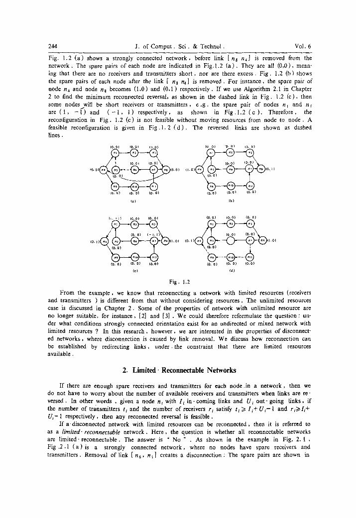
Fig. 1.2 ( a ) shows a strongly connected network, before link [ n8 /14] is removed from the network. The spare pairs of each node are indicated in F ig . l . 2 ( a ) . They are all (0 ,0) , mean- ing that there are no receivers and transmitters shor t , nor are there excess. F ig . 1.2 (b) shows the spare pairs of each node after the link [ n8 n4] is removed. For instance, the spare pair of node n4 and node n8 becomes (1,0) and (0,1) respectively. If we use Algorithm 2.1 in Chapter 2 to find the minimum reconnected reversal, as shown in the dashed link in F ig . 1.2 (c ) , then some nodes will be short receivers or transmitters, e . g . the spare pair of nodes n~ and n7 are ( 1 , - i " ) and ( - 1 , 1) respectively, as shown in F i g . l . 2 ( c ) . Therefore, the reconfiguration in F ig . 1.2 (c) is not feasible without moving resources from node to node. A feasible reconfiguration is given in F ig . I. 2 ( d ) . The reversed links are shown as dashed lines.
tO.O) (0.0) (O.O) (O. O) tO, t)) (0. O)
~o. o) 1o. O) (0. O) 10,0) (0.01 (0.0)
~a) (b)
(t. - l ) (0.0) (0. O) (0,0) (0.0) (0, O)
(0, I) ( I .01 (0,11 1.01
(0. O) (0, O) 10.01 (0. O) 10. O) 10,0)
(c) (d)
Fig. 1.2
From the example, we know that reconnecting a network with limited resources (receivers and transmitters ) is different from that without considering resources. The unlimited resources case is discussed in Chapter 2 . Some of the properties of network with unlimited resource are no longer suitable, for instance, [2] and [3] . We could therefore reformulate the question: un- der what conditions strongly connected orientation exist for an undirected or mixed network with limited resources ? In this research, however, we are interested in the properties of disconnect- ed networks, where disconnection is caused by link removal. We discuss how reconnection can be established by redirecting links, under, the constraint that there are limited resources available.
2. Limited- Reconnectable Networks
If there are enough spare receivers and transmitters for each node. in a network, then we do not have to worry about the number of available receivers and transmitters when links are re- versed. In other words , given a node n~ with [i in- coming links and Ui out- going l inks, if the number of transmitters ti and the number of receivers r i satisfy ti >i [i -F U i - l and ri>~[i + Ui-1 respectively, then any reconnected reversal is feasible.
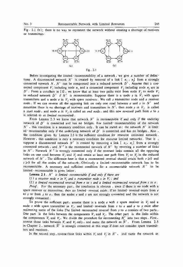
I f a disconnected network with limited resources can be reconnected, then it is referred to as a limited-reconnectable network. Here , the question is whether all reconnectable networks are l imited-reconnectable . The answer is " No " . As shown in the example in Fig. 2. I , Fig .2.1 ( a ) i s a strongly connected network, where no nodes have spare receivers and transmitters. Removal of link [ n6, n t ] creates a disconnection: The spare pairs are shown in
No. 3 Reconnectable Network with Limited Resources 245
Fig. 2.1 (b) ; there is no way to reconnect the network without creating a shortage of receivers or transmitters.
(0. o) (0.0) (0. o1 (0,0)
o o o
10, O) (0.01 (0,01 10. O)
(a) (b)
Fig �9 2.1
Before investigating the limited- reconnectability of a network, we give a number of defini- t ions. A disconnected network N ' is created by removal of a link [ n i , nil from a strongly connected network N. N ' can be compressed into a reduced network D ~ . Assume that a con- nected component Vi including node n i and a connected component Vj including node nj are in D ' . From a corollary in [1] , we know that at least two paths exist from node Vj to node V i in reduced network D ' if N ' is reconnectable. Suppose there is a node s in Vi with spare transmitters and a node e in Vj with spare receivers. We call s transmitter node and e receiver node. If we can reverse all the opposing link on only one road between e and s in N ' and meantime there is no shortage of receivers and transmitters in N ' , then node s in Vi is called a start node , and node e in Vj is called an end node , and this new reversed path from e to s is referred to as l imited reconnected.
From Lemma 2.3 we know that network N ' is reconnectable if and only if the underlay network of D ' is connected and has no bridges. For limited-reconnectability of the network N ' , this condition is a necessary condition only. It can be stated as: the network N ' is limit- ed- reconnectable only if the underlying network of D ' is connected and has no bridges. Also , the condition given by Lemma 2.5 is the sufficient condition for resource unlimited network. However, this condition is only a necessary condition for resource limited networks. That is , suppose a disconnected network N ' is created by removing a link [ n i , n i l from a strongly connected network, and N " is the reconnected network of N ' by reversing a number of links in N ' . Network N '~ is strongly connected only if the reversed links contain all the opposing links on one road between V i and Vj and retain at least one path from V/ to Vj in the reduced network of N ' . The difference here is that a reconnected reversal should retain both r />0 and t 1>0 for all the nodes of the network. Obviously a limited-reconnectable network has to be reconnectable. A necessary and sufficient condition for a reconnectable network N ' to be limited-reconnectable is given below.
Lemma 2.1 . N ' is limited- reconnectable f and only i f there are (1) a receiver node e in Vj and a transmitter node s in Vi ; and (2) a limited reconnected reversal f rom e to s and a limited reconnected reversal f rom s to e . Proof. For the necessary part , the conclusion is obvious , since if there is no node with a
spare receiver or transmitter, then no limited- reversal exists. If no limited- reversal exists from e to s or from s to e , then the nodes e and s are not strongly connected and the network is not strongly connected.
To prove the sufficient part , assume there is a node e with a spare receiver in ~ and a node s with spare transmitter in V i, and limited-reversals from s to e and e to s exist after redirecting some of the links .The limited reconnected reversal from s to e consists of two parts. One part is the links between the components Vi and Vj. The other part is the links within the components Vi and Vj. We divide the procedure for reconnecting N ' into two steps. First , reverse those links between Vi and V/ only, and name the network as ~t, . From Lemma 2.5 in Chapter 2 , network N ' is strongly connected at this stage if does not consider spare transmit- ters and receivers.
In the second step , reverse those links within 1/", and Vj in N ' , and name the network as
246 J. of Comput . Sci. & Technol . Vol. 6
N ". To prove N " is strongly connected, we can show that any reversed link [ n k, nl] within 1I/ and Vj in second step will not disconnect nodes nk and nt themselves. Since nodes s and e are strongly connected by the reversed path from s to e and e to s , nk and nt are strongly con- nected by paths from n t to n k and from nk to nt . The path from nt to nk is a reversed link [ nt, nk] itself. The path from nk to nt consists of three portions segments on the reversed path: (1) path from s to nt, (2) path from nk to e , (3) path from e to s . Therefore, all the nodes within Vi and Vj of N ,/ remain strongly connected. In other words , N " is strongly connected, since ~/ ' was strongly connected. [ ]
Using Lemma 2.1, Theorem 2.1 given below can be proved. The theorem provides an easy way to determine whether a network is l imited-reconnectable. To help state the theorem, we define that : a boundary node of ~ , say bj, is such that bj~ Vj and there are successors of bj in other connected component ; a boundary node of Vi, say hi , is node such that bi6 Vi and there are predecessors of b~ in other connected c0mponent, suppose N ' is reconnectable :
Theorem 2.1. N' is /inn'ted-reconnectable l a n d only if there exist (1) a receiver node e in Vj and at least two paths from e to boundary nodes of Vj; and (2) a transmitter node s in Vi and at least two paths from boundary nodes to s of Vi. Proof. If there exist receiver nodes e and at least two paths from e to boundary nodes
bj in Vj ; and the transmitter node s and at least two paths from boundary nodes b i to S in Vi, then there exist at least two paths from e to s according to Corollary 2.1. One path is shown below, all the spare pairs are shown on top of the nodes:
~1,o) (0 ,0) t n . o ~ (0 ,0 ) (0, 1)
Reconnected network N"can be created by reversing only one path from s to e , as shown by:
It is noticed that there is no receiver and transmitter shorten. And another path from e to s must exist, since there are at least two paths from e to s . According to Lemma 2 .1 , N " is strongly connected.
For necessary part: if there is no receiver node in Vj or no transmitter node in Vi, then there is no way to reconnect the network by reversing link without short of receiver or transmitter.
Furthermore, suppose there is a transmitter node s in V,. , but only one path, say (b~, s) -pa th , exists from boundary node of Vi to e , as shown below ( refer to the path n~ ~ n2--" n3- ' - n 8 in Fig. 2.2 ( a ) ) and N ' is limited reconnectable. Now we are going to show that there must be another node s ' in V i with spare transmitter and at least two paths from bounda- ry nodes of Vi to s '
~o,o) (0 ,0 ) (0 .0 ) (0, i )
Reconnected network c~n be established by first transferring the spare transmitter from s to boundary node bt and reversing all the links on path from Vj to V,.. Transferring a transmitter from s to bl can be done by reversing all the links on the path from bl to s , as shown below. ( refer to the path nl " -n2 ~ n3"-- ns in Fig. 2.2 ( b ) ) :
t o . I ) (o.o) (o, o) ( I . o )
But according to Lemma 2.1, to reconnect N ' a path from boundary of Vj to s is needed. Although there is only one path from boundary node of V/ to s , another boundary node b2 must exist and also at least a road between b2 and s exists. The two cases may exist to create a path from boundary b2 to s , first , the road between boundary node b2 and s is shown
No. 3 Reconnectable Network with Limited Resources 247
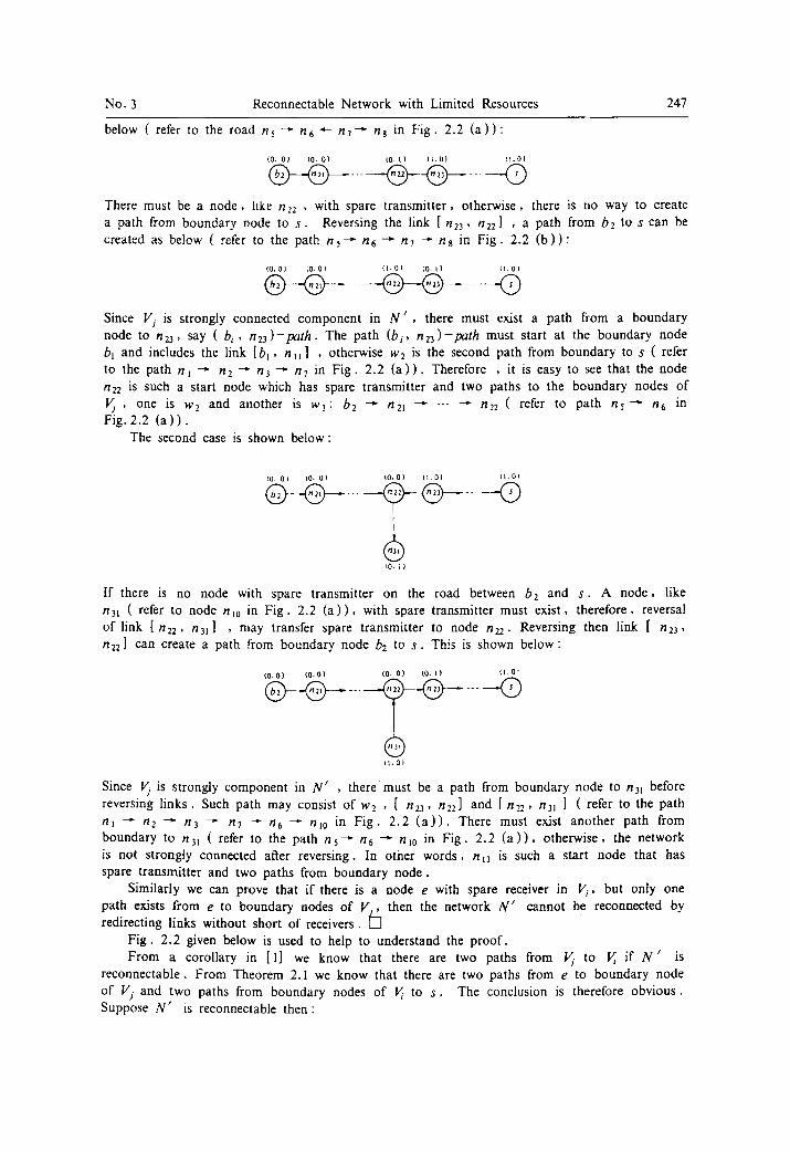
below ( refer to the road n , --" n6 4-- t17 ' '~ n8 in F ig . 2.2 ( a ) ) "
(0. O) (.0. O) (0. t ) ( I .O) ( I .O)
@ - - @ - . . . . @
There must be a node , hke n22 , with spare t ransmit ter , otherwise, there is no way to create a path from boundary node to s . Reversing the link [ n23, n22] , a path from bz to s can be created as below ( refer to the path ns - -" n6 ~ n7 - " n8 in F ig . 2.2 ( b ) ) :
( Q , 0 ) ( 0 , 0 1 { I . O ) ( 0 . 1 1 ( I . 0 l
@__.@ .... . . . . �9
Since Vj is strongly connected component in N ' , there must exist a path from a boundary node to n23, say ( b i , nz3) -pa th . The path (b i, nz3) -path must start at the boundary node bl and includes the link [b l , n t l ] , otherwise w2 is the second path from boundary to s ( refer to the path n t --" n2 ~ n3 --~ n 7 in F ig . 2.2 ( a ) ) . Therefore , it is easy to see that the node n2z is such a start node which has spare transmitter and two paths to the boundary nodes of ~ , one is w2 and another is w3: b~ ~ n21 . . . . . n22 ( refer to path n~- -" n 6 in Fig. 2.2 ( a ) ) .
The second case is shown below:
(0. Ol tO. O) {0.0) f l .O) t l . OI
f I
IO, I I
If there is no node with spare transmitter on the road between b2 and s . A node , like n31 ( refer to node nl0 in F ig . 2.2 ( a ) ) , with spare transmitter must exist , therefore, reversal of link [ n22, n31] , may transfer spare transmitter to node n2z. Reversing then link [ n23, n ~ ) can create a path from boundary node b2 to s . This is shown below:
(0.0) (o.0) (0. O) tO, | ) ~1.0'
~ 1 , 0 )
Since Vs is strongly component in N ' , there must be a path from boundary node to n31 before reversing l inks . Such path may consist of w2 , [ n23, n22] and [ n,.2, n31 ] ( refer to the path nl --" n2 ~ n 3 ~ n7 -'- r/6 ~" nl0 in F ig . 2 .2 ( a ) ) . There must exist another path from boundary to n3~ ( refer to the path ns--" n6 ~ n~0 in F ig . 2.2 ( a ) ) , otherwise, the network is not strongly connected aRer reversing. In other words, n t3 is such a start node that has spare transmitter and two paths from boundary node .
Similarly we can prove that if there is a node e with spare receiver in Vi, but only one path exists from e to boundary nodes of V i , then the network N ' cannot be reconnected by redirecting links without short of receivers.
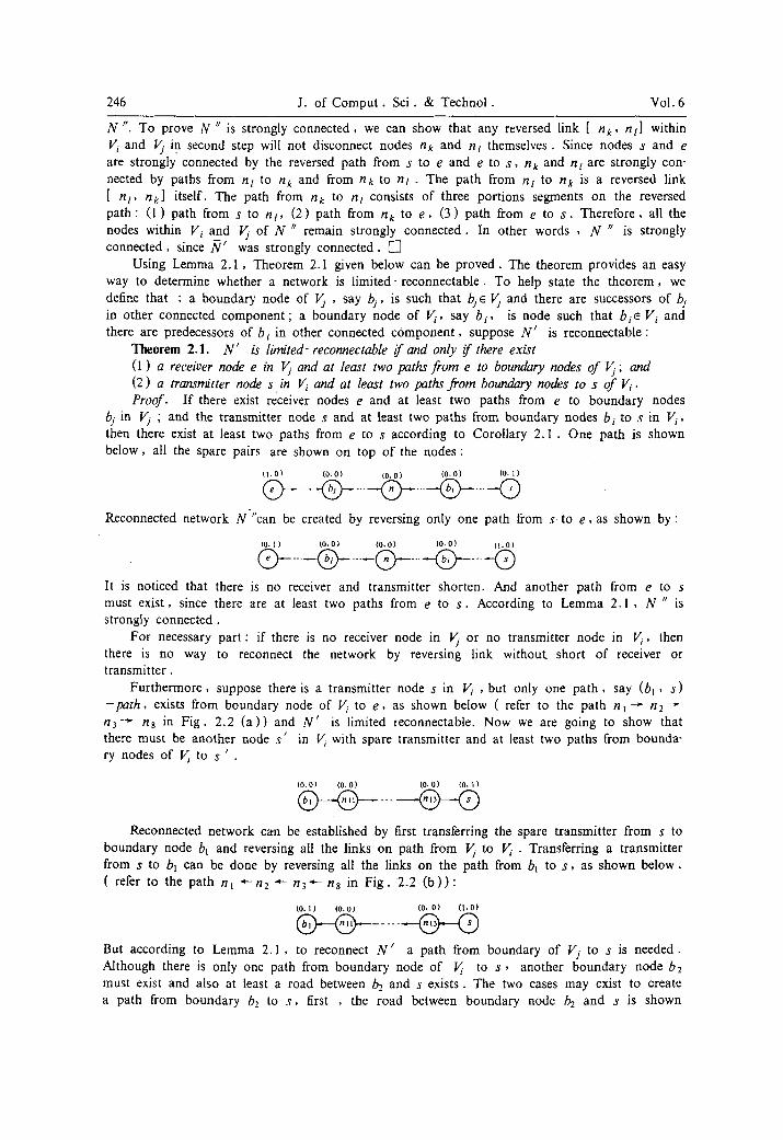
F ig . 2.2 given below is used to help to understand the proof . From a corollary in [1] we know that there are two paths from ~ to V/ if N ' is
reconnectable . From Theorem 2.1 we know that there are two paths from e to boundary node of Vj and two paths from boundary nodes of ~ to s . The conclusion is therefore obvious . Suppose N ' is reconnectable then:

248 J. of C o m p u t . Sci . & Technot . Vol .6
Corollary 2 .1 . N ' is limited-reconnectable i f and only i f there exist (1) a receiver node e in V~ and a transmitter node s in V i , and (2) at least two paths from e to s in N ' �9
(O.O) (0- O) (0 .0) (0.0~ (0- O) (0,0)
(O.O) (0- OI (0.01 (0 .0 ]
( a ) ( b )
(o. O) (0.0) (0. O) {0.0) (0, O) (0.0) - - - ~ - -
l l . O (0.1) (0,11 - . , . . _ . x ~.~.~o. u j ,....~ .,,..,,=.~ ~ ~ �9 0 }
~ 1 1 . 0 1
(0 ,0) (O. IJ ( 0 0 I (t OI
(c) (d)
Fig. 2.2
According to Theorem 2.1 or Corollary 2 .1 , if N ' is l imi ted- reconnec tab le , we can find a boundary node b i in ~ and a boundary node bj in Vj , as shown in Fig. 2 .3 ( a ) . There must exist a path from s to b i in Vi such that the spare transmitter of s can be transferred from e to b~ by reversing all the links on this pa th . Thus , b i becomes a transmitter node of Vi �9 Also there must exist a path from b i to e in V, such that the spare receiver of e can be transferred from e to by by reversing all the links on this pa th . T h u s , b~ becomes a receiver node of V) . From Corollary 2 . 2 . 1 , we know two paths exist from Vjto V i . That is , a path from bj to b, exists between Vj and Vi, as shown in F ig . 2.3 ( a ) .
Since there are at least two paths from Vj to V i if N ' is reconnectabte. Reconnected net- work N " can be created by reversing only one path from s to e , shown 'by F ig . 2.3 ( b ) .
(a)
IO.O) ~0- O~ (0. Ol
(b)
Fig. 2.3 An algorithm provided below can find such reversed road from s to e . Algorithm 2 . 1 .
PROCEDURE shortroad ; VAR Q: ARRAY[ I ..2] of two first-in first-out queues ;
Tree: ARRAY[t ...V] of minimum reversed road tree; BEGIN IV.. : = 0 ; { Assign weight to start node s } enqueuing start node s into Q[0] ; k : = 0 ; / : = 1 ; WHILE (Q[0] AND Q[I] are not empty)DO
BEGIN WHILE (Q[k] is not empty)DO
BEGIN

No. 3 Reconnectable Network with Limited Resources 249
n i : = t a k e a node out from Q[k] ; IF n i=e THEN goto LI ; { This is for finding particular optimal road from e to s only } IF (node ni has unassigned predecessors /~ connected by reversible link) AND (ri>~O) A N D
(ti>~0) THEN BEGIN for all the unassigned predecessors pi of n i connected by reversible link DO
BEGIN enqueuing node pj into Q[ II ; w j : = IVi+ 1 ; { assign weight to node p j } mark the [ink (pj , n i ) as non-reversible link; Tree[ p j l : =r/i ; END ;
delete r/i from queue Q i ; END ;
END ; WHILE (Q[ l ] is not empty ) DO
BEGIN k : = k + l MOD 2; l :=1+1 MOD 2; END;
END ; L1 : Tree gives the reversed road ;
END; { shortroad }
Algorithm 2. l can find the limited reconnected reversal from e to s in linear t ime . H e r e , two f i r s t - in f i r s t -ou t queues , say Q0 and Q~, are needed in the a lgor i thm. The weight of
nodes e , s and n i are denoted by Ws , We and W i , respectively. The weight of a link [n i ,
n.,] is denoted by w,j . pj and s j are predecessor and successor , respectively. F ig . 2.4 shows a l imited-reversed ne twork . F i g . 2.4 (a) is a strongly connected ne twork .
Suppose a transmitter is failure on the node n s �9 A removal of a link [ n s , n~] creates disconnect ion, shown in F ig . 2.4 ( b ) . A strongly connected component which contains transmit-
ter node n4 consists of nodes n 2 , n3 , r/4, n s , t /6, /17. There are two path from boundary
nodes (n2 and ? / 7 ) : /'12 ~ /'13 -~" / / 4 and n7 ~ n3 - - " n 4 �9 Reversal of links [ n 3 , n4] and [ t / 2 ,
n3] can transfer transmitter node from n4 to n2 �9 The other component contains only one node nx. Therefore , nt is both receiver node and boundary node . The n&work can be reconnected by reversing link [ n l , n2] , shown in F ig . 2.4 ( c ) .
tO. tJb (0.0) tO.t) tO.O) {0.0) tO.l) tO.O) IO.O) (l.O)
14).0) 10. O) 11.~1 (0 .0 ) ( 0 ,0 ) [ l . O ) (D.[)) (0, I)) tU l )
l a ) ( h i tc)
Fig. 2.4
References
[1] W. Shi and R. Juels, Connected reorientation of rmxed multigraphs. Network, 19 (1989), 235-246. [2] H . Robbins, A theorem on graphs with an application to a problem of traffic control. American Math .
Monthly, 4G (1939), 281-283. [3] F . Boesch and R. Tindel], Robbin's Theorem for mixed multigraphs. American Math . Monthly, 87
(1980), 716-719.