Embed Size (px)
Citation preview

Reconfiguration Strategies for EnvironmentallyPowered Devices: Theoretical Analysis and
Experimental Validation�
Alex E. Susu1, Michele Magno2, Andrea Acquaviva1,3, David Atienza1,4,and Giovanni De Micheli1,3
1 LSI/EPFL, Lausanne, Switzerland{alex.susu,david.atienza,giovanni.demicheli}@epfl.ch
2 DEIS/University of Bologna, Bologna, [email protected]
3 STI/University of Urbino, [email protected]
4 DACYA/Complutense University, Madrid, [email protected]
Abstract. Environmental energy is becoming a feasible alternative totraditional energy sources for ultra low-power devices such as sensornodes. These devices can run reactive applications that adapt their con-trol flow depending on the sensed data. In order to reduce the energyconsumption of the platform and also to meet the timing constraintsimposed by the application, we propose to dynamically reconfigure thesystem through the use of Field Programmable Gate Array (FPGA) fab-ric such that it executes more efficiently the tasks of the application.
In this paper we present a new approach that enables the designer toefficiently explore different reconfiguration strategies for environmentallypowered systems. For this we define a stochastic model of a harvestingvideo sensor node that captures the behavior of the node and of itsenvironment. We use this approach to investigate the impact of differentreconfiguration strategies for a video surveillance node on metrics ofinterest, such as the expected lifetime or downtime of the system.
Then, we create a hardware implementation of an energy-aware re-configuration manager on top of a custom multi-FPGA board.
Our results show that the systems improve their processing capabili-ties if suitable reconfiguration strategies are defined for their respectiveconfiguration environments.
Keywords: Wireless Sensor Nodes, FPGA, energy harvesting, proba-bilistic model checking, Markov chains.
1 Introduction
The existing and emerging energy harvesting technologies become feasible solu-tions to power up small electronic devices [21,24]. Using harvested energy has� This article builds upon a paper prepared for the third conference on Computing
Frontiers, 2006.
P. Stenstrom (Ed.): Transactions on HiPEAC I, LNCS 4050, pp. 341–360, 2007.c© Springer-Verlag Berlin Heidelberg 2007

342 A.E. Susu et al.
pluses and minuses: the energy from the environment is infinite, thus providingopportunity to increase the autonomy of the system, yet it is unpredictable. Tocope with the unpredictability of the harvested energy we use power adaptationcircuitry and energy storage elements such as rechargeable batteries and super-capacitors, which regulate the supplied power level corresponding to the demand.However, this scheme might not constantly offer the required power because itcan happen that there is not enough energy coming from the environment and,also, not enough energy in the storage elements.
In order to meet timing constraints and, subsequently, in order to reduce theenergy consumption of the platform, we propose to use low power FPGA logicthat can execute more rapidly code that can be parallelized. More exactly, weuse a sensor node which includes a small on-chip FPGA [1] that can implementsignal processing routines together with a low-power microcontroller. Becauseof the limited capacity of the FPGA we can dynamically reconfigure it in orderto load the most energy efficient task sets depending on the sensor context, forexample. However, reconfiguration has a cost in terms of energy and time, sothat a suitable strategy must be designed to determine if and when it is worthto perform system reconfiguration. Clearly, the reconfiguration process itself hasan energy penalty, but our goal is to amortize this cost due to the future savingsoffered by the reconfiguration.
Power management policies can be considered another form of system recon-figuration w.r.t. the application context. The focus of generic power managementpolicies for environmentally powered systems is different from the one of batterypowered devices: while in the latter case we search to maximize the lifetime of thesystem, in the former case a good design objective is to increase the availabilityof the device for long periods of time.
Also, situations might arise where the harvester generates more energy thanrequired by the device after the battery is already full. In this case, the addi-tional energy, which we call energy slack, is wasted. This situation is of practicalrelevance with harvesters such as solar cells, where during long periods withintense external light conditions it becomes difficult to store all the availableenergy.
The work we present brings two contributions. First, we model realistic recon-figurable systems, using PRISM [17], a probabilistic model checking tool. Themodel is used to formally assess the impact of reconfiguration strategies on met-rics of interest such as the lifetime and the availability of the system. We expressquantitatively how various proposed policies improve these metrics.
Second, we describe the implementation of a reconfiguration strategy on aprototype board with FPGA, which uses hardware and software versions of theapplication tasks. The idea behind this policy is to use the otherwise wasted har-vested energy (in case the battery is already full) to reconfigure the system, thusimproving the energy efficiency in the future. In order to match the relativelyhigh power requirements of the prototype board when compared to the powergenerated by practical energy harvesters and, in order to perform experiments

Reconfiguration Strategies for Environmentally Powered Devices 343
in a controllable way, we emulate the harvester with a programmable powergenerator, which generates energy under the form of bursts of constant powerand variable length.
Fig. 1. Generic reconfiguration policy
2 Background Work
Advances in microelectronic technology have been recently exploited to buildlow-cost and low-power miniaturized sensor nodes that can collaborate togetherin sensing and relaying the information, building Wireless Sensor Networks(WSN). Such sensor nodes, integrated with harvesting devices, can exploit theenvironmental energy in order to increase their autonomy [21]. The energy levelprovided by the harvesting devices is determined by the technology in use. Forinstance, solar cells provide between 100mW/cm2 when directed toward brightsun and 100W/cm2 in an illuminated office, while vibrational microgeneratorsprovide 4W/cm3 for human motion [21].
A sensor node consists of the following hardware components [12,8,23]: a mi-croprocessor, data storage, sensors, a data transceiver, and an energy source.The processing performance can be increased with a dedicated Digital SignalProcessing (DSP) unit, an Application-Specific Integrated Circuit (ASIC) or re-configurable hardware (e.g., FPGA) that implements computationally demand-ing or performance constrained tasks.
Currently, most examples of sensor node architectures are microprocessor-based. On the one hand, this provides flexibility for adaptation, since we canimplement multi-modal programs on such nodes, or we can even dynamicallyupload new code on them in order to adapt to a new context.However, a proces-sor executing software is far less efficient in performance, energy consumptionand, even in manufacturing cost than an ASIC. On the other hand, ASICs

344 A.E. Susu et al.
do not have the flexibility for node-level adaptation. Thus, the use of field-programmable hardware, in particular FPGAs, in sensor nodes is a very recentarea of research [18,12]. Reconfigurable logic can provide node flexibility withsignificantly greater energy efficiency than software-only solutions if low-powerFPGA platforms are used in combination with suitable reconfiguration strate-gies. However, because of power and size constraints, suitable FPGAs are limitedin the functionality they can implement. This limitation, coupled with the het-erogeneous application context makes impractical the trivial solution of mappingsimultaneously all the possible tasks on the FPGA. A solution to this problem isto dynamically load in the FPGA the required tasks exactly before being used.
Within the domain of WSN, video sensor nodes hold strong interest for mili-tary, security, robotics, and, recently, also, consumer applications [16,19]. How-ever, due to the high computational requirements and energy costs of videocoders for processors/microcontrollers, mixed hybrid architectures (i.e., micro-processor with DSP/ASIC/FPGA) with efficient partitioning algorithms havebeen suggested as a more suitable option to achieve sufficient performance withlow energy consumption [22].
A similar hybrid approach is taken in the Low power Energy Aware Project(LEAP) [20]. The LEAP platform is a sensor node that can support intensiveprocessing tasks. The LEAP architecture is composed of two modules: a gen-eral purpose computing module used for event-driven computationally intensiveprocessing and a preprocessor module dedicated to low power sensing and energyaccounting. The architecture integrates fine-grained energy dissipation monitor-ing and sophisticated power control scheduling for all subsystems including sen-sor subsystems. The LEAP architecture enables complex energy-aware algorithmdesign by providing a simple interface to control numerous platform and sensorpower modes and report detailed energy usage information.
Lately, several processing power optimization techniques have been proposedfor WSN. In the case of nodes with high duty cycle, one can tune the clockfrequency and the supply voltage of the processing units depending on the work-load [25]. Also, data aggregation strategies between multiple sensor nodes canreduce the redundant information transmitted and the power used in the net-work [6]. In addition, power-aware topology control algorithms have been pro-posed [7]. Another possibility (which is also present in LEAP) is to suspendthe microcontroller, the coprocessors or the radio transceiver according to thecommunication [11] or computation features of the application. The first threemethods are complementary to our reconfigurable approach of sensor nodes;thus, they could be used in combination with the reconfiguration strategies wesuggest in this paper.
3 Analysis of Environmentally Powered ReconfigurableSystems
In this section we focus on the modeling of nodes, with emphasis on the energygenerated by the harvesting device and on the reconfiguration policy. Our goal
Reconfiguration Strategies for Environmentally Powered Devices 345
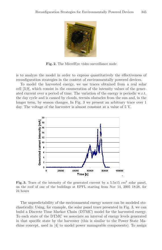
Fig. 2. The MicrelEye video surveillance node
is to analyze the model in order to express quantitatively the effectiveness ofreconfiguration strategies in the context of environmentally powered devices.
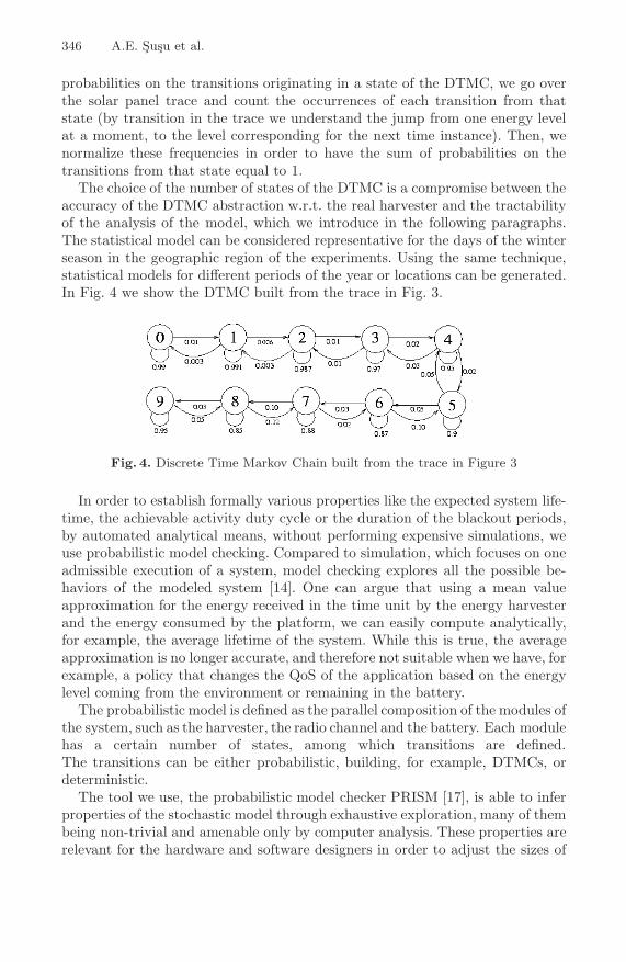
To model the harvested energy, we use traces obtained from a real solarcell [3,9], which consist in the enumeration of the intensity values of the gener-ated current over a period of time. The variation of the energy is periodic w.r.t.the day cycle and is caused by clouds, terrain obstacles from the sun and, in thelonger term, by season changes. In Fig. 3 we present an arbitrary trace over 1day. The voltage of the harvester is almost constant at a value of 5 V.
Fig. 3. Trace of the intensity of the generated current by a 5.5x15 cm2 solar panel,on the roof of one of the buildings at EPFL starting from Nov 14, 2005 18:28, for24 hours
The unpredictability of the environmental energy source can be modeled sto-chastically. Using, for example, the solar panel trace presented in Fig. 3, we canbuild a Discrete Time Markov Chain (DTMC) model for the harvested energy.To each state of the DTMC we associate an interval of energy levels generatedin that specific state by the harvester (this is similar to the Power State Ma-chine concept, used in [4] to model power manageable components). To assign
346 A.E. Susu et al.
probabilities on the transitions originating in a state of the DTMC, we go overthe solar panel trace and count the occurrences of each transition from thatstate (by transition in the trace we understand the jump from one energy levelat a moment, to the level corresponding for the next time instance). Then, wenormalize these frequencies in order to have the sum of probabilities on thetransitions from that state equal to 1.
The choice of the number of states of the DTMC is a compromise between theaccuracy of the DTMC abstraction w.r.t. the real harvester and the tractabilityof the analysis of the model, which we introduce in the following paragraphs.The statistical model can be considered representative for the days of the winterseason in the geographic region of the experiments. Using the same technique,statistical models for different periods of the year or locations can be generated.In Fig. 4 we show the DTMC built from the trace in Fig. 3.
Fig. 4. Discrete Time Markov Chain built from the trace in Figure 3
In order to establish formally various properties like the expected system life-time, the achievable activity duty cycle or the duration of the blackout periods,by automated analytical means, without performing expensive simulations, weuse probabilistic model checking. Compared to simulation, which focuses on oneadmissible execution of a system, model checking explores all the possible be-haviors of the modeled system [14]. One can argue that using a mean valueapproximation for the energy received in the time unit by the energy harvesterand the energy consumed by the platform, we can easily compute analytically,for example, the average lifetime of the system. While this is true, the averageapproximation is no longer accurate, and therefore not suitable when we have, forexample, a policy that changes the QoS of the application based on the energylevel coming from the environment or remaining in the battery.
The probabilistic model is defined as the parallel composition of the modules ofthe system, such as the harvester, the radio channel and the battery. Each modulehas a certain number of states, among which transitions are defined.The transitions can be either probabilistic, building, for example, DTMCs, ordeterministic.
The tool we use, the probabilistic model checker PRISM [17], is able to inferproperties of the stochastic model through exhaustive exploration, many of thembeing non-trivial and amenable only by computer analysis. These properties arerelevant for the hardware and software designers in order to adjust the sizes of

Reconfiguration Strategies for Environmentally Powered Devices 347
the components, such as the harvester and the battery, as well as designing thesoftware layers. For instance, if we employ backward recovery in order to copewith the blackouts [10] we can tune the checkpointing interval s.t. the average lostcomputation is minimized by using the average lifetime of the system determinedwith this method.
In order to instruct PRISM to perform the analysis of a desired property, aquery must be built using the Probabilistic Computational Tree Logic (PCTL)temporal logic [5,13]. For example, we can ask the tool to compute the probabilitythat the system runs out of power for a given battery size and initial levelof environmental energy. In this case, the tool computes the probability thatthe battery module reaches the zero energy state. In the following section, wedevise a model of a realistic reconfigurable system powered by a solar harvesterand a rechargeable battery, the MicrelEye video sensor node used for securityapplications.
Concerning the reconfiguration policy of the system, we present the flowchartof a generic strategy in Fig. 1. The policy stores runtime statistics regardingthe inputs of the application that decide its control flow (e.g., depending ifthe captured image contains a person or not, the system executes different setsof tasks). Based on these statistics, the policy decides which is the best taskcandidate for reconfiguration among the available ones and we load it in theFPGA, if it is not already there. The bitstreams of the task candidates arestored in a special module of the reconfiguration manager, namely, the hardwareblock library, which can be stored in the Flash memory of the available FPGAor in any other storage device directly accessible by the reconfigurable manager.The strategy is also responsible to power manage the components of the system.
The additional energy spent for reconfiguration could prevent the completeexecution of a task that would be otherwise finalized if no reconfiguration isperformed. But, our assumption is that the reconfiguration cost is amortized inthe future by several executions of the more efficient reconfigured task. Moreover,the reconfiguration energy can be provided directly by the harvester at no costwhen the battery is full and the power generated is bigger than the consumption.
To validate the proposed reconfiguration policy, we present in Sect. 4.2 amanager that implements such strategy in a proof-of-concept prototype system.
4 Case Studies and Experimental Measurements
In Sect. 4.1 we illustrate the use of PRISM to explore the possible reconfigurationopportunities of the model introduced in Sect. 3 for various hardware-softwaredesigns of the MicrelEye video sensor node. Then, in Sect. 4.2, we present theimplementation of an energy-aware reconfiguration manager on top of a custommulti-FPGA board and experimental results performed with this platform.
4.1 Evaluation of Reconfiguration Policies Using PRISM
The MicrelEye Node. The MicrelEye (see Fig. 2) is equipped with an Omnivi-sion 7640 video sensor, an ATMEL FPSLIC reconfigurable platform featuring

348 A.E. Susu et al.
an AVR microcontroller and a 40,000 gates FPGA. FPSLIC is one of the lowestpower consuming reconfigurable boards on the market. Its latest version, FP-SLIC II, can put into low-power mode both the microcontroller and the FPGA.
For each captured image, the node performs a set of processing tasks, in orderto determine if a human body is present in the viewer of the camera. In the caseof a positive outcome, the original image is sent to a basestation for furtherprocessing (e.g., face recognition, using a database of features for comparisons).The FPGA is used to perform most of the image processing tasks.
The application running on the platform starts a normal execution cycle bycapturing with the camera an image of 320*240 pixels; we call this the CameraAcquisition (CA) task. We apply on the resulting frame a Background Subtrac-tion (BS) function, which removes the background of the image; this is accom-plished by using an earlier-captured background frame as a reference. At thismoment we can compare the original image (the output of task CA) and theresult of the task BS. If the two images are very different, then it means thatthe original image is mostly background. In this case, we do not perform anymore processing of the image, since the image is considered not to be interesting.If the image resulted from the task BS is not discarded, we continue with theSearch Algorithm (SA) phase, which returns the position within the 320*240frame of a 32*16 window that potentially contains a human body, positionedapproximately 5 meters away from the camera. On this window of 32*16 pixelswe apply the Feature Extraction (FE) function, which performs the average ofthe pixels for each row and column of the window and stores these values ina vector of size 32+16. This vector is handled by the Support Vector Machine(SVM) task that determines if the input vector corresponds to a human bodyor not. At the end of the SVM task, we know with a good degree of confidenceif the captured image contains a human body.
The CA, BS and SA tasks are very computing intensive. To meet deadlines,since a microcontroller does not provide short execution times for the aforemen-tioned tasks, we have to execute these tasks on the FPGA. Therefore, tasks CA,BS, SA and FE are only executed on the FPGA. We execute the SVM task onthe AVR microcontroller, since it can perform fast multiplications, and the SVMtask is multiplication intensive.
The characteristics of the tasks of the detection application are given inTable 1. For the energy consumption values, we assume that we suspend themicrocontroller or the FPGA whenever they are not used.
We model in PRISM the MicrelEye node as the parallel composition of thefollowing modules: i) the harvesting device (SolarHarvester); ii) a rechargeablebattery (Battery); iii) the consumer part of the video node (MicrelEyeNode) that-models the energy intake of the camera, microcontroller and FPGA; iv) the ”view”of the camera (CameraView) that determines if the camera captures a frame onlywith background information or not. To coordinate the simultaneous executionof the modules we define the Clock module. All these modules are synchronizedon the tick action (the term action comes from the terminology used by PRISM)generated by Clock. The structure of the system can be seen in Fig. 5.

Reconfiguration Strategies for Environmentally Powered Devices 349
Table 1. Characterization of the Tasks
Task Execution time [ms] Energy consumed [mJ]CA 40 2.64BS 54.5 12.58BS2 27.25 6.29SA 19.2 4.43FE 0.27 0.0623SVM 89 33.1881FPGA Reconfiguration 22 3.63
Fig. 5. Block diagram of the system
Battery. The rechargeable battery is modeled as a set of states that representthe battery energy levels with deterministic transitions defined by the energyconsumption and generation levels in the current state.
CameraView. We model the view of the camera using two states (the booleanvariable PIFCState specifies what is the current state) and probabilistic transi-tions between them. The transitions represent basically the probability of havinga person (or something that is recognized as a person) in the frame captured bythe camera.
Clock. The clock module does not correspond to a physical component of thesystem. The module has two states that generate the actions tick and tock. Aspreviously explained, Clock is used to trigger the activity of the other compo-nents through the tick action.
MicrelEyeNode. The node is modeled using the MENFPGAState booleanvariable for the two configurations of the FPGA and the MENTaskState variablewith 6 states that keeps track which task is the node currently executing. The

350 A.E. Susu et al.
Fig. 6. The task graph of the software application implemented on the MicrelEye nodefor Policy3
transitions between the states are deterministic and take into account the stateof the CameraView and the level of energy in the battery.
The actual specification of the system is done in the Reactive Modules lan-guage [2], but we do not present it due to space limitation. We define each modulein this language by specifying: i) the variables of the module and their initialvalues and ii) the behavior of each module by a set of commands, where eachdescribes a guard (a predicate that needs to be true to execute the statement)and one deterministic variable update (transition) or more probabilistic updateswith specified probabilities.
The behavior of the model is the following. Initially the battery is full. Inevery time step we add to the battery energy level (variable batteryEnergy) thecontribution from the harvester and subtract the energy consumed by the node,which is computed based on the state of the node (MENTaskState and MENF-PGAState). When the battery is full, the system uses directly the energy fromthe harvester. If this energy is not enough for the given time step, it consumesenergy from the battery as well. If the energy from the harvester is bigger thanwhat the platform requires, then the surplus is wasted. If the system runs out ofenergy (i.e., the system does not have the required energy for executing the cur-rent application cycle) it constantly checks the battery level and restarts onlywhen there is enough energy in the battery to be able to execute the initialapplication cycle.

Reconfiguration Strategies for Environmentally Powered Devices 351
The Strategies. We consider several operation policies, which we comparequantitatively afterwards. The first two of them disallow runtime reconfiguration,while the following two are variations of dynamic reconfiguration policies.
– Policy1 (static, FPGA always active), which assumes that the system is notable to dynamically reconfigure the FPGA, so it has tasks CA, BS, SA andFE statically mapped on the FPGA. Also, we assume that the FPGA cannotbe put into low power mode. On the other hand, the AVR microcontrolleris put into sleep mode when it is not used.
– Policy2 (static, low power FPGA): Once again we assume that the config-uration of the FPGA is assigned at the beginning and cannot be changedduring runtime. We model the use of the FPSLIC II board, and, therefore,the FPGA can be suspended as well, besides the microcontroller.
– Policy3 (dynamic, low power FPGA): This policy takes advantage of thepossibility to dynamically reconfigure the FPGA and to suspend the FPGAand the AVR microcontroller, when no longer used. It means that the mi-crocontroller is turned on only during the execution of the SVM task, whilethe FPGA is suspended only for the tasks CA and SVM.
The dynamic reconfiguration allows the execution of different versionsof a task. For example, since the task BS is the most computing intensive,we can parallelize it by creating two instances of sub-tasks BS that work onhalf of the image each. Thus, this parallelized version of the task BS (whichwe call BS2) has almost half the execution time of the original task BS, butthis comes at the expense of occupying almost double space on the FPGA.This makes task BS2 to have almost half the energy consumption w.r.t. theoriginal task BS, if we consider that the power of the FPGA is the same forthe two different mapping scenarios (tasks CA, BS, SA and FE, versus taskBS2). However, the parallelized version of the task BS occupies a big part ofthe FPGA, and therefore it does not leave space for the SA or the FE tasks.
Having two different FPGA mapping scenarios, we can make use of one orthe other at the right moment by employing dynamic reconfiguration. In thecase we detect that the image is not interesting (immediately after runningthe task BS) we assume that the following images will not be interestingeither with a high probability, and, therefore, we execute task BS2 from nowon, as long as possible. For doing this, we need to dynamically reconfigure theFPGA with the task BS2, if this task is not already mapped on the FPGA,such that for the future frames we benefit of the lower energy consumption.In case we have mapped task BS2 on the FPGA, which occupies the entirereconfigurable logic estate, and we receive a frame that is declared by BS2as being valuable, then we are forced to reconfigure the FPGA in order toload the tasks BS, SA and FE on it. This reconfiguration policy is depictedin Fig. 6, where some of the transitions are annotated with predicates whichdecide if the transition is taken or not.
– Policy4 (dynamic, low power FPGA, harvester used as sensor): This policyenhances Policy3 by sensing the light conditions with the solar panel. If wedetect through the solar panel that there is no light in the environment

352 A.E. Susu et al.
(i.e., the power from the solar panel is almost zero), then we power down thenode. The node restarts when the solar panel captures light and, of course,we have enough energy in the battery to sustain the computations.
We consider Policy2 the baseline non-reconfigurable strategy for ourexperiments.
Fig. 7. Variation of the average lifetime for Policy1, Policy2, Policy3 and Policy4 w.r.t.the capacity of the battery. The node is turned on invariably at 11AM.
Exploration Results of the MicrelEye Node. Before presenting the results,we define precisely the terminology we use. By average lifetime we understand theexpected period of time from the moment we start the system until the momentit runs out of power (note that the system can sleep during its lifetime). By thedowntime of the system over a given period we understand the expected sum ofperiods of time over the given time frame in which the node cannot run becauseit does not have enough energy to proceed with the execution. The downtime ofthe system is the complementary of the uptime for the same period, which canbe easily converted in availability. It is important to mention that the averagedowntime and lifetime are not perfectly complementary: the average downtimeis the sum of periods of blackout for the given period of time, while the lifetimeis just until the first blackout.
For the experiments we run, we assume a probability of 1% of having a per-son in front of the camera. In Fig. 7 we present the expected lifetime of thesystem running each of the defined policies, as a function of the initial (andmaximum) capacity of the battery. Clearly, the lifetime depends on the capacityof the battery in a linear way, since we are outside the energy neutral operationmode (i.e., the power consumption, which is dependent on the duty cycle of theapplication, is higher than the generated power, on average). The initial battery
Reconfiguration Strategies for Environmentally Powered Devices 353
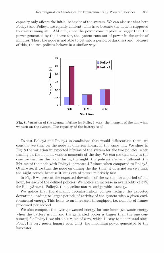
capacity only affects the initial behavior of the system. We can also see that herePolicy3 and Policy4 are equally efficient. This is so because the node is supposedto start running at 11AM and, since the power consumption is bigger than thepower generated by the harvester, the system runs out of power in the order ofminutes. Thus, the node is not able to get into a period of darkness and, becauseof this, the two policies behave in a similar way.
Fig. 8. Variation of the average lifetime for Policy4 w.r.t. the moment of the day whenwe turn on the system. The capacity of the battery is 4J.
To test Policy3 and Policy4 in conditions that would differentiate them, weconsider we turn on the node at different hours, in the same day. We show inFig. 8 the variation in expected lifetime of the system for the two policies, whenturning on the node at various moments of the day. We can see that only in thecase we turn on the node during the night, the policies are very different: thelifetime of the node with Policy4 increases 4.7 times when compared to Policy3.Otherwise, if we turn the node on during the day time, it does not survive untilthe night comes, because it runs out of power relatively fast.
In Fig. 9 we present the expected downtime of the system for a period of onehour, for each of the defined policies. We notice an increase in availability of 37%for Policy3 w.r.t. Policy2, the baseline non-reconfigurable strategy.
We notice that the dynamic reconfiguration policies reduce the expecteddowntime, leading to larger periods of activity of the system with a given envi-ronmental energy. This leads to an increased throughput, i.e. number of framesprocessed per second.
We also compute the average wasted energy for one hour (we waste energywhen the battery is full and the generated power is bigger than the one con-sumed) for Policy1: we obtain a value of zero, which is easy to understand sincePolicy1 is very power hungry even w.r.t. the maximum power generated by theharvester.

354 A.E. Susu et al.
Fig. 9. Variation of the average downtime for a period of one hour for Policy1, Policy2,Policy3, Policy4 w.r.t. the capacity of the battery
We conclude that the reconfiguration strategies, Policy3 and Policy4, canimprove the lifetime of the video node at least with 40% when compared tothe baseline for non-reconfigurable strategies, Policy2, and the availability upto 37%.
4.2 Proof-of-Concept of the Reconfiguration Manager
For validation purposes we build a hardware implementation of an energy-awarereconfiguration manager on top of a custom multi-FPGA board. The consideredplatform is equipped with two FGPAs, where one contains a manager that drivesthe reconfiguration of the other FPGA, which contains the processing logic.
In this set of experiments, we consider a reactive application, which consistsof two different tasks. Both tasks implement, either in software or in the FPGA,slightly different versions of a fourth order Finite Impulse Response filter (FIR),and are named accordingly FIR1 and FIR2. The software version is used when atask needs to be executed and its hardware counterpart is not loaded yet in theFPGA, in the idea of completing the task as soon as possible. The choice of theFIR routine is motivated by the following reasons: (i) it is a signal processingalgorithm suitable for typical sensor networking application; (ii) it results in ahardware implementation easy to fit in a small-sized FPGA suitable for a low-power device; (iii) it is a workload independent routine, which allows controllableexperiments to be performed. In our application, we select for execution one ofthe tasks FIR1 or FIR2 based on the particular value of a sensor reading.
Clearly, this application is simpler than the one presented in Sect. 4.1. Also, animportant difference is the fact that we consider now the environmental energyto come in bursts of different lengths, but of constant power, assumption whichholds better for vibrational or indoors photovoltaic harvesters, for example.

Reconfiguration Strategies for Environmentally Powered Devices 355
In the rest of this section we describe the reconfiguration policy running onthe prototype board, then, the implementation of the board, and, in the end,we discuss the results of the measurements that assess the effectiveness of ourstrategy.
Reconfiguration Policy. The strategy is implemented as code running on theprocessor of the prototype board. This simple policy, depicted in Fig. 10, allowsus to study inherent properties of the reconfiguration strategy in a repeatableand controllable way.
Fig. 10. The event-driven application model
The execution of a task is triggered by the arrival of an energy burst(burst = 1). We create fictive sensor readings by using a pseudo-random gen-erator. Depending on the value of the reading, one of two possible events isgenerated (event = 1, or event = 2). Each event triggers the execution of oneof the two FIR tasks. Along with this, the execution statistics are incrementedfor the corresponding task. The policy has to select between the hardware andsoftware version of the selected task. This is done by checking a shared memorylocation (CHECK PARAM) written by the reconfiguration manager, whichstores which routine is actually loaded in the FPGA. The system continues run-ning as long as there is energy available.
For the given implementation, the number of loops executed during an en-ergy burst of constant length becomes a metric for the energy efficiency of thereconfiguration strategy. Obviously, the lower the amount of energy consumedby each loop, the higher the number of loops that get executed within a singleenergy burst.

356 A.E. Susu et al.
Reconfiguration Manager Implementation and Experimental Results.The custom design board we use to run the reconfiguration policy is equippedwith the URLAP processor [15] (a low power ARM-based processor with 256KB of internal SRAM), 8MB of external DRAM, 512KB of Flash memory andtwo FPGAs. One of the two on-board FPGAs is used for the execution of theFIR tasks, while the other one is used as a reconfiguration manager. The overallsystem architecture is shown in Fig. 11.
Fig. 11. Reconfigurable system architecture
In this design, the FPGAs can be configured to be either memory-mapped orto have a coprocessor interface to the URLAP processor. We use the first alter-native in our experiments to build the interface to the reconfiguration manager.The FPGAs and the URLAP communicate through the shared memory viewand interrupt lines. In this case, the reconfiguration of the FPGA can only bedone at run-time by the URLAP, by using two additional CPLDs.
Since the board is not optimized for being powered by a real harvester, we use aburst emulation system based on the LabVIEW software and a Data AcQuisitionBoard (DAQ). A detailed description of the board and the burst emulationsystem is beyond the scope of this paper. The hardware reconfiguration manageris directly connected to the energy source in order to detect the power of theharvester and the status of the battery, thus being able to detect the energyslack that might be normally wasted. This component that measures the energyand power levels is indicated in Fig. 11 as the Energy Monitor (EM).
Since we do not know in advance the size of the energy burst, we start thereconfiguration process as soon as the power level of the burst is larger than thereconfiguration power. Moreover, we restrict our analysis to the case where wealways have enough energy to perform the reconfiguration process of the FPGA.
The interface of the reconfiguration manager to the main processor is rep-resented by an interrupt signal (INTERRUPT) and a checkpoint signal (CK).

Reconfiguration Strategies for Environmentally Powered Devices 357
The first one gives to the reconfiguration manager the capability of issuing areconfigure command to the main processor in the presence of an energy burst.The second one is used in the statistics collection process. We collect statistics byinserting code checkpoints, which write information about the last task executionin a dedicated shared memory location. The reconfiguration manager reads thenthis information and uses it to update the execution counters of the tasks andother related variables. In order to decide which task to load in the FPGA, weimplement a simple moving average filter, which selects the most frequent taskfrom the 15 previous task executions.
We perform now a set of experiments in which we search to obtain efficiencybounds for the proposed reconfiguration policy. In the following paragraphs weuse the following terminology: i) the burst size indicates the duration of an energyburst; ii) the event distribution is the ratio between the number of consecutiveevents of type 1 and the number of consecutive events of type 2. For instance, anevent distribution of 4:6 means that we have four consecutive events of type 1,followed by six consecutive events of type 2.
Fig. 12. Number of task executions for various unbalanced event distributions
We evaluate the effectiveness of the dynamic reconfiguration policy for differ-ent energy burst sizes. We also measure the energy consumed during the processof reconfiguration process. We find a peak power of 132mW at a frequency of30 MHz of the reprogrammation of the FPGA, with a reconfiguration time ofabout 70ms.
In Fig. 12 we report the number of iterations performed per energy burst,for various unbalanced event distributions. The software only line represents thenumber of iterations obtained when we do not employ any reconfiguration policy,for arbitrary event distributions, since both tasks have identical characteristicsin software. We can see that the proposed policy is more effective for largerenergy bursts, because of the good adaptability of the prediction policy for theactual input event sequence.

358 A.E. Susu et al.
In Fig. 13 we present the energy per iteration consumed as a function of theburst size. This energy takes into account the additional energy spent for thereconfiguration process. The plot is performed using a balanced event distribu-tion, for which a history-based prediction algorithm is more effective. In this plotwe compare our approach with a no reconfiguration case, in which the FPGA isstatically programmed with one of the two routines and is never reconfigured.
We conclude that the system using the proposed reconfiguration strategy con-sumes less energy per iteration than the system using only the software imple-mentation of the tasks, in most of the cases. Since the reconfiguration manageruses a simple prediction policy, with the help of more complex prediction algo-rithms or of policies that exploit more predictable external events, we shouldimprove the effectiveness of the proposed strategies.
Fig. 13. Energy per iteration with balanced event distribution
5 Conclusions
In this paper we have presented modeling and implementation approaches thatuse the reconfigurable hardware existing in the latest and forthcoming sensornode architectures. Our goal is to model the energy coming from the environ-ment and the possibilities of reconfiguration that target to maximize the energyefficiency. We have first performed explorations of stochastic models for environ-mental energy and sensor node architectures and we have shown improvementsin the lifetime and the availability of the system of 40% and 37%, respectively, byemploying several proposed strategies. Then, we have shown an implementationof the proposed reconfiguration manager architecture using a prototype boardwith microcontroller and reconfigurable hardware. Our energy efficiency mea-surements have demonstrated the effectiveness of the employed reconfigurationpolicies.
As future work we plan to extend our modeling methodology to be able toinfer the expected downtime or the energy wasted for more interesting periods oftime (e.g., months, years). Also, we plan to analyze additional real-life workingenvironments (e.g., main doors of buildings, bridges, etc.) and types of harvestingdevices.

Reconfiguration Strategies for Environmentally Powered Devices 359
Acknowledgments
We would like to thank Matthias Fruth, Dave Parker, Rajesh Gupta and An-drey Rybalchenko for the insightful discussions regarding the model checking ofour prototype system. Also, we would like to thank Henri Dubois-Ferriere andGuillermo Barrenetxea for helping us obtain the traces of the solar panel. Thiswork is partially supported by the Swiss NFS Research Grant 20021-109450/1and the Spanish Government Research Grant TIN2005-5619.
References
1. FPSLIC (AVR with FPGA) from Atmel, ATMEL Corporation -www.atmel.com/products/FPSLIC/.
2. Rajeev Alur and Thomas A. Henzinger. Reactive modules. Form. Methods Syst.Des., 15(1):7–48, 1999.
3. Guillermo Barrenetxea, Henri Dubois-Ferriere, Roger Meier, and John Selker. Aweather station for SensorScope. In Demo Session, In Information Processing inSensor Networks (IPSN 2006), 2006.
4. Luca Benini, Alessandro Bogliolo, and Giovanni De Micheli. A survey of designtechniques for system-level dynamic power management. IEEE Transactions onVery Large Scale Integration (VLSI) Systems, 8(3):299–316, June 2000.
5. Andrea Bianco and Luca de Alfaro. Model checking of probabilistic and nondeter-ministic systems. FSTTCS: Foundations of Software Technology and TheoreticalComputer Science, 15, 1995.
6. Benjie Chen, Kyle Jamieson, Hari Balakrishnan, and Robert Morris. Span: anenergy-efficient coordination algorithm for topology maintenance in ad hoc wirelessnetworks. Wirel. Netw., 8(5):481–494, 2002.
7. Xiuzhen Cheng, Bhagirath Narahari, Rahul Simha, Maggie Xiaoyan Cheng, andDan Liu. Strong minimum energy topology in wireless sensor networks: Np-completeness and heuristics. IEEE Transactions on Mobile Computing, 02(3):248–256, 2003.
8. David Culler, Deborah Estrin, and Mani Srivastava. Guest editors’ introduction:Overview of sensor networks. Computer, 37(8):41–49, 2004.
9. Henri Dubois-Ferriere. Sensorscope presentation at NCCR-MICS WG2, 2005.10. E. N. (Mootaz) Elnozahy, Lorenzo Alvisi, Yi-Min Wang, and David B. Johnson. A
survey of rollback-recovery protocols in message-passing systems. ACM Comput.Surv., 34(3):375–408, 2002.
11. Christian C. Enz, Amre El-Hoiydi, Jean-Dominique Decotignie, and Vincent Peiris.Wisenet: An ultralow-power wireless sensor network solution. Computer, 37(8):62–70, 2004.
12. Jessica Feng, Farinaz Koushanfar, and Miodrag Potkonjak. System-architecturesfor sensor networks issues, alternatives, and directions. ICCD, 00:226, 2002.
13. Hans Hansson and Bengt Jonsson. A logic for reasoning about time and probability.Formal Apsects of Computing, 6, 1994.
14. Edmund M. Clarke Jr., Orna Grumberg, and Doron A. Peled. Model checking.MIT Press, Cambridge, MA, USA, 1999.
15. Ties Kluter. URLAP Processor, EPFL LAP Technical Report, 2004.
360 A.E. Susu et al.
16. Greg Kogut, Mike Blackburn, and H.R. Everett. Using video sensor networks tocommand and control unmanned ground vehicles. In AUVSI Unmanned Systemsin International Security (USIS), 2003.
17. Marta Kwiatkowska, Gethin Norman, and David Parker. Prism 2.0: A tool forprobabilistic model checking. QEST, 00:322–323, 2004.
18. John Lach, David Evans, Jon McCune, and Jason Brandon. Power-efficientadaptable wireless sensor networks. In International Conference on Military andAerospace Programmable Logic Devices (MAPLD), 2003.
19. Enrico Magli, Massimo Mancin, and Luca Merello. Low-complexity video com-pression for wireless sensor networks. Proceedings of the International Conferenceon Multimedia and Expo, ICME 2003, 3:585–588, 2003.
20. Dustin McIntire, Kei Ho, Bernie Yip, Amarjeet Singh, Winston Wu, and William J.Kaiser. The low power energy aware processing (leap)embedded networked sensorsystem. In IPSN ’06: Proceedings of the fifth international conference on Infor-mation processing in sensor networks, pages 449–457, New York, NY, USA, 2006.ACM Press.
21. Joseph A. Paradiso and Thad Starner. Energy scavenging for mobile and wirelesselectronics. Pervasive Computing, IEEE, 4(1):18–27, 2005.
22. Jan M. Rabaey, M. Josie Ammer, Julio L. da Silva, Danny Patel, and ShadRoundy. Picoradio supports ad hoc ultra-low power wireless networking. Com-puter, 33(7):42–48, 2000.
23. Kishore Raja, Ioannis Daskalopoulos, Hamadoun Diall, Stephen Hailes, Tom Torfs,Chris Van Hoof, and George Roussos. Sensor Cubes: A modular, ultra-compact,power-aware platform for sensor networks. In International Conference on Infor-mation Processing in Sensor Networks (IPSN SPOTS), April 2006.
24. Shad Roundy, Eli S. Leland, Jessy Baker, Eric Carleton, Elizabeth Reilly, ElaineLai, Brian Otis, Jan M. Rabaey, Paul K. Wright, and V. Sundararajan. Improvingpower output for vibration-based energy scavengers. Pervasive Computing, IEEE,4(1):28–36, 2005.
25. Amit Sinha and Anantha Chandrakasan. Dynamic power management in wirelesssensor networks. IEEE Des. Test, 18(2):62–74, 2001.