Embed Size (px)
Citation preview
arX
iv:2
111.
1511
0v1
[cs
.IT
] 3
0 N
ov 2
021
1
Reconfigurable Intelligent Surface Optimization for
Uplink Sparse Code Multiple AccessIbrahim Al-Nahhal, Member, IEEE, Octavia A. Dobre, Fellow, IEEE, and Ertugrul Basar, Senior Member, IEEE,
Telex M. N. Ngatched, Senior Member, IEEE, and Salama Ikki, Senior Member, IEEE
Abstract—The reconfigurable intelligent surface (RIS)-assistedsparse code multiple access (RIS-SCMA) is an attractive schemefor future wireless networks. In this letter, for the first time,the RIS phase shifts of the uplink RIS-SCMA system areoptimized based on the alternate optimization (AO) techniqueto improve the received signal-to-noise ratio (SNR) for a discreteset of RIS phase shifts. The system model of the uplink RIS-SCMA is formulated to utilize the AO algorithm. For furtherreduction in the computational complexity, a low-complexity AO(LC-AO) algorithm is proposed. The complexity analysis of thetwo proposed algorithms is performed. Monte Carlo simulationsand complexity analysis show that the proposed algorithmssignificantly improve the received SNR compared to the non-optimized RIS-SCMA scenario. The LC-AO provides the samereceived SNR as the AO algorithm, with a significant reductionin complexity. Moreover, the deployment of RISs for the uplinkRIS-SCMA is investigated.
Index Terms—Sparse code multiple access (SCMA), reconfig-urable intelligent surface (RIS), phase shift optimization, discretephase shifts.
I. INTRODUCTION
RECONFIGURABLE intelligent surface (RIS)-
empowered communication has recently become a
promising candidate technology for future wireless networks.
An RIS consists of low-cost passive elements that reflect the
incident signals after adjusting their phases and/or amplitudes
[1], [2]. By intelligent configuration of the incident signals’
phases and/or amplitudes, the constructive and destructive
interference between the reflected signals can be manipulated.
Thus, the transmission environment of the wireless medium
and quality-of-service can be improved without the need for
coding [3].
Sparse code multiple access (SCMA) is a code-domain
non-orthogonal multiple access (NOMA) approach that has
received considerable attention from the research community
in the past few years [4]-[8]. SCMA provides a spectrally
efficient transmission by assigning unique sparse codes to
users who share the wireless medium [9], [10]. The codes’
sparsity property enables the use of the iterative message
passing algorithm (MPA) at the receiver, to provide a near op-
timum decoding performance with an implementable decoding
complexity [11].
This work was supported by the Natural Sciences and Engineering ResearchCouncil of Canada (NSERC), through its Discovery program. The work of E.Basar was supported by TUBITAK under Grant 120E401.
O. A. Dobre, I. Al-Nahhal and T. M. N. Ngatched are with the Facultyof Engineering and Applied Science, Memorial University, St. John’s, NL,Canada, (e-mail: {odobre, ioalnahhal}@mun.ca; [email protected]).
E. Basar is with the CoreLab, Department of Electrical and ElectronicsEngineering, Koç University, Istanbul, Turkey (e-mail: [email protected]).
S. Ikki is with the Department of Electrical Engineering, Lakehead Univer-sity, Thunder Bay, ON, Canada (e-mail: [email protected]).
Power-domain NOMA is another variant of NOMA in
which users’ signals are superposed with different power levels
[12]. Power-domain NOMA assisted by the RIS technology
has been explored in [13]-[17]. In [13] and [14], the downlink
system performance for the RIS-NOMA scheme is improved
for single and multiple antenna systems, respectively. The
authors in [15] and [16] utilize the RIS to maximize the
sum-rate for the downlink millimeter-wave NOMA and uplink
NOMA, respectively. The sum coverage range maximization
is performed in [17] for a downlink RIS-NOMA system. On
the other hand, SCMA and RIS have only been recently
explored in [18], [19]. The first investigation in [18] utilizes
the RIS technology for reducing the decoding complexity of
the conventional uplink SCMA system without optimizing the
RIS phase shifts. In contrast, the authors in [19] provide the
error rate and sum-rate performance analysis for the uplink
RIS-SCMA system. To the best of the authors’ knowledge, no
published work has investigated the optimization of the RIS
phases in detail for RIS-SCMA.
This letter provides two algorithms to optimize the RIS
discrete phase shifts of the uplink RIS-SCMA system, for the
first time. These algorithms are based on alternate optimization
(AO), and are referred to as AO and low-complexity AO (LC-
AO). It is worth noting that employing the AO algorithm
for the uplink RIS-SCMA requires mathematical manipulation
to formulate the system model. The LC-AO algorithm is
proposed to provide the same performance as the AO algo-
rithm, but with a significant reduction in the computational
complexity. The proposed algorithms considerably improve
the received signal-to-noise ratio (SNR) compared to the
non-optimized (i.e., blind) scenario by iteratively optimizing
the discrete RIS phase shifts. Monte Carlo simulations and
complexity analysis are provided to assess the proposed algo-
rithms.
The remainder of this letter is organized as follows: Section
II presents the system model of the uplink RIS-SCMA system.
The formulation of the optimization problem and the proposed
algorithms are introduced in Section III, while their complexity
is analyzed in Section IV. Finally, simulation results and
conclusions are presented in Sections V and VI, respectively.
II. UPLINK RIS-SCMA SYSTEM MODEL
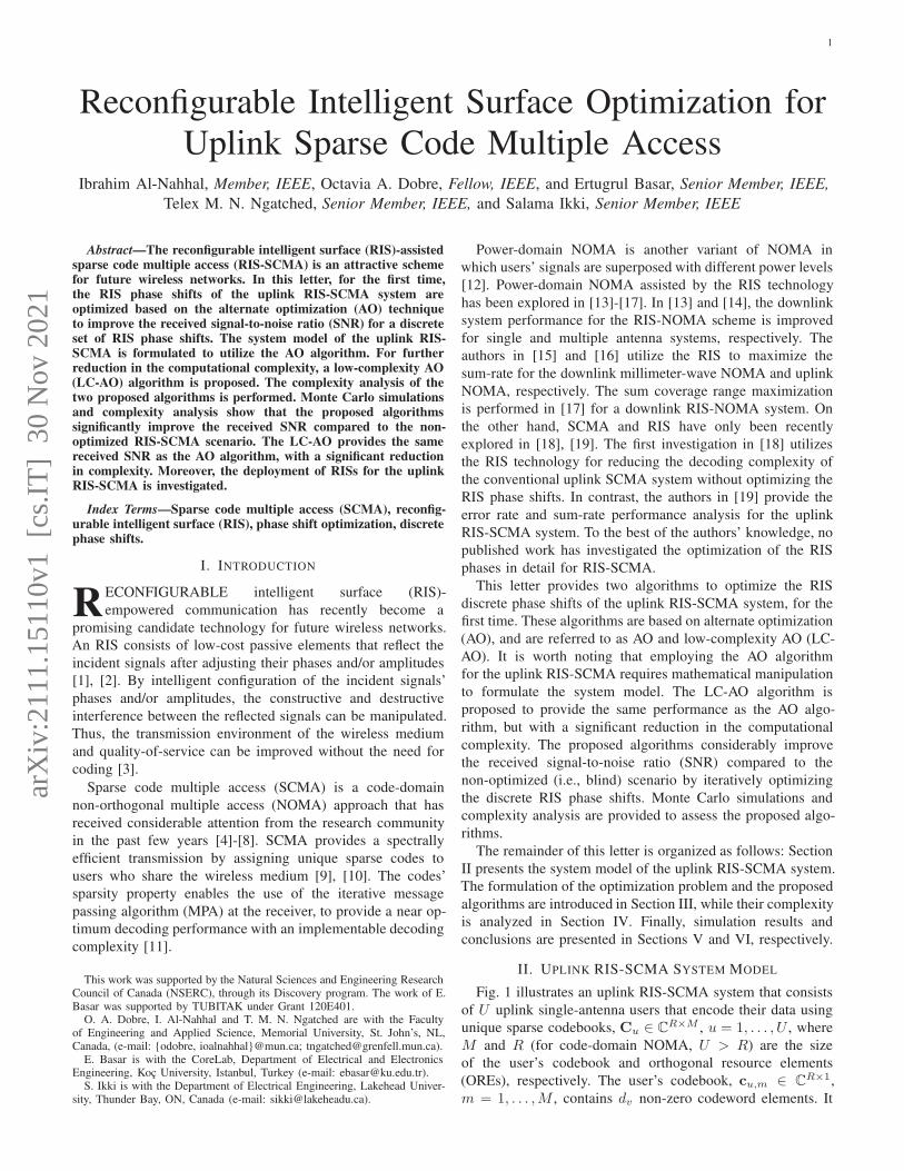
Fig. 1 illustrates an uplink RIS-SCMA system that consists
of U uplink single-antenna users that encode their data using
unique sparse codebooks, Cu ∈ CR×M , u = 1, . . . , U , where
M and R (for code-domain NOMA, U > R) are the size
of the user’s codebook and orthogonal resource elements
(OREs), respectively. The user’s codebook, cu,m ∈ CR×1,
m = 1, . . . ,M , contains dv non-zero codeword elements. It
2
u U1
SCMA Encoder
1 2 1 2 5 63 4
1 42 3
VNs
FNs
1 M
DSP unit
. . .. . .
RISr
ng
r
nug ,
RIS Controller
r
uh
n-th RIS Element
UU11
SCMA Encoder
11 22 55 66311111111111111111111111111131111111111111111111111111 42222222222222222222222222242222222222222222222222222
11 422 333
VNs
FNsFNs
1
Rr
n
DSP unitD
r
nu ,
RRIS
RIS Controller
r
u
nn- hthhh RIS ElementR
Fig. 1: Uplink RIS-SCMA system.
is worth noting that the sparse codebooks for all users are
designed to share the same R OREs in which the number of
non-zero shared codeword elements for each ORE, df , is fixed.
It is assumed that each single-antenna user delivers its data to a
single-antenna base station (BS) through a line-of-sight (LoS)
path and through an N passive reflecting RIS elements.
The ORE for SCMA can be a frequency-unit or a time-unit
depending on the nature of the problem. In this paper, a time-
unit ORE is considered for the RIS-SCMA systems. For each
ORE, the received signal, yr, at the receiver-side is given by
yr =∑
u∈Λr
(N∑
n=1
(gru,ne
−φn grn + hru)
)
cru,m + wr , (1)
where hru, grn and gru,n are the channel coefficients of the u-
th user to BS (i.e., the LoS component), n-th RIS element
to BS, and u-th user to n-th RIS element, respectively, at
the r-th ORE. cru,m is the u-th user’s codeword at the r-thORE. The additive white Gaussian noise at the r-th ORE is
denoted as wr ∼ N (0, σ2r ) with zero-mean and variance of
σ2r ; for simplicity, it is assumed that the noise variance for all
R OREs is the same. Λr denotes the users’ indices that are
interfering over the r-th ORE. Here, φn represents the n-th
discrete phase shift of the RIS reflecting at the r-th ORE, and
its value is taken from a finite set, L ∈ [−π, π), as
φn ∈ L ={−π, −π +∆, . . . , −π + (2b − 1)∆
}∀n, (2)
where b represents the number of quantization bits for each
RIS phase shift, and ∆ = 2π/2b is the step size between
two successive discrete values of the RIS phase shifts. At the
receiver, the MPA [18] is employed to decode the users’ mes-
sages by iteratively updating the messages between function
nodes (FN) and variable nodes (VN), as illustrated in Fig. 1.
The received SNR at the r-th ORE, Γr, is
Γr =E
σ2r
∣∣∣∣∣
∑
u∈Λr
(N∑
n=1
(gru,ne
−φn grn + hru)
)∣∣∣∣∣
2
, (3)
where E is the average transmitted user energy. Here, the
optimization of the RIS phase shifts aims to maximize the
received SNR at the r-th ORE, as
(P1): maxφn
∣∣∣∣∣
∑
u∈Λr
(N∑
n=1
(gru,ne
−φn grn + hru)
)∣∣∣∣∣
2
(4)
s.t. φn ∈ L, ∀n, ∀r. (5)
The optimization problem in (P1) is non-convex due to the
objective function itself and the finite values of the phase
shifts. There is no unique method to relax a non-convex
problem to obtain an optimal solution efficiently. The optimal
solution can be achieved by utilizing an exhaustive search for
all combinations of the discrete RIS phase shifts. However,
the computational complexity of this approach is practically
prohibitive. It is worth noting that optimizing the received
SNR can be considered for the RIS-SCMA system due to the
shaping gain of the users’ sparse codebooks.
III. PROPOSED RIS PHASE SHIFTS OPTIMIZATION
As mentioned before, finding the optimal set of RIS phase
shifts requires trying ∼ (2bNR) possible combinations, which
is extremely costly and infeasible even for a small-scale prob-
lem. A sub-optimal solution with acceptable computational
complexity can be obtained by utilizing the AO concept. It
should be emphasized that the AO algorithm is adopted in
[20] for a different wireless communication scheme, here, a
reformulation of (P1) is needed to apply the AO algorithm.
A. Proposed AO Algorithm
In the proposed AO algorithm, the solution of (P1)
in (4) can be obtained by iteratively optimizing the
RIS phase shifts one at a time at each ORE. Consider
grn ∈ C1×N = [gr1 . . . g
rn . . . g
rN ], Φr ∈ CN×N =
diag([e−φ1 . . . e−φn . . . e−φN ]) with diag(·) reshaping the
corresponding vector to a diagonal square matrix, Gr ∈CN×df = [gr
1 . . .gru . . . g
rdf] with gr
u ∈ CN×1 =
[gru,1 . . . gru,n . . . g
ru,N ]† ∀u ∈ Λr, hr ∈ C1×df =
[hr1 . . . hru . . . h
rdf] ∀u ∈ Λr, and cr ∈ Cdf×1 =
[cr1,m . . . cru,m . . . crdf ,m]† ∀u ∈ Λr, with † denoting transpose.
Therefore, yr in (1) and Γr in (3) can respectively be written
as
yr = (grnΦ
rGr + hr) cr + wr , (6)
and
Γr =E
σ2r
‖grnΦ
rGr + hr‖2 . (7)
The proposed AO algorithm employs an exhaustive search
for only one phase shift, while the remainingN−1 phase shifts
are kept fixed. An iterative procedure is required to improve
the performance of the proposed AO algorithm. The optimized
phase shift of the n-th RIS element for the r-th ORE, φ∗n, is
φ∗n = arg max
φn,t ∈ L‖gr
nΦr(φn,t)G
r + hr‖2 , r = 1, . . . , R,
(8)
where Φr(φn,t) = diag([e−jφ1,t−1 . . . e−jφn,t . . . e−jφN,t−1 ])is the phase shifts matrix with only varying φn,t at the t-th iteration, while the rest of phase shifts are given by the
previous iteration (i.e., the (t − 1)-th iteration). Finally, the
algorithm stops after T iterations. Algorithm 1 summarizes
the steps of the proposed AO algorithm.
3
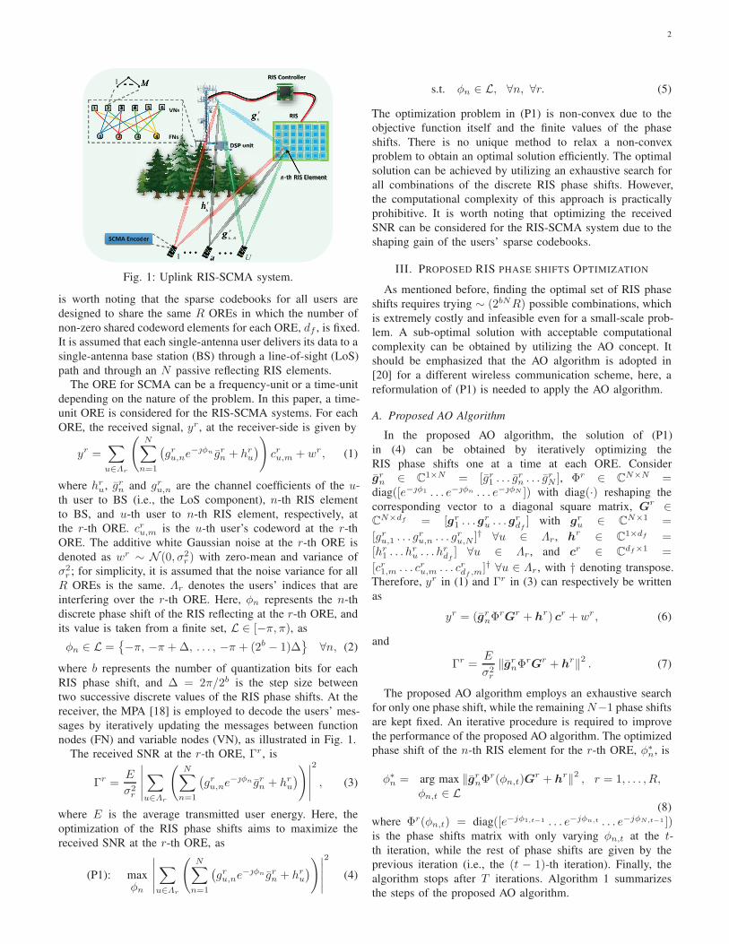
Algorithm 1 The proposed AO algorithm pseudo-code.
• Input: grn, Gr, hr, L, and maximum # of iteration, T ;
• Initiate: φn,0 = 0 for n = 1, . . . , N ;
1: Set: t← 1;
2: for r = 1 to R3: while t ≤ T , do
4: for n = 1 to N5: Buffer: ζmax = [·];6: for l = 1 to 2b
7: ζmax(1, l)← ‖grnΦ
r(φn,t,l)Gr + hr‖2;
8: end for
9: Find: imax = arg max{ζmax};10: Update: φn,t ← L(imax);11: end for
12: Set: t← t+ 1;
13: end while
14: Set: Φr ← diag([e−jφ1,T . . . e−jφN,T ])15: end for
• Output Φr for r = 1, . . . , R.
B. Proposed LC-AO Algorithm
As seen from line #7 in Algorithm 1, the AO algorithm
calculates some terms that are not a function of φn,t, in
each iteration. Thus, we can achieve the same performance
as Algorithm 1 with a significant reduction in computational
complexity by eliminating these terms. In this subsection, the
target is to find and neglect these unnecessary terms.
To achieve this goal, consider grnΦ
rGr = vrdiag(grn)G
r,
where vr ∈ C1×N = [e−jφ1 . . . e−jφN ], and Ξ
r ∈ CN×df =
diag(grn)G
r. Thus, (7) can be written as
Γr =E
σ2r
‖vrΞ
r + hr‖2
=E
σ2r
vrDr(vr)H︸ ︷︷ ︸
Term 1
+ 2ℜ{vrd
r}
︸ ︷︷ ︸
Term 2
+ ‖hr‖2
, (9)
where ℜ{·} returns the real value of a complex number, Dr ∈CN×N = Ξ
r(Ξr)H , and dr∈ CN×1 = Ξ
r(hr)H . Thus, the
(k, n)-th element of Dr (i.e., drk,n) and the k-th element of
dr
(i.e., drk) are respectively given as
drk,n =
df∑
i=1
(grk,ig
rk
) (grn,ig
rn
)∗, (10)
and
drk =
df∑
i=1
(grk,ig
rk
)(hri )
∗, (11)
where (·)∗ denotes the conjugate of the complex number.
Now, we need to find the terms in (9) that are not a function
of φn, to be neglected. Term 1 in (9) can be written as
vrDr(vr)H = Ar1 (φn) +Ar
1 (Φr\φn) , (12)
where
Ar1 (φn) = 2ℜ
e−jφn
N∑
k 6=n
ejφk(drk,n
)∗
, (13)
and
Ar1 (Φ
r\φn) =N∑
n=1
drn,n + 2ℜ
N∑
i6=n
N∑
j 6=n
ej(φi−φj)(dri,j)∗
.
(14)
Similarly, Term 2 in (9) can be written as
2ℜ{vrd
r}= Ar
2 (φn) +Ar2 (Φ
r\φn) , (15)
where
Ar2 (φn) = 2ℜ
{e−jφn drn
}, (16)
and
Ar2 (Φ
r\φn) = 2ℜ
N∑
i6=n
e−jφi dri
. (17)
Hence, Ar1 (Φ
r\φn) in (14), Ar2 (Φ
r\φn) in (17) and ‖hr‖2
in (9) can be neglected in solving (8) since they are indepen-
dent of φn. Consequently, using (13) and (16), the solution of
(8) yields
φ∗n = arg max
φn,t ∈ Lℜ
e−jφn,t(drn +
N∑
k 6=n
ejφk,t−1(drk,n)∗)
︸ ︷︷ ︸
Term 3
, (18)
where drk,n and drn are given by (10) and (11), respectively.
Iterations are also required to improve the performance of (18).
It is worth noting that the LC-AO algorithm calculates Term
3 in (18) only once for all 2b possible combinations of φn.
Algorithm 2 summarizes the proposed LC-AO algorithm.
IV. COMPLEXITY ANALYSIS
The computational complexity of the proposed AO and LC-
AO algorithms is derived in terms of the real additions and real
multiplications. For the AO algorithm, the matrix and vector
operation inside the norm in (8) requires 2N(2df + 1) and
4N(df + 1) real additions and multiplications, respectively,
for each possible value of φn. Furthermore, the second norm
performs (2df −1) and 2df real additions and multiplications,
respectively. Thus, the total number of real additions, RAAO,
and multiplications, RMAO, required to perform the AO algo-
rithm is respectively given as
RAAO = RN2b (2N (2df + 1) + 2df − 1) , (19)
RMAO = RN2b (4N (df + 1) + 2df ) . (20)
In the proposed LC-AO algorithm, (10) and (11) require
(8df−2) and (6df−2) real additions, as well as 12df and 8dfreal multiplications, respectively. Thus, Term 3 in (18) requires
N(8df + 1) − 2(df + 1) and 4N(3df + 1) − 4(df + 1) real
additions and multiplications, respectively. It is worth noting
that the LC-AO algorithm calculates Term 3 only once for
all 2b possibilities of φn. Therefore, the total number of real
additions, RALC-AO, and multiplications, RMLC-AO, required to
perform the LC-AO algorithm are respectively given as
RALC-AO = RN(2b+1 +N (8df + 1)− 2 (df + 1)
), (21)
RMLC-AO = RN(2b+2 + 4N (3df + 1)− 4 (df + 1)
). (22)
4
Algorithm 2 The proposed LC-AO algorithm pseudo-code.
• Input: grn, Gr, hr, L, and maximum # of iteration, T ;
• Initiate: φn,0 = 0 for n = 1, . . . , N ;
1: Set: t← 1;
2: for r = 1 to R3: while t ≤ T , do
4: for n = 1 to N5: Buffer: ζmax = [·], and ψr
n = [·];6: for k = 1 to N7: if k 6= n, do
8: drk,n =∑df
i=1
(
grk,igrk
) (grn,ig
rn
)∗;
9: Set: ψrn ← ψr
n + ejφk,t−1(drk,n)∗;
10: end if
11: end for
12: Compute: drn =∑df
i=1
(grn,ig
rn
)(hri )
∗;
13: Compute: Term 3 = drn + ψrn;
14: for l = 1 to 2b
15: ζmax(1, l)← ℜ{e−jφn,t,l × Term 3
};
16: end for
17: Find: imax = arg max{ζmax};18: Update: φn,t ← L(imax);19: end for
20: Set: t← t+ 1;
21: end while
22: Set: Φr ← diag([e−jφ1,T . . . e−jφN,T ])23: end for
• Output Φr for r = 1, . . . , R.
V. SIMULATION RESULTS
In this section, Monte Carlo simulations are used to evaluate
the proposed AO and LC-AO algorithms for uplink RIS-
SCMA. The codebooks for all users are set based on the
approach in [10]. The parameters employed in simulations are
U = 6, R = 4, df = 3, b = 3, T = 3, and M = 2. As
depicted in Fig. 2, the simulation setup is as follows: d = 40 m,
dp = 1.5 m, d1 =√
d2p + d2o m, and d2 =√
d2p + (d− do)2
m. The overall system path loss is (λ4d−21 d−2
2 )/(256π2) [21],
where λ denotes the signal wavelength for the 2.4 GHz
operating frequency. All channels are Rician fading with a
factor of 1. The average received SNR of the RIS-SCMA
system for all R OREs, Γ, in dB is used to assess the behavior
of the proposed optimization algorithms. The blind scenario
mentioned in the simulation results refers to the case where
the RIS reflects the incident signals without performing any
optimization on the phase shifts (i.e., φn = 0, ∀n and ∀r).This scenario is included only to show the gain obtained from
comparing the optimized scenario with the non-optimized one.
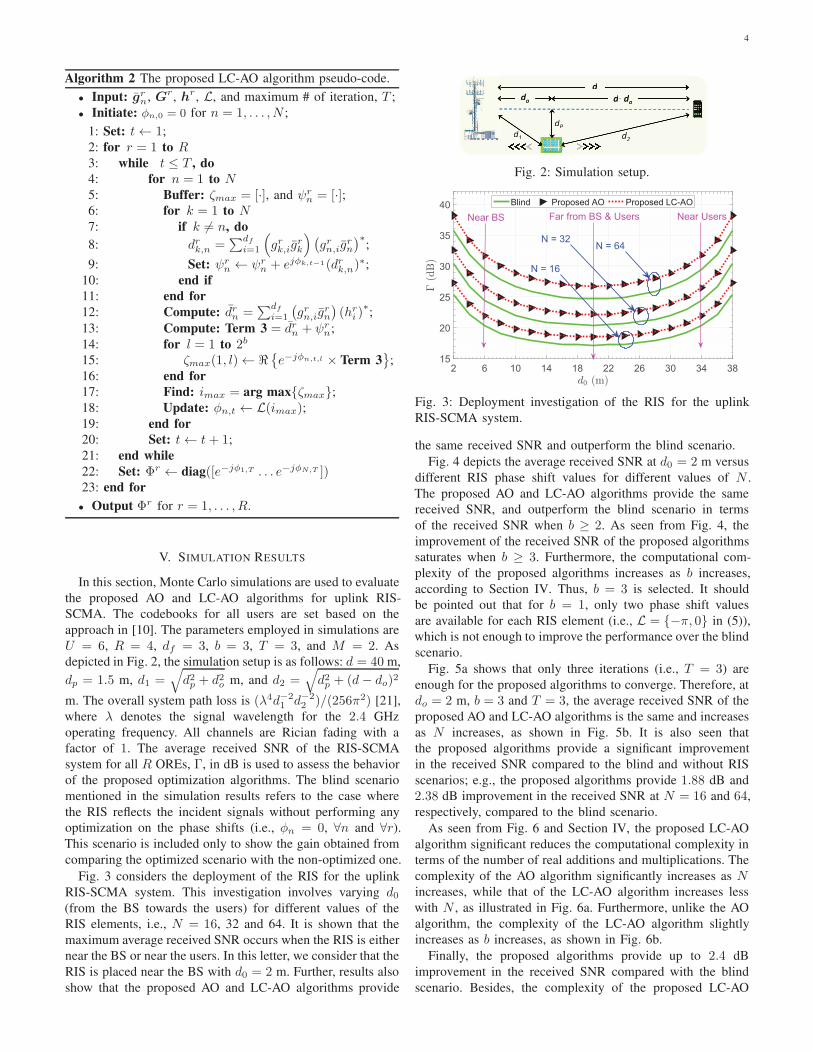
Fig. 3 considers the deployment of the RIS for the uplink
RIS-SCMA system. This investigation involves varying d0(from the BS towards the users) for different values of the
RIS elements, i.e., N = 16, 32 and 64. It is shown that the
maximum average received SNR occurs when the RIS is either
near the BS or near the users. In this letter, we consider that the
RIS is placed near the BS with d0 = 2 m. Further, results also
show that the proposed AO and LC-AO algorithms provide
d
dP
d2
d1
do d- d
o
d
dP
d2
dd1
do
d d- do
d
Fig. 2: Simulation setup.
2 6 10 14 18 22 26 30 34 3815
20
25
30
35
40 Blind Proposed AO Proposed LC-AO
N = 16
N = 32N = 64
Far from BS & Users Near UsersNear BS
Fig. 3: Deployment investigation of the RIS for the uplink
RIS-SCMA system.
the same received SNR and outperform the blind scenario.
Fig. 4 depicts the average received SNR at d0 = 2 m versus
different RIS phase shift values for different values of N .
The proposed AO and LC-AO algorithms provide the same
received SNR, and outperform the blind scenario in terms
of the received SNR when b ≥ 2. As seen from Fig. 4, the
improvement of the received SNR of the proposed algorithms
saturates when b ≥ 3. Furthermore, the computational com-
plexity of the proposed algorithms increases as b increases,
according to Section IV. Thus, b = 3 is selected. It should
be pointed out that for b = 1, only two phase shift values
are available for each RIS element (i.e., L = {−π, 0} in (5)),
which is not enough to improve the performance over the blind
scenario.
Fig. 5a shows that only three iterations (i.e., T = 3) are
enough for the proposed algorithms to converge. Therefore, at
do = 2 m, b = 3 and T = 3, the average received SNR of the
proposed AO and LC-AO algorithms is the same and increases
as N increases, as shown in Fig. 5b. It is also seen that
the proposed algorithms provide a significant improvement
in the received SNR compared to the blind and without RIS
scenarios; e.g., the proposed algorithms provide 1.88 dB and
2.38 dB improvement in the received SNR at N = 16 and 64,
respectively, compared to the blind scenario.
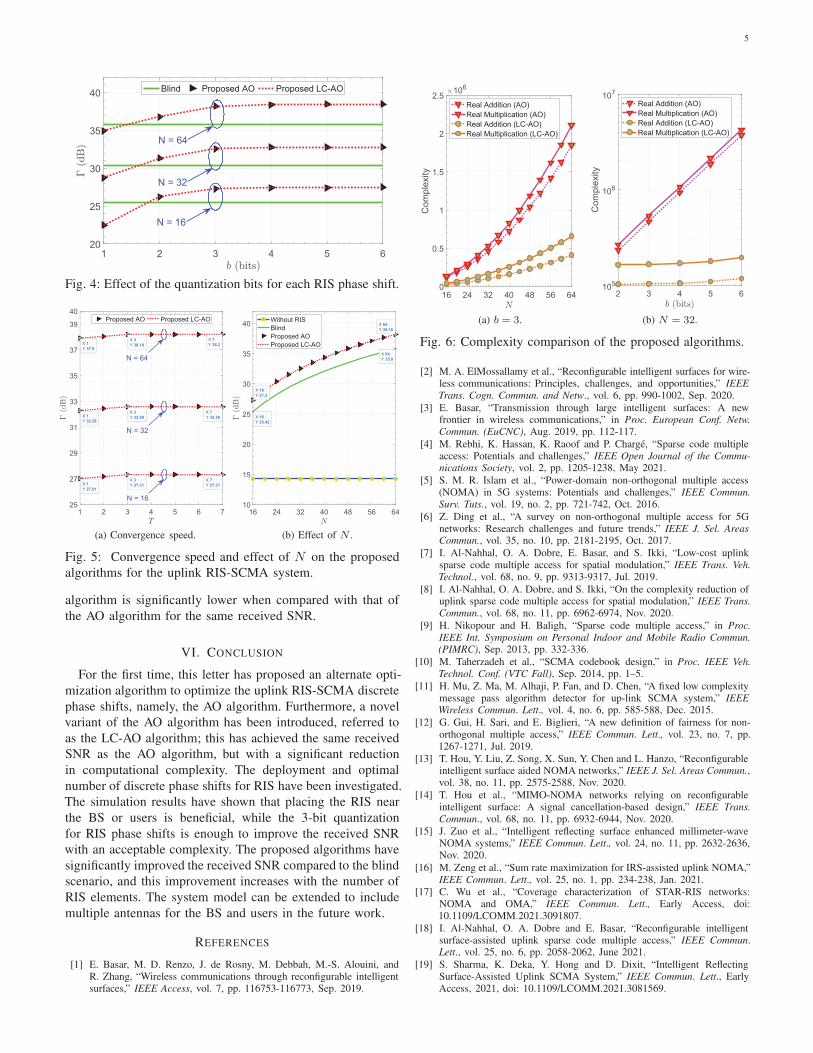
As seen from Fig. 6 and Section IV, the proposed LC-AO
algorithm significant reduces the computational complexity in
terms of the number of real additions and multiplications. The
complexity of the AO algorithm significantly increases as Nincreases, while that of the LC-AO algorithm increases less
with N , as illustrated in Fig. 6a. Furthermore, unlike the AO
algorithm, the complexity of the LC-AO algorithm slightly
increases as b increases, as shown in Fig. 6b.
Finally, the proposed algorithms provide up to 2.4 dB
improvement in the received SNR compared with the blind
scenario. Besides, the complexity of the proposed LC-AO
5
1 2 3 4 5 620
25
30
35
40Blind Proposed AO Proposed LC-AO
N = 32
N = 16
N = 64
Fig. 4: Effect of the quantization bits for each RIS phase shift.
1 2 3 4 5 6 725
27
29
31
33
35
37
39
40Proposed AO Proposed LC-AO
N = 64
N = 32
N = 16
X 3
Y 38.19X 1
Y 37.9
X 1
Y 32.28
X 3
Y 32.58
X 3
Y 27.31X 1
Y 27.01
X 7
Y 38.2
X 7
Y 32.58
X 7
Y 27.31
(a) Convergence speed.
16 24 32 40 48 56 6410
15
20
25
30
35
40Without RIS
Blind
Proposed AO
Proposed LC-AO
X 16
Y 25.42
X 16
Y 27.3
X 64
Y 38.18
X 64
Y 35.8
(b) Effect of N .
Fig. 5: Convergence speed and effect of N on the proposed
algorithms for the uplink RIS-SCMA system.
algorithm is significantly lower when compared with that of
the AO algorithm for the same received SNR.
VI. CONCLUSION
For the first time, this letter has proposed an alternate opti-
mization algorithm to optimize the uplink RIS-SCMA discrete
phase shifts, namely, the AO algorithm. Furthermore, a novel
variant of the AO algorithm has been introduced, referred to
as the LC-AO algorithm; this has achieved the same received
SNR as the AO algorithm, but with a significant reduction
in computational complexity. The deployment and optimal
number of discrete phase shifts for RIS have been investigated.
The simulation results have shown that placing the RIS near
the BS or users is beneficial, while the 3-bit quantization
for RIS phase shifts is enough to improve the received SNR
with an acceptable complexity. The proposed algorithms have
significantly improved the received SNR compared to the blind
scenario, and this improvement increases with the number of
RIS elements. The system model can be extended to include
multiple antennas for the BS and users in the future work.
REFERENCES
[1] E. Basar, M. D. Renzo, J. de Rosny, M. Debbah, M.-S. Alouini, andR. Zhang, “Wireless communications through reconfigurable intelligentsurfaces,” IEEE Access, vol. 7, pp. 116753-116773, Sep. 2019.
16 24 32 40 48 56 640
0.5
1
1.5
2
2.5
Co
mp
lexity
106
Real Addition (AO)
Real Multiplication (AO)
Real Addition (LC-AO)
Real Multiplication (LC-AO)
(a) b = 3.
2 3 4 5 6105
106
107
Co
mp
lexity
Real Addition (AO)
Real Multiplication (AO)
Real Addition (LC-AO)
Real Multiplication (LC-AO)
(b) N = 32.
Fig. 6: Complexity comparison of the proposed algorithms.
[2] M. A. ElMossallamy et al., “Reconfigurable intelligent surfaces for wire-less communications: Principles, challenges, and opportunities,” IEEE
Trans. Cogn. Commun. and Netw., vol. 6, pp. 990-1002, Sep. 2020.
[3] E. Basar, “Transmission through large intelligent surfaces: A newfrontier in wireless communications,” in Proc. European Conf. Netw.
Commun. (EuCNC), Aug. 2019, pp. 112-117.
[4] M. Rebhi, K. Hassan, K. Raoof and P. Chargé, “Sparse code multipleaccess: Potentials and challenges,” IEEE Open Journal of the Commu-
nications Society, vol. 2, pp. 1205-1238, May 2021.
[5] S. M. R. Islam et al., “Power-domain non-orthogonal multiple access(NOMA) in 5G systems: Potentials and challenges,” IEEE Commun.
Surv. Tuts., vol. 19, no. 2, pp. 721-742, Oct. 2016.
[6] Z. Ding et al., “A survey on non-orthogonal multiple access for 5Gnetworks: Research challenges and future trends,” IEEE J. Sel. Areas
Commun., vol. 35, no. 10, pp. 2181-2195, Oct. 2017.
[7] I. Al-Nahhal, O. A. Dobre, E. Basar, and S. Ikki, “Low-cost uplinksparse code multiple access for spatial modulation,” IEEE Trans. Veh.
Technol., vol. 68, no. 9, pp. 9313-9317, Jul. 2019.
[8] I. Al-Nahhal, O. A. Dobre, and S. Ikki, “On the complexity reduction ofuplink sparse code multiple access for spatial modulation,” IEEE Trans.
Commun., vol. 68, no. 11, pp. 6962-6974, Nov. 2020.
[9] H. Nikopour and H. Baligh, “Sparse code multiple access,” in Proc.
IEEE Int. Symposium on Personal Indoor and Mobile Radio Commun.
(PIMRC), Sep. 2013, pp. 332-336.
[10] M. Taherzadeh et al., “SCMA codebook design,” in Proc. IEEE Veh.
Technol. Conf. (VTC Fall), Sep. 2014, pp. 1–5.
[11] H. Mu, Z. Ma, M. Alhaji, P. Fan, and D. Chen, “A fixed low complexitymessage pass algorithm detector for up-link SCMA system,” IEEE
Wireless Commun. Lett., vol. 4, no. 6, pp. 585-588, Dec. 2015.
[12] G. Gui, H. Sari, and E. Biglieri, “A new definition of fairness for non-orthogonal multiple access,” IEEE Commun. Lett., vol. 23, no. 7, pp.1267-1271, Jul. 2019.
[13] T. Hou, Y. Liu, Z. Song, X. Sun, Y. Chen and L. Hanzo, “Reconfigurableintelligent surface aided NOMA networks,” IEEE J. Sel. Areas Commun.,vol. 38, no. 11, pp. 2575-2588, Nov. 2020.
[14] T. Hou et al., “MIMO-NOMA networks relying on reconfigurableintelligent surface: A signal cancellation-based design,” IEEE Trans.
Commun., vol. 68, no. 11, pp. 6932-6944, Nov. 2020.
[15] J. Zuo et al., “Intelligent reflecting surface enhanced millimeter-waveNOMA systems,” IEEE Commun. Lett., vol. 24, no. 11, pp. 2632-2636,Nov. 2020.
[16] M. Zeng et al., “Sum rate maximization for IRS-assisted uplink NOMA,”IEEE Commun. Lett., vol. 25, no. 1, pp. 234-238, Jan. 2021.
[17] C. Wu et al., “Coverage characterization of STAR-RIS networks:NOMA and OMA,” IEEE Commun. Lett., Early Access, doi:10.1109/LCOMM.2021.3091807.
[18] I. Al-Nahhal, O. A. Dobre and E. Basar, “Reconfigurable intelligentsurface-assisted uplink sparse code multiple access,” IEEE Commun.Lett., vol. 25, no. 6, pp. 2058-2062, June 2021.
[19] S. Sharma, K. Deka, Y. Hong and D. Dixit, “Intelligent ReflectingSurface-Assisted Uplink SCMA System,” IEEE Commun. Lett., EarlyAccess, 2021, doi: 10.1109/LCOMM.2021.3081569.

6
[20] Q. Wu and R. Zhang, “Intelligent reflecting surface enhanced wirelessnetwork via joint active and passive beamforming,” IEEE Trans. Wireless
Commun., vol. 18, no. 11, pp. 5394-5409, Nov. 2019.
[21] S. W. Ellingson, “Path loss in reconfigurable intelligent surface-enabledchannels,” arXiv preprint arXiv:1912.06759, 2019.