Embed Size (px)
Citation preview
RECOMMENDED PROCEDURES FOR EVALUATING OCCUPANT INJURY RISK
FROM DEPLOYING SIDE AIRBAGS
Prepared by
The Side Airbag Out-of-Position Injury Technical Working Group (A joint project of Alliance, AIAM, AORC, and IIHS)
Adrian K. Lund (IIHS), Chairman
(First Revision – July 2003)

ii
Contents Foreword....................................................................................................................................................... iv 1 Introduction ................................................................................................................................................1 1.1 Historical Background............................................................................................................ 1 1.2 Information Considered by the Technical Working Group .................................................... 2 2 Scope of the Recommendations................................................................................................................4 2.1 Issues Not Addressed by the Technical Working Group....................................................... 5 3 Recommendations .....................................................................................................................................5 3.1 Test Devices.......................................................................................................................... 5 3.1.1 Hybrid III 3-Year-Old Child Dummy.................................................................................. 6 3.1.2 Hybrid III 6-Year-Old Child Dummy.................................................................................. 6 3.1.3 SID-IIs .............................................................................................................................. 7 3.1.4 Hybrid III 5th Percentile Adult Female Dummy ................................................................ 7 3.1.5 Instrumented Arm for 5th Percentile Adult Female Dummy............................................. 9 3.1.6 Dummy Preparation for Side Airbag Tests....................................................................... 9 3.1.6.1 General ....................................................................................................................... 9 3.1.6.2 Dummy Test Temperature.......................................................................................... 9 3.1.6.3 Instrumentation ........................................................................................................... 9 3.1.6.3.1 General ....................................................................................................................... 9 3.1.6.3.2 Electrical Grounding.................................................................................................... 9 3.2 Dummy Injury Values ............................................................................................................ 9 3.2.1 Dummy Injury Reference Values.................................................................................... 10 3.2.1.1 Head Injuries ............................................................................................................. 11 3.2.1.2 Neck Injuries ............................................................................................................. 12 3.2.1.3 Thoracic Injuries........................................................................................................ 13 3.3 Test Procedures .................................................................................................................. 13 3.3.1 General Seat Preparation Procedure ............................................................................. 14 3.3.2 Suppression Systems..................................................................................................... 14 3.3.3 Tests for Seat-Mounted Airbags .................................................................................... 17 3.3.3.1 Forward Facing Hybrid III 3-Year-Old Child Dummy on Booster Block (Passenger
Positions with Seat-Mounted Airbags) ...................................................................... 17 3.3.3.2 Rearward Facing Hybrid III 3-Year-Old Child Dummy (Passenger Positions with
Seat-Mounted Airbags) ............................................................................................. 19 3.3.3.3 Hybrid III 3-Year-Old Child Dummy Lying on Seat with Head on Armrest
(Passenger Positions with Seat-Mounted Airbags)................................................... 21 3.3.3.4 Hybrid III 3-Year-Old Child Dummy Lying on Seat (Passenger Positions with
Seat-Mounted Airbags) ............................................................................................. 22 3.3.3.5 Forward Facing Hybrid III 6-Year-Old Child Dummy on Booster Block (Passenger
Positions with Seat-Mounted Airbags) ...................................................................... 23 3.3.3.6 Inboard Facing SID-IIs (Driver and Passenger Positions with Seat-Mounted Airbags)25 3.3.3.7 SID-IIs with Instrumented Arm on Armrest (Driver and Passenger Positions with
Seat-Mounted or Door/Quarter Panel-Mounted Airbags) ......................................... 26 3.3.4 Tests for Door/Quarter Panel-Mounted Airbags............................................................. 27 3.3.4.1 Outboard Facing Hybrid III 3-Year-Old Child Dummy (Passenger Positions with
Door/Quarter Panel-Mounted Airbags) ..................................................................... 27 3.3.4.2 Inboard Facing Hybrid III 3-Year-Old Child Dummy (Passenger Positions with
Door/Quarter Panel-Mounted Airbags) ..................................................................... 28 3.3.4.3 Hybrid III 3-Year-Old Child Dummy Lying on Seat with Head on Armrest (Passenger
Positions with Door/Quarter Panel-Mounted Airbags) .............................................. 29 3.3.4.4 Hybrid III 3-Year-Old Child Dummy Lying on Seat (Passenger Positions with Door/
Quarter Panel-Mounted Airbags) .............................................................................. 30 3.3.4.5 Forward Facing SID-IIs (Driver and Passenger Positions with Door/Quarter
Panel-Mounted Airbags) ........................................................................................... 31 3.3.5 Tests for Roof-Rail-Mounted Airbags............................................................................. 32

iii
3.3.5.1 Inboard Facing Hybrid III 6-Year-Old Child Dummy on Booster Block (Passenger Positions with Roof-Rail-Mounted Airbags)............................................................... 32
3.3.5.2 Forward Facing SID-IIs on Raised Seat (Driver and Passenger Positions with Roof- Rail-Mounted Airbags) .............................................................................................. 33
3.3.5.3 Inboard Facing SID-IIs on Raised Seat (Driver and Passenger Positions with Roof- Rail-Mounted Airbags) .............................................................................................. 34
References.................................................................................................................................................. 35 Appendix A – Dummy Injury Research Values ..........................................................................................A-1 A.1 Neck Injuries .......................................................................................................................................... A-1 A.1.1 Upper Neck Load Cell ........................................................................................................A-1 A.1.2 Lower Neck Load Cell ........................................................................................................A-2 A.2 Thoracic Injuries..................................................................................................................................... A-3 A.3 Abdominal and Pelvic Injuries ................................................................................................................ A-3 A.4 Arm Injuries ............................................................................................................................................ A-3 Appendix B – Chest Deflection (Compression) Rate: Calculation by Integration of Acceleration DifferencesB-1

iv
Foreword
This document provides the results of the deliberations of the Side Airbag OOP Injury Technical Working Group. The working group was sponsored by the Alliance of Automobile Manufacturers (Alliance), Association of International Automobile Manufacturers (AIAM), Automotive Occupant Restraints Council (AORC), and Insurance Institute for Highway Safety (IIHS) for the purpose of developing a common understanding of the risks associated with side airbag deployments and ways to minimize those risks. The principal part of this report is a set of recommended procedures for assessing the risks, which begins in Section 3. In the Introduction, we provide background on the formation of the Technical Working Group, its goals, and its limitations. In addition, we review the substance of the Working Group’s deliberations, including the data and philosophies that guided the development of the recommendations.
It is the expectation of the Technical Working Group’s members that these recommendations will be followed by manufacturers and their suppliers for future airbag designs, and we are confident that following the recommendations will reduce the already small risk of injury from interactions with side airbags even further. However, three limitations of the Working Group’s efforts are important to note:
• Some level of inflation injury is inherent with any inflatable restraint system that reduces the risk of injury in side impacts. The group’s work reflects the best current information on how to measure the risk of significant injury from the airbag inflation itself and assure that it is very small, but the risk cannot be made zero.
• The level of scientific understanding is not the same for all of the potential OOP injury risks. Scientists are more confident in the evidence supporting the conclusions about some of the injury values described in this report than in others. The group was concerned that misplaced confidence in some of the injury values with limited scientific support might result in delaying or discarding some side airbag systems that hold promise for reducing the risk of significant injuries in severe side impact crashes.
• Research on side airbag inflation injury is an ongoing, worldwide effort. The final recommendations may need revision, as new information becomes available. The sponsoring groups have agreed to periodically reconvene the Technical Working Group to review the adequacy of the recommendations.
Recommended Procedures for Evaluating First Revision – July 2003 Occupant Injury Risk from Deploying Side Airbags
Side Airbag Out-of-Position Injury Technical Working Group 1 (Alliance, AIAM, AORC, IIHS)
1 Introduction
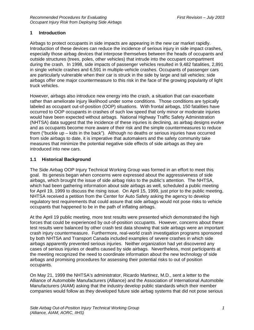
Airbags to protect occupants in side impacts are appearing in the new car market rapidly. Introduction of these devices can reduce the incidence of serious injury in side impact crashes, especially those airbag devices that interpose themselves between the heads of occupants and outside structures (trees, poles, other vehicles) that intrude into the occupant compartment during the crash. In 1998, side impacts of passenger vehicles resulted in 9,482 fatalities, 2,891 in single vehicle crashes and 6,591 in multiple-vehicle crashes. Occupants of passenger cars are particularly vulnerable when their car is struck in the side by large and tall vehicles; side airbags offer one major countermeasure to this risk in the face of the growing popularity of light truck vehicles.
However, airbags also introduce new energy into the crash, a situation that can exacerbate rather than ameliorate injury likelihood under some conditions. Those conditions are typically labeled as occupant out-of-position (OOP) situations. With frontal airbags, 150 fatalities have occurred to OOP occupants in crashes of such low speed that only minor or moderate injuries would have been expected without airbags. National Highway Traffic Safety Administration (NHTSA) data suggest that the incidence of these injuries is declining, as airbag designs evolve and as occupants become more aware of their risk and the simple countermeasures to reduce them (“buckle up – kids in the back”). Although no deaths or serious injuries have occurred from side airbags to date, it is imperative that automakers and the safety community take measures that minimize the potential negative side effects of side airbags as they are introduced into new cars.
1.1 Historical Background
The Side Airbag OOP Injury Technical Working Group was formed in an effort to meet this goal. Its genesis began when concerns were expressed about the aggressiveness of side airbags, which brought the issue of side airbag risks to the public’s attention. The NHTSA, which had been gathering information about side airbags as well, scheduled a public meeting for April 19, 1999 to discuss the rising issue. On April 15, 1999, just prior to the public meeting, NHTSA received a petition from the Center for Auto Safety asking the agency to develop regulatory test requirements that could assure that side airbags would not pose risks to vehicle occupants that happened to be in the path of inflating airbags.
At the April 19 public meeting, more test results were presented which demonstrated the high forces that could be experienced by out-of-position occupants. However, concerns about these test results were balanced by other crash test data showing that side airbags were an important crash injury countermeasure. Furthermore, real-world crash investigation programs sponsored by both NHTSA and Transport Canada included examples of severe crashes in which side airbags apparently prevented serious injuries. Neither organization had yet discovered any cases of serious injuries or deaths caused by side airbags. Nevertheless, most participants at the meeting recognized the need to coordinate information about the new technology of side airbags and promising procedures for assessing their potential risks to out of position occupants.
On May 21, 1999 the NHTSA’s administrator, Ricardo Martinez, M.D., sent a letter to the Alliance of Automobile Manufacturers (Alliance) and the Association of International Automobile Manufacturers (AIAM) asking that the industry develop public standards which their member companies would follow as they developed future side airbag systems that did not pose serious

Recommended Procedures for Evaluating First Revision – July 2003 Occupant Injury Risk from Deploying Side Airbags
Side Airbag Out-of-Position Injury Technical Working Group 2 (Alliance, AIAM, AORC, IIHS)
injury risks to vehicle occupants. Dr. Martinez also indicated it was important that the deliberations of the industry be:
• Comprehensive of the hardware and risks involved,
• Open and inclusive of different interest groups, and
• Timely.
In response, Alliance and AIAM asked the Insurance Institute for Highway Safety (IIHS) and the Automotive Occupant Restraints Council (AORC) to join them in sponsoring a technical working group comprised of crash safety and biomechanics experts to develop recommended procedures and performance requirements. Inclusion of AORC assured that the airbag supplier industry, which has a separate body of expertise, had a significant voice in the deliberations. IIHS was asked to chair the technical working group, in part because of its involvement in the analysis of frontal airbag out-of-position problems and because of independence from the auto industry and suppliers.
The first meeting of the Side Airbag OOP Injury Technical Working Group (TWG) was held in the Detroit area, Michigan, on July 21, 1999. Organizations and companies represented at that meeting and subsequent meetings included Alliance; AIAM; AORC; Autoliv; BMW; Bosch; Breed; DaimlerChrysler; Delphi; Ford; General Motors; Honda; Hyundai; IIHS; Dale Kardos and Associates; Mazda; Mitsubishi; Nissan; Porsche; Simula; Subaru; Takata; Toyota; TRW; and Volkswagen. Thus, automakers and airbag suppliers were represented. In addition, the TWG invited NHTSA and Transport Canada to attend the meetings, so that the knowledge of these two government organizations could inform the deliberations. Finally, Nationwide Insurance and George Washington University were included in the working group because of technical background and ties to other consumer information and testing organizations. Thus, participation in the TWG was as broad as possible, with the provision that participants outside the involved industries should have technical backgrounds that allow them to contribute to the technical discussions. Although not members of the TWG, Erika Jones of Mayer, Brown, and Platt (at the request of the Alliance), and Charles Lockwood of AIAM were present for some meetings to provide advice on antitrust and other legal questions that might arise from the activities of the TWG.
1.2 Information Considered by the Technical Working Group
The deliberations of the TWG benefited greatly from the expertise of its membership.
• Members serving on Working Group 3 of the International Organization for Standardization (ISO) Technical Committee 22, Subcommittee 10, which also has been considering procedures for evaluation of side airbags, kept the TWG apprised of parallel activities there. The preliminary work of the ISO Group provided the TWG with a head start on its consideration of test procedures. However, based on information provided the TWG, primarily test data from Transport Canada, several test positions were replaced with new positions that seemed both more realistic and more likely to reveal potentially aggressive side airbags. It is the understanding of the TWG that the ISO test procedures (TR 14933) have been modified to parallel the procedures recommended here.
Recommended Procedures for Evaluating First Revision – July 2003 Occupant Injury Risk from Deploying Side Airbags
Side Airbag Out-of-Position Injury Technical Working Group 3 (Alliance, AIAM, AORC, IIHS)
As part of the ISO Working Group 3 activities, several auto manufacturers have been conducting tests of different child dummies. Results of that testing were important in the TWG’s choice and specification of test dummies in its recommendations.
• Airbag supplier companies updated the TWG on their efforts to develop side airbags that meet the conditions being considered. One important implication of their information concerns the inherent relationship between the expected effectiveness of side airbags in serious crashes and the risk of OOP injury. Suppliers indicated they were developing side airbag prototypes that satisfied the OOP test criteria, but these airbags were clearly lower in power. There were no estimates as to the degree to which side airbag effectiveness was compromised, however, because no comparative tests were being conducted. According to suppliers, they are being asked to demonstrate only that new side airbag designs will produce good scores in the FMVSS 214 compliance test or the Lateral Impact New Car Assessment Program (LINCAP), in addition to satisfying the OOP tests.
Another important issue addressed by the suppliers’ data is that of test-to-test repeatability. High repeatability (or low variability) is necessary for airbag system developers to be confident that low scores on one test are predictive of low scores on subsequent tests. The higher the variability, the harder it is to have confidence in the performance of a system regarding a particular injury criterion. Supplier information suggests that some of the neck injury tests included in the current recommendations have relatively low repeatability, meaning that it would be necessary to design well below any selected injury threshold if a manufacturer wanted to assure that most airbags in mass production will meet the criterion. A point frequently emphasized by suppliers is that setting injury risk targets very low for OOP testing could greatly reduce the effectiveness of side airbags in real crashes, because the energy levels will have been set very low.
• The NHTSA reported on its Special Crash Investigations that involved side airbag vehicles. Following the experience with frontal airbags, the agency has maintained a concentrated effort to monitor the real-world experience with side airbags in order to be aware as early as possible of any untoward incidents. As of October, their program had investigated 37 crashes of vehicles with side airbags. Those investigations indicated that the side airbags already on the road at this time are performing well in the real world. Side airbags appeared to have prevented serious or fatal injury in a number of cases, including two where children were present. So far, no fatal injuries have been attributed to occupant interaction with side airbags; the cause of all fatal injuries in these side impacts has been severe intrusion. One serious injury, that to a 76 year old male driver, appears to have been caused by the side airbag, although there is continuing discussion about the case with the CIREN team that initiated the investigation. Side airbags are causing some injuries, but these tend to be minor or moderate. Overall, real-world experience has shown no serious problem with side airbags at this time; however, the number of deployment incidents is still quite small.
• Transport Canada has performed numerous crash tests and static side airbag deployment tests to study both out of position injury risk and the effectiveness of side airbags in severe side impacts. Based on their data, the TWG decided to replace two of the child OOP tests that had been proposed initially by ISO Working Group 3 with two tests that Transport Canada had developed. These tests, which address the OOP injury risk from side airbags that deploy from seat backs, appeared to adopt realistic risk positions and had been carefully specified by Transport Canada.

Recommended Procedures for Evaluating First Revision – July 2003 Occupant Injury Risk from Deploying Side Airbags
Side Airbag Out-of-Position Injury Technical Working Group 4 (Alliance, AIAM, AORC, IIHS)
Transport Canada has also conducted a number of full-scale side impact crash tests of vehicles with side airbags. These tests, in which the side airbag car is struck in the side by a utility vehicle, show impressive performance of the systems. In one test, a child dummy seated in the rear seat of a vehicle equipped with rear seat side airbags appeared to receive good protection from the side airbag, which prevented the child dummy’s head from contacting the stiff structure of the rear door.
• Recognized world leaders in the specification and quantification of injury risk from forces experienced during car crashes participated in the TWG. One of the difficulties faced by the TWG was to specify methods of testing for injury risk with dummies that were not designed in anticipation of the test conditions. For example, several of the recommended tests use frontal crash test dummies to assess risk from airbags that are more likely to deploy into the side of a human. The presence of these experts allowed the TWG to consider thoughtfully the problems in using these dummies and to reach reasonable recommendations for their use in assessing the risk of OOP injury from side airbags.
2 Scope of the Recommendations
Side airbags are inflatable devices intended to help reduce the crash injury risk of vehicle occupants adjacent to the struck side of the vehicle. Side airbags work by interposing an inflatable cushion between vehicle occupants and the vehicle’s side structure, which is pushed into the occupant by the striking vehicle or stationary roadside object (e.g. tree or pole). During the inflation process, an airbag releases considerable energy and, as a result, substantial forces can be developed between the deploying airbag and the nearby occupant. The interaction forces may be greater than intended by the airbag designer when the seat occupant or part of the seat occupant blocks the path of the inflating airbag. This situation may occur for a normally seated occupant whose outboard arm would be near a side airbag. Normally seated occupants may also be forced out-of-position by pre-crash events such as braking or hard maneuvering. Finally, some vehicle occupants drive or ride in positions different from those considered normal. A passenger sleeping with his/her head against the vehicle side, for example, may experience side airbag forces different from a normally seated passenger. The TWG recognizes these as circumstances to be considered in assessing side airbag systems. Other circumstances could also occur that are beyond the consideration of this TWG. For example, unrestrained occupants in a complex rollover crash may achieve positions unanticipated by these recommended procedures. However, the TWG does not believe the circumstances of this group should unnecessarily restrict the availability of side airbags to protect the remainder of the population.
This report describes the test devices (dummies), instrumentation, test procedures, and performance guidelines that should be used for assessing the injury risk of interactions between a deploying side airbag and a vehicle occupant. They do not address the issue of secondary impacts because the TWG believes the primary risk occurs during interaction with the side airbag. The test procedures are sufficiently broad to cover airbags which deploy from the door or side trim panel, the armrest, the seat back or cushion, the roof support pillars or roof rail area as well as occupants ranging in size from young children through adults. Most of the performance criteria are established to assure that the risks of life-threatening injuries to the head, neck, thorax and abdomen are low, but they also include criteria that minimize the risks of less serious injuries to the arm and pelvis. The test procedures described in this report provide as comprehensive an evaluation as possible for current state-of-the-art airbag designs. However, only sound engineering judgment can guarantee the comprehensive evaluation of

Recommended Procedures for Evaluating First Revision – July 2003 Occupant Injury Risk from Deploying Side Airbags
Side Airbag Out-of-Position Injury Technical Working Group 5 (Alliance, AIAM, AORC, IIHS)
any design. Additional tests, with slight variations of the recommended dummy positions, may be needed to ensure the robustness of the occupant interaction measurements.
2.1 Issues Not Addressed by the Technical Working Group
The TWG agreed with NHTSA that its deliberations should have a timely conclusion. To that end, the focus was on assuring that all those involved in the development of side airbags evaluated the potential risk according to the best knowledge of the industry. To achieve this focus, it was agreed that the TWG would not address several important issues:
• Methods for assessing the effectiveness of side airbags. This issue was outside the scope of the TWG’s mission, described above. However, the TWG notes that methods to evaluate the effectiveness of side airbags have been described elsewhere and include vehicle crash tests and impact simulation.
• Schedules for implementation of the recommended evaluation procedures by individual manufacturers. It is expected that all side airbag systems currently under development or those developed in the future will be designed according to the recommended procedures. While the real-world experience with side airbags to date has been very positive, there have not been enough deployments to assess the OOP injury risk of side airbags from accident data. The majority view of the TWG is that new systems should be designed according to these recommendations for further limiting out-of-position occupant injury risk largely because new technology is emerging that is expected to meet the guidelines while still providing effective side impact protection. Thus, new systems should be designed according to these recommendations for the simple reason that they now can be. This does not mean that older systems pose an unreasonable risk.
• Dissemination of information about out of position injury risk and compliance with the recommendations. The TWG recognizes that there is considerable public interest in the potential risk of side airbags to out-of-position occupants. However, communicating the actual risk of out-of-position injury in a meaningful way is complex, and this issue falls outside the expertise of the TWG. Moreover, there is likely to be variation in the degree to which these recommendations will be applied to side airbag systems that are already in vehicles, so this issue must be addressed by individual manufacturers.
3 Recommendations
The recommendations of the TWG address three substantive areas:
• The tools or test devices (crash test dummies) best suited for assessing injury risk from the close-range deployment of side airbags.
• Performance criteria against which to assess the injury risk indicated by the forces measured on the test devices.
• A standard set of test procedures (occupant positions) for assessing side airbag inflation-injury risk associated with various side airbag designs.
3.1 Test Devices
Recommended Procedures for Evaluating First Revision – July 2003 Occupant Injury Risk from Deploying Side Airbags
Side Airbag Out-of-Position Injury Technical Working Group 6 (Alliance, AIAM, AORC, IIHS)
The Side Airbag Out-of-Position Injury Technical Working Group focused principally on the risk of injury to small women, adolescents, and children. Even these occupants have low risk of injury from side airbag systems because the small size of side airbags means that occupants must be in the deployment path and near the module when the airbags deploy. Larger adults and infants are expected to be at even lower risk due to size and/or position in the vehicle seat. Given generally lower injury risk as occupant size increases, the small female should experience the maximum risk faced by an adult. For infants and toddlers (1-2 years), it is expected that the majority will increasingly be restrained in appropriate child restraints. The locations of these restraints place them out of the path of deploying side airbags.
These observations led the Technical Working Group (TWG) to conclude that the risk of side airbag inflation injury can be assessed using dummies representing the small female (and adolescents), the 6-year-old child, and the 3-year-old child. However, the TWG encourages vehicle manufacturers and their suppliers to verify whether these conclusions are appropriate for a given vehicle configuration. If a particular system places a larger adult’s head nearer the airbag deployment area than achieved by the small female or places a restrained child in a child seat in the deployment path, then this new risk should be assessed.
In assessing OOP injury risk, the TWG is recommending the use of child dummies developed for frontal impact testing and a small adult dummy developed for side impact testing. In reality, OOP injury risk can occur from forces applied in many directions – frontal, lateral, from the rear, from above – directions for which these dummies may not provide direct injury measures. There are relatively few test devices available for assessing some of these injury risks (for example, lateral forces or forces from the rear). Nevertheless, the TWG has concluded that appropriate positioning of the dummies that are available, such that the force transducers are oriented as designed with respect to the direction of force from the deploying airbags, can provide meaningful assessment of OOP injury risk. This conclusion reflects, in part, the fact that some of the risk will occur to occupants whose position in the vehicle exposes them to the types of forces that the dummies were designed to measure (i.e., frontal forces for frontal dummies). It also reflects the fact that each side airbag system will be subject to multiple tests. This should become more apparent as the reader considers the array of tests described in Section 3.3.
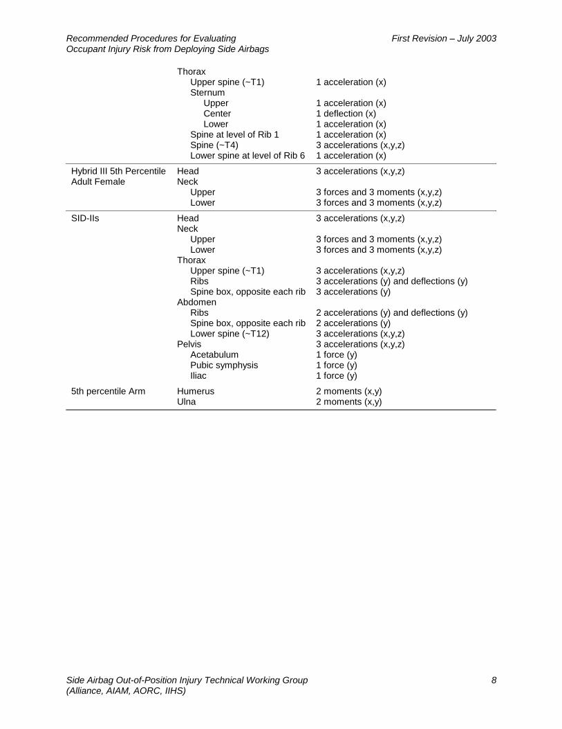
The test dummies recommended for use at this time by the TWG are described in the following sections. They are also listed In Table 1, which includes an indication of the required instrumentation to measure the injury risks specified elsewhere in this document.
3.1.1 Hybrid III 3-Year-Old Child Dummy
This dummy represents an average 3-year-old-child and was developed for evaluation of child restraint systems and frontal impact countermeasures. The dummy’s specifications are described in SAE Engineering Aid 31 and 49 CFR Part 572 Subpart P. The Q3 dummy, developed by TNO, also was considered by the TWG. The Q3 was supposedly designed to have both front and lateral biofidelity. However, testing of the Q3 by members of the TWG showed that it lacks the necessary durability and repeatability to be used in evaluating side airbag OOP injury risk, and its lateral impact biofidelity is no better than the Hybrid III 3-year-old child dummy. As a result, the TWG recommends using the Hybrid III 3-year-old dummy. This is consistent with the current recommendation of ISO/TC22/SC12/WG5.
3.1.2 Hybrid III 6-Year-Old Child Dummy

Recommended Procedures for Evaluating First Revision – July 2003 Occupant Injury Risk from Deploying Side Airbags
Side Airbag Out-of-Position Injury Technical Working Group 7 (Alliance, AIAM, AORC, IIHS)
This dummy represents an average 6-year-old child and was developed for evaluation of child restraint systems and frontal impact countermeasures. The dummy’s specifications are described in SAE Engineering Aid 29 (1998) and 49 CFR Part 572 Subpart N. The Hybrid III 6-year old is the only 6-year old child dummy available at this time. The TWG believes its suitability is similar to that of the Hybrid III 3-year old dummy. However, the 6-year old dummy does require the development of a neck shield because of a non-humanlike junction at the back of the head and the neck in which the inflating airbag could become partially trapped. This junction could produce nonbiofidelic load patterns on the dummy, particularly the neck transducers.
Use of the Hybrid III 6-year old dummy is consistent with the recommendation of ISO/TC22/SC12/WG5.
3.1.3 SID-IIs
This dummy represents a 5th percentile adult female as well as typical 12-13-year-old adolescents. It was designed specifically for the evaluation of side impact countermeasures; hence, it is normally equipped with laterally oriented measuring devices. Daniel et al (1995) describes the dummy’s specifications. Use of the SID-IIs is consistent with the recommendation of ISO/TC22/SC12/WG5.
3.1.4 Hybrid III 5th Percentile Adult Female Dummy
This dummy represents a 5th percentile adult female as well as typical 12-13-year-old adolescents. It was designed for the evaluation of front impact countermeasures. The dummy’s specifications are described in SAE Engineering Aid 25 (1994) and 49 CFR Part 572 Subpart O. In the context of these recommendations, the Hybrid III small female dummy is a suitable substitute for the SID-IIs in tests of roof-rail-mounted airbags. For roof-rail airbags, the principal injury risks concern the head and neck, which are identical for SID-IIs and the Hybrid III 5th percentile female. Tests of systems that pose a risk of injury to the thorax, abdomen, or pelvis should be tested with the SID-IIs.
Table 1 Test Devices (Dummies) and Recommended Instrumentation for Assessing OOP Injury Risk for Side Airbags
Dummy Body Region Instrumentation Measure Head 3 accelerations (x,y,z) Neck
Upper Lower
3 forces and 3 moments (x,y,z) 3 forces and 3 moments (x,y,z)
Hybrid III 3-Year-Old Child Dummy
Thorax Upper spine (~T1) Sternum
Upper Center Lower
Spine (~T4) Spine at level of Rib 3 Lower spine (~T12)
3 accelerations (x,y,z) 1 acceleration (x) 1 deflection (x) 1 acceleration (x) 3 accelerations (x,y,z) 1 acceleration (x) 3 accelerations (x,y,z)
Head 3 accelerations (x,y,z) Hybrid III 6-Year-Old Child Dummy Neck
Upper Lower
3 forces and 3 moments (x,y,z) 3 forces and 3 moments (x,y,z)
Recommended Procedures for Evaluating First Revision – July 2003 Occupant Injury Risk from Deploying Side Airbags
Side Airbag Out-of-Position Injury Technical Working Group 8 (Alliance, AIAM, AORC, IIHS)
Thorax Upper spine (~T1) Sternum
Upper Center Lower
Spine at level of Rib 1 Spine (~T4) Lower spine at level of Rib 6
1 acceleration (x) 1 acceleration (x) 1 deflection (x) 1 acceleration (x) 1 acceleration (x) 3 accelerations (x,y,z) 1 acceleration (x)
Hybrid III 5th Percentile Adult Female
Head Neck
Upper Lower
3 accelerations (x,y,z) 3 forces and 3 moments (x,y,z) 3 forces and 3 moments (x,y,z)
Head 3 accelerations (x,y,z) Neck
Upper Lower
3 forces and 3 moments (x,y,z) 3 forces and 3 moments (x,y,z)
Thorax Upper spine (~T1) Ribs Spine box, opposite each rib
3 accelerations (x,y,z) 3 accelerations (y) and deflections (y) 3 accelerations (y)
Abdomen Ribs Spine box, opposite each rib Lower spine (~T12)
2 accelerations (y) and deflections (y) 2 accelerations (y) 3 accelerations (x,y,z)
SID-IIs
Pelvis Acetabulum Pubic symphysis Iliac
3 accelerations (x,y,z) 1 force (y) 1 force (y) 1 force (y)
5th percentile Arm Humerus Ulna
2 moments (x,y) 2 moments (x,y)
Recommended Procedures for Evaluating First Revision – July 2003 Occupant Injury Risk from Deploying Side Airbags
Side Airbag Out-of-Position Injury Technical Working Group 9 (Alliance, AIAM, AORC, IIHS)
3.1.5 Instrumented Arm for 5th Percentile Adult Female Dummy
The instrumented arm for small female dummies was developed through the cooperation of the SAE Human Biomechanics and Simulation Standards Committee; Mechanical Simulation Subcommittee and Robert A, Denton, Inc. It is designed to fit both the Hybrid III 5th percentile adult female dummy and the SID-IIs.
3.1.6 Dummy Preparation for Side Airbag Tests
3.1.6.1 General
The dummy should be in good condition and able to meet its performance certification requirements. The dummy shall be dressed in tight fitting cotton knit shirt and pants. The skullcap seam shall be taped with 4mm or electrical tape to prevent the airbag from getting caught in the seam. The dummy’s head skin shall be cleaned with alcohol and dusted with baby powder to achieve acceptable frictional characteristics.
3.1.6.2 Dummy Test Temperature
The test dummy temperature should be within a temperature range of 20.6-22.2 °C at a relative humidity of 10-70 percent after a soak period of at least 4 hours prior to its application in a test, or that specified for the dummy by the dummy manufacturer.
3.1.6.3 Instrumentation
3.1.6.3.1 General
Measurements needed for the assessment of airbag-inflation injury risk using each of the approved anthropomorphic test devices are shown in Table 1. All measurements should be recorded and filtered according to the latest version SAE J211. These measurements should be recorded continuously and synchronously throughout the tests defined in Section 3.3, so that injury measures may be calculated. The TWG recommends that sternum and rib deflection rate be calculated from the integration of the difference between rib/sternum and spine accelerations. Differentiation of displacement measures is an acceptable alternative. It should be noted that either method can produce spurious rates depending on the amount of noise in the original signals and the methods of integration and differentiation. Appendix B contains the recommended procedure for the calculation using the difference between rib/sternum and spine accelerations.
Dummy interactions with the side airbags should also be monitored by high-speed cameras (or equivalent video equipment) operating at a minimum speed of 1000 frames per second (3000 fps is recommended). The cameras should be positioned so that the field-of-view encompasses the test setup and includes the anticipated movement of the dummy during the test.
3.1.6.3.2 Electrical Grounding
The test dummy, vehicle, and all related instrumentation must be grounded. The test dummy shall be grounded with cables attached to the dummy’s head, thorax, abdomen, and pelvis, which shall be connected to earth ground during all testing. Between tests, the dummy may be sprayed with an anti-static spray. These are both very important due to the high likelihood for electrostatic discharges as a result of the inflating airbag.
3.2 Dummy Injury Values
Recommended Procedures for Evaluating First Revision – July 2003 Occupant Injury Risk from Deploying Side Airbags
Side Airbag Out-of-Position Injury Technical Working Group 10 (Alliance, AIAM, AORC, IIHS)
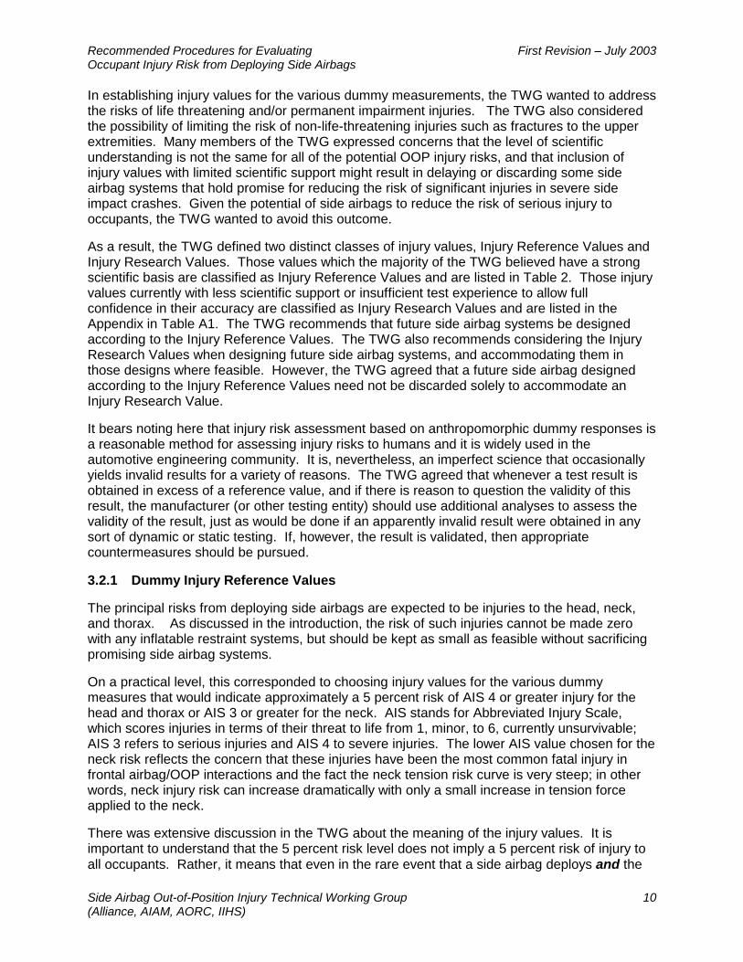
In establishing injury values for the various dummy measurements, the TWG wanted to address the risks of life threatening and/or permanent impairment injuries. The TWG also considered the possibility of limiting the risk of non-life-threatening injuries such as fractures to the upper extremities. Many members of the TWG expressed concerns that the level of scientific understanding is not the same for all of the potential OOP injury risks, and that inclusion of injury values with limited scientific support might result in delaying or discarding some side airbag systems that hold promise for reducing the risk of significant injuries in severe side impact crashes. Given the potential of side airbags to reduce the risk of serious injury to occupants, the TWG wanted to avoid this outcome.
As a result, the TWG defined two distinct classes of injury values, Injury Reference Values and Injury Research Values. Those values which the majority of the TWG believed have a strong scientific basis are classified as Injury Reference Values and are listed in Table 2. Those injury values currently with less scientific support or insufficient test experience to allow full confidence in their accuracy are classified as Injury Research Values and are listed in the Appendix in Table A1. The TWG recommends that future side airbag systems be designed according to the Injury Reference Values. The TWG also recommends considering the Injury Research Values when designing future side airbag systems, and accommodating them in those designs where feasible. However, the TWG agreed that a future side airbag designed according to the Injury Reference Values need not be discarded solely to accommodate an Injury Research Value.
It bears noting here that injury risk assessment based on anthropomorphic dummy responses is a reasonable method for assessing injury risks to humans and it is widely used in the automotive engineering community. It is, nevertheless, an imperfect science that occasionally yields invalid results for a variety of reasons. The TWG agreed that whenever a test result is obtained in excess of a reference value, and if there is reason to question the validity of this result, the manufacturer (or other testing entity) should use additional analyses to assess the validity of the result, just as would be done if an apparently invalid result were obtained in any sort of dynamic or static testing. If, however, the result is validated, then appropriate countermeasures should be pursued.
3.2.1 Dummy Injury Reference Values
The principal risks from deploying side airbags are expected to be injuries to the head, neck, and thorax. As discussed in the introduction, the risk of such injuries cannot be made zero with any inflatable restraint systems, but should be kept as small as feasible without sacrificing promising side airbag systems.
On a practical level, this corresponded to choosing injury values for the various dummy measures that would indicate approximately a 5 percent risk of AIS 4 or greater injury for the head and thorax or AIS 3 or greater for the neck. AIS stands for Abbreviated Injury Scale, which scores injuries in terms of their threat to life from 1, minor, to 6, currently unsurvivable; AIS 3 refers to serious injuries and AIS 4 to severe injuries. The lower AIS value chosen for the neck risk reflects the concern that these injuries have been the most common fatal injury in frontal airbag/OOP interactions and the fact the neck tension risk curve is very steep; in other words, neck injury risk can increase dramatically with only a small increase in tension force applied to the neck.
There was extensive discussion in the TWG about the meaning of the injury values. It is important to understand that the 5 percent risk level does not imply a 5 percent risk of injury to all occupants. Rather, it means that even in the rare event that a side airbag deploys and the
Recommended Procedures for Evaluating First Revision – July 2003 Occupant Injury Risk from Deploying Side Airbags
Side Airbag Out-of-Position Injury Technical Working Group 11 (Alliance, AIAM, AORC, IIHS)
occupant is as severely out of position as specified in these tests and if the dummy responses are below the specified injury values, the risk of serious or severe injury from the airbag is very low. Thus, the actual risks to occupants from the deploying side airbags that produce dummy responses that are at or below the proposed Injury Reference Values are exceedingly small.
The Injury Reference Values recommended by the TWG are summarized in Table 2. Details about their derivation are given in the following sections.
3.2.1.1 Head Injuries
The most widely accepted measure of head injury risk is the Head Injury Criterion (HIC). The recommended Injury Reference Values for HIC are the same as given in the Alliance (1999) recommendation to NHTSA for the OOP assessment of frontal airbags. For the average sized adult male, HIC of 700 corresponds approximately to a 5 percent risk of an AIS 4 or greater injury (Mertz et al., 1997). This value was scaled to give the Injury Reference Values for the other size occupants noted in Table 2. The scaling method used takes into account size and brain tissue strength variation with age as described by Mertz et al. (1997). For all dummy sizes, the time interval of the search for the maximum HIC value should not exceed 15 ms. The TWG agreed that the HIC values in Table 2 should be treated as Injury Reference Values since their basis is an injury risk curve.
Table 2 Dummy Injury Reference Values for Out-of-Position Testing of Side Airbags Dummy
Body Region/Injury Measure
Hybrid III 3-Year-Old
Child
Hybrid III 6-Year-Old
Child
Hybrid III Small
Female SID-IIs Head
15 ms HIC 570 723 779 779
Upper Neck Nij 1 1 1 1 Intercepts
FT (N) 2120 2800 3880 3880 FC (N) 2120 2800 3880 3880 MF (Nm) 68 93 155 155 ME (Nm) 27 37 61 61
Tension (N) 1130 1490 2070 2070 Compression (N) 1380 1820 2520 2520
Thorax
Deflection (mm) 36 40 34 Deflection rate (m/s) 8.0 8.5 8.2

Recommended Procedures for Evaluating First Revision – July 2003 Occupant Injury Risk from Deploying Side Airbags
Side Airbag Out-of-Position Injury Technical Working Group 12 (Alliance, AIAM, AORC, IIHS)
3.2.1.2 Neck Injuries
Based on the frontal airbag OOP injury data, the TWG believes neck injuries will be the most critical OOP injury risk from side airbags. Experience with frontal airbags indicates that rupture of the connective tissues between the head and neck (occipital condyles – atlas region) is a primary cause of the fatalities observed among OOP children and adults. Accordingly, the TWG considered a number of neck injury indicators that can be measured at the upper neck load cells of the dummy necks.
One approach is to impose limits on the peak force and moment values that are measured by the upper neck load transducer located at the dummy’s head/neck interface, occipital condyles. Limit values for these measurements were proposed by AAMA (1998) for OOP assessment of frontal airbags.
A second approach is to place limits on an index. The Nij combines the effects of the forces and moments as was proposed by Prasad and Daniel (1984) for tension and extension moment. In its rulemaking activities regarding the assessment of OOP injury risk from frontal airbags, NHTSA proposed using the Nij concept and extended the analysis to include the combinations of tension-flexion, compression-flexion, and compression-extension. In its comments on the NHTSA proposal, the Alliance (1999) developed injury risk curves for the combined effect of tension-extension moment based on its re-analysis of the animal injury/dummy response correlation data of Mertz et al. (1982) and Prasad and Daniel (1984). The Alliance recommended setting the limit for tension-extension moment at 2 percent risk of AIS ≥3 neck injury. The 5 percent risk line was not chosen as the limit line because 5 animals with AIS ≥3 neck injury were below the 5 percent limit line. There were no animals with AIS ≥3 neck injury below the proposed 2 percent limit line.
In addition, the Alliance was concerned that the Nij concept allowed high axial forces when the bending moments were low. Because the most sensitive indicator of animal neck injury was peak neck tension (Mertz et al., 1997), the Alliance proposed to limit peak tension and peak compression. The limits for peak neck tension were set at 3 percent risk of AIS ≥3 neck injury. The limits for peak neck compression were set at the currently used Injury Assessment Reference Values (IARV). These peak force limits are the same as those proposed by AAMA (1998). NHTSA agreed with the Alliance proposal and incorporated these limits into FMVSS 208 for regulating the OOP performance of frontal airbags.
The TWG reviewed the two approaches and chose to use the combined index, Nij=1 and the peak force limits, that were proposed by the Alliance and are now the upper neck limit requirement of FMVSS 208 for OOP regulation of frontal airbags. The intercept values of the Nij limit lines and the peak tension and peak compression limit values are given in Table 2.
Some manufacturers and suppliers have expressed concern that extension and flexion bending moments measured on a dummy in a given test may not always reflect neck injury risk to the corresponding human. As noted above, injury risk assessment on anthropomorphic dummies is a reasonable surrogate for assessing injury risks to humans and it is widely used in the automotive engineering community. It is, nevertheless, an imperfect science that occasionally yields invalid results for a variety of reasons. For this reason, the TWG agreed in general that whenever a test result is obtained in excess of a reference value, and if there is reason to question the validity of this result, the manufacturer (or other testing entity) should use additional analyses to assess the validity of the result. If, however, the result is validated, then appropriate countermeasures should be pursued. Therefore, if a manufacturer or other testing

Recommended Procedures for Evaluating First Revision – July 2003 Occupant Injury Risk from Deploying Side Airbags
Side Airbag Out-of-Position Injury Technical Working Group 13 (Alliance, AIAM, AORC, IIHS)
entity obtains an extension or flexion bending moment in excess of the reference values and has reason to question the validity of that result, the response should be the same as the general guidance adopted by the TWG; namely, to use additional analyses to assess the validity of the result and, if the result is validated, to take appropriate actions.
3.2.1.3 Thoracic Injuries
The TWG recommends that chest compression and compression rate be treated as thoracic Injury Reference Values for OOP testing of side airbags. The Injury Reference Values for the 3-year-old and 6-year-old dummies are the same as those recommended by the AAMA (1998) for frontal airbag OOP testing and are based on research reported in Mertz et al. (1997). The peak compression Injury Reference Value for the SID-IIs was obtained by scaling the BioSID (50th percentile male side impact dummy) IARV (Mertz, 1993; NATO, 1996). The chest compression rate Injury Reference Value recommended for the SID-IIs is the same as the Hybrid III 5th percentile female sternal deflection rate associated with approximately a 5 percent risk of AIS 4+ thoracic injury in frontal impacts (AAMA, 1998; Mertz et al., 1997). The latter recommendation is based on animal tests that have shown that injury severities corresponding to thoracic compression rates are similar for frontal and side impacts (Mertz et al., 1982).
3.3 Test Procedures
Current systems of side airbags include at least one of three types of side airbags: those that deploy from the seat backs (seat-mounted), those that deploy from the door or rear quarter panel, typically just below the window sill (side-mounted), and those that deploy from the roof rail above the door (roof-mounted). The test positions to assess OOP injury risk for these different side airbag designs and/ or combinations of these designs are shown in Table 3. For each side airbag type, test positions have been suggested for each of the three test devices (3-year-old child, 6-year-old child, and small female/adolescent). The tests specified for the small female are relevant to driver and passenger seating positions fitted with side airbags, while those for the 3-year-old and 6-year-old child dummies are relevant only to passenger positions. If driver and passenger side airbag systems are mirror images of one another (front or rear seats), then specified tests need be conducted on only one side of the vehicle.
These static tests were developed to evaluate the inflation-injury risk of side airbags. The test dummy positions were chosen to block the deployment path of the deploying airbag and also to align the dummy’s measurement systems to measure the effects of the resulting dummy-airbag interaction. Evaluations should be conducted with representative seats and door trim panels located in the vehicle design position. Systems that include more than one type of airbag should be tested with all side airbags deployed according to the deployment strategy of the vehicle.
In general, these test positions have been chosen to represent nominal “worst case” occupant positions, relative to the side airbags. They represent potentially dangerous rather than common positions occurring among the traveling public. Each manufacturer should evaluate whether that is the case for their particular system and modify the test positions as appropriate. The TWG recommends that manufacturers assess whether additional OOP tests of their systems are appropriate that vary the test positions somewhat from those specified in these recommendations. Test data discussed during the TWG’s meetings show that even minor deviations in dummy positioning can greatly change the results of OOP testing. The positions recommended by the TWG provide a generalized point for evaluating side airbag OOP injury potential and each manufacturer must assess whether to vary from the specified procedures and whether additional
Recommended Procedures for Evaluating First Revision – July 2003 Occupant Injury Risk from Deploying Side Airbags
Side Airbag Out-of-Position Injury Technical Working Group 14 (Alliance, AIAM, AORC, IIHS)
testing is necessary for their system. Variations from the recommended positions should still be in a reasonable range that represents typical “worst case” conditions.
3.3.1 General Seat Preparation Procedure
The TWG emphasizes that these instructions apply to initial positioning efforts. Test engineers must determine if these instructions are consistent with their particular system and modify them as appropriate to meet the objectives of the individual test.
1. To aid dummy positioning, identify and mark the centerline of the seat back and seat cushion. For seat mounted airbag systems, draw a horizontal line on the seat corresponding to the top edge of the side airbag module.
2. Tests are to be conducted with the seat in the rearmost and lowest adjustment. The seat back should be adjusted to the manufacturer’s design angle or to achieve a torso angle of 25 degrees as measured on the SAE J826 H-Point machine. If any of these adjustments is found to interfere with the inflation of the airbag or with the stated test objective, then the seat track position and or seat back angle may be adjusted the minimum amount necessary to avoid obstruction and fulfill the required test objective with the seat still in a nominally normal position for travel.
3. The head restraint is adjusted to its full-down position.
4. The upper safety belt anchor is adjusted to its highest position. The seat belt may be taped to the B-pillar to avoid entanglement with the side airbag.
5. All windows on the tested (inflation) side of the vehicle should be in the closed position, unless otherwise specified.
3.3.2 Suppression Systems
Some manufacturers may choose to limit the risk of OOP injury risk through suppression systems. Suppression systems may deactivate the side airbags when occupants are too near the deployment area or when the occupants are particularly vulnerable to injury (i.e., small children). If a suppression system would deactivate the airbag in one or more of the test scenarios described in Sections 3.3.3 and following, those test scenarios need not be performed. However, the TWG notes that the manufacturer should review whether that particular scenario should be replaced with another. For example, a side airbag might be suppressed for a 3-year-old child but still be potentially injurious to a 6-year-old child in a position similar to that which had been intended to be tested with the dummy representing the 3-year-old child. In this case a similar test set-up using the 6-year-old dummy should be evaluated.

Recommended Procedures for Evaluating First Revision – July 2003 Occupant Injury Risk from Deploying Side Airbags
Side Airbag Out-of-Position Injury Technical Working Group 15 (Alliance, AIAM, AORC, IIHS)
Table 3 Recommended Test Procedures Section Test Position Body Region Airbag Designs
Monitored and of interest
Sea
t bac
k
Doo
r/ q
uart
er-p
anel
(Q
P)
Roo
f-ra
il
Roo
f-ra
il &
sea
t bac
k
Roo
f-ra
il &
doo
r/
quar
ter-
pane
l (Q
P)
3.3.3.1
Forward facing on booster seat
Head, neck
3.3.3.2
Rearward facing Head, neck, thorax
3.3.3.
3
Lying on seat, Head on armrest – for seat mounted bag
Head, neck *
3.3.3.4
Lying on seat – for seat mounted bag
Head, neck *
3.3.4.1
Outboard facing Head, neck, thorax
3.3.4.2
Inboard facing Head, neck
3.3.4.3
Lying on seat, Head on armrest – for door/QP mounted bag
Head, neck *
Hyb
rid
III 3
-Yea
r-O
ld
3.3.4.4 Lying on seat – for door/QP mounted bag
Head, neck *
3.3.3.5
Forward facing on booster seat
Head, neck
Hyb
rid
III
6-Y
ear-
Old
3.3.5.1
Inboard facing on booster seat
Head, neck
3.3.3.6
Inboard facing – for seat mounted bag
Head, neck, thorax, abdomen, pelvis
3.3.3.7
Arm on armrest with instrumented arm
Arm, forearm ** **
SID
-IIs
3.3.4.5 Forward facing
Head, neck, thorax, abdomen, pelvis
SID
-IIs
or
Hyb
rid
III
5th
3.3.5.2
Forward facing with raised seat
Head, neck

Recommended Procedures for Evaluating First Revision – July 2003 Occupant Injury Risk from Deploying Side Airbags
Side Airbag Out-of-Position Injury Technical Working Group 16 (Alliance, AIAM, AORC, IIHS)
3.3.5.3
Inboard facing with raised seat
Head, neck
*The chart shows for typical side airbag systems (in columns) the recommended tests (shaded cells in each column). Vehicles with more than one type of side airbag at a seating position should be evaluated using tests with all airbags deploying according to the deployment strategy of the vehicle. In tests identified by an asterisk (*), the evaluation can be based on thorax bag deployment alone, if the roof rail airbag would clearly not interact with the dummies. In tests of the arm injury potential (identified by **), the injury potential may be based on thorax bag deployment alone.

Recommended Procedures for Evaluating First Revision – July 2003 Occupant Injury Risk from Deploying Side Airbags
Side Airbag Out-of-Position Injury Technical Working Group 17 (Alliance, AIAM, AORC, IIHS)
3.3.3 Tests for Seat-Mounted Airbags
3.3.3.1 Forward Facing Hybrid III 3-Year-Old Child Dummy on Booster Block (Passenger Positions with Seat-Mounted Airbags)
Figure 3.3.3.1.1 Forward Facing Hybrid III 3-year-old Child Dummy on Booster Block
Leaning Against Door Trim Panel Test Objective: To maximize the head/neck interaction by aligning the neck with the top of the side airbag module.
Test Procedure: The booster foam block dimensions are 300 mm deep by 450 mm wide by 75 mm thick. The foam has a density of 40-80 g/l. A typical foam material is expanded polypropylene (EPP).
Verify that the seat has been positioned to 3.3.1. Locate and mark on the seat cushion two points for heel placement at 20-50 mm from the leading edge of seat cushion and 75 mm from the centerline on each side. Center the foam block on seat cushion so that it contacts the seat back bolsters. Do not tape or otherwise attach the booster to the seat. The dummy positioned in the vehicle is shown in Figure 3.3.3.1.1. Specific positioning instructions are as follows:
1. The dummy shall be dressed in tight fitting cotton knit shirt and pants. The skullcap seam shall be taped with 4 mm wide electrical tape to prevent the airbag from getting caught in the seam. The dummy’s head skin shall be cleaned with alcohol and dusted with baby powder to achieve acceptable frictional characteristics.
2. Seat the dummy on the outboard edge of foam block, aligning the upper spine with the deployment trajectory of the airbag, for example: the leading edge of the seat bolster or the airbag module. If the dummy upper spine can not be aligned due to interference with the pillar/ side trim adjust the seat track position accordingly.
3. Place the dummy’s head in between the seat bolster and pillar/side trim to minimize the fore-aft clearance between the neck and the seatback. The head should remain in its neutral orientation and should not be forced into flexion or extension.
4. Place heels at heel placement points (previously marked on seat cushion). 5. With feet held in position, slide pelvis forward and parallel to the centerline of the vehicle,
until the head/neck junction (i.e., lower edge of the skin at the base of the head) is aligned vertically with the top edge of the airbag module.
6. Reposition heels over placement points, if necessary.
Recommended Procedures for Evaluating First Revision – July 2003 Occupant Injury Risk from Deploying Side Airbags
Side Airbag Out-of-Position Injury Technical Working Group 18 (Alliance, AIAM, AORC, IIHS)
7. With the vehicle door closed and the dummy’s outboard arm raised (to clear armrest), slide the pelvis and upper torso outboard until pelvis or torso contact the door. The neck/torso junction may shift down no more than 20 mm during the process.
8. Place the outboard arm on the armrest. 9. Flex the inboard arm such that the upper arm contacts with the seatback and the fingertips
contact the booster seat. 10. Deploy the side airbag(s) and record the following dummy channels: head acceleration (Ax,
Ay, Az) and upper and lower neck forces and moments (Fx, Fy, Fz, Mx, My, Mz).

Recommended Procedures for Evaluating First Revision – July 2003 Occupant Injury Risk from Deploying Side Airbags
Side Airbag Out-of-Position Injury Technical Working Group 19 (Alliance, AIAM, AORC, IIHS)
3.3.3.2 Rearward Facing Hybrid III 3-Year-Old Child Dummy (Passenger Positions with Seat-Mounted Airbags)
Figure 3.3.3.2.1 Rearward Facing Hybrid III 3-Year-Old Child Dummy Leaning Against Door
Test Objective: To maximize chest interaction by aligning the sternum with the top of the seat-mounted side airbag module.
Test Procedure: Verify that the seat has been positioned to 3.3.1. The dummy positioned in the vehicle is shown in Figure 3.3.3.2.1. Specific positioning instructions are as follows:
1. The dummy shall be dressed in tight fitting cotton knit shirt and pants. The skullcap seam shall be taped with 4 mm wide electrical tape to prevent the airbag from getting caught in the seam. The dummy’s head skin shall be cleaned with alcohol and dusted with baby powder to achieve acceptable frictional characteristics.
2. Place the dummy along the outboard edge of the seat cushion, kneeling and facing rearward. Its feet may overhang the front edge of the seat cushion.
3. Align the vertical centerline of the dummy’s sternum as close as possible with the leading edge of the seat back bolster or forward most contour line. The sternum should contact the seat. If the dummy sternum cannot be aligned due to interference with the pillar adjust the seat track position to ensure that the test objective is met.
4. Place the dummy’s head in between the seat bolster and pillar/side trim to maximize contact between the sternum and the seatback. The head should remain in its neutral orientation and should not be forced into flexion or extension.
5. Position the outboard leg at the outboard edge of the seat cushion and parallel to the seat centerline. For seat cushions with bolsters, the outboard leg should be placed as close to the outboard edge of the seat cushion bolster as possible, while remaining on the cushion.
6. Slide the outboard knee and lower leg toward the seat bight (i.e., seat back/seat cushion junction) until the top edge of the upper rib is aligned horizontally with the top edge of the airbag module. The sternum should be in contact with the leading edge of the seat back bolster. In vehicles where the dummy fails to reach the top edge of the airbag module, place the outboard knee at the seat bight, at the outboard edge of the seat cushion.
7. Align the inboard leg such that it is parallel to the centerline of the seat cushion. Slide the inboard knee and lower leg towards the seat bight until a line drawn through both shoulder bolts is perpendicular to the vehicle centerline.
8. Rotate the inboard arm towards the seat back until the thumb contacts the seat back. 9. Rotate the outboard arm and hand to hang down as close to vertical as possible.
Recommended Procedures for Evaluating First Revision – July 2003 Occupant Injury Risk from Deploying Side Airbags
Side Airbag Out-of-Position Injury Technical Working Group 20 (Alliance, AIAM, AORC, IIHS)
10. Deploy the side airbag(s) and record the following dummy channels: head acceleration (Ax, Ay, Az), upper and lower neck forces and moments (Fx, Fy, Fz, Mx, My, Mz), chest acceleration (Ax, Ay, Az), mid-sternum deflection (Dx), upper and lower sternum accelerations (Ax) and upper and lower spine accelerations (Ax, Ay, Az). Sternum accelerations are measured so that, in combination with spine acceleration, they can be used to calculate the compression rate indicated by the sternum deflection.

Recommended Procedures for Evaluating First Revision – July 2003 Occupant Injury Risk from Deploying Side Airbags
Side Airbag Out-of-Position Injury Technical Working Group 21 (Alliance, AIAM, AORC, IIHS)
3.3.3.3 Hybrid III 3-Year-Old Child Dummy Lying on Seat with Head on Armrest (Passenger Positions with Seat-Mounted Airbags)
Figure 3.3.3.3.1 Hybrid III 3-Year-Old Child Dummy Lying Across Seat with Head on Door Trim Panel
Test Objective: To maximize the head interaction by aligning the head with the vertical centerline of the airbag module.
Test Procedure: A foam wedge, which is wide enough to support the dummy across the full width of its back (approximately 300 mm), is used to support the dummy’s weight. The remaining dimensions of the wedge should be chosen to allow the dummy’s head to touch the armrest without applying a significant downward force. The foam’s density should be 40-80 g/l. A typical foam material is expanded polypropylene (EPP).
Verify that the seat has been positioned to 3.3.1. The dummy’s position in the vehicle is shown in Figure 3.3.3.3.1. Specific positioning instructions are as follows:
1. The dummy shall be dressed in tight fitting cotton knit shirt and pants. The skullcap seam shall be taped with 4 mm wide electrical tape to prevent the airbag from getting caught in the seam. The dummy’s head skin shall be cleaned with alcohol and dusted with baby powder to achieve acceptable frictional characteristics.
2. Place the dummy on the seat lying on its back with its arms at its sides so that its rearmost arm contacts the seatback.
3. Bending the dummy at the waist, with the back of the head touching the armrest slide it inboard/outboard until the CG of the head aligns with the vertical centerline of the module (armrest contact must be maintained). Support the dummy’s back with a wedge-shaped foam block so that the head remains in a neutral position (i.e., head should not be forced into flexion or extension) and does not exert a significant downward force (< 5N) on the armrest.
4. Adjust the dummy’s arm closest to the front edge of the seat so that it is parallel to the torso and rests on the foam block with the fingertips just touching the seat cushion.
5. Adjust the rearmost upper arm to an orientation 45 degrees forward of the torso centerline and the forearm on the same side to an orientation 90 degrees to the upper arm.
6. Deploy the side airbag(s) and record the following dummy channels: head acceleration (Ax, Ay, Az) and upper and lower neck forces and moments (Fx, Fy, Fz, Mx, My, Mz).
Recommended Procedures for Evaluating First Revision – July 2003 Occupant Injury Risk from Deploying Side Airbags
Side Airbag Out-of-Position Injury Technical Working Group 22 (Alliance, AIAM, AORC, IIHS)
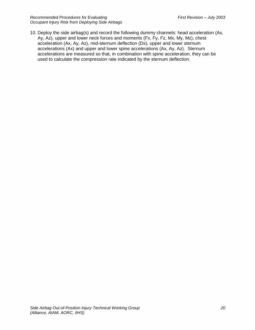
3.3.3.4 Hybrid III 3-Year-Old Child Dummy Lying on Seat (Passenger Positions with Seat-Mounted Airbags)
Figure 3.3.3.4.1 Hybrid III 3-Year-Old Child Dummy Lying Across Seat Test Objective: To maximize the head and neck interaction with the seat-mounted airbag by aligning the head with the vertical centerline of the seat-mounted airbag module.
Test Procedure: Verify that the seat has been positioned to 3.3.1. The dummy positioned in the vehicle is shown in Figure 3.3.3.4.1. Specific positioning instructions are as follows:
1. The dummy shall be dressed in tight fitting cotton knit shirt and pants. The skullcap seam shall be taped with 4 mm wide electrical tape to prevent the airbag from getting caught in the seam. The dummy’s head skin shall be cleaned with alcohol and dusted with baby powder to achieve acceptable frictional characteristics.
2. Place the dummy on the seat lying on its back with its arms at its sides so that its rearmost arm contacts the seatback.
3. Slide the dummy outboard until the CG of the head is aligned with the vertical centerline of the airbag module. Should the door/side trim interfere with the placement of the head then adjust the seat to ensure that the test objective is met.
4. If necessary, stabilize the dummy by placing a block of lightweight foam under the dummy’s legs.
5. Deploy the side airbag(s) and record the following dummy channels: head acceleration (Ax, Ay, Az) and upper and lower neck forces and moments (Fx, Fy, Fz, Mx, My, Mz).
Recommended Procedures for Evaluating First Revision – July 2003 Occupant Injury Risk from Deploying Side Airbags
Side Airbag Out-of-Position Injury Technical Working Group 23 (Alliance, AIAM, AORC, IIHS)
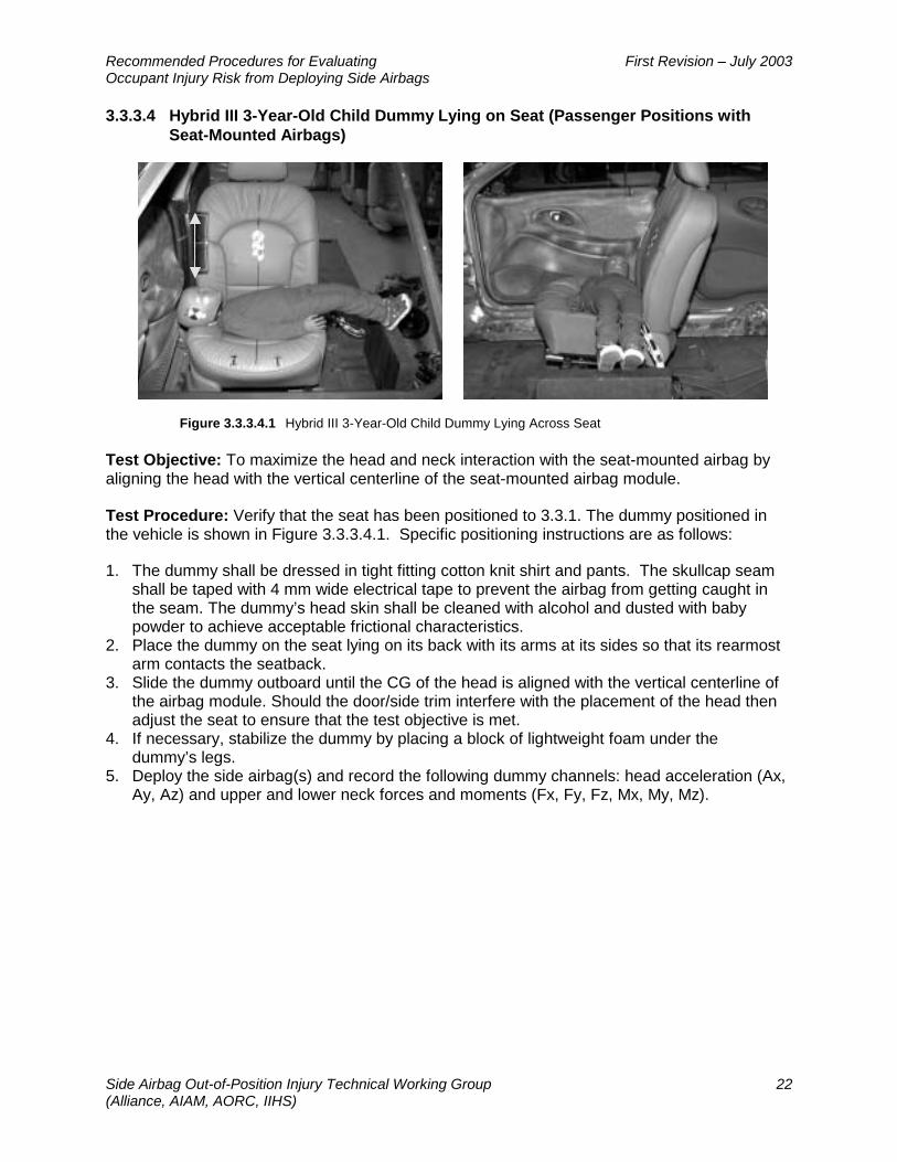
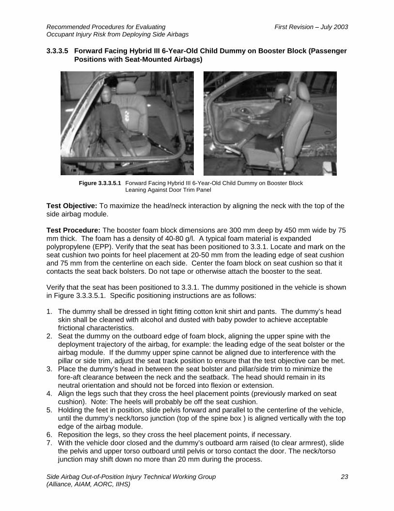
3.3.3.5 Forward Facing Hybrid III 6-Year-Old Child Dummy on Booster Block (Passenger Positions with Seat-Mounted Airbags)
Figure 3.3.3.5.1 Forward Facing Hybrid III 6-Year-Old Child Dummy on Booster Block
Leaning Against Door Trim Panel Test Objective: To maximize the head/neck interaction by aligning the neck with the top of the side airbag module.
Test Procedure: The booster foam block dimensions are 300 mm deep by 450 mm wide by 75 mm thick. The foam has a density of 40-80 g/l. A typical foam material is expanded polypropylene (EPP). Verify that the seat has been positioned to 3.3.1. Locate and mark on the seat cushion two points for heel placement at 20-50 mm from the leading edge of seat cushion and 75 mm from the centerline on each side. Center the foam block on seat cushion so that it contacts the seat back bolsters. Do not tape or otherwise attach the booster to the seat.
Verify that the seat has been positioned to 3.3.1. The dummy positioned in the vehicle is shown in Figure 3.3.3.5.1. Specific positioning instructions are as follows:
1. The dummy shall be dressed in tight fitting cotton knit shirt and pants. The dummy’s head skin shall be cleaned with alcohol and dusted with baby powder to achieve acceptable frictional characteristics.
2. Seat the dummy on the outboard edge of foam block, aligning the upper spine with the deployment trajectory of the airbag, for example: the leading edge of the seat bolster or the airbag module. If the dummy upper spine cannot be aligned due to interference with the pillar or side trim, adjust the seat track position to ensure that the test objective can be met.
3. Place the dummy’s head in between the seat bolster and pillar/side trim to minimize the fore-aft clearance between the neck and the seatback. The head should remain in its neutral orientation and should not be forced into flexion or extension.
4. Align the legs such that they cross the heel placement points (previously marked on seat cushion). Note: The heels will probably be off the seat cushion.
5. Holding the feet in position, slide pelvis forward and parallel to the centerline of the vehicle, until the dummy’s neck/torso junction (top of the spine box ) is aligned vertically with the top edge of the airbag module.
6. Reposition the legs, so they cross the heel placement points, if necessary. 7. With the vehicle door closed and the dummy’s outboard arm raised (to clear armrest), slide
the pelvis and upper torso outboard until pelvis or torso contact the door. The neck/torso junction may shift down no more than 20 mm during the process.

Recommended Procedures for Evaluating First Revision – July 2003 Occupant Injury Risk from Deploying Side Airbags
Side Airbag Out-of-Position Injury Technical Working Group 24 (Alliance, AIAM, AORC, IIHS)
8. Place the outboard arm on the armrest. 9. Flex the inboard arm such that the upper arm contacts the seat back and the fingertips
contact the booster seat. 10. Deploy the side airbag(s) and record the following dummy channels: head acceleration (Ax,
Ay, Az) and upper and lower neck forces and moments (Fx, Fy, Fz, Mx, My, Mz).
Recommended Procedures for Evaluating First Revision – July 2003 Occupant Injury Risk from Deploying Side Airbags
Side Airbag Out-of-Position Injury Technical Working Group 25 (Alliance, AIAM, AORC, IIHS)
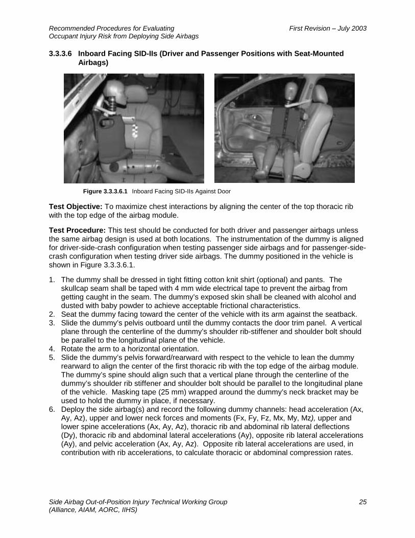
3.3.3.6 Inboard Facing SID-IIs (Driver and Passenger Positions with Seat-Mounted Airbags)
Figure 3.3.3.6.1 Inboard Facing SID-IIs Against Door
Test Objective: To maximize chest interactions by aligning the center of the top thoracic rib with the top edge of the airbag module.
Test Procedure: This test should be conducted for both driver and passenger airbags unless the same airbag design is used at both locations. The instrumentation of the dummy is aligned for driver-side-crash configuration when testing passenger side airbags and for passenger-side-crash configuration when testing driver side airbags. The dummy positioned in the vehicle is shown in Figure 3.3.3.6.1.
1. The dummy shall be dressed in tight fitting cotton knit shirt (optional) and pants. The skullcap seam shall be taped with 4 mm wide electrical tape to prevent the airbag from getting caught in the seam. The dummy’s exposed skin shall be cleaned with alcohol and dusted with baby powder to achieve acceptable frictional characteristics.
2. Seat the dummy facing toward the center of the vehicle with its arm against the seatback. 3. Slide the dummy’s pelvis outboard until the dummy contacts the door trim panel. A vertical
plane through the centerline of the dummy’s shoulder rib-stiffener and shoulder bolt should be parallel to the longitudinal plane of the vehicle.
4. Rotate the arm to a horizontal orientation. 5. Slide the dummy’s pelvis forward/rearward with respect to the vehicle to lean the dummy
rearward to align the center of the first thoracic rib with the top edge of the airbag module. The dummy’s spine should align such that a vertical plane through the centerline of the dummy’s shoulder rib stiffener and shoulder bolt should be parallel to the longitudinal plane of the vehicle. Masking tape (25 mm) wrapped around the dummy’s neck bracket may be used to hold the dummy in place, if necessary.
6. Deploy the side airbag(s) and record the following dummy channels: head acceleration (Ax, Ay, Az), upper and lower neck forces and moments (Fx, Fy, Fz, Mx, My, Mz), upper and lower spine accelerations (Ax, Ay, Az), thoracic rib and abdominal rib lateral deflections (Dy), thoracic rib and abdominal lateral accelerations (Ay), opposite rib lateral accelerations (Ay), and pelvic acceleration (Ax, Ay, Az). Opposite rib lateral accelerations are used, in contribution with rib accelerations, to calculate thoracic or abdominal compression rates.
Recommended Procedures for Evaluating First Revision – July 2003 Occupant Injury Risk from Deploying Side Airbags
Side Airbag Out-of-Position Injury Technical Working Group 26 (Alliance, AIAM, AORC, IIHS)
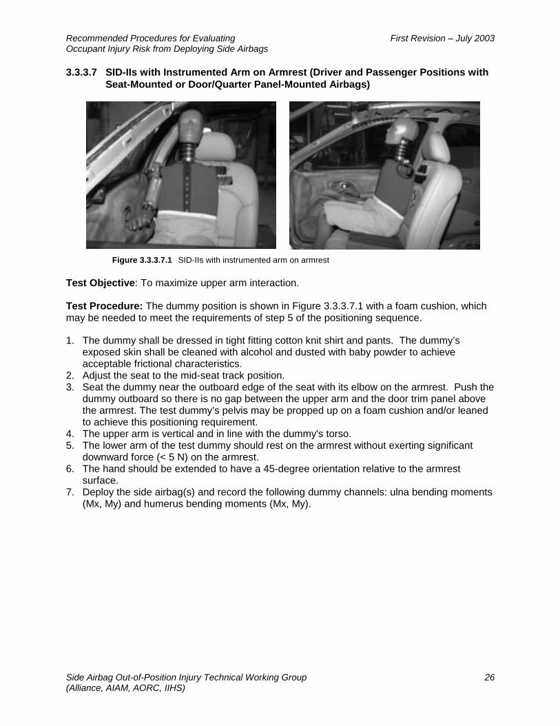
3.3.3.7 SID-IIs with Instrumented Arm on Armrest (Driver and Passenger Positions with Seat-Mounted or Door/Quarter Panel-Mounted Airbags)
Figure 3.3.3.7.1 SID-IIs with instrumented arm on armrest
Test Objective: To maximize upper arm interaction.
Test Procedure: The dummy position is shown in Figure 3.3.3.7.1 with a foam cushion, which may be needed to meet the requirements of step 5 of the positioning sequence.
1. The dummy shall be dressed in tight fitting cotton knit shirt and pants. The dummy’s exposed skin shall be cleaned with alcohol and dusted with baby powder to achieve acceptable frictional characteristics.
2. Adjust the seat to the mid-seat track position. 3. Seat the dummy near the outboard edge of the seat with its elbow on the armrest. Push the
dummy outboard so there is no gap between the upper arm and the door trim panel above the armrest. The test dummy’s pelvis may be propped up on a foam cushion and/or leaned to achieve this positioning requirement.
4. The upper arm is vertical and in line with the dummy's torso. 5. The lower arm of the test dummy should rest on the armrest without exerting significant
downward force (< 5 N) on the armrest. 6. The hand should be extended to have a 45-degree orientation relative to the armrest
surface. 7. Deploy the side airbag(s) and record the following dummy channels: ulna bending moments
(Mx, My) and humerus bending moments (Mx, My).

Recommended Procedures for Evaluating First Revision – July 2003 Occupant Injury Risk from Deploying Side Airbags
Side Airbag Out-of-Position Injury Technical Working Group 27 (Alliance, AIAM, AORC, IIHS)
3.3.4 Tests for Door/Quarter Panel-Mounted Airbags
3.3.4.1 Outboard Facing Hybrid III 3-Year-Old Child Dummy (Passenger Positions with Door/Quarter Panel-Mounted Airbags)
Figure 3.3.4.1.1 Outboard Facing Hybrid III 3-Year-Old Child Dummy Leaning Against Seat
and Door Trim Panel Test Objective: To maximize chest interaction by aligning the dummy’s sternum with the vertical centerline of the side airbag module.
Test Procedure: The dummy positioned in the vehicle is shown in Figure 3.3.4.1.1.
1. The dummy shall be dressed in tight fitting cotton knit shirt and pants. The skullcap seam shall be taped with 4 mm wide electrical tape to prevent the airbag from getting caught in the seam. The dummy’s head skin shall be cleaned with alcohol and dusted with baby powder to achieve acceptable frictional characteristics.
2. Place the dummy on the seat in a kneeling position facing out the side window with the rearmost knee in the seat bight. The dummy’s arms and hands should be hanging against the sides of the torso
3. Holding the dummy in a vertically upright position, adjust the seat track position to align the vertical centerline of the sternum with the vertical centerline of the airbag module. Geometric limits of the module may be defined through a blank deployment or obtained from the manufacturer. The seat back, in conjunction with the arm position, may be used to stabilize the dummy.
4. Keeping the head in its neutral orientation (i.e., head should not be forced into flexion or extension), lean the dummy outboard until the chest contacts the airbag module in the door trim panel.
5. Move the dummy’s knees inboard/outboard to align the top of the upper rib with the top edge of the airbag module as defined by the manufacturer. . It may be necessary to roll down the window to minimize the clearance between the chest and airbag module.
6. Deploy the side airbag(s) and record the following dummy channels: head acceleration (Ax, Ay, Az), upper and lower neck forces and moments (Fx, Fy, Fz, Mx, My, Mz), chest acceleration (Ax, Ay, Az), mid-sternum deflection (Dx), upper and lower sternum accelerations (Ax) and upper and lower spine accelerations (Ax, Ay, Az).

Recommended Procedures for Evaluating First Revision – July 2003 Occupant Injury Risk from Deploying Side Airbags
Side Airbag Out-of-Position Injury Technical Working Group 28 (Alliance, AIAM, AORC, IIHS)
3.3.4.2 Inboard Facing Hybrid III 3-Year-Old Child Dummy (Passenger Positions with Door/Quarter Panel-Mounted Airbags)
Figure 3.3.4.2.1 Inboard Facing Hybrid III 3-Year-Old Child Dummy Leaning Against Door
or Window Glazing Test Objective: To maximize head and neck interactions.
Test Procedure: The dummy positioned in the vehicle is shown in Figure 3.3.4.2.1.
1. This test should be conducted with the Hybrid III 3 year old. However, in vehicles where location of the airbag module precludes alignment of the head neck junction with the top edge of the airbag module, the use of Hybrid III 6 year old is recommended
2. The dummy shall be dressed in tight fitting cotton knit shirt and pants. The skullcap seam shall be taped with 4 mm wide electrical tape to prevent the airbag from getting caught in the seam. The dummy’s head skin shall be cleaned with alcohol and dusted with baby powder to achieve acceptable frictional characteristics.
3. With the dummy’s arms hanging along its sides, seat the dummy on the seat facing inboard with its legs extended.
4. Lean the dummy to the rear of the vehicle until its arm contacts the seat back. 5. Adjust the seat track position to align the dummy’s vertical centerline of the spine box with
the vertical centerline of the airbag module. Geometric limits of the module may be defined through a blank deployment or obtained from the manufacturer.
6. Keeping the head in its neutral orientation (i.e., head should not be forced into flexion or extension), lean the dummy back until its shoulders or head contact the door trim panel.
7. While maintaining the alignment of the dummy, slide the pelvis inboard/outboard until the head/neck junction (i.e., lower edge of the skin at the base of the head) is as aligned with the top edge of the airbag module. Seat height adjustments, if available, may be used to assist in final placement of the dummy. If this is not sufficient see step 1.
8. The dummy’s upper arms are parallel with its torso and lower arms are bent forward so the fingertips just touch the seat cushion.
9. Deploy the side airbag(s) and record the following dummy channels: head acceleration (Ax, Ay, Az) and upper and lower neck forces and moments (Fx, Fy, Fz, Mx, My, Mz).

Recommended Procedures for Evaluating First Revision – July 2003 Occupant Injury Risk from Deploying Side Airbags
Side Airbag Out-of-Position Injury Technical Working Group 29 (Alliance, AIAM, AORC, IIHS)
3.3.4.3 Hybrid III 3-Year-Old Child Dummy Lying on Seat with Head on Armrest (Passenger Positions with Door/Quarter Panel-Mounted Airbags)
Figure 3.3.4.3.1 Hybrid III 3-Year-Old Child Dummy Lying Across Seat with Head
on Door Trim Panel Test Objective: To maximize the head and neck interaction by aligning the head with the center of the airbag module.
Test Procedure: A foam wedge, which is wide enough to support the dummy across the full width of its back (approximately 300 mm), is used to support the dummy’s weight. The remaining dimensions of the wedge should be chosen to allow the dummy’s head to touch the armrest without applying a significant downward force. The foam’s density should be 40-80 g/l. A typical foam material is expanded polypropylene (EPP). The dummy’s position in the vehicle is shown in Figure 3.3.4.3.1. Specific positioning instructions are as follows:
1. The dummy shall be dressed in tight fitting cotton knit shirt and pants. The skullcap seam shall be taped with 4 mm wide electrical tape to prevent the airbag from getting caught in the seam. The dummy’s head skin shall be cleaned with alcohol and dusted with baby powder to achieve acceptable frictional characteristics.
2. Place the dummy on the seat lying on its back with its arms at its sides so that its rearmost arm contacts the seatback.
3. Adjust the seat track position to align the horizontal centerline of the dummy’s head as close as possible to the vertical centerline of the airbag module. Geometric limits of the module may be defined through a blank deployment or obtained from the manufacturer.
3. Slide the dummy outboard until the head just contacts the module (armrest contact must be maintained). Support the dummy’s back with a wedge-shaped foam block so that the head remains in a neutral position (i.e., head should not be forced into flexion or extension) and does not exert a significant downward force (< 5N) on the armrest.
4. Adjust the dummy’s arm closest to the front edge of the seat so that it is parallel to the torso and rests on the foam block with the fingertips just touching the seat cushion.
5. Adjust the rearmost upper arm to an orientation 45 degrees forward of the torso centerline and the forearm on the same side to an orientation 90 degrees to the upper arm.
6. Deploy the side airbag(s) and record the following dummy channels: head acceleration (Ax, Ay, Az) and upper and lower neck forces and moments (Fx, Fy, Fz, Mx, My, Mz).

Recommended Procedures for Evaluating First Revision – July 2003 Occupant Injury Risk from Deploying Side Airbags
Side Airbag Out-of-Position Injury Technical Working Group 30 (Alliance, AIAM, AORC, IIHS)
3.3.4.4 Hybrid III 3-Year-Old Child Dummy Lying on Seat (Passenger Positions with Door/Quarter Panel-Mounted Airbags)
Figure 3.3.4.4.1 Hybrid III 3-Year-Old Child Dummy Lying Across Seat
Test Objective: To maximize the head and neck interaction by aligning the head with the vertical centerline of the door/quarter panel-mounted airbag module.
Test Procedure: The dummy positioned in the vehicle is shown in Figure 3.3.4.4.1. Specific positioning instructions are as follows:
1. The dummy shall be dressed in tight fitting cotton knit shirt and pants. The skullcap seam shall be taped with 4 mm wide electrical tape to prevent the airbag from getting caught in the seam. The dummy’s head skin shall be cleaned with alcohol and dusted with baby powder to achieve acceptable frictional characteristics.
2. Place the dummy on the seat lying on its back with its arms at its sides so that its rearmost arm contacts the seatback.
4. Adjust the seat track position to align the center of the dummy’s head as close as possible to the vertical centerline of the airbag module. Geometric limits of the module may be defined through a blank deployment or obtained from the manufacturer.
3. Adjust seat height, if adjustable, to align the instrumentation plane of the dummy’s head as near as possible to the horizontal center of the airbag module.
4. Slide the dummy outboard until the head just contacts the airbag module. 5. If necessary, stabilize the dummy by placing a block of lightweight foam under the
dummy’s legs. 6. Deploy the side airbag(s) and record the following dummy channels: head acceleration (Ax,
Ay, Az) and upper and lower neck forces and moments (Fx, Fy, Fz, Mx, My, Mz).
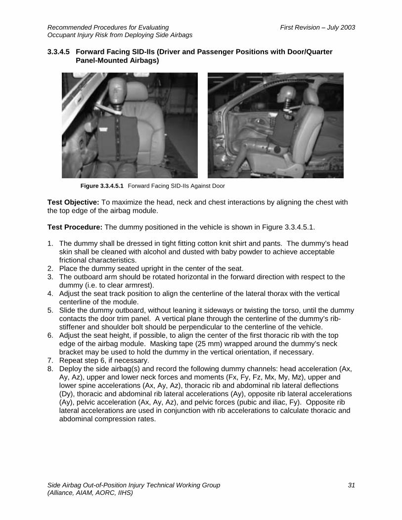
Recommended Procedures for Evaluating First Revision – July 2003 Occupant Injury Risk from Deploying Side Airbags
Side Airbag Out-of-Position Injury Technical Working Group 31 (Alliance, AIAM, AORC, IIHS)
3.3.4.5 Forward Facing SID-IIs (Driver and Passenger Positions with Door/Quarter Panel-Mounted Airbags)
Figure 3.3.4.5.1 Forward Facing SID-IIs Against Door
Test Objective: To maximize the head, neck and chest interactions by aligning the chest with the top edge of the airbag module.
Test Procedure: The dummy positioned in the vehicle is shown in Figure 3.3.4.5.1.
1. The dummy shall be dressed in tight fitting cotton knit shirt and pants. The dummy’s head skin shall be cleaned with alcohol and dusted with baby powder to achieve acceptable frictional characteristics.
2. Place the dummy seated upright in the center of the seat. 3. The outboard arm should be rotated horizontal in the forward direction with respect to the
dummy (i.e. to clear armrest). 4. Adjust the seat track position to align the centerline of the lateral thorax with the vertical
centerline of the module. 5. Slide the dummy outboard, without leaning it sideways or twisting the torso, until the dummy
contacts the door trim panel. A vertical plane through the centerline of the dummy’s rib-stiffener and shoulder bolt should be perpendicular to the centerline of the vehicle.
6. Adjust the seat height, if possible, to align the center of the first thoracic rib with the top edge of the airbag module. Masking tape (25 mm) wrapped around the dummy’s neck bracket may be used to hold the dummy in the vertical orientation, if necessary.
7. Repeat step 6, if necessary. 8. Deploy the side airbag(s) and record the following dummy channels: head acceleration (Ax,
Ay, Az), upper and lower neck forces and moments (Fx, Fy, Fz, Mx, My, Mz), upper and lower spine accelerations (Ax, Ay, Az), thoracic rib and abdominal rib lateral deflections (Dy), thoracic and abdominal rib lateral accelerations (Ay), opposite rib lateral accelerations (Ay), pelvic acceleration (Ax, Ay, Az), and pelvic forces (pubic and iliac, Fy). Opposite rib lateral accelerations are used in conjunction with rib accelerations to calculate thoracic and abdominal compression rates.

Recommended Procedures for Evaluating First Revision – July 2003 Occupant Injury Risk from Deploying Side Airbags
Side Airbag Out-of-Position Injury Technical Working Group 32 (Alliance, AIAM, AORC, IIHS)
3.3.5 Tests for Roof-Rail-Mounted Airbags
3.3.5.1 Inboard Facing Hybrid III 6-Year-Old Child Dummy on Booster Block (Passenger Positions with Roof-Rail-Mounted Airbags)
Figure 3.3.5.1.1 Inboard Facing Hybrid III 6-Year-Old Child Dummy on Booster Block
Test Objective: To maximize the head/neck interaction by positioning the head in the path of the deploying airbag.
Test Procedure: For this test the seat is adjusted to its highest position. The booster foam block dimensions are 300 mm deep by 450 mm wide by 75 mm thick. The foam has a density of 40-80 g/l. A typical foam material is expanded polypropylene (EPP). Center the foam block on seat cushion so that it contacts the seat back bolsters. Do not tape or otherwise attach the booster to the seat. The dummy positioned in the vehicle is shown in Figure 3.3.5.1.1.
1. The dummy shall be dressed in tight fitting cotton knit shirt and pants. The skullcap seam shall be taped with 4mm electrical tape to prevent the airbag from getting caught in the seam. The dummy’s head skin shall be cleaned with alcohol and dusted with baby powder to achieve acceptable frictional characteristics.
2. Place the dummy with its arms hanging at its sides on the foam block facing inboard with its legs extended.
3. Adjust the seat track position forward to minimize the vertical distance between the dummy’s head and the roof-rail module and to maximize the cushion to head interaction.
4. Keeping the head in its neutral orientation (i.e., head should not be forced into flexion or extension), slide the dummy’s pelvis outboard until the dummy’s back contacts the door trim panel or armrest and the center of gravity of the head is centered in the deployment trajectory of the airbag. It may be necessary to tilt the dummy outboard in order to achieve proper alignment of the head. A vertical plane through the centerline of the dummy’s shoulder bolts should be parallel to the vehicle centerline.
5. Bend the dummy’s arms at the elbow until the fingers just touch the booster seat. 6. Deploy the side airbag(s) and record the following dummy channels: head acceleration (Ax,
Ay, Az) and upper and lower neck forces and moments (Fx, Fy, Fz, Mx, My, Mz).

Recommended Procedures for Evaluating First Revision – July 2003 Occupant Injury Risk from Deploying Side Airbags
Side Airbag Out-of-Position Injury Technical Working Group 33 (Alliance, AIAM, AORC, IIHS)
3.3.5.2 Forward Facing SID-IIs on Raised Seat (Driver and Passenger Positions with Roof-Rail-Mounted Airbags)
Figure 3.3.5.2.1 Forward Facing SID-IIs Aligned for Test of Roof-Rail-Mounted Airbag
Test Objective: To maximize the head/neck interaction by positioning the head in the path of the deploying airbag.
Test Procedure: For this test the seat is adjusted to its highest position. The dummy positioned in the vehicle is shown in Figure 3.3.5.2.1
1. The dummy shall be dressed in tight fitting cotton knit shirt and pants. The dummy’s head skin shall be cleaned with alcohol and dusted with baby powder to achieve acceptable frictional characteristics.
2. Place the dummy seated upright in the center of the seat. 3. The outboard arm should be rotated horizontal in the forward direction with respect to the
dummy (i.e. to clear armrest). 4. Adjust the seat track position forward to minimize the vertical distance between the
dummy’s head and the roof-rail module and to maximize the cushion to head interaction. 5. Move the dummy outboard until the dummy contacts the door trim panel. The dummy may
be leaned outboard to ensure that the deployment trajectory of the airbag will intersect with the centerline of the top of the head (pelvis may need to be adjusted inboard to achieve this position). Masking tape (25mm) wrapped around the dummy’s neck bracket may be used to hold the dummy in the test orientation if necessary.
6. Deploy the side airbag(s) and record the following dummy channels: head acceleration (Ax, Ay, Az) and upper and lower neck forces and moments (Fx, Fy, Fz, Mx, My, Mz).
7. If driver and right-front passenger side airbag systems are identical, then only one position need be tested.
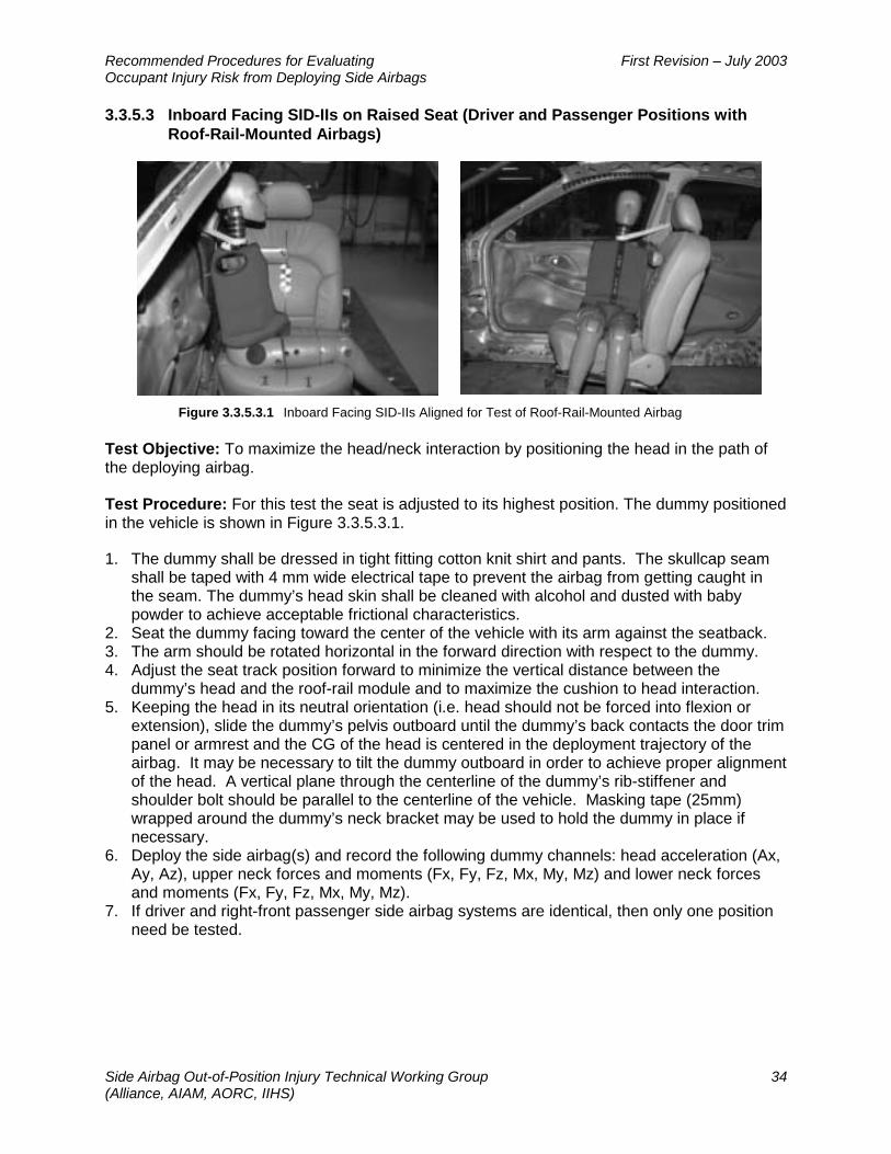
Recommended Procedures for Evaluating First Revision – July 2003 Occupant Injury Risk from Deploying Side Airbags
Side Airbag Out-of-Position Injury Technical Working Group 34 (Alliance, AIAM, AORC, IIHS)
3.3.5.3 Inboard Facing SID-IIs on Raised Seat (Driver and Passenger Positions with Roof-Rail-Mounted Airbags)
Figure 3.3.5.3.1 Inboard Facing SID-IIs Aligned for Test of Roof-Rail-Mounted Airbag
Test Objective: To maximize the head/neck interaction by positioning the head in the path of the deploying airbag.
Test Procedure: For this test the seat is adjusted to its highest position. The dummy positioned in the vehicle is shown in Figure 3.3.5.3.1.
1. The dummy shall be dressed in tight fitting cotton knit shirt and pants. The skullcap seam shall be taped with 4 mm wide electrical tape to prevent the airbag from getting caught in the seam. The dummy’s head skin shall be cleaned with alcohol and dusted with baby powder to achieve acceptable frictional characteristics.
2. Seat the dummy facing toward the center of the vehicle with its arm against the seatback. 3. The arm should be rotated horizontal in the forward direction with respect to the dummy. 4. Adjust the seat track position forward to minimize the vertical distance between the
dummy’s head and the roof-rail module and to maximize the cushion to head interaction. 5. Keeping the head in its neutral orientation (i.e. head should not be forced into flexion or
extension), slide the dummy’s pelvis outboard until the dummy’s back contacts the door trim panel or armrest and the CG of the head is centered in the deployment trajectory of the airbag. It may be necessary to tilt the dummy outboard in order to achieve proper alignment of the head. A vertical plane through the centerline of the dummy’s rib-stiffener and shoulder bolt should be parallel to the centerline of the vehicle. Masking tape (25mm) wrapped around the dummy’s neck bracket may be used to hold the dummy in place if necessary.
6. Deploy the side airbag(s) and record the following dummy channels: head acceleration (Ax, Ay, Az), upper neck forces and moments (Fx, Fy, Fz, Mx, My, Mz) and lower neck forces and moments (Fx, Fy, Fz, Mx, My, Mz).
7. If driver and right-front passenger side airbag systems are identical, then only one position need be tested.

Recommended Procedures for Evaluating First Revision – July 2003 Occupant Injury Risk from Deploying Side Airbags
Side Airbag Out-of-Position Injury Technical Working Group 35 (Alliance, AIAM, AORC, IIHS)
References
American Automobile Manufacturers Association. 1998. Comment to the National Highway Traffic Safety Administration on Advanced Technology Airbags (AAMA S98-13) — Attachment C: Proposal for Dummy Response Limits for FMVSS 208 Compliance Testing. Docket No. NHTSA 98-4405, Notice 1; DMS Document No. NHTSA-1998-4405-79, Dec. 17, 1998. Washington, DC.
Alliance of Automobile Manufacturers. 1999. Comment to the National Highway Traffic Safety Administration on Supplemental Notice of Proposed Rulemaking, FMVSS 208, Occupant Crash Protection — Annex 2: Dummy Response Limits for FMVSS 208 Compliance Testing. Docket No. NHTSA 99-6407, Notice 1; DMS Document No. NHTSA-1999-6407-40, Dec. 23, 1999. Washington, DC.
Begeman, P.C.; Pratima K.; and Prasad, P. 1999. Bending strength of the human cadaveric forearm due to lateral loads (SAE 99SC24). Proceedings of the 43rd Stapp Car Crash Conference (P-350), 343-50. Warrendale, PA: Society of Automotive Engineers.
Daniel, R.P.; Irwin, A.; Athey, J.; Balser, J.; Eichbrecht, P.; Hultman, R.W. et al. 1995. Technical specifications of the SID IIs dummy (SAE 952735). Proceedings of the 39th Stapp Car Crash Conference (P-229), 359-88. Warrendale, PA: Society of Automotive Engineers.
Irwin, A.L. and Mertz, H.J. 1997. Biomechanical bases for the CRABI and Hybrid III child dummies (SAE 973317). Proceeding of the 41st Stapp Car Crash Conference (P-315), 1-12. Warrendale, PA: Society of Automotive Engineers.
Kirkish, S.L.; Begeman, P.C.; and Paravasthu, N.S. 1996. Proposed provisional reference values for the humerus for evaluation of injury potential (SAE 962416). Proceedings of the 40th Stapp Car Crash Conference (P-305), 75-84. Warrendale, PA: Society of Automotive Engineers.
Mertz, H.J. 1984. A procedure for normalizing impact response data. SAE Technical Paper Series 840884. Warrendale, PA: Society of Automotive Engineers.
Mertz, H.J. 1993. Anthropomorphic test devices. Accidental Injury: Biomechanics and Prevention (eds. A.M. Nahum and J.W. Melvin), 66-84. New York, NY: Springer-Verlag.
Mertz, H.J.; Driscoll, G.D.; Lenox, J.B.; Nyquist, G.W.; and Weber, D.A. 1982. Responses of animals exposed to various passenger inflatable restraint system concepts for a variety of collision severities and animal positions. Proceedings of the 9th International Technical Conference on Experimental Safety Vehicles, 352-68. Washington, DC: National Highway Traffic Safety Administration.
Mertz, H.J.; Prasad, P.; and Irwin, A.L. 1997. Injury risk curves for children and adults in frontal and rear collisions (SAE 973318). Proceeding of the 41st Stapp Car Crash Conference (P-315), 13-30. Warrendale, PA: Society of Automotive Engineers.
Mertz, H.J. and Weber, D.A. 1982. Interpretations of the impact responses of a three-year-old child dummy relative to child injury potential. Proceedings of the 9th International Technical Conference on Experimental Safety Vehicles, 368-76. Washington, DC: National Highway Traffic Safety Administration. (Also published as SAE 826048)

Recommended Procedures for Evaluating First Revision – July 2003 Occupant Injury Risk from Deploying Side Airbags
Side Airbag Out-of-Position Injury Technical Working Group 36 (Alliance, AIAM, AORC, IIHS)
Pintar, F.A.; Yoganandan, N.; and Eppinger, R.H. 1998. Response and tolerance of the human forearm to impact loading (SAE 983149). Proceedings of the 42nd Stapp Car Crash Conference (P-337), 65-76. Warrendale, PA: Society of Automotive Engineers.
Prasad, P. and Daniel, R.P.A. 1984. Biomechanical analysis of head, neck, and torso injuries to child surrogates due to sudden torso acceleration (SAE 841656). Proceedings of the 28th Stapp Car Crash Conference (P-152), 25-41. Warrendale, PA: Society of Automotive Engineers.
Prasad, P.; Kim, A.; and Weerappuli, D. 1997. Biofidelity of anthropomorphic test devices for rear impact (SAE 973342). Proceedings of the 41st Stapp Car Crash Conference (P-315), 387-415. Warrendale, PA: Society of Automotive Engineers.
Guidelines for Evaluating Out-of-Position Vehicle Occupant Interactions with Deploying Airbags. SAE Information Report J 1980. Issued November 26, 1990, revised January 2001.
ISO/TR 10982:1998 Road vehicles – Test procedure for evaluating out-of-position vehicle occupant interactions with deploying airbags.
ISO/TR 14933:2000 Road vehicles – Test procedures for evaluating occupant interactions with deploying side impact airbags.
Anthropomorphic Dummies for Crash and Escape System Testing, AGARD – AR330, NATO, July, 1996.
Society of Automotive Engineers, Engineering Aid 31, Hybrid III 3-Year-Old Child Dummy, 2000.
Society of Automotive Engineers, Engineering Aid 29, Hybrid III 6-Year-Old Child Dummy, 1998.
Society of Automotive Engineers, Engineering Aid 25, Hybrid III Small Female Dummy, 1994.
Society of Automotive Engineers, J211, Instrumentation for Impact Test - Part 1 - Electronic Instrumentation, March, 1995.
Society of Automotive Engineers, J2189, Guidelines for evaluating child restraint system interactions with deploying airbags. Issued March 19, 1993; revised December 2000.
ISO/TR 14645:1998. Road vehicles – Test procedures for evaluating child restraint system interactions with deploying airbags.
Recommended Procedures for Evaluating First Revision – July 2003 Occupant Injury Risk from Deploying Side Airbags
Side Airbag Out-of-Position Injury Technical Working Group A-1 (Alliance, AIAM, AORC, IIHS)
Appendix A – Dummy Injury Research Values
As stated in the body of the report, the Injury Research Values represent important indicators of potential injury, but the engineering and scientific community does not yet have a sufficient biomechanical and other scientific basis to know that the published values correctly predict injury risks from deploying side airbags. In some cases, additional biomechanical research is needed to understand adequately the mechanisms that cause injury to particular body regions (e.g., the lower neck, abdominal and pelvic injuries) and the mechanisms of injury associated with side airbags (e.g., whether spinal acceleration is a predictor of side airbag injury risk). In other cases, additional work is needed to correlate measurable dummy responses to injury mechanisms that have established risk curves. Still more work is needed to provide adequate test experience with some of these measures to gain confidence in their accuracy.
As this research progresses, the engineering and scientific community will have a basis on which to establish Injury Reference Values for some or all of these indicators. The TWG recommends that it be reconvened periodically to review the continuing scientific status of its recommended procedures, including these Injury Research Values. It should be emphasized that a larger body of scientific data is needed to confirm what the correct Injury Reference Value should be, not simply to verify or validate the value published here as an Injury Research Value. When a given injury measure is sufficiently well understood to become an Injury Reference Value, it may be the same value published here as a research value, or it may be a higher or lower value.
At this time, the TWG recommends that manufacturers and suppliers consider the Injury Research Values when designing future side airbag systems and accommodate them in those designs where feasible. However, the TWG agreed that a future side airbag designed according to the Injury Reference Values need not be discarded solely to accommodate an Injury Research Value.
Table A1, below, is a list of the dummy responses that are recommended as Injury Research Values. The following sections explain how the Injury Research Values were derived and the level of scientific understanding associated with the published values.
A.1 Neck Injuries
A.1.1 Upper Neck Load Cell
Reported test experience with the recommended procedures led the TWG to recommend that lateral bending and twisting of the neck should be monitored. There was relatively little experience measuring these neck moments on the dummy, and the Injury Research Values were only recently proposed based on the judgment of biomechanics experts in the TWG. The twist moment values were set at the same level as the extension values, the neck’s weakest bending mode, because the cervical vertebrae can easily be separated by twisting of the head. The lateral bending moment values were set midway between the extension and flexion values because the amount of muscle and connective tissue that resists lateral bending is greater than the amount that resists extension bending, but not greater than the amount that resists flexion, the neck’s strongest bending mode.
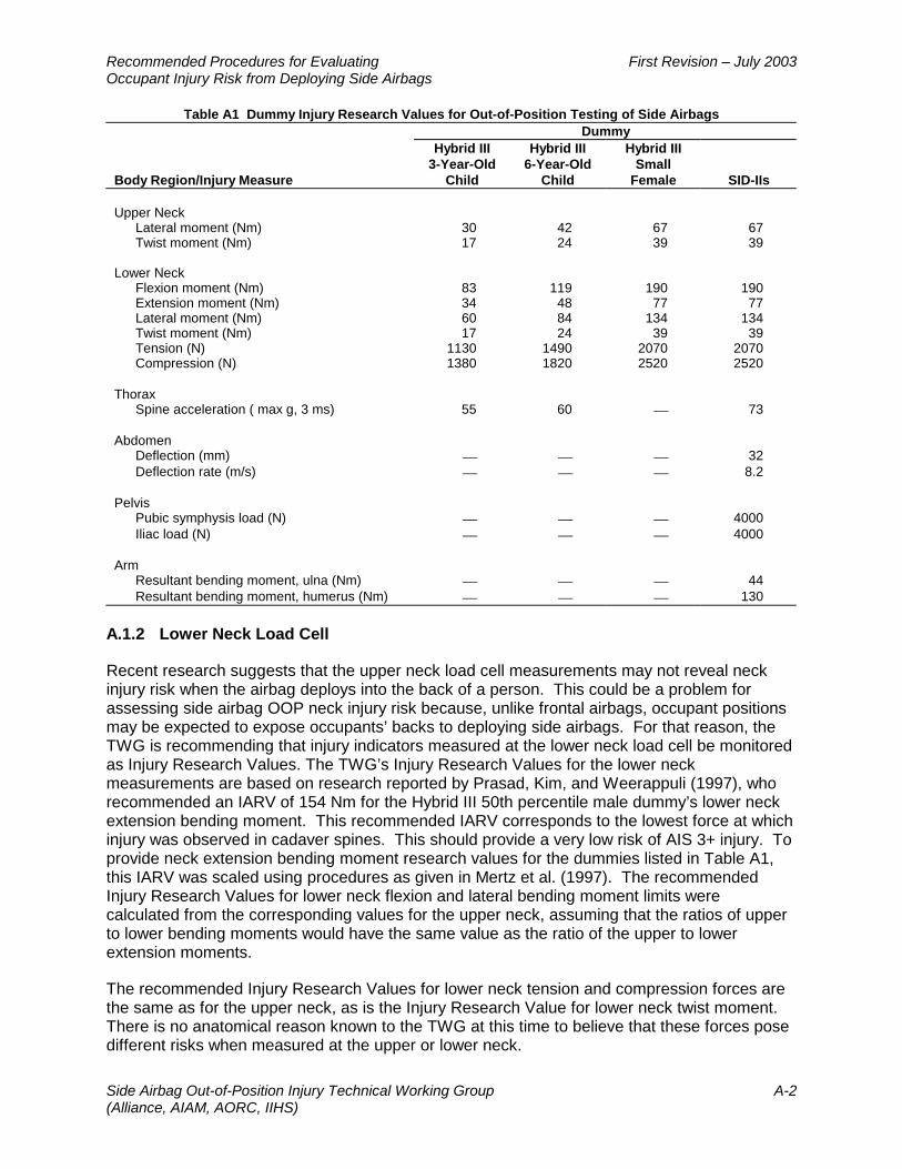
Recommended Procedures for Evaluating First Revision – July 2003 Occupant Injury Risk from Deploying Side Airbags
Side Airbag Out-of-Position Injury Technical Working Group A-2 (Alliance, AIAM, AORC, IIHS)
Table A1 Dummy Injury Research Values for Out-of-Position Testing of Side Airbags Dummy
Body Region/Injury Measure
Hybrid III 3-Year-Old
Child
Hybrid III 6-Year-Old
Child
Hybrid III Small
Female SID-IIs Upper Neck
Lateral moment (Nm) 30 42 67 67 Twist moment (Nm) 17 24 39 39
Lower Neck Flexion moment (Nm) 83 119 190 190 Extension moment (Nm) 34 48 77 77 Lateral moment (Nm) 60 84 134 134 Twist moment (Nm) 17 24 39 39 Tension (N) 1130 1490 2070 2070 Compression (N) 1380 1820 2520 2520
Thorax
Spine acceleration ( max g, 3 ms) 55 60 73
Abdomen Deflection (mm) 32 Deflection rate (m/s) 8.2
Pelvis Pubic symphysis load (N) 4000 Iliac load (N) 4000
Arm Resultant bending moment, ulna (Nm) 44 Resultant bending moment, humerus (Nm) 130
A.1.2 Lower Neck Load Cell
Recent research suggests that the upper neck load cell measurements may not reveal neck injury risk when the airbag deploys into the back of a person. This could be a problem for assessing side airbag OOP neck injury risk because, unlike frontal airbags, occupant positions may be expected to expose occupants’ backs to deploying side airbags. For that reason, the TWG is recommending that injury indicators measured at the lower neck load cell be monitored as Injury Research Values. The TWG’s Injury Research Values for the lower neck measurements are based on research reported by Prasad, Kim, and Weerappuli (1997), who recommended an IARV of 154 Nm for the Hybrid III 50th percentile male dummy’s lower neck extension bending moment. This recommended IARV corresponds to the lowest force at which injury was observed in cadaver spines. This should provide a very low risk of AIS 3+ injury. To provide neck extension bending moment research values for the dummies listed in Table A1, this IARV was scaled using procedures as given in Mertz et al. (1997). The recommended Injury Research Values for lower neck flexion and lateral bending moment limits were calculated from the corresponding values for the upper neck, assuming that the ratios of upper to lower bending moments would have the same value as the ratio of the upper to lower extension moments.
The recommended Injury Research Values for lower neck tension and compression forces are the same as for the upper neck, as is the Injury Research Value for lower neck twist moment. There is no anatomical reason known to the TWG at this time to believe that these forces pose different risks when measured at the upper or lower neck.

Recommended Procedures for Evaluating First Revision – July 2003 Occupant Injury Risk from Deploying Side Airbags
Side Airbag Out-of-Position Injury Technical Working Group A-3 (Alliance, AIAM, AORC, IIHS)
A.2 Thoracic Injuries
The TWG recommends that spine acceleration be included as an Injury Research Value in OOP testing of side airbags. The TWG expressed doubt that spine acceleration could indicate thoracic injury likelihood in the absence of excessive compression or compression rate (which are included as Injury Reference Values, Table 2). However, it was noted that this measure is the standard measure included in NHTSA evaluations of thoracic injury. The Injury Research Values for spine acceleration included in Table A1 are scaled from the value specified by Federal Motor Vehicle Safety Standard 208 for the 50th percentile adult male (a maximum of 60 g maintained for 3 ms).
A.3 Abdominal and Pelvic Injuries
Among the dummies recommended for OOP testing of side airbags, only the SID-IIs is instrumented to measure abdominal and pelvic responses to input. The TWG recommends monitoring dummy response for both abdominal compression and compression rate for the SID-IIs. The abdominal compression Injury Research Value is scaled from an IARV of 39 mm for the 50th percentile male dummy, BioSID (NATO, 1996). In the absence of any IARV for abdominal compression rate, the TWG’s biomechanics experts recommended that the Injury Reference Value for thoracic compression rate be used as an Injury Research Value for abdominal compression rate. Injury Research Values are also recommended for forces on the pubic symphysis and the iliac crest by scaling from IARVs which have been suggested for the BioSID. These IARVs reflect the force levels at which fractures of these structures are expected. It should be noted that no side airbags are expected to approach these force levels for the SID-IIs, but the TWG nevertheless concluded that these variables should be monitored.
A.4 Arm Injuries
The TWG recommends Injury Research Values for fracture of both the ulna and humerus of the SID-IIs. The Injury Research Value recommended for bending moment of the ulna was derived from the work of Begeman et al. (1999) and Pintar et al. (1998). Begeman et al. reported that the ulnae (forearms) in a sample of adult cadavers failed at an average moment of 89 Nm, while Pintar et al. found an average failure moment of 94 Nm. The TWG agreed that these data supported an IARV of 90 Nm for the 50th percentile male. This limit was scaled down to 44 Nm for members of the population sized similarly to the SID-IIs.
The 130 Nm Injury Research Value for the humerus (upper arm) was recommended by Kirkish et al (1996) for the SID-IIs with instrumented arm.
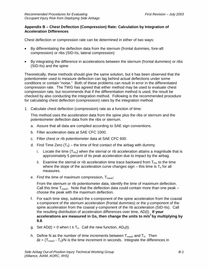
Recommended Procedures for Evaluating First Revision – July 2003 Occupant Injury Risk from Deploying Side Airbags
Side Airbag Out-of-Position Injury Technical Working Group B-1 (Alliance, AIAM, AORC, IIHS)
Appendix B – Chest Deflection (Compression) Rate: Calculation by Integration of Acceleration Differences
Chest deflection or compression rate can be determined in either of two ways:
• By differentiating the deflection data from the sternum (frontal dummies, fore-aft compression) or ribs (SID-IIs, lateral compression)
• By integrating the difference in accelerations between the sternum (frontal dummies) or ribs (SID-IIs) and the spine
Theoretically, these methods should give the same solution, but it has been observed that the potentiometer used to measure deflection can lag behind actual deflections under some conditions or contain “noise.” Both of these problems can result in error in the differentiated compression rate. The TWG has agreed that either method may be used to evaluate chest compression rate, but recommends that if the differentiation method is used, the result be checked by also conducting the integration method. Following is the recommended procedure for calculating chest deflection (compression) rates by the integration method.
1. Calculate chest deflection (compression) rate as a function of time:
This method uses the acceleration data from the spine plus the ribs or sternum and the potentiometer deflection data from the ribs or sternum.
a. Assure that all data are compiled according to SAE sign conventions.
b. Filter acceleration data at SAE CFC 1000.
c. Filter chest or rib potentiometer data at SAE CFC 600.
d. Find Time Zero (T0) – the time of first contact of the airbag with dummy.
i. Locate the time (T5%) when the sternal or rib acceleration attains a magnitude that is approximately 5 percent of its peak acceleration due to impact by the airbag.
ii. Examine the sternal or rib acceleration time trace backward from T5% to the time where the slope of the acceleration curve changes sign – this time is T0 for all measures.
e. Find the time of maximum compression, TmaxD:
From the sternum or rib potentiometer data, identify the time of maximum deflection. Call this time TmaxD. Note that the deflection data could contain more than one peak – choose the peak with the maximum deflection.
f. For each time step, subtract the x-component of the spine acceleration from the coaxial x-component of the sternum acceleration (frontal dummies) or the y-component of the spine acceleration from the coaxial y-component of the rib acceleration (SID-IIs). Call the resulting distribution of acceleration differences over time, AD(t). If your accelerations are measured in Gs, then change the units to m/s2 by multiplying by 9.8.
g. Set AD(t) = 0 when t ≤ T0. Call the new function, AD0(t).
h. Define N as the number of time increments between TmaxD and T0. Then ∆t = (TmaxD - T0)/N is the time increment in seconds. Integrate the differences in
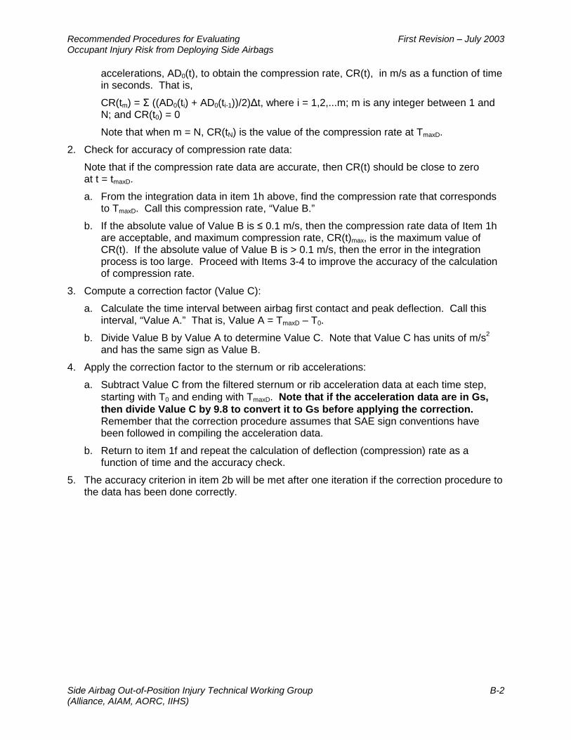
Recommended Procedures for Evaluating First Revision – July 2003 Occupant Injury Risk from Deploying Side Airbags
Side Airbag Out-of-Position Injury Technical Working Group B-2 (Alliance, AIAM, AORC, IIHS)
accelerations, AD0(t), to obtain the compression rate, CR(t), in m/s as a function of time in seconds. That is,
CR(tm) = Σ ((AD0(ti) + AD0(ti-1))/2)∆t, where i = 1,2,...m; m is any integer between 1 and N; and CR(t0) = 0
Note that when m = N, CR(tN) is the value of the compression rate at TmaxD.
2. Check for accuracy of compression rate data:
Note that if the compression rate data are accurate, then CR(t) should be close to zero at t = tmaxD.
a. From the integration data in item 1h above, find the compression rate that corresponds to TmaxD. Call this compression rate, “Value B.”
b. If the absolute value of Value B is ≤ 0.1 m/s, then the compression rate data of Item 1h are acceptable, and maximum compression rate, CR(t)max, is the maximum value of CR(t). If the absolute value of Value B is > 0.1 m/s, then the error in the integration process is too large. Proceed with Items 3-4 to improve the accuracy of the calculation of compression rate.
3. Compute a correction factor (Value C):
a. Calculate the time interval between airbag first contact and peak deflection. Call this interval, “Value A.” That is, Value A = TmaxD – T0.
b. Divide Value B by Value A to determine Value C. Note that Value C has units of m/s2
and has the same sign as Value B.
4. Apply the correction factor to the sternum or rib accelerations:
a. Subtract Value C from the filtered sternum or rib acceleration data at each time step, starting with T0 and ending with TmaxD. Note that if the acceleration data are in Gs, then divide Value C by 9.8 to convert it to Gs before applying the correction. Remember that the correction procedure assumes that SAE sign conventions have been followed in compiling the acceleration data.
b. Return to item 1f and repeat the calculation of deflection (compression) rate as a function of time and the accuracy check.
5. The accuracy criterion in item 2b will be met after one iteration if the correction procedure to the data has been done correctly.