Embed Size (px)
Citation preview


Recommendations forDesign and Analysis of EarthStructures using GeosyntheticReinforcements – EBGEO

Recommendations forDesign and Analysis of EarthStructures using GeosyntheticReinforcements – EBGEO
Translation of the
2nd German Edition
Published by
the German Geotechnical Society
(Deutsche Gesellschaft f�r Geotechnik e.V., DGGT)
DGGTDeutsche Gesellschaftfür Geotechnik e. V.German Geotechnical Society
Working Group 5.2 ,Analysis and Dimensioning of Soil Structures using Geosynthetic Reinforce-ments‘ Technical Group ,Synthetics in Geotechnical Engineering‘ of the German Geotechnical SocietyChairman: AOR Dipl.-Ing. Gerhard Br�uTechnische Universit�t M�nchenZentrum GeotechnikLehrstuhl und Pr�famt f�r Grundbau, Bodenmechanik,Felsmechanik und TunnelbauBaumbachstraße 781245 M�nchenGermany
Translator: Alan Johnson, Nordstemmen/Adensen, Germany
Cover photographs:Top left: Geotextile-encased sand columns on the M�hlenberger Loch project, Hamburg (photo:Huesker Synthetic GmbH); Top right: Steep embankment for heavy goods vehicle transport in Aalen,reinforced using geogrids (photo: Tensar International GmbH); Bottom left: Landslide rehabilitationusing geogrids along the B115 road near Altenmarkt in Austria (photo: TenCate GeosyntheticsDeutschland GmbH); Bottom right: Geogrids as base course reinforcement in redevelopment of aformer mining spoil tip along the A38 autobahn near Leipzig (photo: Naue GmbH & Co. KG)
Library of Congress Card No.:applied for
British Library Cataloguing-in-Publication DataA catalogue record for this book is available from the British Library.
Bibliographic information published by the Deutsche NationalbibliothekThe Deutsche Nationalbibliothek lists this publication in the Deutsche Nationalbibliografie; detailedbibliographic data are available on the Internet at <http://dnb.d-nb.de>.
� 2011 Wilhelm Ernst & Sohn,Verlag f�r Architektur und technische Wissenschaften GmbH & Co. KG, Rotherstr. 21, 10245 Berlin,Germany
All rights reserved (including those of translation into other languages). No part of this book may bereproduced in any form – by photoprinting, microfilm, or any other means – nor transmitted ortranslated into a machine language without written permission from the publishers. Registered names,trademarks, etc. used in this book, even when not specifically marked as such, are not to be consideredunprotected by law.
Coverdesign: Designpur, BerlinProduction Management: pp030 – Produktionsb�ro Heike Praetor, BerlinTypesetting: Manuela Treindl, F�rthPrinting and Binding: Strauss GmbH, Mçrlenbach
Printed in the Federal Republic of Germany.Printed on acid-free paper.
ISBN 978-3-433-02983-1Electronic version available. O-Book ISBN 978-3-433-60093-1

VRecommendations for Design and Analysis of Earth Structures using Geosynthetic Reinforcements (EBGEO). German Geotechnical Society.© 2011 Ernst & Sohn GmbH & Co. KG. Published by Ernst & Sohn GmbH & Co. KG.
German Geotechnical Society
Working Group 5.2Analysis and Dimensioning of Earth structures usingGeosynthetic ReinforcementsChairman: Dipl.-Ing. Bräu, MunichDeputy Chairman: Dipl.-Ing. Herold, Weimar
Members of the Working Group:
Dr.-Ing. Alexiew, GescherDr.-Ing. Bauer, OlchingDipl.-Ing. Blume, OverathDipl.-Geol. Blume, Bergisch-GladbachDipl.-Ing. Dollowski, BonnProf. Dr.-Ing. Göbel, DresdenDipl.-Ing. Hubal, Munich (formerly)Dipl.-Ing. Jas, AM Oostvoorne (formerly)Prof. Dr.-Ing. Kempfert, KasselProf. Dr.-Ing. Klapperich, FreibergDr.-Ing. Köhler, ErfurtDr.-Ing. Magnus, LeipzigDipl.-Ing. Mannsbart, Linz (formerly)Prof. Dr.-Ing. Meyer, Clausthal-ZellerfeldProf. Dr.-Ing. Müller-Rochholz, MünsterDipl.-Ing. Murray, DietzenbachDipl.-Ing. Naciri, BonnProf. Dr.-Ing. Nimmesgern, WürzburgDipl.-Ing. Pachomow, CottbusProf. Dipl.-Ing. Paul, LindauDr.-Ing. Raithel, WürzburgDr.-Ing. Retzlaff, SteinfurtDr.-Ing. Reuter, MindenProf. Dr.-Ing. Riße, Rostock (formerly)Dipl.-Ing. Scheu, Lübbecke (formerly)Dipl.-Ing. Schön, ErlangenDr.-Ing. Schwerdt, KöthenDr.-Ing. Trunk, OffenbachDipl.-Ing. Vogel, MunichDipl.-Ing. Vollmert, EspelkampDr. Wilmers, WetzlarProf. Dr.-Ing. Ziegler, Aachen
VI
Consulting Members for Special Issues:
Prof. Dipl.-Ing. Ast, StuttgartDr.-Ing. Aydogmus, InnsbruckDipl.-Ing. Heinemann, HannoverDr.-Ing. Heitz, KasselDr.-Ing. Lepique, EssenDipl.-Ing. Lüking, KasselDipl.-Ing. Maihold, FreibergDipl.-Ing. Müller-Kirchenbauer, HannoverDr.-Ing. Sobolewski, GescherDr.-Ing. Stoewahse, BraunschweigDipl.-Ing. Wallis, HamburgDr.-Ing. Wehr, OffenbachDipl.-Ing. Wittemöller, Hille
VII
PrefaceThe 1997 edition of EBGEO presented the profession with recommendations for designing and analysing earth structures using geosynthetic reinforcements. It adopted the partial safety factor concept used in geotechnical standards, which was then still being developed, more or less in its entirety. The introduction of the 2005 edition of DIN 1054 as part of the body of legally binding building regulations and the associated European regulations made it necessary to revise EBGEO. In addition, unification of the various analysis approaches was neces-sary to keep pace with fundamental product developments and new applications. These were implemented exhaustively by the members and guests of the German Geotechnical Society’s (Deutsche Gesellschaft für Geotechnik e. V. (DGGT)) Working Group AK 5.2 ‘Analysis and Dimensioning of Soil Structures using Geosynthetic Reinforcements’ in innumerable meetings comprising both small and large groups. We would like to take this opportunity to say many thanks to all involved!In addition to a thorough revision of the existing sections, where both practical construction experience and the most recent national and international research results have been incorporated, new sections covering: – Reinforced Earth Structures over Point or Linear Bearing Elements, – Foundation Systems Using Geotextile-encased Columns, – Bridging Subsidence and – Dynamic Actions on Geosynthetic-reinforced Systems
were included.Positive experience was gathered on a number of construction projects during the Recommendations’ compilation phase and their applicability confirmed – in-cluding on international projects. The Working Group also regards this edition of EBGEO as an intermediate stage, because in many cases it is still only possible to design in terms of individual components, but not in terms of the actual ‘soil/geosynthetic’ composite construction material. However, the latter represents the primary objective, which will be pursued by way of more research and monitoring measures on active construction projects.EBGEO follows the tradition of similar DGGT recommendations such as the EAB (Recommendations on Excavations) or the Recommendations of the Working Group on Piles, which now represent established best practice. The user is referred to the Notes for the User with regard to the compulsory nature of these Recom-mendations (see Page XXI, taken from EAB (2006), 4th edition, Ernst & Sohn).The German Geotechnical Society’s (Deutsche Gesellschaft für Geotechnik e. V. (DGGT)) Working Group AK 5.2 ‘Analysis and Dimensioning of Soil Structures using Geosynthetic Reinforcements’ asks you to send any suggestions and cor-respondence concerning further development of the Recommendations to the Chairman of AK 5.2 (see Page IV for address).
Munich, 2010 G. BräuRecommendations for Design and Analysis of Earth Structures using Geosynthetic Reinforcements (EBGEO). German Geotechnical Society.© 2011 Ernst & Sohn GmbH & Co. KG. Published by Ernst & Sohn GmbH & Co. KG.
VIII
Preface to the English edition
This edition is a translation of the 2nd edition of EBGEO published in April 2010. To improve understanding among the international readership the German limit state designations were translated using the terms employed in EN 1997 (EC7):
GZ 1A EQUGZ 1B STRGZ 1C GEOGZ 2 SLS
However, this does not mean that EBGEO is now based technically on EN 1997 – it is still based on the 2005 edition of the German DIN 1054. If any confusion arises as a consequence of translation, the German original is the authoritative text.
Working Group 5.2 would like to thank everybody involved in publishing the English-language edition, in particular Mr Alan Johnson, who did an excellent job of translating the German original.
Munich, March 2011 G. Bräu
IX
Contents
Preface to the English edition . . . . . . . . . . . . . . . . . . . . . . . . . . . . . . . . . . . . . . VIII
Notes for the User . . . . . . . . . . . . . . . . . . . . . . . . . . . . . . . . . . . . . . . . . . . . . . . . XXI
1 Introduction to the Recommendations and their Application Principles . . . . . . . . . . . . . . . . . . . . . . . . . . . . . 1
1.1 National and International Regulations . . . . . . . . . . . . . . . . . . . . . . . . . 11.2 Types of Analysis and Limit States
using the Partial Safety Factor Approach . . . . . . . . . . . . . . . . . . . . . . . 21.2.1 New Standards Generation and Transitional Regulations . . . . . . . . . 21.2.2 Effects and Resistances . . . . . . . . . . . . . . . . . . . . . . . . . . . . . . . . . . . . . . 31.2.3 Limit States . . . . . . . . . . . . . . . . . . . . . . . . . . . . . . . . . . . . . . . . . . . . . . . . 31.2.4 Applying EBGEO in Conjunction with DIN EN 1997-1. . . . . . . . . . 51.3 Examples of Reinforced Earth Structures . . . . . . . . . . . . . . . . . . . . . . . 71.4 General Definitions . . . . . . . . . . . . . . . . . . . . . . . . . . . . . . . . . . . . . . . . . 8
2 Demands on Materials . . . . . . . . . . . . . . . . . . . . . . . . . . . . . . . . . . . . . . 9
2.1 Soil . . . . . . . . . . . . . . . . . . . . . . . . . . . . . . . . . . . . . . . . . . . . . . . . . . . . . . . 92.1.1 Ground Investigation . . . . . . . . . . . . . . . . . . . . . . . . . . . . . . . . . . . . . . . . 92.1.2 Fill Soil . . . . . . . . . . . . . . . . . . . . . . . . . . . . . . . . . . . . . . . . . . . . . . . . . . . . 92.1.2.1 Soil Mechanics Demands . . . . . . . . . . . . . . . . . . . . . . . . . . . . . . . . . . . . 92.1.2.1.1 Predominantly Statically Loaded Structures . . . . . . . . . . . . . . . . . . . . 92.1.2.1.2 Predominantly Dynamically Loaded Structures . . . . . . . . . . . . . . . . 102.1.2.2 Soil Chemistry Demands . . . . . . . . . . . . . . . . . . . . . . . . . . . . . . . . . . . . 102.1.2.3 Execution . . . . . . . . . . . . . . . . . . . . . . . . . . . . . . . . . . . . . . . . . . . . . . . . . 102.1.3 Back-fill and Cover-fill Soils . . . . . . . . . . . . . . . . . . . . . . . . . . . . . . . . 102.2 Geosynthetics . . . . . . . . . . . . . . . . . . . . . . . . . . . . . . . . . . . . . . . . . . . . . 112.2.1 General Recommendations . . . . . . . . . . . . . . . . . . . . . . . . . . . . . . . . . . 112.2.2 Raw Materials . . . . . . . . . . . . . . . . . . . . . . . . . . . . . . . . . . . . . . . . . . . . . 112.2.3 Product Properties and Demands . . . . . . . . . . . . . . . . . . . . . . . . . . . . . 112.2.4 Testing and Reduction Factors . . . . . . . . . . . . . . . . . . . . . . . . . . . . . . . 122.2.4.1 General Recommendations . . . . . . . . . . . . . . . . . . . . . . . . . . . . . . . . . . 122.2.4.2 Product Identification (DIN EN ISO 10320) . . . . . . . . . . . . . . . . . . . 132.2.4.3 Mass Per Unit Area (DIN EN ISO 9864) . . . . . . . . . . . . . . . . . . . . . . 132.2.4.4 Short-term Load-Extenson Behaviour. . . . . . . . . . . . . . . . . . . . . . . . . 132.2.4.4.1 Tensile Strength and Strain (DIN EN ISO 10319) . . . . . . . . . . . . . . 132.2.4.4.2 Axial Stiffness . . . . . . . . . . . . . . . . . . . . . . . . . . . . . . . . . . . . . . . . . . . . . 172.2.4.4.3 Uniaxial and Biaxial Reinforcement . . . . . . . . . . . . . . . . . . . . . . . . . . 182.2.4.4.4 Serviceability Limit State/Strain Behaviour. . . . . . . . . . . . . . . . . . . . 182.2.4.5 Long-term Load-Extension Behaviour (Creep Rupture, Creep) . . . 182.2.4.5.1 General Recommendations . . . . . . . . . . . . . . . . . . . . . . . . . . . . . . . . . . 18Recommendations for Design and Analysis of Earth Structures using Geosynthetic Reinforcements (EBGEO). German Geotechnical Society.© 2011 Ernst & Sohn GmbH & Co. KG. Published by Ernst & Sohn GmbH & Co. KG.

X
2.2.4.5.2 Determining Reduction Factor A1 from Creep Testing . . . . . . . . . . 192.2.4.5.3 Reduction Factor A1 for Creep Failure Behaviour . . . . . . . . . . . . . . 202.2.4.5.4 Identifying Long-term Strain Behaviour
by Evaluating Isochrones . . . . . . . . . . . . . . . . . . . . . . . . . . . . . . . . . . . 212.2.4.6 Resistance to Mechanical Damage During Installation . . . . . . . . . . 242.2.4.6.1 General Recommendations . . . . . . . . . . . . . . . . . . . . . . . . . . . . . . . . . . 242.2.4.6.2 Reduction Factor A2 for Damage to Geosynthetics During
Transportation, Installation and Compaction . . . . . . . . . . . . . . . . . . . 242.2.4.6.3 In-situ Testing . . . . . . . . . . . . . . . . . . . . . . . . . . . . . . . . . . . . . . . . . . . . . 252.2.4.6.4 Laboratory Testing (DIN EN ISO 10722) . . . . . . . . . . . . . . . . . . . . . 262.2.4.7 Joins and Connections . . . . . . . . . . . . . . . . . . . . . . . . . . . . . . . . . . . . . . 262.2.4.7.1 General Recommendations . . . . . . . . . . . . . . . . . . . . . . . . . . . . . . . . . . 262.2.4.7.2 Reduction Factor A3 for Junctions, Joins, Seams and
Connections to Other Structural Elements . . . . . . . . . . . . . . . . . . . . . 262.2.4.7.3 Determining the Reduction Factor A3 by Testing . . . . . . . . . . . . . . . 262.2.4.8 Chemical Resistance . . . . . . . . . . . . . . . . . . . . . . . . . . . . . . . . . . . . . . . 272.2.4.8.1 Reduction Factor A4 for Environmental Chemical Impacts . . . . . . 272.2.4.8.2 Determining Chemical Resistance by Testing . . . . . . . . . . . . . . . . . . 272.2.4.9 Additional Environmental Impacts . . . . . . . . . . . . . . . . . . . . . . . . . . . 282.2.4.9.1 Microbiological Resistance . . . . . . . . . . . . . . . . . . . . . . . . . . . . . . . . . . 282.2.4.9.2 Biological Resistance and Vandalism . . . . . . . . . . . . . . . . . . . . . . . . . 282.2.4.9.3 Weathering Resistance (UV Resistance) . . . . . . . . . . . . . . . . . . . . . . . 282.2.4.10 Effects of Predominantly Dynamic Actions . . . . . . . . . . . . . . . . . . . . 292.2.4.10.1 Reduction Factor A5 for Predominantly Dynamic Actions . . . . . . . 292.2.4.10.2 Determining the Reduction Factor A5 for Predominantly
Dynamic Actions by Testing . . . . . . . . . . . . . . . . . . . . . . . . . . . . . . . . . 292.2.4.11 Friction and Composite Behaviour . . . . . . . . . . . . . . . . . . . . . . . . . . . 292.2.4.11.1 General Recommendations . . . . . . . . . . . . . . . . . . . . . . . . . . . . . . . . . . 292.2.4.11.2 Determining Composite Coefficients by Testing . . . . . . . . . . . . . . . 312.3 Bibliography . . . . . . . . . . . . . . . . . . . . . . . . . . . . . . . . . . . . . . . . . . . . . . 32
3 Analysis Principles . . . . . . . . . . . . . . . . . . . . . . . . . . . . . . . . . . . . . . . . 35
3.1 General Principles . . . . . . . . . . . . . . . . . . . . . . . . . . . . . . . . . . . . . . . . . . 353.2 Allocation of Geosynthetic-reinforced Structures
to Geotechnical Categories . . . . . . . . . . . . . . . . . . . . . . . . . . . . . . . . . . 373.3 Design Resistances . . . . . . . . . . . . . . . . . . . . . . . . . . . . . . . . . . . . . . . . . 383.3.1 Structural Resistance of Geosynthetics . . . . . . . . . . . . . . . . . . . . . . . . 383.3.2 Determining Reduction Factors . . . . . . . . . . . . . . . . . . . . . . . . . . . . . . 393.3.3 Pull-out Resistance of Geosynthetics . . . . . . . . . . . . . . . . . . . . . . . . . 393.3.3.1 Characteristic Pull-out Resistance of Geosynthetics . . . . . . . . . . . . 393.3.3.2 GEO Pull-out Resistance Design Values . . . . . . . . . . . . . . . . . . . . . . 393.3.3.3 STR Pull-out Resistance Design Value . . . . . . . . . . . . . . . . . . . . . . . . 403.3.4 Axial Stiffness of Geosynthetics in the Serviceability Limit State 403.4 Partial Safety Factors – Supplementary Regulations to DIN 1054 40

XI
4 Embankments on Soft Soils . . . . . . . . . . . . . . . . . . . . . . . . . . . . . . . . 43
4.1 General Recommendations . . . . . . . . . . . . . . . . . . . . . . . . . . . . . . . . . . 434.2 Analysing Global Failure . . . . . . . . . . . . . . . . . . . . . . . . . . . . . . . . . . . 444.2.1 General Recommendations . . . . . . . . . . . . . . . . . . . . . . . . . . . . . . . . . . 444.2.2 Failure Mechanisms . . . . . . . . . . . . . . . . . . . . . . . . . . . . . . . . . . . . . . . . 454.2.2.1 Failure on Circular Slip Planes . . . . . . . . . . . . . . . . . . . . . . . . . . . . . . . 454.2.2.2 Defined Slip Plane in Soft Soil . . . . . . . . . . . . . . . . . . . . . . . . . . . . . . . 454.2.2.3 Slip Plane Between Geosynthetics and Fill Soil
or Between Geosynthetics and Soft Soil . . . . . . . . . . . . . . . . . . . . . . . 454.2.2.4 Adopting Reinforcement Wrap-around . . . . . . . . . . . . . . . . . . . . . . . . 454.2.3 Actions . . . . . . . . . . . . . . . . . . . . . . . . . . . . . . . . . . . . . . . . . . . . . . . . . . . 494.2.4 Resistances . . . . . . . . . . . . . . . . . . . . . . . . . . . . . . . . . . . . . . . . . . . . . . . . 494.2.4.1 Design Value of the Friction Resistance
on Top of the Geosynthetics RO,d . . . . . . . . . . . . . . . . . . . . . . . . . . . . 494.2.4.2 Design Value of the Shear Resistance
on the Bottom of the Geosynthetics RU,d . . . . . . . . . . . . . . . . . . . . . . 494.2.4.3 Design Value of the Pull-out Resistance RA,d . . . . . . . . . . . . . . . . . . 504.2.4.4 Design Resistance of the Geosynthetic Reinforcement RB,d . . . . . 504.2.4.5 Design Value of the Friction Resistance
on Top of the Geosynthetic R3,d . . . . . . . . . . . . . . . . . . . . . . . . . . . . . . 504.3 Analysing the Stability of the Ground against ‘Squeezing Out’ . . . 514.4 Analysing Bearing Capacity . . . . . . . . . . . . . . . . . . . . . . . . . . . . . . . . . 524.5 Engineering Notes . . . . . . . . . . . . . . . . . . . . . . . . . . . . . . . . . . . . . . . . . 534.6 Bibliography . . . . . . . . . . . . . . . . . . . . . . . . . . . . . . . . . . . . . . . . . . . . . . 534.7 Example Embankment on Soft Soil . . . . . . . . . . . . . . . . . . . . . . . . . . . 534.7.1 Failure on Circular Slip Planes . . . . . . . . . . . . . . . . . . . . . . . . . . . . . . . 544.7.1.1 Initial Stability . . . . . . . . . . . . . . . . . . . . . . . . . . . . . . . . . . . . . . . . . . . . . 554.7.1.2 Final Stability . . . . . . . . . . . . . . . . . . . . . . . . . . . . . . . . . . . . . . . . . . . . . 564.7.2 Defined Slip Plane in Soft Soil . . . . . . . . . . . . . . . . . . . . . . . . . . . . . . . 574.7.2.1 Initial Stability . . . . . . . . . . . . . . . . . . . . . . . . . . . . . . . . . . . . . . . . . . . . . 574.7.2.2 Final Stability . . . . . . . . . . . . . . . . . . . . . . . . . . . . . . . . . . . . . . . . . . . . . 604.7.3 Slip Plane Between Geosynthetics and Fill Soil
or Between Geosynthetics and Soft Soil taking the Reinforcement Wrap-around into Consideration . . . . . . 60
4.7.3.1 General Recommendations . . . . . . . . . . . . . . . . . . . . . . . . . . . . . . . . . . 604.7.3.2 Initial Stability . . . . . . . . . . . . . . . . . . . . . . . . . . . . . . . . . . . . . . . . . . . . . 604.7.3.3 Final Stability . . . . . . . . . . . . . . . . . . . . . . . . . . . . . . . . . . . . . . . . . . . . . 624.7.4 Analysing the Stability of the Ground against ‘Squeezing Out’ . . . 634.7.5 Analysing Bearing Capacity . . . . . . . . . . . . . . . . . . . . . . . . . . . . . . . . . 644.7.6 Selecting the Geosynthetics . . . . . . . . . . . . . . . . . . . . . . . . . . . . . . . . . 644.7.6.1 Analysing Reinforcement Failure . . . . . . . . . . . . . . . . . . . . . . . . . . . . 644.7.6.2 Analysing Reinforcement Pull-out . . . . . . . . . . . . . . . . . . . . . . . . . . . 66

XII
5 Reinforced Foundation Pads . . . . . . . . . . . . . . . . . . . . . . . . . . . . . . . 71
5.1 Definitions . . . . . . . . . . . . . . . . . . . . . . . . . . . . . . . . . . . . . . . . . . . . . . . . 715.2 Application and Modus Operandi . . . . . . . . . . . . . . . . . . . . . . . . . . . . 715.3 Design and Engineering Notes . . . . . . . . . . . . . . . . . . . . . . . . . . . . . . . 715.3.1 Construction Principle . . . . . . . . . . . . . . . . . . . . . . . . . . . . . . . . . . . . . . 715.3.2 Reinforcement Configuration . . . . . . . . . . . . . . . . . . . . . . . . . . . . . . . . 725.3.3 Reinforcement Lengths . . . . . . . . . . . . . . . . . . . . . . . . . . . . . . . . . . . . . 725.3.4 Foundation Pad Dimensions . . . . . . . . . . . . . . . . . . . . . . . . . . . . . . . . . 725.3.5 Building Materials . . . . . . . . . . . . . . . . . . . . . . . . . . . . . . . . . . . . . . . . . 735.4 Actions and Resistances . . . . . . . . . . . . . . . . . . . . . . . . . . . . . . . . . . . . 735.5 Analysing the Reinforced Foundation Pad . . . . . . . . . . . . . . . . . . . . . 735.5.1 General Recommendations . . . . . . . . . . . . . . . . . . . . . . . . . . . . . . . . . . 735.5.2 Effects . . . . . . . . . . . . . . . . . . . . . . . . . . . . . . . . . . . . . . . . . . . . . . . . . . . . 735.6 Analysis and Design . . . . . . . . . . . . . . . . . . . . . . . . . . . . . . . . . . . . . . . . 745.6.1 Analysing Bearing Capacity . . . . . . . . . . . . . . . . . . . . . . . . . . . . . . . . . 745.6.1.1 Analysing Sliding Safety (STR) . . . . . . . . . . . . . . . . . . . . . . . . . . . . . . 745.6.1.2 Analysing Bearing Capacity (STR) . . . . . . . . . . . . . . . . . . . . . . . . . . . 745.6.1.3 Analysing Global Stability (GEO) . . . . . . . . . . . . . . . . . . . . . . . . . . . . 795.6.1.4 Analysing Reinforcement Failure (STR) . . . . . . . . . . . . . . . . . . . . . . 795.6.1.5 Analysing Reinforcement Pull-out Resistance (STR) . . . . . . . . . . . 795.6.2 Serviceability Limit State Analysis . . . . . . . . . . . . . . . . . . . . . . . . . . . 805.7 Notes on Execution . . . . . . . . . . . . . . . . . . . . . . . . . . . . . . . . . . . . . . . . . 815.8 Bibliography . . . . . . . . . . . . . . . . . . . . . . . . . . . . . . . . . . . . . . . . . . . . . . 815.9 Example of a Reinforced Foundation Pad
below a Strip Foundation . . . . . . . . . . . . . . . . . . . . . . . . . . . . . . . . . . . . 815.9.1 Geometry, Loads and Soil Mechanics Parameters . . . . . . . . . . . . . . 815.9.2 Analysing Bearing Capacity . . . . . . . . . . . . . . . . . . . . . . . . . . . . . . . . . 835.9.2.1 Design without Foundation Pad . . . . . . . . . . . . . . . . . . . . . . . . . . . . . . 835.9.2.2 Design with Foundation Pad – Foundation Pad Geometry . . . . . . . 855.9.2.3 Analysing Bearing Capacity of the Unreinforced Foundation Pad 865.9.2.4 Design with Reinforced Foundation Pad . . . . . . . . . . . . . . . . . . . . . . 875.9.3 Analysing Sliding Stability . . . . . . . . . . . . . . . . . . . . . . . . . . . . . . . . . . 895.9.4 Serviceability Limit State Analysis . . . . . . . . . . . . . . . . . . . . . . . . . . . 89
6 Transport Routes . . . . . . . . . . . . . . . . . . . . . . . . . . . . . . . . . . . . . . . . . 91
6.1 General Recommendations . . . . . . . . . . . . . . . . . . . . . . . . . . . . . . . . . . 916.2 Trafficked Areas with Non-stabilised Pavement
and Large Allowable Deformations . . . . . . . . . . . . . . . . . . . . . . . . . . . 926.2.1 Applications . . . . . . . . . . . . . . . . . . . . . . . . . . . . . . . . . . . . . . . . . . . . . . . 926.2.2 Design Concept . . . . . . . . . . . . . . . . . . . . . . . . . . . . . . . . . . . . . . . . . . . . 926.3 Trafficked Areas in Railways Engineering . . . . . . . . . . . . . . . . . . . . . 946.4 Installation and Emplacement Notes . . . . . . . . . . . . . . . . . . . . . . . . . . 956.5 Bibliography . . . . . . . . . . . . . . . . . . . . . . . . . . . . . . . . . . . . . . . . . . . . . . 95
XIII
7 Retaining Structures . . . . . . . . . . . . . . . . . . . . . . . . . . . . . . . . . . . . . . 97
7.1 Definitions . . . . . . . . . . . . . . . . . . . . . . . . . . . . . . . . . . . . . . . . . . . . . . . . 977.2 Design Notes . . . . . . . . . . . . . . . . . . . . . . . . . . . . . . . . . . . . . . . . . . . . . . 987.2.1 Demands and Boundary Conditions . . . . . . . . . . . . . . . . . . . . . . . . . . 987.2.2 Geometry . . . . . . . . . . . . . . . . . . . . . . . . . . . . . . . . . . . . . . . . . . . . . . . . . 987.3 Analysis Principles . . . . . . . . . . . . . . . . . . . . . . . . . . . . . . . . . . . . . . . . . 987.3.1 General Principles . . . . . . . . . . . . . . . . . . . . . . . . . . . . . . . . . . . . . . . . . . 987.3.2 Slip Planes and Failure Mechanisms . . . . . . . . . . . . . . . . . . . . . . . . . . 997.3.3 Analysis Overview . . . . . . . . . . . . . . . . . . . . . . . . . . . . . . . . . . . . . . . . 1007.4 Analyses in the Ultimate Limit State (ULS) . . . . . . . . . . . . . . . . . . 1037.4.1 General Recommendations . . . . . . . . . . . . . . . . . . . . . . . . . . . . . . . . . 1037.4.2 Actions and Effects . . . . . . . . . . . . . . . . . . . . . . . . . . . . . . . . . . . . . . . . 1047.4.3 Resistances . . . . . . . . . . . . . . . . . . . . . . . . . . . . . . . . . . . . . . . . . . . . . . . 1047.4.4 Analysing General Failure/Slope Failure (GEO) . . . . . . . . . . . . . . 1057.4.5 Analysing Bearing Capacity (STR) . . . . . . . . . . . . . . . . . . . . . . . . . . 1057.4.6 Analysing Sliding Safety (STR) . . . . . . . . . . . . . . . . . . . . . . . . . . . . . 1057.4.7 Position of Bearing Pressure Resultant . . . . . . . . . . . . . . . . . . . . . . . 1067.4.8 Special Regulations . . . . . . . . . . . . . . . . . . . . . . . . . . . . . . . . . . . . . . . 1077.5 Serviceability Limit State (SLS) Analyses . . . . . . . . . . . . . . . . . . . . 1077.5.1 General Recommendations . . . . . . . . . . . . . . . . . . . . . . . . . . . . . . . . . 1077.5.2 Analysing the Position of the Bearing Pressure Resultant . . . . . . . 1097.5.3 Displacements in the Base Plane . . . . . . . . . . . . . . . . . . . . . . . . . . . . 1097.5.4 Ground Settlement vU . . . . . . . . . . . . . . . . . . . . . . . . . . . . . . . . . . . . . 1097.5.5 Intrinsic Settlement of Fill Soil vE . . . . . . . . . . . . . . . . . . . . . . . . . . . 1107.5.6 Horizontal Displacements of the Slope Front vHi . . . . . . . . . . . . . . 1107.5.7 Shear Deformation in the Retaining Structure vS . . . . . . . . . . . . . . 1127.5.8 Vertical Displacements at the Surface vO . . . . . . . . . . . . . . . . . . . . . 1127.5.9 Numerical Methods . . . . . . . . . . . . . . . . . . . . . . . . . . . . . . . . . . . . . . . 1127.6 Facing Analyses . . . . . . . . . . . . . . . . . . . . . . . . . . . . . . . . . . . . . . . . . . 1127.7 Bibliography . . . . . . . . . . . . . . . . . . . . . . . . . . . . . . . . . . . . . . . . . . . . . 1167.8 Retaining Structure Design Example . . . . . . . . . . . . . . . . . . . . . . . . 1187.8.1 Geometry, Soil Properties and Load Assumptions . . . . . . . . . . . . . 1187.8.2 Determining the Characteristic Actions . . . . . . . . . . . . . . . . . . . . . . 1197.8.3 Analysis in the Ultimate Limit State (ULS) . . . . . . . . . . . . . . . . . . . 1197.8.3.1 Analysing Sliding Safety . . . . . . . . . . . . . . . . . . . . . . . . . . . . . . . . . . . 1197.8.3.2 Position of Bearing Pressure Resultant . . . . . . . . . . . . . . . . . . . . . . . 1217.8.3.3 Analysing Bearing Capacity . . . . . . . . . . . . . . . . . . . . . . . . . . . . . . . . 1227.8.3.4 Analysing General Failure. . . . . . . . . . . . . . . . . . . . . . . . . . . . . . . . . . 1237.8.2.5 Analysing Facing for Partially Deformable Facing Elements. . . . 1297.8.4 Serviceability Limit State (SLS) Analysis . . . . . . . . . . . . . . . . . . . . 1297.8.4.1 Analysing the Position of the Bearing Pressure Resultant . . . . . . . 1307.8.4.2 Displacements in the Base Plane . . . . . . . . . . . . . . . . . . . . . . . . . . . . 1307.8.4.3 Settlements . . . . . . . . . . . . . . . . . . . . . . . . . . . . . . . . . . . . . . . . . . . . . . . 130
XIV
8 Landfill Engineering – Reinforcement of Surface-parallel Stratified Systems . . . . . . . 131
8.1 General Recommendations . . . . . . . . . . . . . . . . . . . . . . . . . . . . . . . . . 1318.2 Design and Engineering Notes . . . . . . . . . . . . . . . . . . . . . . . . . . . . . . 1328.3 Analyses . . . . . . . . . . . . . . . . . . . . . . . . . . . . . . . . . . . . . . . . . . . . . . . . . 1338.3.1 Principles . . . . . . . . . . . . . . . . . . . . . . . . . . . . . . . . . . . . . . . . . . . . . . . . 1338.3.2 Analysing the Stability of the Inclined Liner System . . . . . . . . . . . 1348.3.2.1 Actions and Effects . . . . . . . . . . . . . . . . . . . . . . . . . . . . . . . . . . . . . . . . 1368.3.2.2 Resistances . . . . . . . . . . . . . . . . . . . . . . . . . . . . . . . . . . . . . . . . . . . . . . . 1388.3.3 Structural Resistance of Reinforcement . . . . . . . . . . . . . . . . . . . . . . 1398.3.4 Anchorage . . . . . . . . . . . . . . . . . . . . . . . . . . . . . . . . . . . . . . . . . . . . . . . 1408.4 Bibliography . . . . . . . . . . . . . . . . . . . . . . . . . . . . . . . . . . . . . . . . . . . . . 1418.5 Example of Landfill Capping using Geosynthetic
Reinforcement . . . . . . . . . . . . . . . . . . . . . . . . . . . . . . . . . . . . . . . . . . . 1428.5.1 Geometry, Soil Mechanics Parameters, Geosynthetic Properties
and Data for a Selected Construction Vehicle . . . . . . . . . . . . . . . . . 1428.5.1.1 Geometry of the Liner System in the Slope . . . . . . . . . . . . . . . . . . . 1428.5.1.2 Characteristic Soil Mechanics Input Values . . . . . . . . . . . . . . . . . . . 1428.5.1.3 Geosynthetics . . . . . . . . . . . . . . . . . . . . . . . . . . . . . . . . . . . . . . . . . . . . 1428.5.1.4 Data for a Selected Tracked Vehicle . . . . . . . . . . . . . . . . . . . . . . . . . 1438.5.1.5 Construction State Definition . . . . . . . . . . . . . . . . . . . . . . . . . . . . . . . 1438.5.2 Stability Analysis . . . . . . . . . . . . . . . . . . . . . . . . . . . . . . . . . . . . . . . . . 1438.5.3 Analysing Reinforcement Failure . . . . . . . . . . . . . . . . . . . . . . . . . . . 1468.5.4 Designing the Anchor Trench . . . . . . . . . . . . . . . . . . . . . . . . . . . . . . . 1468.5.4.1 Anchor Trench Geometry . . . . . . . . . . . . . . . . . . . . . . . . . . . . . . . . . . 1468.5.4.2 Friction Resistance Input Values . . . . . . . . . . . . . . . . . . . . . . . . . . . . 1478.5.4.3 Safety Against Failure of the Anchor Trench . . . . . . . . . . . . . . . . . . 1478.5.4.4 Analysing Failure of the Top of the Embankment . . . . . . . . . . . . . 149
9 Reinforced Earth Structures over Point or Linear Bearing Elements . . . . . . . . . . . . . . . . . . . . . . . . . . . . . . . 151
9.1 Definitions . . . . . . . . . . . . . . . . . . . . . . . . . . . . . . . . . . . . . . . . . . . . . . . 1519.2 Applications and Modus Operandi . . . . . . . . . . . . . . . . . . . . . . . . . . 1539.2.1 Applications . . . . . . . . . . . . . . . . . . . . . . . . . . . . . . . . . . . . . . . . . . . . . . 1539.2.2 Modus Operandi . . . . . . . . . . . . . . . . . . . . . . . . . . . . . . . . . . . . . . . . . . 1549.3 Design and Engineering Recommendations. . . . . . . . . . . . . . . . . . . 1559.4 Actions and Resistances . . . . . . . . . . . . . . . . . . . . . . . . . . . . . . . . . . . 1579.5 Point and Linear Bearing Elements . . . . . . . . . . . . . . . . . . . . . . . . . . 1589.6 Analysing the Reinforced Earth Structure . . . . . . . . . . . . . . . . . . . . 1589.6.1 General Recommendations . . . . . . . . . . . . . . . . . . . . . . . . . . . . . . . . . 1589.6.2 Effect Situations . . . . . . . . . . . . . . . . . . . . . . . . . . . . . . . . . . . . . . . . . . 1599.6.3 Characteristic Effects . . . . . . . . . . . . . . . . . . . . . . . . . . . . . . . . . . . . . . 1609.6.3.1 Principles . . . . . . . . . . . . . . . . . . . . . . . . . . . . . . . . . . . . . . . . . . . . . . . . 1609.6.3.2 Stress zo,k between the Bearing Elements . . . . . . . . . . . . . . . . . . . . 160
XV
9.6.3.3 Stress zs,k on the Bearing Elements . . . . . . . . . . . . . . . . . . . . . . . . . 1649.6.3.4 Spreading Forces for Inclined Surface
of Reinforced Earth Structure . . . . . . . . . . . . . . . . . . . . . . . . . . . . . . . 1659.6.3.5 Effects on the Geosynthetic Reinforcement . . . . . . . . . . . . . . . . . . . 1659.6.4 Analysing Effect on the Geosynthetic Reinforcement using
Numerical Methods . . . . . . . . . . . . . . . . . . . . . . . . . . . . . . . . . . . . . . . 1739.6.5 Analysing Effects on Geosynthetic Reinforcement for Dynamic
Actions . . . . . . . . . . . . . . . . . . . . . . . . . . . . . . . . . . . . . . . . . . . . . . . . . . 1749.7 Analyses and Design . . . . . . . . . . . . . . . . . . . . . . . . . . . . . . . . . . . . . . 1749.7.1 Analysing Bearing Capacity . . . . . . . . . . . . . . . . . . . . . . . . . . . . . . . . 1749.7.1.1 General Recommendations . . . . . . . . . . . . . . . . . . . . . . . . . . . . . . . . . 1749.7.1.2 Analysing the Geosynthetic Reinforcement . . . . . . . . . . . . . . . . . . . 1749.7.1.3 Analysing Bearing Elements . . . . . . . . . . . . . . . . . . . . . . . . . . . . . . . . 1759.7.1.4 Analysing Overall Stability . . . . . . . . . . . . . . . . . . . . . . . . . . . . . . . . . 1769.7.2 Serviceability Limit State Analysis . . . . . . . . . . . . . . . . . . . . . . . . . . 1769.7.2.1 General Recommendations . . . . . . . . . . . . . . . . . . . . . . . . . . . . . . . . . 1769.7.2.2 Deformations in the Reinforced Earth Structure . . . . . . . . . . . . . . . 1769.7.2.3 Deformation of Bearing Elements . . . . . . . . . . . . . . . . . . . . . . . . . . . 1779.7.2.4 Analysing Overall Deformations . . . . . . . . . . . . . . . . . . . . . . . . . . . . 1779.8 Notes on Execution . . . . . . . . . . . . . . . . . . . . . . . . . . . . . . . . . . . . . . . . 1779.8.1 Enabling Works . . . . . . . . . . . . . . . . . . . . . . . . . . . . . . . . . . . . . . . . . . . 1779.8.2 Point and Linear Bearing Elements . . . . . . . . . . . . . . . . . . . . . . . . . . 1779.8.3 Reinforced Earth Structures . . . . . . . . . . . . . . . . . . . . . . . . . . . . . . . . 1789.9 Bibliography . . . . . . . . . . . . . . . . . . . . . . . . . . . . . . . . . . . . . . . . . . . . . 1789.10 Design Example: Reinforced Earth Structures over Point
or Linear Bearing Elements . . . . . . . . . . . . . . . . . . . . . . . . . . . . . . . . 1809.10.1 Geometry, Loads, Soil Mechanics Parameters, Reinforcement
and Effect Situation Parameters . . . . . . . . . . . . . . . . . . . . . . . . . . . . . 1809.10.2 Effect Situation 1: Construction State (t1 = 10 h) . . . . . . . . . . . . . . 1839.10.2.1 Load Redistribution in the Reinforced Earth Structure . . . . . . . . . 1839.10.2.2 Characteristic Effects in the Geosynthetic Reinforcement . . . . . . 1859.10.3 Effect Situation 2: Construction State (t2 = 500 h) . . . . . . . . . . . . . 1899.10.3.1 Load Redistribution in the Reinforced Earth Structure . . . . . . . . . 1899.10.3.2 Characteristic Effects in the Geosynthetic Reinforcement . . . . . . 1919.10.4 Effect Situation 3: Final State (t3 = 1,000,000 h) . . . . . . . . . . . . . . 1939.10.4.1 Load Redistribution in the Reinforced Earth Structure . . . . . . . . . 1939.10.4.2 Characteristic Effects in the Geosynthetic Reinforcement . . . . . . 1949.10.5 Special Case: Loss of Subgrade Reaction (t4 = 1,000,000 h) . . . . 1969.10.5.1 Load Redistribution in the Base Course . . . . . . . . . . . . . . . . . . . . . . 1969.10.5.2 Characteristic Effects in the Geosynthetic Reinforcement . . . . . . 1969.10.6 Design Values of Effects in the Geosynthetic Reinforcement . . . . 1989.10.7 Design Values of Resistances . . . . . . . . . . . . . . . . . . . . . . . . . . . . . . . 1999.10.8 Analysing Bearing Capacity . . . . . . . . . . . . . . . . . . . . . . . . . . . . . . . . 200
XVI
10 Foundation Systems using Geosynthetic-encased Columns . . 201
10.1 Definitions . . . . . . . . . . . . . . . . . . . . . . . . . . . . . . . . . . . . . . . . . . . . . . . 20110.2 Modus Operandi and Applications. . . . . . . . . . . . . . . . . . . . . . . . . . . 20310.2.1 Modus Operandi . . . . . . . . . . . . . . . . . . . . . . . . . . . . . . . . . . . . . . . . . . 20310.2.2 Applications . . . . . . . . . . . . . . . . . . . . . . . . . . . . . . . . . . . . . . . . . . . . . . 20410.3 Manufacturing Methods . . . . . . . . . . . . . . . . . . . . . . . . . . . . . . . . . . . . 20610.3.1 General Recommendations . . . . . . . . . . . . . . . . . . . . . . . . . . . . . . . . . 20610.3.2 Excavation Method . . . . . . . . . . . . . . . . . . . . . . . . . . . . . . . . . . . . . . . . 20610.3.3 Displacement Methods. . . . . . . . . . . . . . . . . . . . . . . . . . . . . . . . . . . . . 20710.3.4 Method Selection . . . . . . . . . . . . . . . . . . . . . . . . . . . . . . . . . . . . . . . . . 20710.4 Design Recommendations and Engineering Notes . . . . . . . . . . . . . 20910.5 Building Materials . . . . . . . . . . . . . . . . . . . . . . . . . . . . . . . . . . . . . . . . 21010.6 Notes on Analysis and Design . . . . . . . . . . . . . . . . . . . . . . . . . . . . . . 21010.6.1 General Recommendations . . . . . . . . . . . . . . . . . . . . . . . . . . . . . . . . . 21010.6.2 Actions and Resistances . . . . . . . . . . . . . . . . . . . . . . . . . . . . . . . . . . . 21110.6.3 Designing the Horizontal Geosynthetic Reinforcement . . . . . . . . . 21110.6.4 Column Design . . . . . . . . . . . . . . . . . . . . . . . . . . . . . . . . . . . . . . . . . . . 21210.6.4.1 Analysis Model . . . . . . . . . . . . . . . . . . . . . . . . . . . . . . . . . . . . . . . . . . . 21210.6.4.2 Analysis Methods . . . . . . . . . . . . . . . . . . . . . . . . . . . . . . . . . . . . . . . . . 21410.6.4.3 Analysing the Transfer of Circumferential Tensile Forces . . . . . . 21710.6.5 Analysing Overall Stability . . . . . . . . . . . . . . . . . . . . . . . . . . . . . . . . . 21810.6.6 Serviceability Limit State Analysis . . . . . . . . . . . . . . . . . . . . . . . . . . 21910.6.6.1 Determining Settlement . . . . . . . . . . . . . . . . . . . . . . . . . . . . . . . . . . . . 21910.6.6.2 Cyclic-dynamic Actions . . . . . . . . . . . . . . . . . . . . . . . . . . . . . . . . . . . . 21910.6.6.3 Overall Deformations . . . . . . . . . . . . . . . . . . . . . . . . . . . . . . . . . . . . . . 22010.7 Inspection Criteria, Tolerances and Quality Assurance . . . . . . . . . 22010.8 Bibliography . . . . . . . . . . . . . . . . . . . . . . . . . . . . . . . . . . . . . . . . . . . . . 22210.9 Worked Example: Geotextile-encased Columns . . . . . . . . . . . . . . . 22210.9.1 Input data . . . . . . . . . . . . . . . . . . . . . . . . . . . . . . . . . . . . . . . . . . . . . . . . 22210.9.2 Analysis . . . . . . . . . . . . . . . . . . . . . . . . . . . . . . . . . . . . . . . . . . . . . . . . . 22310.9.2.1 Determining Primary Stresses . . . . . . . . . . . . . . . . . . . . . . . . . . . . . . 22310.9.2.2 Assuming the Load Redistribution Factor E . . . . . . . . . . . . . . . . . . 22410.9.2.3 Determining the Stiffness Parameter . . . . . . . . . . . . . . . . . . . . . . . . . 22410.9.2.4 Deformation at the Column Edge . . . . . . . . . . . . . . . . . . . . . . . . . . . 22410.9.2.5 Determining Settlement . . . . . . . . . . . . . . . . . . . . . . . . . . . . . . . . . . . . 22510.9.2.6 Analysing Circumferential Tensile Force . . . . . . . . . . . . . . . . . . . . . 225
11 Overbridging Systems in Areas Prone to Subsidence . . . . . . . . 227
11.1 General Recommendations . . . . . . . . . . . . . . . . . . . . . . . . . . . . . . . . . 22711.2 Design . . . . . . . . . . . . . . . . . . . . . . . . . . . . . . . . . . . . . . . . . . . . . . . . . . . 22811.2.1 Principles and Definitions . . . . . . . . . . . . . . . . . . . . . . . . . . . . . . . . . . 22811.2.2 Design Notes . . . . . . . . . . . . . . . . . . . . . . . . . . . . . . . . . . . . . . . . . . . . . 23111.2.2.1 Explanatory Report . . . . . . . . . . . . . . . . . . . . . . . . . . . . . . . . . . . . . . . . 23111.2.2.2 Determining the Width of the Stabilised Area . . . . . . . . . . . . . . . . . 232
XVII
11.2.3 Ground and Materials . . . . . . . . . . . . . . . . . . . . . . . . . . . . . . . . . . . . . . 23511.2.3.1 Excavation Level . . . . . . . . . . . . . . . . . . . . . . . . . . . . . . . . . . . . . . . . . 23511.2.3.2 Composite base course Materials . . . . . . . . . . . . . . . . . . . . . . . . . . . . 23511.2.3.3 Geosynthetic Reinforcement . . . . . . . . . . . . . . . . . . . . . . . . . . . . . . . . 23511.2.3.4 Bridging Zone Materials . . . . . . . . . . . . . . . . . . . . . . . . . . . . . . . . . . . 23511.2.3.5 Subgrade . . . . . . . . . . . . . . . . . . . . . . . . . . . . . . . . . . . . . . . . . . . . . . . . . 23511.2.4 Load Assumptions and Load Cases . . . . . . . . . . . . . . . . . . . . . . . . . . 23511.2.5 Allowable Deformations . . . . . . . . . . . . . . . . . . . . . . . . . . . . . . . . . . . 23611.2.6 Structural Models . . . . . . . . . . . . . . . . . . . . . . . . . . . . . . . . . . . . . . . . . 23611.3 Analyses . . . . . . . . . . . . . . . . . . . . . . . . . . . . . . . . . . . . . . . . . . . . . . . . . 23911.3.1 Analysis Principles . . . . . . . . . . . . . . . . . . . . . . . . . . . . . . . . . . . . . . . . 23911.3.2 Design . . . . . . . . . . . . . . . . . . . . . . . . . . . . . . . . . . . . . . . . . . . . . . . . . . . 24211.3.2.1 Determining the Tensile Stress Design Values
using the B.G.E. Method . . . . . . . . . . . . . . . . . . . . . . . . . . . . . . . . . . . 24211.3.2.2 Determining the Design Value of the Tensile Stress
Based on the R.A.F.A.E.L. Method [8] . . . . . . . . . . . . . . . . . . . . . . . 24711.3.2.3 Special Methods . . . . . . . . . . . . . . . . . . . . . . . . . . . . . . . . . . . . . . . . . . 24911.3.2.4 Determining the Required Short-term Tensile Strength . . . . . . . . . 25011.3.2.5 Analysing Anchorage Lengths . . . . . . . . . . . . . . . . . . . . . . . . . . . . . . 25011.3.2.6 Analysing Overlap Lengths. . . . . . . . . . . . . . . . . . . . . . . . . . . . . . . . . 25111.3.3 Safety Theory Analysis . . . . . . . . . . . . . . . . . . . . . . . . . . . . . . . . . . . . 25211.4 Applying the Observational Method . . . . . . . . . . . . . . . . . . . . . . . . . 25311.5 Notes on Execution . . . . . . . . . . . . . . . . . . . . . . . . . . . . . . . . . . . . . . . . 25411.6 Bibliography . . . . . . . . . . . . . . . . . . . . . . . . . . . . . . . . . . . . . . . . . . . . . 25511.7 Worked Analysis Example 1 . . . . . . . . . . . . . . . . . . . . . . . . . . . . . . . . 25611.7.1 Specifications . . . . . . . . . . . . . . . . . . . . . . . . . . . . . . . . . . . . . . . . . . . . 25611.7.2 Allowable Reinforcement Sag and Strain . . . . . . . . . . . . . . . . . . . . . 25711.7.3 Preselecting the Geosynthetics . . . . . . . . . . . . . . . . . . . . . . . . . . . . . 25711.7.4 Determining the Actions . . . . . . . . . . . . . . . . . . . . . . . . . . . . . . . . . . . 25811.7.4.1 Normal Stresses . . . . . . . . . . . . . . . . . . . . . . . . . . . . . . . . . . . . . . . . . . . 25811.7.4.2 Load Component Factors . . . . . . . . . . . . . . . . . . . . . . . . . . . . . . . . . . 25811.7.4.3 Design Values of Horizontal Tensile Forces . . . . . . . . . . . . . . . . . . 25811.7.4.4 Design Values of Actions . . . . . . . . . . . . . . . . . . . . . . . . . . . . . . . . . . . 25911.7.5 Determining the Design Values of the Resistances
in the Machine and Cross Machine Directions . . . . . . . . . . . . . . . . 25911.7.5.1 Adopted Reinforcement . . . . . . . . . . . . . . . . . . . . . . . . . . . . . . . . . . . . 25911.7.5.2 Design Value of the Tensile Strength,
Criterion 1: Reinforcement Creep Failure . . . . . . . . . . . . . . . . . . . . 25911.7.5.3 Design Value of the Tensile Strength,
Criterion 2: Reinforcement Creep Strain . . . . . . . . . . . . . . . . . . . . . 26011.7.5.4 Governing Design Value of the Tensile Strength
of the Reinforcement . . . . . . . . . . . . . . . . . . . . . . . . . . . . . . . . . . . . . . 26011.7.6 Analysing Adequate Tensile Strength . . . . . . . . . . . . . . . . . . . . . . . . 26011.7.7 Analysing Anchorages . . . . . . . . . . . . . . . . . . . . . . . . . . . . . . . . . . . . . 26011.7.7.1 Specifications . . . . . . . . . . . . . . . . . . . . . . . . . . . . . . . . . . . . . . . . . . . . 260

XVIII
11.7.7.2 Required Reinforcement Anchorage Lengths in Machine Direction Outside of the Sinkhole-prone Area . . . . . . 260
11.7.7.3 Required Reinforcement Anchorage Lengths in Cross Machine Direction Outside of the Sinkhole-prone Area . . . . . . . . . . . . . . . . . 261
11.7.7.4 Required Reinforcement Anchorage Lengths in Cross Machine Direction Inside of the Sinkhole-prone Area . . . . . . . . . . . . . . . . . . 261
11.7.8 Overlap Analysis . . . . . . . . . . . . . . . . . . . . . . . . . . . . . . . . . . . . . . . . . . 26111.7.8.1 Required Overlap Length in Machine Direction . . . . . . . . . . . . . . . 26111.7.8.2 Required Overlap Width in Cross Machine Direction . . . . . . . . . . 26111.8 Worked Analysis Example 2 . . . . . . . . . . . . . . . . . . . . . . . . . . . . . . . . 26111.8.1 Specifications . . . . . . . . . . . . . . . . . . . . . . . . . . . . . . . . . . . . . . . . . . . . 26111.8.2 Allowable Reinforcement Sag and Strain . . . . . . . . . . . . . . . . . . . . . 26211.8.3 Determining the Actions . . . . . . . . . . . . . . . . . . . . . . . . . . . . . . . . . . . 26211.8.3.1 Normal Stresses . . . . . . . . . . . . . . . . . . . . . . . . . . . . . . . . . . . . . . . . . . . 26211.8.3.2 Design Value of the Actions on the Geosynthetic Reinforcement 26311.8.4 Determining the Design Values of the Resistances
in the Machine Direction . . . . . . . . . . . . . . . . . . . . . . . . . . . . . . . . . . . 26311.8.4.1 Adopted Reinforcement . . . . . . . . . . . . . . . . . . . . . . . . . . . . . . . . . . . . 26311.8.4.2 Analysing Extreme Anisotropy . . . . . . . . . . . . . . . . . . . . . . . . . . . . . 26311.8.4.3 Design Value of the Tensile Strength,
Criterion 1: Reinforcement Creep Failure . . . . . . . . . . . . . . . . . . . . 26411.8.4.4 Design Value of the Tensile Strength,
Criterion 2: Reinforcement Creep Strain . . . . . . . . . . . . . . . . . . . . . 26411.8.4.5 Governing Design Value of the Tensile Strength
of the Reinforcement . . . . . . . . . . . . . . . . . . . . . . . . . . . . . . . . . . . . . . 26411.8.4.5 Analysing Adequate Tensile Strength . . . . . . . . . . . . . . . . . . . . . . . . 26411.8.6 Analysing Anchorages . . . . . . . . . . . . . . . . . . . . . . . . . . . . . . . . . . . . . 26411.8.6.1 Required Reinforcement Anchorage Lengths
in Machine Direction Outside of the Sinkhole-prone Area . . . . . . 26511.8.6.2 Required Reinforcement Anchorage Length
in Cross Machine Direction . . . . . . . . . . . . . . . . . . . . . . . . . . . . . . . . 26511.8.7 Overlap Analysis . . . . . . . . . . . . . . . . . . . . . . . . . . . . . . . . . . . . . . . . . . 26511.8.7.1 Overlap Length in Machine Direction. . . . . . . . . . . . . . . . . . . . . . . . 26511.8.7.2 Overlap Length in Cross Machine Direction . . . . . . . . . . . . . . . . . . 265
12 Dynamic Actions on Geosynthetic-reinforced Systems . . . . . . 267
12.1 General Recommendations . . . . . . . . . . . . . . . . . . . . . . . . . . . . . . . . . 26712.2 Dynamic Actions . . . . . . . . . . . . . . . . . . . . . . . . . . . . . . . . . . . . . . . . . . 26712.3 Dynamic Effects . . . . . . . . . . . . . . . . . . . . . . . . . . . . . . . . . . . . . . . . . . 26912.4 Resistances . . . . . . . . . . . . . . . . . . . . . . . . . . . . . . . . . . . . . . . . . . . . . . . 26912.5 Dynamic Design Cases . . . . . . . . . . . . . . . . . . . . . . . . . . . . . . . . . . . . 26912.6 Dynamic Actions . . . . . . . . . . . . . . . . . . . . . . . . . . . . . . . . . . . . . . . . . . 27212.6.1 Dynamic Actions – Live Loads . . . . . . . . . . . . . . . . . . . . . . . . . . . . . 27212.6.1.1 Adopting Live Loads . . . . . . . . . . . . . . . . . . . . . . . . . . . . . . . . . . . . . . 272

XIX
12.6.1.2 Allocation to Dynamic Design Cases – Live Loads . . . . . . . . . . . . 27412.6.1.3 Design Recommendations . . . . . . . . . . . . . . . . . . . . . . . . . . . . . . . . . . 27512.6.2 Dynamic Actions – Explosions, Impact, Avalanches . . . . . . . . . . . 27612.6.3 Dynamic Actions – Seismic Loads . . . . . . . . . . . . . . . . . . . . . . . . . . 27712.7 Determining the Dynamic Effects on the Geosynthetics . . . . . . . . 27812.7.1 Dynamic Design Case 1 . . . . . . . . . . . . . . . . . . . . . . . . . . . . . . . . . . . . 27812.7.2 Dynamic Design Case 2 . . . . . . . . . . . . . . . . . . . . . . . . . . . . . . . . . . . . 27812.7.3 Dynamic Design Case 3 . . . . . . . . . . . . . . . . . . . . . . . . . . . . . . . . . . . . 27812.8 Determining the Resistances for Dynamic Actions . . . . . . . . . . . . 27912.8.1 Pull-out Resistance of Reinforcement . . . . . . . . . . . . . . . . . . . . . . . . 27912.8.1.1 Dynamic Design Case 1 . . . . . . . . . . . . . . . . . . . . . . . . . . . . . . . . . . . . 27912.8.1.2 Dynamic Design Case 2 . . . . . . . . . . . . . . . . . . . . . . . . . . . . . . . . . . . . 27912.8.1.3 Dynamic Design Case 3 . . . . . . . . . . . . . . . . . . . . . . . . . . . . . . . . . . . . 28012.8.2 Structural Resistance of Reinforcement . . . . . . . . . . . . . . . . . . . . . . 28012.8.2.1 Dynamic Design Case 1 . . . . . . . . . . . . . . . . . . . . . . . . . . . . . . . . . . . . 28012.8.2.2 Dynamic Design Case 2 . . . . . . . . . . . . . . . . . . . . . . . . . . . . . . . . . . . . 28012.8.2.3 Dynamic Design Case 3 . . . . . . . . . . . . . . . . . . . . . . . . . . . . . . . . . . . . 28012.9 Demands on Building Materials under Dynamic Loads . . . . . . . . 28112.9.1 Fill Soil . . . . . . . . . . . . . . . . . . . . . . . . . . . . . . . . . . . . . . . . . . . . . . . . . . 28112.9.1.1 Grain Sizes . . . . . . . . . . . . . . . . . . . . . . . . . . . . . . . . . . . . . . . . . . . . . . . 28112.9.1.2 Grain Shape, Grain Strength . . . . . . . . . . . . . . . . . . . . . . . . . . . . . . . . 28112.9.1.3 Fill Soil Friction Coefficient . . . . . . . . . . . . . . . . . . . . . . . . . . . . . . . . 28212.9.1.4 Relative Compaction . . . . . . . . . . . . . . . . . . . . . . . . . . . . . . . . . . . . . . 28212.9.2 Geosynthetics . . . . . . . . . . . . . . . . . . . . . . . . . . . . . . . . . . . . . . . . . . . . 28212.9.2.1 Determining Fatigue Behaviour . . . . . . . . . . . . . . . . . . . . . . . . . . . . . 28212.9.2.2 Determining Damage . . . . . . . . . . . . . . . . . . . . . . . . . . . . . . . . . . . . . . 28412.9.2.3 Determining the Geosynthetic/Fill Soil Composite Coefficient . . 28412.10 Bibliography . . . . . . . . . . . . . . . . . . . . . . . . . . . . . . . . . . . . . . . . . . . . . 28512.11 Diagrams . . . . . . . . . . . . . . . . . . . . . . . . . . . . . . . . . . . . . . . . . . . . . . . . 288
13 Figures . . . . . . . . . . . . . . . . . . . . . . . . . . . . . . . . . . . . . . . . . . . . . . . . . . 307
14 Tables . . . . . . . . . . . . . . . . . . . . . . . . . . . . . . . . . . . . . . . . . . . . . . . . . . . 313
Advertising List . . . . . . . . . . . . . . . . . . . . . . . . . . . . . . . . . . . . . . . . . . . . . . . . . . . 315

XXI
Notes for the User
1. The Recommendations of the Working Group on ‘Analysis and Dimensioning of Soil Structures using Geosynthetic Reinforcements’ represent technical regulations. They are the result of voluntary efforts within the technical-scientific community, are based on valid and current professional principles, and have been tried and tested as ‘general best practice’.
2. The Recommendations of the Working Group on ‘Analysis and Dimensioning of Soil Structures using Geosynthetic Reinforcements’ may be freely applied by anyone. They represent a yardstick for flawless technical performance; this yardstick is also of legal relevance. A duty to apply the recommendations may result from legislative or administrative provisions, contractual obligations or other legal requirements.
3. The Recommendations of the Working Group on ‘Analysis and Dimensioning of Soil Structures using Geosynthetic Reinforcements’ represent an important source of information for professional conduct in normal design cases. They cannot reproduce all possible special cases in which advanced or more re-strictive measures may be required. Note also that they can only reflect best practice at the time of publication of the respective edition.
4. Deviations from the suggested analysis approaches may prove necessary in individual cases, if founded on appropriate analyses, measurements or on empirical data.
5. Use of the Recommendations of the Working Group on ‘Analysis and Di-mensioning of Soil Structures using Geosynthetic Reinforcements’ does not release anybody from their own professional responsibility. In this respect, everybody works at their own risk.
Recommendations for Design and Analysis of Earth Structures using Geosynthetic Reinforcements (EBGEO). German Geotechnical Society.© 2011 Ernst & Sohn GmbH & Co. KG. Published by Ernst & Sohn GmbH & Co. KG.

1
1 Introduction to the Recommendations and their Application Principles
Note: The following paragraphs are taken in part from the EAB (2006) or are based on them.
1.1 National and International Regulations
In Germany the analysis and design of reinforced fill structures, as well as the required safety stipulations, are controlled by DIN 1054 and other relevant standards. These Recommendations are based on DIN 1054:2005-01 ‘Subsoil – Verification of the Safety of Earthworks and Foundations’ and analyses are performed using the partial safety factor approach. In addition, the European design standard EN 1997-1 (EC 7-1) ‘Eurocode 7: Draft, Geotechnical Design’ is also referenced; it too deals with reinforced structures. See Section 1.2 for details of the formal and planning control use of these two standards.
The following manufacturing standard is used for the individual reinforcement systems:
– DIN EN 14475: ‘Execution of Special Geotechnical Work – Reinforced Fill’.
The following standards and regulations apply to quality assurance:
– DIN EN 13251: ‘Geotextiles and Geotextile-related Products – Required Characteristics for use in Earthworks, Foundations and Retaining Structures’,
– DIN EN 13249: ‘Geotextiles and Geotextile-related Products – Required Characteristics for use in the Construction of Roads and other Trafficked Areas’,
– Merkblatt über die Anwendung von Geokunststoffen im Erdbau des Straßen-baus, M-Geok E 05, FGSV 535, Forschungsgesellschaft für Straßen- und Verkehrswesen,
– Technische Lieferbedingungen für Geokunststoffe im Erdbau des Straßenbaus, TL Geok E-StB 05, FGSV 549, Forschungsgesellschaft für Straßen- und Verkehrswesen,
– Guidelines for Determining the Long-term Strength of Geosynthetics for Soil Reinforcement, English Edition ISO/TR 20432.
Inasmuch as no information to the contrary is given in these Recommendations, the respective current editions of the relevant technical regulations (e.g. standards, guidelines, codes of practice and recommendations) shall be observed. They are named in the appropriate sections.
A summary can be found at: http://www.gb.bv.tum.de/fachsektion/index.htm.
Hereinafter, references to standards are given without the publication date. If a certain paragraph is referred to directly the edition is also given.Recommendations for Design and Analysis of Earth Structures using Geosynthetic Reinforcements (EBGEO). German Geotechnical Society.© 2011 Ernst & Sohn GmbH & Co. KG. Published by Ernst & Sohn GmbH & Co. KG.
2
Details of reference literature are given at the end of each respective section of these Recommendations.
1.2 Types of Analysis and Limit States using the Partial Safety Factor Approach
1.2.1 New Standards Generation and Transitional Regulations
A European Commission decision aims to replace the governing national build-ing design and execution standards by European standards. Numerous European design and execution standards now exist for special geotechnical engineering.
The governing European execution standard for manufacturing reinforced fill structures is given in Section 1.1.
Analysis and design of reinforced fill structures in Europe are dealt with in EN 1997-1: ‘Draft, Geotechnical Design’ (Eurocode EC 7-1 (EC 7)). The German edition is published with the title DIN EN 1997-1:2005-10 and triggers a transition period within which a National Annex to Eurocode EC 7-1 shall be compiled to comply with European agreements. The National Annex (NA DIN EN 1997-1) will contain national specifications on those sections defined for this purpose in Eurocode EC 7-1. Simultaneously, another transition period begins, by the end of which Eurocode EC 7-1 will be introduced into building regulations in con-junction with the National Annex and all contradictory national regulations are withdrawn. A collateral DIN 1054:2010 standard to be compiled by 2009 may then only include non-contradictory supplements to Eurocode EC 7-1 in conjunction with the National Annex. The National Annex and the DIN 1054:2010 collateral standard have now been compiled in NA 005-05-01-01 and will be published in draft form in 2009. To simplify use of the three parallel standards they will be published together in a standards manual accompanying DIN EN 1997-1:2005 and DIN 1054:2009 ‘Draft, Geotechnical Design’. The regulations in the National Annex and the collateral standard have been adopted in the text of EC 7-1, and are specially marked.
Until the introduction of the Eurocodes a temporary generation of national standards using the partial safety factor approach meets the needs of all fields of structural engineering.
The following regulations, in particular, govern the construction of geosynthetic-reinforced structures:
– DIN 1055: ‘Actions on Structures’, in conjunction with DIN Fachbericht (Technical Report) 101,
– DIN 1054:2005-01: ‘Verification of the Safety of Earthworks and Founda-tions’.
3
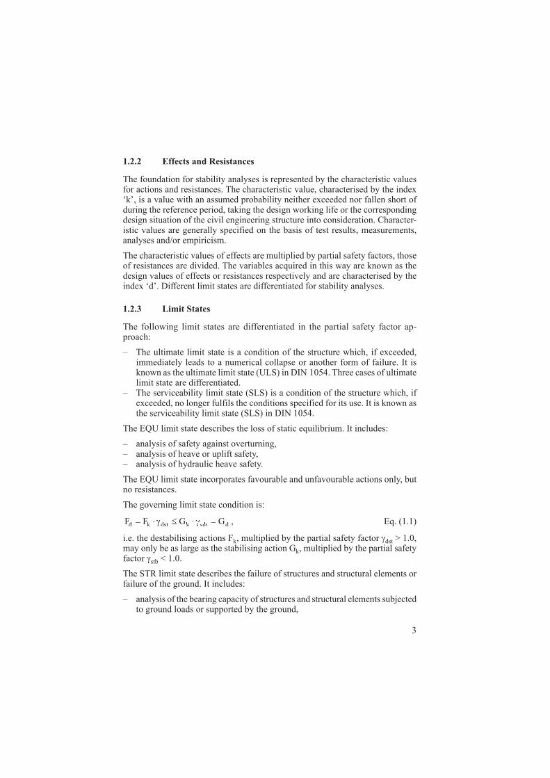
1.2.2 Effects and Resistances
The foundation for stability analyses is represented by the characteristic values for actions and resistances. The characteristic value, characterised by the index ‘k’, is a value with an assumed probability neither exceeded nor fallen short of during the reference period, taking the design working life or the corresponding design situation of the civil engineering structure into consideration. Character-istic values are generally specified on the basis of test results, measurements, analyses and/or empiricism.
The characteristic values of effects are multiplied by partial safety factors, those of resistances are divided. The variables acquired in this way are known as the design values of effects or resistances respectively and are characterised by the index ‘d’. Different limit states are differentiated for stability analyses.
1.2.3 Limit States
The following limit states are differentiated in the partial safety factor ap-proach:
– The ultimate limit state is a condition of the structure which, if exceeded, immediately leads to a numerical collapse or another form of failure. It is known as the ultimate limit state (ULS) in DIN 1054. Three cases of ultimate limit state are differentiated.
– The serviceability limit state (SLS) is a condition of the structure which, if exceeded, no longer fulfils the conditions specified for its use. It is known as the serviceability limit state (SLS) in DIN 1054.
The EQU limit state describes the loss of static equilibrium. It includes:
– analysis of safety against overturning, – analysis of heave or uplift safety, – analysis of hydraulic heave safety.
The EQU limit state incorporates favourable and unfavourable actions only, but no resistances.
The governing limit state condition is:
F F G Gd kF FF F dst k stb dGt⋅FkFF ≤ Gγ γdst kG≤ GG , Eq. (1.1)
i.e. the destabilising actions Fk, multiplied by the partial safety factor dst > 1.0, may only be as large as the stabilising action Gk, multiplied by the partial safety factor stb < 1.0.
The STR limit state describes the failure of structures and structural elements or failure of the ground. It includes:
– analysis of the bearing capacity of structures and structural elements subjected to ground loads or supported by the ground,
4
– analysis of the bearing capacity of the ground, e.g. provided by passive earth pressure or bearing resistance, to ensure it is not exceeded.
Analysis of the bearing capacity of the ground to ensure it is not exceeded is performed in exactly the same way as for any other construction material. The limit state condition is always the governing condition:
E E Rd kE F dR⋅EkE ≤γ , Eq. (1.2)
RR
dk
R=γ
, Eq. (1.3)
i.e. the characteristic action or effect Ek, multiplied by the partial safety factor F, may only be as large as the characteristic resistance Rk, divided by the partial safety factor R. A characteristic of the STR limit state is that the effects and resistances are determined using characteristic values. The partial safety factors do not come into play until applying the limit state equation.
The GEO limit state is peculiar to geotechnical engineering. It describes the loss of overall stability. It includes:
– analysis of slope stability, – analysis of global stability.
The governing limit state condition is:
d dE R , Eq. (1.4)
i.e. the design value Ed of the effects may only be as large as the design value of the resistances Rd. The geotechnical actions and resistances are determined using the design values for shear strength:
tantan′ =
′′ =
′ϕ
ϕγ γϕ
dk
dk
cand c
c, Eq. (1.5)
and
tantan
,,
,,ϕ
ϕ
γ γ,ϕ
u d,u k,
uu d,
u k,
cuand c
c= =dand c Eq. (1.6)
i.e. the friction tan and cohesion c values adopted in the calculations are reduced from the outset using the partial safety factors , u, c and cu. An analogous procedure applies to the interface friction angle and adhesion.
The serviceability limit state describes the state of a structure or structural element at which the conditions specified for its use are no longer met, but without loss of bearing capacity. It is based on a serviceability analysis, i.e. that the antici-pated displacements and deformations are compatible with the purpose of the structure. Analysis uses characteristic values, where all partial safety factors are generally 1.0.

5
1.2.4 Applying EBGEO in Conjunction with DIN EN 1997-1
This edition of EBGEO is based on the stipulations made in DIN 1054. This in turn was closely harmonised with DIN EN 1997-1, Eurocode EC 7-1. DIN 1054 is not identical to Eurocode 7-1 in all details. At the transition to Eurocode 7-1/NA EC 7-1 (see 1.2.1) DIN 1054:2005-01 will be replaced by the collateral standard DIN 1054:2010. The consequences associated with this for applying the present edition of the Recommendations are related below, as well as a preview will allow.
Legally binding rules in terms of the applicability of the individual regulations are specified by the respective controlling authorities. The controlling agencies are deemed to be:
– the building regulations control authorities of the federal German states for building measures subject to the respective state building code; at regular inter-vals the upper building regulations control authorities of the respective federal states publish a list of technical building regulations applicable to that state.
– the departments of the Federal Ministry of Transport, Building and Urban Affairs responsible for inland waterways, federal roads and road bridges, and the Federal Railway Authority responsible for rail traffic.
Stability analyses as described in Section 1.2.3, Eurocode EC 7-1, provide three options in terms of the STR limit state. DIN 1054 is based on analysis procedure 2 to Eurocode EC 7-1, inasmuch as the partial safety factors are applied to both the effects and the resistances. To differentiate between this and the other permitted scenario, in which the partial safety factors are not applied to the effects but to the actions, this procedure is known as analysis method 2* in the Commentary to Eurocode EC 7-1.
The National Annex represents the link between Eurocode EC 7-1 and national standards. It states which of the possible analysis methods and partial safety factors are applicable in the respective national domains. Remarks, clarifications or supplements to Eurocode EC 7-1 are not permitted. However, the applicable, complementary national codes may be given. The complementary national codes may not, however, contradict Eurocode EC 7-1. Moreover, the National Annex may not repeat information already given in Eurocode EC 7-1.
The revised DIN 1054 will be paramount in the complementary national code; it has the working title ‘DIN 1054:2010’ and is the application rule to Eurocode EC 7-1.
The supplements, improvements and modifications included shall be adhered to inasmuch as they affect the regulations of the EBGEO, if the respective geosyn-thetic-reinforced structure is designed to Eurocode EC 7-1. However, they may also be utilised accordingly if design is based on DIN 1054.
In the current edition Eurocode EC 7-1 defines the following limit states instead of the limit states GZ 1A, GZ 1B and GZ 1C to DIN 1054:

6
– EQU: loss of equilibrium of the structure or the ground, which is regarded as rigid. The designation is derived from ‘equilibrium’.
– STR: internal failure or very large deformation of the structure or its compo-nents, where the strength of the materials governs resistance. The designation is derived from ‘structural failure’.
– GEO: failure or very large deformation of the structure or the ground, where the strength of the soil or rock governs resistance. The designation is derived from ‘geotechnical failure’.
– UPL: loss of equilibrium of the structure or ground due to buoyancy or water pressure. The designation is derived from ‘uplift’.
– HYD: hydraulic failure, internal erosion or piping in the ground, caused by a flow gradient. The designation is derived from ‘hydraulic failure’.
In order to convey the GZ 1B und GZ 1C (STR and GEO) limit states from DIN 1054 to the terminology used in Eurocode EC 7-1 the GEO limit state is divided into GEO-2 and GEO-3:
– GEO-2: failure or very large deformation of the ground in conjunction with determining the action effects and dimensions; i.e. when utilising the shear strength for passive earth pressure or bearing resistance. The GEO-2 limit state comprises analysis method 2* to Eurocode EC 7-1.
– GEO-3: failure or very large deformation of the ground in conjunction with analysis of overall stability, i.e. when utilising the shear strength for analysis of slope stability and global stability and, generally, when analys-ing the stability of engineered slope stabilisation measures, including that of structural elements. The GEO-3 limit state comprises analysis method 3 to Eurocode EC 7-1.
The previous limit states are replaced as follows:
– The previous limit state GZ 1A to DIN 1054 now corresponds without restric-tions to the EQU, UPL and HYD limit states to Eurocode EC 7-1.
– The previous GZ 1B limit state to DIN 1054 now corresponds in all facets to the Eurocode EC 7-1 STR limit state. The GEO-2 limit state to Eurocode EC 7-1 is also used in conjunction with the design dimensions for founda-tion elements.
– The previous GZ 1C limit state to DIN 1054 corresponds to the GEO-3 limit state to Eurocode EC 7-1 in conjunction with analysis of overall stability.
Analyses of the stability of engineered slope stabilisation measures are always allocated to the GEO limit state. Depending on the engineering design and func-tion (see DIN 1054) they may be dealt with either according to the previous GZ 1B limit state or the GEO-2 limit state, or according to the previous GZ 1C limit state or the GEO-3 limit state. The geosynthetic material is designed for the STR limit state.