Embed Size (px)
Citation preview

Rev. 0.2 3/12 Copyright © 2012 by Silicon Laboratories AN664
AN664
PRECISION32™ CMSIS AND HAL USER’S GUIDE
1. Introduction
CMSIS is the Cortex Microcontroller Software Interface Standard, and the Hardware Access Layer (HAL) is adefined part of this standard.
The HAL provides an access layer for the SiM3xxxx device registers. The functions and macros are non-blockingand simple; they cannot return error codes, so they are designed to never fail. The HAL is designed to replace theindividual bit field accesses of the module with a function name that describes the action the bit is controlling.
Note: HAL functions and macros are not designed to be thread-safe. These routines do not disable interrupts during non-monotonic register modifications.
The HAL is one layer above the hardware and is the only code that accesses the registers directly. More complexfirmware systems like a Real Time Operating System (RTOS) or code example call the HAL and CMSIS routines.
Figure 1 shows the Precision32™ firmware layer block diagram.
Figure 1. Firmware Layer Block Diagram
2. Relevant Documentation
Precision32 Application Notes are listed on the following website: www.silabs.com/32bit-appnotes.
AN668: Precision32™ Software Development Kit (SDK) Code Examples Overview
AN670: Getting Started with the Silicon Labs Precision32™ AppBuilder
AN672: Precision32™ si32Library Overview
AN673: Precision32™ Software Development Kit Overview
AN675: Precision32™ Development Suite Overview
Callback
CMSIS
RTOS
si32Library
APPLICATION
CMSIS CoreSupport from ARM
HAL from Silicon Labs
CODE EXAMPLES
HARDWARE

AN664
2 Rev. 0.2
3. Peripheral Memory Organization
Each peripheral exists as a set of registers in memory. Most peripherals start at 0x1000 address blocks in theperipheral memory area starting at address 0x4000_0000. The base pointer of a peripheral points to the startingaddress of the peripheral, and each register is an offset from the base address. In the case of the USART0 module,the base pointer is SI32_USART_0, and it is assigned an address of 0x4000_0000, since it’s the first peripheral inthe peripheral memory area.
The registers each take 16 bytes (0x10) of memory: a word each for the register and the SET, CLR, and MSKaddresses. These addresses are reserved for registers that do not implement them.
Figure 2 shows the USART0 registers as they appear in memory.
Figure 2. USART0 Registers in Memory
SiM3xxxx Address Space
CONFIG
CONFIG_SET
CONFIG_CLR
SI32_USART_0 0x4000_00000x4000_00040x4000_00080x4000_000C0x4000_0010MODE
MODE_SET
MODE_CLR
FLOWCN
FLOWCN_SET
FLOWCN_CLR
0x4000_00140x4000_00180x4000_001C0x4000_00200x4000_00240x4000_00280x4000_002C

AN664
Rev. 0.2 3
4. HAL Organization
The HAL is organized based on the SiM3xxxx peripheral modules. Modules of the same type and revision areexactly the same, so these modules share the same generic description. The individual instances of the modulesthen instantiate their own copies of the generic description. For example, the HAL implements a USART (module)A (revision) type. This type is then instantiated multiple times for USART0 and USART1, which have their ownbase pointers.
Each generic module has a *_Registers.h file that contains a module structure comprised of register structures andbit fields properly aligned in memory. The *_Type.h file contains the HAL interface for the module, and the *_Type.ccontains the HAL implementation. Some modules will also have a *_Support.h file that contains helpfulenumeration definitions. Finally, a device header file named for the device (e.g., sim3u1xx.h) contains base pointerand interrupt vector instantiations for each module on a device.
Figure 3 displays a block diagram showing the relationship of the HAL files.
Figure 3. HAL Block Diagram
Interrupt Vectors Base Pointers
sim3u1xx.h
Module
Register and Bit Definitions
Registers.h
Function Prototypes and
Macros
Type.h
Functions
Type.c
Enumerated Type Definitions
Support.h

AN664
4 Rev. 0.2
4.1. USART0 HAL ExampleThe sim3u1xx.h device file contains the USART0 interrupt vector (USART0_IRQn) and base pointer information(SI32_USART_0). The SI32_USART_A_Registers.h file contains the module structure, which includes structuresof bit fields for each register. The SI32_USART_A_Type.h and Type.c files contain routines that access each ofthese bits.
Figure 4 displays a block diagram showing the relationship of the HAL files for the USART0 module.
Figure 4. Example USART HAL Block Diagram
Firmware can call the USART0 select tx parity routine using the base pointer defined in si3mu1xx.h and thefunction implemented in SI32_USART_A_Type.c:
SI32_USART_A_select_tx_parity(SI32_USART_0, parity);
Interrupt Vector: USART0_IRQnBase Pointer: SI32_USART_0
sim3u1xx.h
USART0
void_SI32_USART_A_select_tx_parity( SI32_USART_A_Type * basePointer, uint32_t parity){ assert(parity < 4); // parity < 2^2 //{{ basePointer->CONFIG_CLR = SI32_USART_A_CONFIG_TPARMD_MASK; basePointer->CONFIG_SET = parity << SI32_USART_A_CONFIG_TPARMD_SHIFT; //}}}
SI32_USART_A_Type.c
void_SI32_USART_A_select_tx_parity( SI32_USART_A_Type * basePointer, uint32_t parity);
SI32_USART_A_Type.h
CONFIG.TPARMD
#define SI32_USART_A_CONFIG_TPARMD_MASK 0x00600000#define SI32_USART_A_CONFIG_TPARMD_SHIFT 21// Odd Parity.#define SI32_USART_A_CONFIG_TPARMD_ODD_VALUE 0#define SI32_USART_A_CONFIG_TPARMD_ODD_U32 \ (SI32_USART_A_CONFIG_TPARMD_ODD_VALUE << SI32_USART_A_CONFIG_TPARMD_SHIFT)...
SI32_USART_A_Registers.h

AN664
Rev. 0.2 5
Table 1 shows an example set of registers for the USART0 module.
Figure 5 illustrates the resulting USART module structure in Registers.h.
Figure 5. Example USART Module Structure
Table 1. Example USART Registers
Register Name TitleAddress
(ALL Access)
SE
T (
+0
x4)
CL
R(+
0x
8)
MS
K (
+0x
C)
USART0 Registers
USART0_CONFIG Module Configuration 0x4000_0000 Y Y
USART0_MODE Module Mode Select 0x4000_0010 Y Y
USART0_FLOWCN Flow Control 0x4000_0020 Y Y
USART0_CONTROL Module Control 0x4000_0030 Y Y
USART0_IPDELAY Inter-Packet Delay 0x4000_0040
USART0_BAUDRATE Transmit and Receive Baud Rate 0x4000_0050
USART0_FIFOCN FIFO Control 0x4000_0060 Y Y
USART0_DATA FIFO Input/Output Data 0x4000_0070

AN664
6 Rev. 0.2
Each of the registers has a corresponding structure that defines the bit fields within that register. In addition,registers that implement the clear and set addresses have 32-bit variables defined at the appropriate addresses.
Figure 6 shows the CONFIG register structure, which is declared as a part of the USART module structure.
Figure 6. Example USART CONFIG Register Structure
This CONFIG register structure has the TPARMD 2-bit field that controls the transmit parity. The U32 valuedeclared at the bottom of the structure is a union with the bit fields and is an entity that firmware can use to accessthe entire register at one time.
The HAL Type.c functions and macros can access the entire USART0 CONFIG register:
SI32_USART_0->CONFIG.U32 = config;
The HAL can also read or write the TPARMD field in the USART0 CONFIG register:
parity = SI32_USART_0->CONFIG.TPARMD;
SI32_USART_0->CONFIG_SET = parity << SI32_USART_A_CONFIG_TPARMD_SHIFT;
Finally, the HAL can clear the TPARMD field:
SI32_USART_0->CONFIG_CLR = SI32_USART_A_CONFIG_TPARMD_MASK;
AN664
Rev. 0.2 7
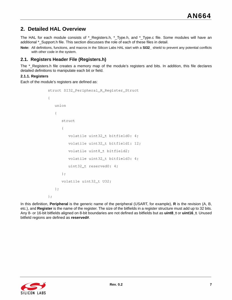
2. Detailed HAL Overview
The HAL for each module consists of *_Registers.h, *_Type.h, and *_Type.c file. Some modules will have anadditional *_Support.h file. This section discusses the role of each of these files in detail.
Note: All definitions, functions, and macros in the Silicon Labs HAL start with a SI32_ shield to prevent any potential conflictswith other code in the system.
2.1. Registers Header File (Registers.h)The *_Registers.h file creates a memory map of the module’s registers and bits. In addition, this file declaresdetailed definitions to manipulate each bit or field.
2.1.1. Registers
Each of the module’s registers are defined as:
struct SI32_Peripheral_R_Register_Struct
{
union
{
struct
{
volatile uint32_t bitfield0: 4;
volatile uint32_t bitfield1: 12;
volatile uint8_t bitfield2;
volatile uint32_t bitfield3: 4;
uint32_t reserved0: 4;
};
volatile uint32_t U32;
};
};
In this definition, Peripheral is the generic name of the peripheral (USART, for example), R is the revision (A, B,etc.), and Register is the name of the register. The size of the bitfields in a register structure must add up to 32 bits.Any 8- or 16-bit bitfields aligned on 8-bit boundaries are not defined as bitfields but as uint8_t or uint16_t. Unusedbitfield regions are defined as reserved#.

AN664
8 Rev. 0.2
FIFO registers are not defined using any bitfields. If byte accesses are not allowed, the register structure does notinclude a uint8_t definition. The same applies to half-word accesses and the uint16_t definition. All FIFOs areaccessed from the least significant byte, so there is no explicit access provided for the upper three bytes or theupper half-word.
struct SI32_Peripheral_R_Register_Struct
{
union
{
volatile uint8_t U8;
volatile uint16_t U16;
volatile uint32_t U32;
};
};
2.1.2. Bitfields
Each of the bitfields of a module has several defines in the *_Registers.h file. These defines all have the formSI32_Module_Revision_Register_Bitfield_DefineType. The DefineType is:
MASK: a bit mask for the position of the bit or field in the register.
SHIFT: a left-shift value for the position of the bit or field in the register.
Enumeration_VALUE or Enumeration_U32: These enumerations define every valid value of the bit or field. The enumerations also include a U32 version that the HAL routines can write to entire register using the defined SHIFT value.
For example, with the IPRDY bit in the EPCONTROL register (bit 0) of the USBEP module:
#define SI32_USBEP_A_EPCONTROL_IPRDYI_MASK 0x00000001
#define SI32_USBEP_A_EPCONTROL_IPRDYI_SHIFT 0
// The packet has been sent or there is an open FIFO slot.
#define SI32_USBEP_A_EPCONTROL_IPRDYI_NOT_SET_VALUE 0
#define SI32_USBEP_A_EPCONTROL_IPRDYI_NOT_SET_U32 \ (SI32_USBEP_A_EPCONTROL_IPRDYI_NOT_SET_VALUE << SI32_USBEP_A_EPCONTROL_IPRDYI_SHIFT)
// A packet is loaded in the FIFO.
#define SI32_USBEP_A_EPCONTROL_IPRDYI_SET_VALUE 1
#define SI32_USBEP_A_EPCONTROL_IPRDYI_SET_U32 \ (SI32_USBEP_A_EPCONTROL_IPRDYI_SET_VALUE << SI32_USBEP_A_EPCONTROL_IPRDYI_SHIFT)
The NOT_SET and SET definitions are the enumerations for this bit. The VALUE definitions set the value of eachvalid bit value, and the U32 definitions are the appropriate write value for the bit when writing to entire register.

AN664
Rev. 0.2 9
2.1.2.1. Using the MASK Definition
The HAL uses MASK definitions to clear or set bitfields in registers that support clear and set addresses. In thesecases, the address can be set equal to the mask directly to manipulate the bitfield. For example:
void
_SI32_USART_A_disable_rx_start_bit(SI32_USART_A_Type * basePointer)
{
//{{
basePointer->CONFIG_CLR = SI32_USART_A_CONFIG_RSTRTEN_MASK;
//}}
}
2.1.2.2. Using the SHIFT Definition
The HAL uses the SHIFT definition when a field value is passed to a routine. This allows the calling code to pass ina raw value, and the HAL can handle the actual placement of the bitfield in the register. For example:
void
_SI32_USART_A_select_rx_stop_bits(SI32_USART_A_Type * basePointer, SI32_USART_A_STOP_BITS_Enum_Type bits)
{
assert(bits < 4); // bits < 2^2
//{{
basePointer->CONFIG_CLR = SI32_USART_A_CONFIG_RSTPMD_MASK;
basePointer->CONFIG_SET = bits << SI32_USART_A_CONFIG_RSTPMD_SHIFT;
//}}
}
2.1.2.3. Using the Enumeration Definitions
The HAL uses the U32 enumeration definitions for the clear and set addresses or when accessing the entireregister. The HAL does not use the value definitions themselves whenever possible, since accessing a singlebitfield in a register is inefficient. For example:
void
_SI32_USART_A_enable_rx_error_interrupts(SI32_USART_A_Type * basePointer)
{
//{{
basePointer->CONTROL_SET = SI32_USART_A_CONTROL_RERIEN_ENABLED_U32;
//}}
}
AN664
10 Rev. 0.2
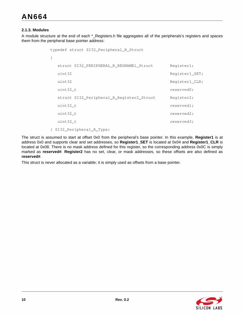
2.1.3. Modules
A module structure at the end of each *_Registers.h file aggregates all of the peripherals’s registers and spacesthem from the peripheral base pointer address:
typedef struct SI32_Peripheral_R_Struct
{
struct SI32_PERIPHERAL_R_REGNAME1_Struct Register1;
uint32 Register1_SET;
uint32 Register1_CLR;
uint32_t reserved0;
struct SI32_Peripheral_R_Register2_Struct Register2;
uint32_t reserved1;
uint32_t reserved2;
uint32_t reserved3;
} SI32_Peripheral_R_Type;
The struct is assumed to start at offset 0x0 from the peripheral’s base pointer. In this example, Register1 is ataddress 0x0 and supports clear and set addresses, so Register1_SET is located at 0x04 and Register1_CLR islocated at 0x08. There is no mask address defined for this register, so the corresponding address 0x0C is simplymarked as reserved#. Register2 has no set, clear, or mask addresses, so these offsets are also defined asreserved#.
This struct is never allocated as a variable; it is simply used as offsets from a base pointer.

AN664
Rev. 0.2 11
2.2. Type Header (Type.h) and Code (Type.c) FilesThe *_Type.h file creates the interface definition of the module. This file includes function prototypes and macrodefinitions for each of the HAL routines. Including this file in a source file means that file now has access to all ofthe HAL routines for a module.
The *_Type.c file is the implementation of the module HAL functions. This file includes all of the functiondeclarations for the prototypes in the *_Type.h file.
Each of the routines starts with the SI32_ shield and the module name. The descriptive name of the function thenfollows. For example, the routine to set the IPRDYI bit in the USBEP module is:
void _SI32_USBEP_A_set_in_packet_ready(SI32_USBEP_A_Type * basePointer);
2.2.1. Function Naming
The function names for the HAL follow a set of guidelines to make them consistent and predictable acrossmodules:
Names are in lower case, including acronyms: read_nss_pin.
Do not use abbreviations, with one exception being tx for transmit and rx for receive.
Separate words using underscores.
Use enable_module and disable_module for bits that control the whole module.
Use reset_module for bits that reset the whole module.
Use select for functions that are selecting an item that is mutually exclusive from other options. This is common with settings that involve multiple bitfields.
Use enter_mode_description_mode and exit_mode_description_mode for non-mutually exclusive items, and all enter_mode functions must have an exit_mode counterpart. For example, to enter the IrDA mode in the USART module: enter_rx_irda_mode.
Use set, get, and clear for bits and registers. For example: set_parity_even, get_status, clear_carry_flag.
Use numerical value for numbers. For example: set_fifo_threshold_1, set_fifo_threshold_2.
Use read and write when manipulating data or pins. For example: read_fifo, write_fifo, read_nss_pin.
Use start and stop for things that run, like oscillators and timers.
Use enable, disable, “is enabled”, “is pending”, and clear for interrupts. For example: enable_overrun_interrupt, disable_overrun_interrupt, is_overrun_interrupt_pending, and clear_overrun_interrupt.
Use has for events that have flags but do not cause interrupts. For example: has_buffer_overflow_occurred.
For debug bits, use the enable_stall_in_debug_mode and disable_stall_in_debug_mode routine names.
Functions referring to the peripheral should always use the module keyword.
AN664
12 Rev. 0.2
2.2.2. Required Functions
Each module must have the following functions:
initialize
enable_module whenever a corresponding bit exists
disable_module whenever a corresponding bit exists
reset_module whenever a corresponding bit exists
A write_<register> function for each register
A read_<register> function for each register
enable_<interrupt>_interrupt for each interrupt
disable_<interrupt>_interrupt for each interrupt
is_<interrupt>_interrupt_enabled for each interrupt
is_<interrupt>_interrupt_pending for each interrupt
clear_<interrupt>_interrupt for each interrupt
The initialize function takes all writable registers as parameters and copies them into the registers. This function isknowledgeable about order, whenever order matters.
The write register functions take the register value as a parameter and copies it into the register. The read registerfunctions return the value of the register.
2.2.3. Return and Parameter Types
Return types must be one of the following:
void
bool
uint32_t
uint16_t
uint8_t
Enumeration Type defined for the module in *_Support.h
When returning a bool value, the functions explicitly typecast the return value as a bool.
Parameters must be one of the following:
uint32_t
uint16_t
uint8_t
bool
Enumeration Type defined for the module in *_Support.h
The functions use these types for all parameters used to carry values that are smaller than 32 bits but are passedwide for efficiency:
wide8_t: value can be converted to signed 8-bit number without loss of precision
uwide8_t: value can be converted to unsigned 8-bit number without loss of precision
wide16_t: value can be converted to signed 16-bit number without loss of precision
uwide_16_t: value can be converted to unsigned 16-bit number without loss of precision
These types indicate to the calling code that, while the parameter is passed wide, the actual value will be storednarrow in the indicated storage format.
AN664
Rev. 0.2 13
2.2.4. Function Implementation Guidelines
Functions do not block or return error codes. This serves several purposes:
1. This eliminates the need for the HAL to validate parameters, beyond debug bounds assertions.
2. This eliminates the need for the calling code to validate the return codes.
If a function could not be safely implemented without polling, such as enabling an external oscillator, then it is not aHAL function. This functionality is left to a higher level of firmware, like the si32Library or AppBuilder.
Functions are not allowed to allocate memory locally or use global variables. As a result, the functions will not beable to maintain state separate from what is maintained in the registers themselves.
Functions are as efficient as possible. For set or clear operations, functions use the set or clear addresses, whereapplicable. Read-modify-write operations are used only when absolutely necessary when clearing a field beforesetting it to a new value causes an issue, like undesired pin transitions.
All functions have four or fewer parameters whenever possible, including the base pointer to the module.
2.3. Optional Support Files (Support.h)The *_Support.h files are optional for a module and share the same basic template as *_Type.h files. These filescontain helpful enumerations for modules and any other support code necessary. The format for theseenumerations is:
typedef enum SI32_Peripheral_Struct
{
SI32_Peripheral_EnumName1 = 0,
SI32_Peripheral_EnumName2 = 1,
...
} SI32_Peripheral_Enum_Type;
The enumerations provide set values for a function parameter to eliminate the chance of using an invalid value andto make code more readable. For example:
typedef enum SI32_RSTSRC_Struct
{
SI32_RSTSRC_PIN_RESET = 0,
SI32_RSTSRC_POWER_ON_RESET = 1,
SI32_RSTSRC_VDD_MONITOR = 2,
...
} SI32_RSTSRC_Enum_Type;
The get_last_reset_source routine can then return a value of this enumeration type:
SI32_RSTSRC_Enum_Type _SI32_RSTSRC_A_get_last_reset_source( SI32_RSTSRC_A_Type * basePointer);
Firmware can then decode the return value of this routine using the enumeration values defined inSI32_RSTSRC_A_Support.h to create readable and less error-prone code.

AN664
14 Rev. 0.2
2.4. HAL Startup CodeThe si32Hal startup implementation differs from the CMSIS recommendation in order to support multiple toolchains. Each individual application has explicit control over all of its memory model, including the stack, heap,RAM, retention RAM, and EMIF. The symbols used to define the base and size of these memory areas is availablefor use by the application without duplication.
The HAL uses tool chain-specific linker control files in the si32-x.y\si32Hal\device directory to specify theseranges. These files are:
GCC/Precision32: linker_DeviceFamily_p32.ld
ARM: linker_DeviceFamily_arm.sct
IAR: linker_DeviceFamily_iar.icf
The code examples also provide basic linker control files that are sufficient for many applications. For cases wherethese linker files are not sufficient, the application developer should use application-specific linker files.
3. Performance
The HAL implements both macros and functions for most routines. This allows firmware layers that call the HAL tochoose between the faster performance of macros or the smaller footprint of functions. For the routines that do nothave an implemented macro, a macro still exists, but it just calls the function.
The functions and macros have the same parameters and names, but functions have an underscore prefix. Forexample, the function for setting the USART transmit parity is:
_SI32_USART_A_select_tx_parity(SI32_USART_0, parity);
The macro for the same routine is:
SI32_USART_A_select_tx_parity(SI32_USART_0, parity);
4. Revisions
Each version of the HAL sits in a separate folder. The path of these is C:\SiLabs\32bit\si32\si32-x.y, where x isthe primary HAL version and y is the secondary HAL version. Each time a new version of the HAL is installed, it willleave all previous versions to eliminate the chance of a new install breaking a working firmware project.
In addition, any deprecated functions will remain a part of the HAL. These functions will either remain unchangedor call the new version to prevent the need to modify firmware when migrating to a newer version of the HAL.
5. Code Examples
Each version of the HAL includes stand-alone code examples for the device modules that use the macro routinesby default. These examples can be found in C:\SiLabs\32bit\si32-x.y\Examples after installing the Precision32IDE.
6. The HAL and AppBuilder
The Silicon Labs AppBuilder program uses HAL macros when configuring peripherals. The AppBuilder projectoptions can select between different versions of the HAL.

AN664
Rev. 0.2 15
7. Detailed Documentation
The detailed Silicon Labs CMSIS documentation can be found in the si32Hal Windows help file (si32Hal.chm). Thedocumentation includes the Cortex-M3 Core Register Definitions, Core Function Interface, and Core InstructionInterface, as well as the SiM3xxxx HAL.
The si32Hal file shown in Figure 7 is installed in C:\SiLabs\32bit\si32-x.y\Documentation after installing thePrecision32 software package from www.silabs.com/32bit-software.
Figure 7. Silicon Labs HAL and CMSIS Documentation

AN664
16 Rev. 0.2
DOCUMENT CHANGE LIST
Revision 0.1 to Revision 0.2Updated Figure 1.
Updated the name of the HAL help file to si32Hal.chm.
Added Section 2.

http://www.silabs.com
Silicon Laboratories Inc.400 West Cesar ChavezAustin, TX 78701USA
Simplicity Studio
One-click access to MCU and wireless tools, documentation, software, source code libraries & more. Available for Windows, Mac and Linux!
IoT Portfoliowww.silabs.com/IoT
SW/HWwww.silabs.com/simplicity
Qualitywww.silabs.com/quality
Support and Communitycommunity.silabs.com
DisclaimerSilicon Labs intends to provide customers with the latest, accurate, and in-depth documentation of all peripherals and modules available for system and software implementers using or intending to use the Silicon Labs products. Characterization data, available modules and peripherals, memory sizes and memory addresses refer to each specific device, and "Typical" parameters provided can and do vary in different applications. Application examples described herein are for illustrative purposes only. Silicon Labs reserves the right to make changes without further notice and limitation to product information, specifications, and descriptions herein, and does not give warranties as to the accuracy or completeness of the included information. Silicon Labs shall have no liability for the consequences of use of the information supplied herein. This document does not imply or express copyright licenses granted hereunder to design or fabricate any integrated circuits. The products are not designed or authorized to be used within any Life Support System without the specific written consent of Silicon Labs. A "Life Support System" is any product or system intended to support or sustain life and/or health, which, if it fails, can be reasonably expected to result in significant personal injury or death. Silicon Labs products are not designed or authorized for military applications. Silicon Labs products shall under no circumstances be used in weapons of mass destruction including (but not limited to) nuclear, biological or chemical weapons, or missiles capable of delivering such weapons.
Trademark InformationSilicon Laboratories Inc.® , Silicon Laboratories®, Silicon Labs®, SiLabs® and the Silicon Labs logo®, Bluegiga®, Bluegiga Logo®, Clockbuilder®, CMEMS®, DSPLL®, EFM®, EFM32®, EFR, Ember®, Energy Micro, Energy Micro logo and combinations thereof, "the world’s most energy friendly microcontrollers", Ember®, EZLink®, EZRadio®, EZRadioPRO®, Gecko®, ISOmodem®, Precision32®, ProSLIC®, Simplicity Studio®, SiPHY®, Telegesis, the Telegesis Logo®, USBXpress® and others are trademarks or registered trademarks of Silicon Labs. ARM, CORTEX, Cortex-M3 and THUMB are trademarks or registered trademarks of ARM Holdings. Keil is a registered trademark of ARM Limited. All other products or brand names mentioned herein are trademarks of their respective holders.