Embed Size (px)
Citation preview
Sadhana Vol. 28, Parts 3 & 4,June/August 2003, pp. 395–408. © Printed in India
Recent trends in repair and refurbishing of steam turbinecomponents
A K BHADURI, S K ALBERT, S K RAY and P RODRIGUEZa
Indira Gandhi Centre for Atomic Research, Kalpakkam 603102, IndiaaPresent address: Recruitment and Assessment Centre, Defence Research andDevelopment Organisation, Lucknow Road, Timarpur, New Delhi 110 054, Indiae-mail: [email protected]
Abstract. The repair and refurbishing of steam generator components is discussedfrom the perspective of repair welding philosophy including applicable codes andregulations. Some case histories of repair welding of steam generator componentsare discussed with special emphasis on details of repair welding of cracked steamturbine blades and shrouds in some of the commercial nuclear power plants usingprocedures developed.
Keywords. Repair welding; steam turbine components; repair philosophy;codes and regulations; case histories.
1. Introduction
Reliability of an engineering component requires that quality orfitness-for-purposeaspectsbe adequately addressed at various stages of its design and fabrication. Both economic andsafety considerations influence the quality, and hence the reliability of a system. Economicsdictate the competitiveness of the product, while safety requires the smooth functioning of thecomponent without hazard to personnel and property. It is possible to build a highly reliableengineering system but it may not be economically competitive. On the other hand, if reliabilityis poor the component may violate safety standards. Therefore, features are specified toincorporatefitness-for-serviceattributes at the design stage. This means that each componentshould be (a) designed to meet the service requirements for the required life, (b) fabricatedwith specified materials, conforming to design concepts and inspection standards, and (c)operated and maintained properly. Despite incorporation of concepts of quality or fitness-for-service, engineering components are known to fail prematurely. In order to constantly monitorthe health of a system and to avoid sudden and unexpected failure, advanced concepts of in-service inspection, prediction of remnant life and preventive maintenance of components arebecoming increasingly important.
The term failure, as applied to engineering systems, can be described as non-performanceof components or systems due to some deficiency that limits their service life. Failures arenot uncommon in industry and can occur at any of the various stages such as fabrication,testing, transportation and service. Failures can be broadly classified asend-of-life failuresthat are predictable and for which proper preventive actions could be taken in advance, and
395
396 A K Bhaduri et al
premature failuresthat are unpredictable and occur without sufficient warning. The latter maylead to plant shutdown, loss in production and productivity, fire explosion, radiation or gasleak or in extreme cases may end up in catastrophes resulting in loss of life and/or damage toproperty and environment. These sudden failures may also adversely affect the morale of theworkforce and their confidence in the safety of the system. Two such industrial accidents thatled to heavy loss of life and damage to environment are the Bhopal gas leak and Chernobylnuclear accident.
Welding is an important and reliable joining process; all joints introduce discontinuitiesand gradients and affect safe operation of components. It is for this reason that welds areconsidered weak links. A large number of failures in industry are either directly or indirectlyattributed to welds. Moreover, a vast majority of repairs of failed components is carried outusing one of the welding processes. Since repair of each failure requires a different strategy,codes and standards provide only general guidelines, and it is essential to consult a competentWelding Technology Group to carry out successful repairs.
Once a component fails, it is important to take “time-critical” decisions to put back the sys-tem in operation without much delay. One of the options is to replace the damaged or failedcomponent. Often, this is a very expensive and time-consuming option. Repair rather thanreplacement can achieve substantial reduction in downtime and cost. Repair welding is oneof the most common methods employed in industry to salvage defective, damaged or failedcomponents. However, success of repair-welding operations depends on many factors suchas weldability of the material, type of damage, availability of a suitable welding techniqueand welding consumable, possibility of carrying out preheating and post-weld heat treatment(PWHT), post-repair inspection by non-destructive testing (NDT) techniques etc. Occasion-ally, the welding process and/or welding consumable for repair may be different from thoseused for the original fabrication. A typical example is the repair of a submerged arc weldusing the shielded metal arc welding process. Care should be taken that the differences inthe heat input employed and the composition of the welding consumables do not introducedefects during repair. Weld repair of components failed in service is more complex than repaircarried out to remove defects noticed during fabrication. Proper analysis of the failure shouldbe carried out before attempting a repair. Failure might have occurred because of faults indesign, fabrication or manufacturing, wrong selection of material or operational mistakes.Unless the real cause of the failure is identified and removed, the repair might prove to beonly a temporary solution.
Depending on the specific application any of the common welding processes like shieldedmetal arc welding (SMAW), gas metal arc welding (GMAW), gas tungsten arc welding(GTAW), submerged arc welding (SAW) etc. may be used. For very high quality welds, theGTAW process finds the widest application. SAW and GMAW may be advantageous for longweld runs or when large amount of weld metal has to be deposited, and where mechanisationis feasible. The GMAW process is chosen for remote repairs carried out with robots due toamenability to automation. This is of special importance to repair welding in nuclear rectorswhere high radiation levels often restrict human access to the repair site. For general-purposerepairs, the SMAW process enjoys a dominant position for out-of-position welding and shortweld runs, especially when time is critical and portable equipment is available.
When one thinks about welding repairs, the first reaction is to deal with the type of repair,in other words, to concentrate on welding engineering aspects which need to be fixed andchecked. This reaction is understandable, but is usually wrong. One has to differentiatebetween manufacturing-related and operation-related failures. With manufacturing-relatedfailures one always has the design plan to refer back to as a benchmark, and these failures are
Repair of steam turbine components 397
usually due to inadmissible pores or slag inclusions, misalignment, forced ruptures, relaxationcracks, hydrogen-induced cracking, lamellar tearing etc. On the other hand, with operation-related failures, solution by change in the design is usually not possible as this type of failureis not normally linked to welding, but is caused by wear, corrosion, cavitation etc. There arevarying repair strategies that can be adopted depending on the type of defect and its possiblecause (Gnirss 1992).
2. Repair philosophy
There are certain guidelines and rules available for repair of large components and structures(Malin & Fields 1992).
(1) Repair of a large component is typically of an urgent and critical nature since the failure ofthe component may have a devastating effect on industrial or financial activity, jeopardisehuman safety, and have serious economic impact.
(2) In most cases, the only alternative to repair is the replacement of a substantial portion ofthe component or even the entire component. This is usually associated with considerablereplacement cost, prolonged schedule disruption and, therefore, considerable financialburden.
(3) Repair is typically required to be performed in the field under unfavourable conditionsin a very compressed time frame, which demands much subjective on-the-spot humanintervention (in contrast to fabrication of a new component).
(4) Many large components can only be repaired once without facing the risk of significantdamage to the component.
Repair welding, in actual implementation, involves three basic stages: analysis, develop-ment and performance.Analysis may include the determination of the possible cause of failureand the assessment of a stress situation in the area to be repaired. The development stage mayinclude an evaluation of the component design and the amenability of that design for repairwelding and development of repair approach, as also the main requirements and detailed spec-ification for assembling, welding and inspection. The performance stage includes all repairactivities at a shop and/or in the field.
The objective of repair welding is to extend the service life of failed components. Inpractice, there are two typical approaches to meeting this objective,research-orientedandrepair-oriented. In the former, the main emphasis is on failure and/or stress analysis, whichsometimes accounts for a disproportionately large portion of the repair budget. Study ofthe probable cause of failure turns into extensive failure and metallurgical analyses, and thedetermination of stresses in a failed area can become an elaborate stress analysis exercise.Unfortunately, the data obtained will rarely find their way into a repair approach or a weldingprocedure. There is, however, a danger in the process as the focus of such analysis, viz. toprovide support for repairs, may be lost. Considering the high cost and time of such an analysis,the main objective should be to generate adequate input data to support the development ofa comprehensive and realistic approach and welding procedure.
In contrast, the repair-oriented approach is more typical of fabrication and repair shops.The main emphasis here is on the performance stage of repair, while the analysis stage is(almost) neglected. Unfortunately, in both approaches the developmental stage and thus thewelding engineering aspects of a repair are not given adequate attention. AWelding Technol-ogy Groupis an important link between a research organisation, which lacks performance
398 A K Bhaduri et al
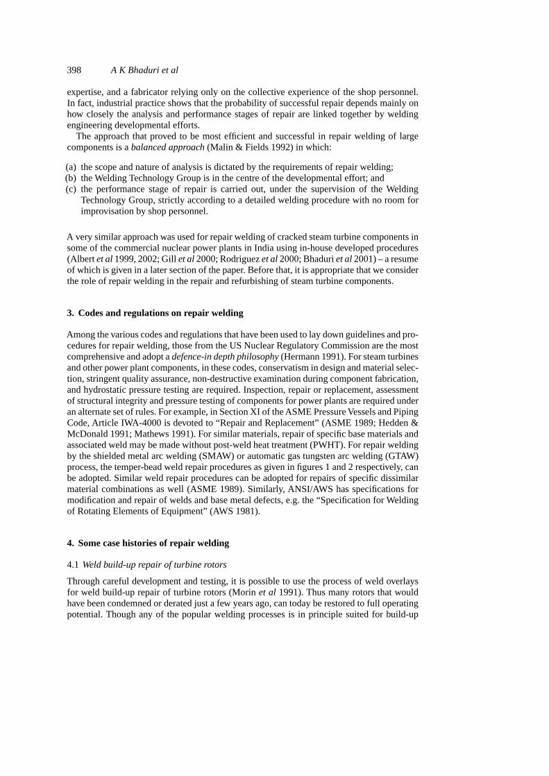
expertise, and a fabricator relying only on the collective experience of the shop personnel.In fact, industrial practice shows that the probability of successful repair depends mainly onhow closely the analysis and performance stages of repair are linked together by weldingengineering developmental efforts.
The approach that proved to be most efficient and successful in repair welding of largecomponents is abalanced approach(Malin & Fields 1992) in which:
(a) the scope and nature of analysis is dictated by the requirements of repair welding;(b) the Welding Technology Group is in the centre of the developmental effort; and(c) the performance stage of repair is carried out, under the supervision of the Welding
Technology Group, strictly according to a detailed welding procedure with no room forimprovisation by shop personnel.
A very similar approach was used for repair welding of cracked steam turbine components insome of the commercial nuclear power plants in India using in-house developed procedures(Albertet al1999, 2002; Gillet al2000; Rodriguezet al2000; Bhaduriet al2001) – a resumeof which is given in a later section of the paper. Before that, it is appropriate that we considerthe role of repair welding in the repair and refurbishing of steam turbine components.
3. Codes and regulations on repair welding
Among the various codes and regulations that have been used to lay down guidelines and pro-cedures for repair welding, those from the US Nuclear Regulatory Commission are the mostcomprehensive and adopt adefence-in depth philosophy(Hermann 1991). For steam turbinesand other power plant components, in these codes, conservatism in design and material selec-tion, stringent quality assurance, non-destructive examination during component fabrication,and hydrostatic pressure testing are required. Inspection, repair or replacement, assessmentof structural integrity and pressure testing of components for power plants are required underan alternate set of rules. For example, in Section XI of the ASME Pressure Vessels and PipingCode, Article IWA-4000 is devoted to “Repair and Replacement” (ASME 1989; Hedden &McDonald 1991; Mathews 1991). For similar materials, repair of specific base materials andassociated weld may be made without post-weld heat treatment (PWHT). For repair weldingby the shielded metal arc welding (SMAW) or automatic gas tungsten arc welding (GTAW)process, the temper-bead weld repair procedures as given in figures 1 and 2 respectively, canbe adopted. Similar weld repair procedures can be adopted for repairs of specific dissimilarmaterial combinations as well (ASME 1989). Similarly, ANSI/AWS has specifications formodification and repair of welds and base metal defects, e.g. the “Specification for Weldingof Rotating Elements of Equipment” (AWS 1981).
4. Some case histories of repair welding
4.1 Weld build-up repair of turbine rotors
Through careful development and testing, it is possible to use the process of weld overlaysfor weld build-up repair of turbine rotors (Morinet al 1991). Thus many rotors that wouldhave been condemned or derated just a few years ago, can today be restored to full operatingpotential. Though any of the popular welding processes is in principle suited for build-up
Repair of steam turbine components 399
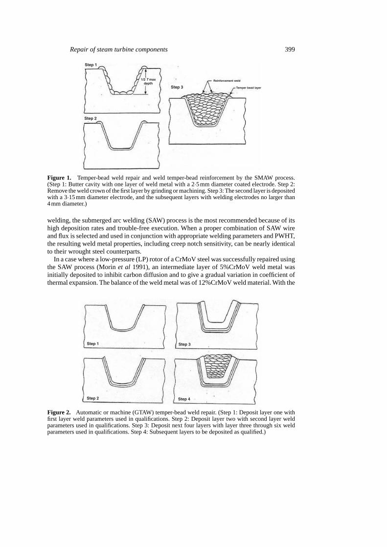
Figure 1. Temper-bead weld repair and weld temper-bead reinforcement by the SMAW process.(Step 1: Butter cavity with one layer of weld metal with a 2·5mm diameter coated electrode. Step 2:Remove the weld crown of the first layer by grinding or machining. Step 3: The second layer is depositedwith a 3·15mm diameter electrode, and the subsequent layers with welding electrodes no larger than4mm diameter.)
welding, the submerged arc welding (SAW) process is the most recommended because of itshigh deposition rates and trouble-free execution. When a proper combination of SAW wireand flux is selected and used in conjunction with appropriate welding parameters and PWHT,the resulting weld metal properties, including creep notch sensitivity, can be nearly identicalto their wrought steel counterparts.
In a case where a low-pressure (LP) rotor of a CrMoV steel was successfully repaired usingthe SAW process (Morinet al 1991), an intermediate layer of 5%CrMoV weld metal wasinitially deposited to inhibit carbon diffusion and to give a gradual variation in coefficient ofthermal expansion. The balance of the weld metal was of 12%CrMoV weld material. With the
Figure 2. Automatic or machine (GTAW) temper-bead weld repair. (Step 1: Deposit layer one withfirst layer weld parameters used in qualifications. Step 2: Deposit layer two with second layer weldparameters used in qualifications. Step 3: Deposit next four layers with layer three through six weldparameters used in qualifications. Step 4: Subsequent layers to be deposited as qualified.)
400 A K Bhaduri et al
resulting deposit the same creep rupture strength in the weld build-up deposit was achievedas in the original CrMoV material, in addition to substantial corrosion resistance and reducedsusceptibility to stress corrosion cracking. The tensile strength could also be adjusted over awide range by varying the heat treatment.
In another case, weld repair on the blade attachment of a high-pressure (HP) impulse wheelwas accomplished (Morinet al1991) using a similar procedure as in the preceding case. Here12%CrMoV was selected to achieve adequate high-temperature creep resistance as well ashigh high-temperature strength.As before, an intermediate layer of 5%CrMoV was applied tothe base metal in the area to be repair-welded, and then the 12%CrMoV was applied to coverthe 5%CrMoV. Gas turbine rotors that had a damage resulting from corrosion or mechanicalimpact were also repaired in this way (Morinet al1991).
4.2 Repair welding of cast steel casings
Cracks in the steam inlets of turbine casings made of CrMoV cast steel were successfullyrepair-welded using austenitic filler metals (Geissler 1992). Preheating at 423K was requiredwhen nickel-base ENiCr19Nb austenitic filler metal was used, while preheating was dispensedwith when iron-base 0.10%C–16Cr–25Ni–6Mo filler metal was used. The turbine operatedsatisfactorily after the repair.
Cracks in the casing of a pump turbine made of DIN 14315 standard cast material number1·0553 was also successfully repaired (Geissler 1992) using build-up welding under inductivepreheating at 423K using E515 B11020 (H) electrodes. This filler metal was selected on thebasis of its good toughness values. As a substitute for PWHT, which was not possible at site,three additional annealing passes were applied to the completely build-up weld which werelater ground away. The pump turbine was in operation for more than 15 years after it wasrepaired.
5. Repair welding of steam turbine components in nuclear power plants
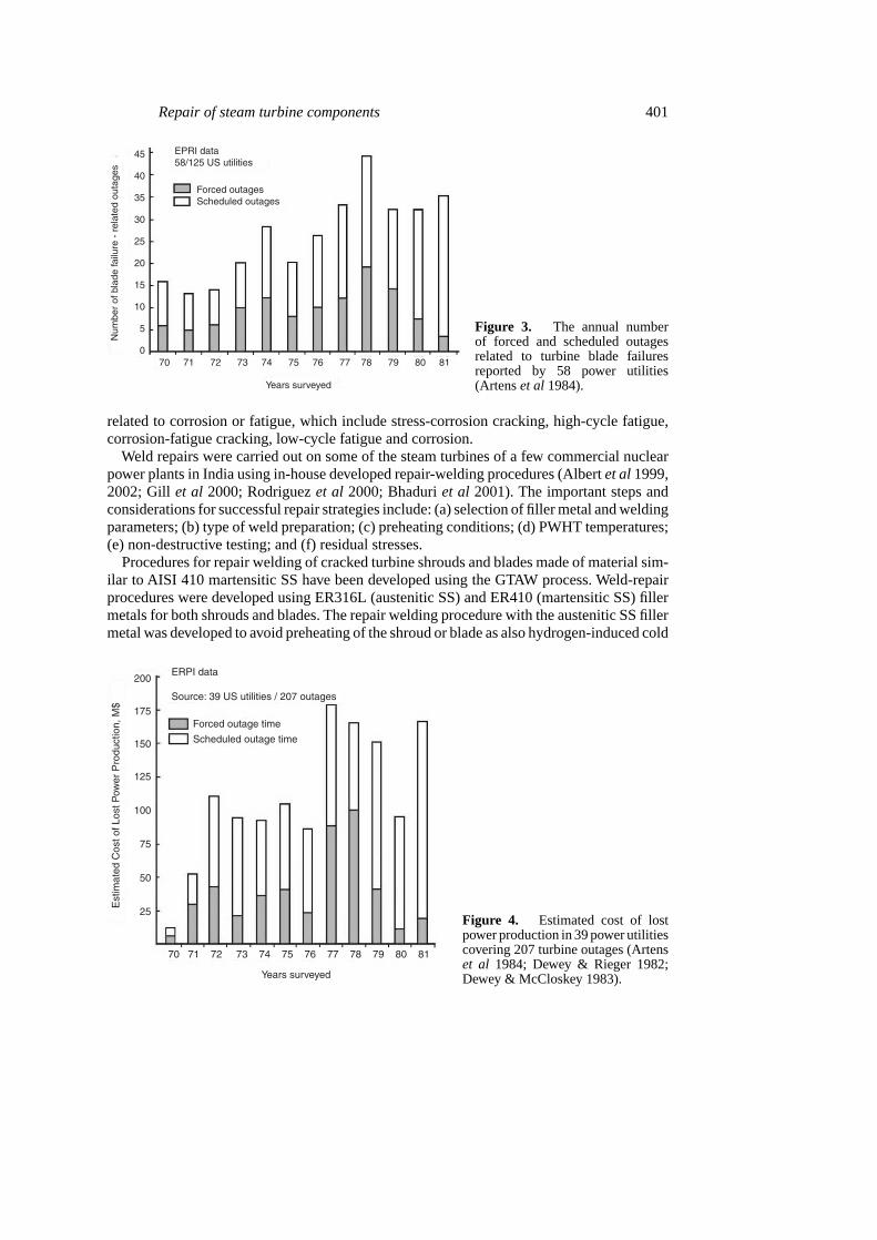
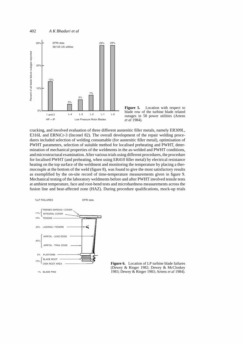
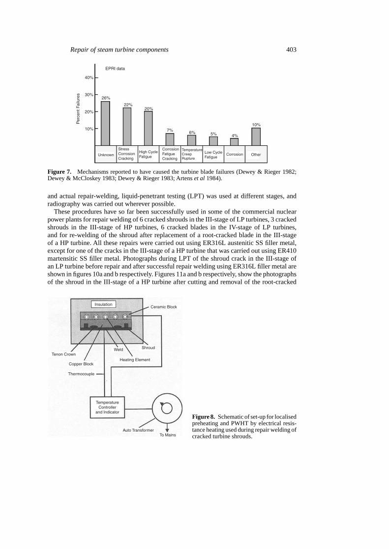
A steam turbine is the one of the most critical components in a power plant. As steam expandsthrough the turbine, its condition changes, requiring a spectrum of different blades betweenthe turbine inlet and exhaust. In this regard, the LP steam turbines are the most interestingwith the materials used belonging to the following alloy classes: Martensitic stainless steel(SS), precipitation-hardened (PH) SS, duplex SS and titanium alloys (e.g. Ti–6Al–4V). Themost popular alloy used for the blades is the 12Cr–1Mo–V martensitic SS (Artenset al1984).The failure statistics of blade-related turbine outages based on an Electrical Power ResearchInstitute (EPRI) of USA survey of power utilities between the years 1971 and 1981 (Dewey& McCloskey 1983;Artenset al1984; Dewey & Rieger 1982, 1983) is shown in figure 3. Theestimated cost of 207 of these turbine outages in terms of the lost power production is shownin figure 4, and it averaged $140 million annually during 1970 to 1981, or approximately$3·6 million for an “averaged” utility experiencing turbine problems (Artenset al1984). Thelocation of the turbine blades causing problems is given in figure 5, which shows that thereare problems associated with the first stages of the HP and the intermediate-pressure (IP)turbines and the last stages of the LP turbines. The LP turbine blade failure locations (figure 6)can be summarised as 46% occurring in the shroud and damping element, 40% in the airfoilregion and 14% in the blade attachment area. The mechanisms reported to have caused theturbine blade failures are shown in figure 7. This shows that over 50% of the incidents are
Repair of steam turbine components 401
Figure 3. The annual numberof forced and scheduled outagesrelated to turbine blade failuresreported by 58 power utilities(Artenset al1984).
related to corrosion or fatigue, which include stress-corrosion cracking, high-cycle fatigue,corrosion-fatigue cracking, low-cycle fatigue and corrosion.
Weld repairs were carried out on some of the steam turbines of a few commercial nuclearpower plants in India using in-house developed repair-welding procedures (Albertet al1999,2002; Gill et al 2000; Rodriguezet al 2000; Bhaduriet al 2001). The important steps andconsiderations for successful repair strategies include: (a) selection of filler metal and weldingparameters; (b) type of weld preparation; (c) preheating conditions; (d) PWHT temperatures;(e) non-destructive testing; and (f) residual stresses.
Procedures for repair welding of cracked turbine shrouds and blades made of material sim-ilar to AISI 410 martensitic SS have been developed using the GTAW process. Weld-repairprocedures were developed using ER316L (austenitic SS) and ER410 (martensitic SS) fillermetals for both shrouds and blades. The repair welding procedure with the austenitic SS fillermetal was developed to avoid preheating of the shroud or blade as also hydrogen-induced cold
Figure 4. Estimated cost of lostpower production in 39 power utilitiescovering 207 turbine outages (Artenset al 1984; Dewey & Rieger 1982;Dewey & McCloskey 1983).
402 A K Bhaduri et al
Figure 5. Location with respect toblade row of the turbine blade relatedoutages in 58 power utilities (Artenset al1984).
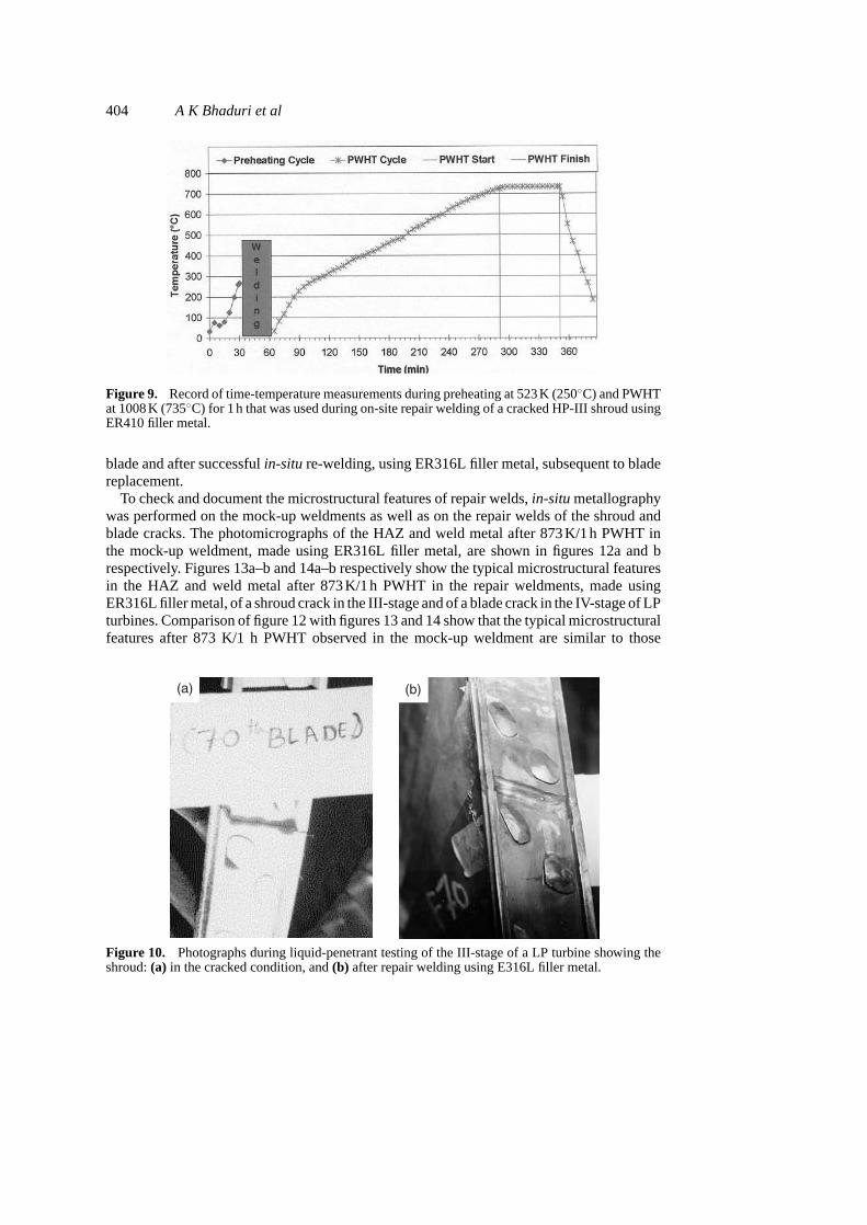
cracking, and involved evaluation of three different austenitic filler metals, namely ER309L,E316L and ERNiCr-3 (Inconel 82). The overall development of the repair welding proce-dures included selection of welding consumable (for austenitic filler metal), optimisation ofPWHT parameters, selection of suitable method for localised preheating and PWHT, deter-mination of mechanical properties of the weldments in the as-welded and PWHT conditions,and microstructural examination.After various trials using different procedures, the procedurefor localised PWHT (and preheating, when using ER410 filler metal) by electrical resistanceheating on the top surface of the weldment and monitoring the temperature by placing a ther-mocouple at the bottom of the weld (figure 8), was found to give the most satisfactory resultsas exemplified by the on-site record of time-temperature measurements given in figure 9.Mechanical testing of the laboratory weldments before and after PWHT involved tensile testsat ambient temperature, face and root-bend tests and microhardness measurements across thefusion line and heat-affected zone (HAZ). During procedure qualifications, mock-up trials
Figure 6. Location of LP turbine blade failures(Dewey & Rieger 1982; Dewey & McCloskey1983; Dewey & Rieger 1983; Artenset al1984).
Repair of steam turbine components 403
Figure 7. Mechanisms reported to have caused the turbine blade failures (Dewey & Rieger 1982;Dewey & McCloskey 1983; Dewey & Rieger 1983; Artenset al1984).
and actual repair-welding, liquid-penetrant testing (LPT) was used at different stages, andradiography was carried out wherever possible.
These procedures have so far been successfully used in some of the commercial nuclearpower plants for repair welding of 6 cracked shrouds in the III-stage of LP turbines, 3 crackedshrouds in the III-stage of HP turbines, 6 cracked blades in the IV-stage of LP turbines,and for re-welding of the shroud after replacement of a root-cracked blade in the III-stageof a HP turbine. All these repairs were carried out using ER316L austenitic SS filler metal,except for one of the cracks in the III-stage of a HP turbine that was carried out using ER410martensitic SS filler metal. Photographs during LPT of the shroud crack in the III-stage ofan LP turbine before repair and after successful repair welding using ER316L filler metal areshown in figures 10a and b respectively. Figures 11a and b respectively, show the photographsof the shroud in the III-stage of a HP turbine after cutting and removal of the root-cracked
Figure 8. Schematic of set-up for localisedpreheating and PWHT by electrical resis-tance heating used during repair welding ofcracked turbine shrouds.
404 A K Bhaduri et al
Figure 9. Record of time-temperature measurements during preheating at 523K (250◦C) and PWHTat 1008K (735◦C) for 1h that was used during on-site repair welding of a cracked HP-III shroud usingER410 filler metal.
blade and after successfulin-situ re-welding, using ER316L filler metal, subsequent to bladereplacement.
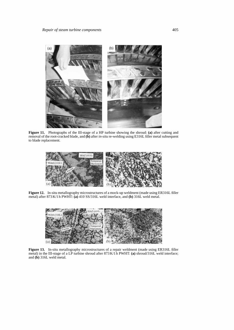
To check and document the microstructural features of repair welds,in-situmetallographywas performed on the mock-up weldments as well as on the repair welds of the shroud andblade cracks. The photomicrographs of the HAZ and weld metal after 873K/1h PWHT inthe mock-up weldment, made using ER316L filler metal, are shown in figures 12a and brespectively. Figures 13a–b and 14a–b respectively show the typical microstructural featuresin the HAZ and weld metal after 873K/1h PWHT in the repair weldments, made usingER316L filler metal, of a shroud crack in the III-stage and of a blade crack in the IV-stage of LPturbines. Comparison of figure 12 with figures 13 and 14 show that the typical microstructuralfeatures after 873 K/1 h PWHT observed in the mock-up weldment are similar to those
(a) (b)
Figure 10. Photographs during liquid-penetrant testing of the III-stage of a LP turbine showing theshroud:(a) in the cracked condition, and(b) after repair welding using E316L filler metal.
Repair of steam turbine components 405
(a) (b)
Figure 11. Photographs of the III-stage of a HP turbine showing the shroud:(a) after cutting andremoval of the root-cracked blade, and(b) afterin-siture-welding using E316L filler metal subsequentto blade replacement.
(a) (b)
Figure 12. In-situ metallography microstructures of a mock-up weldment (made using ER316L fillermetal) after 873K/1h PWHT:(a) 410 SS/316L weld interface, and(b) 316L weld metal.
(a) (b)
Figure 13. In-situ metallography microstructures of a repair weldment (made using ER316L fillermetal) in the III-stage of a LP turbine shroud after 873K/1h PWHT:(a) shroud/316L weld interface;and(b) 316L weld metal.
406 A K Bhaduri et al
(a) (b)
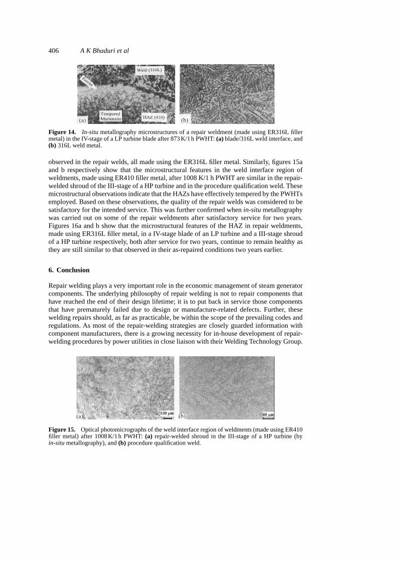
Figure 14. In-situ metallography microstructures of a repair weldment (made using ER316L fillermetal) in the IV-stage of a LP turbine blade after 873K/1h PWHT:(a) blade/316L weld interface, and(b) 316L weld metal.
observed in the repair welds, all made using the ER316L filler metal. Similarly, figures 15aand b respectively show that the microstructural features in the weld interface region ofweldments, made using ER410 filler metal, after 1008 K/1 h PWHT are similar in the repair-welded shroud of the III-stage of a HP turbine and in the procedure qualification weld. Thesemicrostructural observations indicate that the HAZs have effectively tempered by the PWHTsemployed. Based on these observations, the quality of the repair welds was considered to besatisfactory for the intended service. This was further confirmed whenin-situmetallographywas carried out on some of the repair weldments after satisfactory service for two years.Figures 16a and b show that the microstructural features of the HAZ in repair weldments,made using ER316L filler metal, in a IV-stage blade of an LP turbine and a III-stage shroudof a HP turbine respectively, both after service for two years, continue to remain healthy asthey are still similar to that observed in their as-repaired conditions two years earlier.
6. Conclusion
Repair welding plays a very important role in the economic management of steam generatorcomponents. The underlying philosophy of repair welding is not to repair components thathave reached the end of their design lifetime; it is to put back in service those componentsthat have prematurely failed due to design or manufacture-related defects. Further, thesewelding repairs should, as far as practicable, be within the scope of the prevailing codes andregulations. As most of the repair-welding strategies are closely guarded information withcomponent manufacturers, there is a growing necessity for in-house development of repair-welding procedures by power utilities in close liaison with their Welding Technology Group.
(a) (b)
Figure 15. Optical photomicrographs of the weld interface region of weldments (made using ER410filler metal) after 1008K/1h PWHT:(a) repair-welded shroud in the III-stage of a HP turbine (byin-situmetallography), and(b) procedure qualification weld.
Repair of steam turbine components 407
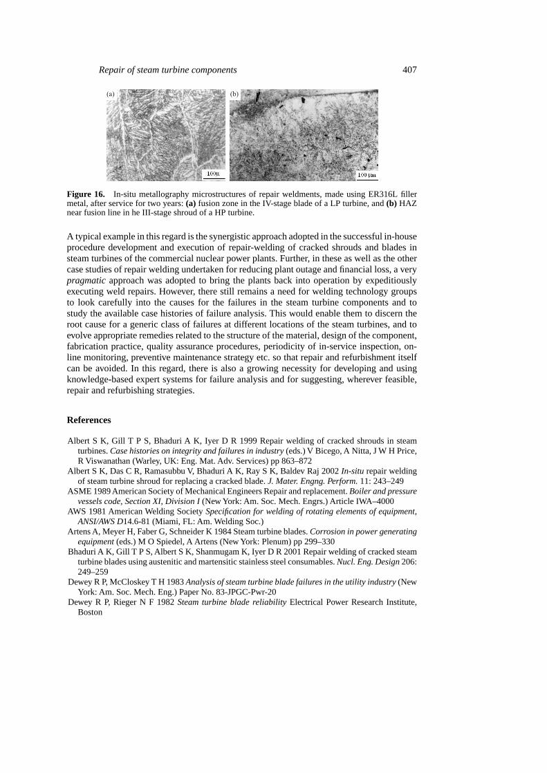
Figure 16. In-situ metallography microstructures of repair weldments, made using ER316L fillermetal, after service for two years:(a) fusion zone in the IV-stage blade of a LP turbine, and(b) HAZnear fusion line in he III-stage shroud of a HP turbine.
A typical example in this regard is the synergistic approach adopted in the successful in-houseprocedure development and execution of repair-welding of cracked shrouds and blades insteam turbines of the commercial nuclear power plants. Further, in these as well as the othercase studies of repair welding undertaken for reducing plant outage and financial loss, a verypragmaticapproach was adopted to bring the plants back into operation by expeditiouslyexecuting weld repairs. However, there still remains a need for welding technology groupsto look carefully into the causes for the failures in the steam turbine components and tostudy the available case histories of failure analysis. This would enable them to discern theroot cause for a generic class of failures at different locations of the steam turbines, and toevolve appropriate remedies related to the structure of the material, design of the component,fabrication practice, quality assurance procedures, periodicity of in-service inspection, on-line monitoring, preventive maintenance strategy etc. so that repair and refurbishment itselfcan be avoided. In this regard, there is also a growing necessity for developing and usingknowledge-based expert systems for failure analysis and for suggesting, wherever feasible,repair and refurbishing strategies.
References
Albert S K, Gill T P S, Bhaduri A K, Iyer D R 1999 Repair welding of cracked shrouds in steamturbines.Case histories on integrity and failures in industry(eds.) V Bicego, A Nitta, J W H Price,R Viswanathan (Warley, UK: Eng. Mat. Adv. Services) pp 863–872
Albert S K, Das C R, Ramasubbu V, Bhaduri A K, Ray S K, Baldev Raj 2002In-situ repair weldingof steam turbine shroud for replacing a cracked blade.J. Mater. Engng. Perform.11: 243–249
ASME 1989 American Society of Mechanical Engineers Repair and replacement.Boiler and pressurevessels code, Section XI, Division I(New York: Am. Soc. Mech. Engrs.) Article IWA–4000
AWS 1981 American Welding SocietySpecification for welding of rotating elements of equipment,ANSI/AWS D14.6-81 (Miami, FL: Am. Welding Soc.)
Artens A, Meyer H, Faber G, Schneider K 1984 Steam turbine blades.Corrosion in power generatingequipment(eds.) M O Spiedel, A Artens (New York: Plenum) pp 299–330
Bhaduri A K, Gill T P S, Albert S K, Shanmugam K, Iyer D R 2001 Repair welding of cracked steamturbine blades using austenitic and martensitic stainless steel consumables.Nucl. Eng. Design206:249–259
Dewey R P, McCloskey T H 1983Analysis of steam turbine blade failures in the utility industry(NewYork: Am. Soc. Mech. Eng.) Paper No. 83-JPGC-Pwr-20
Dewey R P, Rieger N F 1982Steam turbine blade reliabilityElectrical Power Research Institute,Boston

408 A K Bhaduri et al
Dewey R P, Rieger N F 1983 Report no. RP 1856-1, Electrical Power Research Institute, BostonGeissler K 1992 Repair welding on cast steel casings in power stations in East Germany Report no.
XI-587-92, International Institute of WeldingGill T P S, Bhaduri A K, Albert S K, Ramasubbu V, Srinivasan G, Shanmugam K, Balachander K
2000 Repair welding of cracked steam turbine shrouds using matching composition consumable.Materials ageing and life management(eds.) Baldev Raj, K B S Rao, T Jayakumar, R K Dayal(Chennai: Allied Publishers) pp 1467–1477
Gnirss G 1992 Repair Welding, Report no. XI-585-92, International Institute of Welding, ParisHedden O F, McDonald M S 1991ASME Section Eleven perspective.Maintenance and repair welding
in power plants(Miami, FL: Am. Welding Soc.) pp 342–348Hermann R A 1991 NRC perspective on codes and regulations.Maintenance and repair welding in
power plants(Miami, FL: Am. Welding Soc.) pp 339–341Malin V, Fields S F 1992 A balanced approach to repair of large structures by welding.Welding J.71:
63–72Mathews A W 1991 National Board – Accreditation programs.Maintenance and repair welding in
power plants(Miami, FL: Am. Welding Soc.) pp 348–355Morin M D, Faber G, Kuhnen G 1991 Weld build-up repairs of turbine rotors.Maintenance and repair
welding in power plants(Miami, FL: Am. Welding Soc.) pp 288–301Rodriguez P, Bhaduri A K, GillT P S 2000 Role of repair welding in life management of power plant
components.Proc Int. Symp. on Joining of Materials(Tiruchirapalli: Welding Res. Inst.) pp 12–23