Embed Size (px)
Citation preview

1
Recent Publicity
http://www.postandcourier.com/business/it-s-on-his-radar-charleston-professor-
sees-new-use/article_ea87e2c2-041e-11e7-a259-4f5af69727dd.html http://www.charlestonbusinessmag.com/archives/1285

THE CITADEL, THE MILITARY COLLEGE OF SOUTH CAROLINA
171 Moultrie Street, Charleston, SC 29409
Nonlinear Radar for Remotely Finding
and Identifying Handheld Electronics
Anthony F. Martone, Kyle A. Gallagher
U.S. Army Research Laboratory
Adelphi, MD 20783
Ram M. Narayanan
Pennsylvania State University
University Park, PA 16802
Gregory J. Mazzaro
The Citadel, The Military College of South Carolina
Charleston, SC 29409
17-Apr-2017
3
Presentation Overview
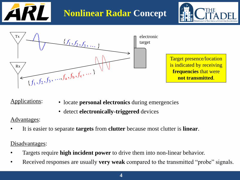
• Introduction to Nonlinear Radar
• Concept, Motivations
• Electromagnetic Nonlinearity, Harmonics
• Nonlinear Radar Research
• Harmonic Radar, for Detecting Electronics
• Stepped-Frequency, for Ranging
• Experiments, Results
• Recent Patents
• Future Work
United States
Army Research Laboratory
Synchronous Impulse
Reconstruction Radar
4
Nonlinear Radar Concept
Applications:
Advantages:
• It is easier to separate targets from clutter because most clutter is linear.
Disadvantages:
• Targets require high incident power to drive them into non-linear behavior.
• Received responses are usually very weak compared to the transmitted “probe” signals.
Target presence/location
is indicated by receiving
frequencies that were
not transmitted.
Tx
Rx
• locate personal electronics during emergencies
• detect electronically-triggered devices
electronic
target

5
Sources of Nonlinearity
+
_ +
_
Active elements & components – by design; above system noise floor
Passive elements & components – unintended; below system noise floor
diodes transistors amplifiers mixers
f1
f2
f1 + f2
contacts [1,2]
metal 1
metal 2
oxide
metal
thermal
effects [5] connectors [3]
V R
ferro-electrics [4]
Nearly all electronics are nonlinear, to some degree.

6
Temperature-Dependent
Resistance
Vin R
Iout
voltage applied,
current flows
resistor
heats up
resistance
increases current
decreases
resistor cools
down resistance
decreases
current
increases
input: constant
output: sinusoidal
nonlinear
Vin
time
Iout R
time time

Tx
Rx
7
Nonlinear Radar Research
We view each target as
a collection of RF
nonlinearities.
Ein
Erefl... LNA
BPF
one possible
signal path:

8
Nonlinear Radar Research
Tx
Rx
• Which frequencies and waveforms are best to transmit?
• What is the minimum transmit power required for detection?
• Which is the best antenna design (gain, polarization, etc.) for detection and ranging?
• How should the transmitter be designed to achieve high linearity?
• How should the receiver be designed to achieve high sensitivity?
• How should a signal processor be designed to recognize familiar targets?
This type of
radar research
is in its infancy.

9
Harmonic Radar: Theory
2 3
o u t 1 in 2 in 3 in. . .E a E a E a E
Let the nonlinearity
be approximated by
a power series [6]
Let the input waveform be a sinusoid: in 0 0cosE E t
Then the device response (output) is
2
o u t 1 0 0 2 0 0
3
3 0 0
c o s c o s
c o s ...
E a E t a E t
a E t
o u t 1 0 0
2
2 0 0
3
3 0 0
c o s
2 c o s 2
4 c o s 3 ...
E a E t
a E t
a E t
harmonics
input
output
input = { f }
output = { f, 2f, 3f, 4f, 5f, 6f, … }

10
intermodulation
difference / “beat”
frequencies
harmonics
1
2
9 9 M H z
1 0 1 M H z
f
f
1
2
9 9 M H z
1 0 1 M H z
f
f
input
output
In the frequency domain, nonlinearity
appears as spurious spectral content
(e.g. harmonics, intermodulation).
Intermodulation Radar:
Theory

11
Prior (Published) Work
[8]
[7]
RADAR TAGS for INSECT TRACKING
[9]
• simulations show detection possible > 22 m at 80 GHz
AUTOMOTIVE RADAR for detecting
“VULNERABLE ROAD USERS”
MILITARY RADAR for detecting
MANMADE METALLIC OBJECTS
[10]
NLR for detecting handheld
electronics is novel.

12
Presentation Overview
• Introduction to Nonlinear Radar
• Concept, Motivations
• Electromagnetic Nonlinearity, Harmonics
• Nonlinear Radar Research
• Harmonic Radar, for Detecting Electronics
• Stepped-Frequency, for Ranging
• Experiments, Results
• Recent Patents
• Future Work
United States
Army Research Laboratory
Synchronous Impulse
Reconstruction Radar
13
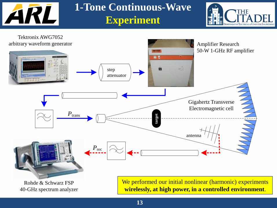
1-Tone Continuous-Wave
Experiment
step
attenuator
Ptrans
targ
et
antenna
Prec
Tektronix AWG7052
arbitrary waveform generator Amplifier Research
50-W 1-GHz RF amplifier
Rohde & Schwarz FSP
40-GHz spectrum analyzer
Gigahertz Transverse
Electromagnetic cell
We performed our initial nonlinear (harmonic) experiments
wirelessly, at high power, in a controlled environment.

14
GTEM cell, outside, front GTEM cell, outside, back
Gigahertz Transverse
Electromagnetic cell
VTx
1-Tone Continuous-Wave
Experiment
A GTEM cell is essentially
a large, flared waveguide.
[11]

15
target placement GTEM cell, inside
antenna, absorber
VTx
VTx
1-Tone Continuous-Wave
Experiment
A GTEM cell is essentially
a large, flared waveguide. Gigahertz Transverse
Electromagnetic cell

16
Tx band Rx band
~36 dB
gain
~50 dB
gain
The transmitter amplifies each tone
by >3 orders of magnitude to send
2 Watts to the transmit antenna.
The receiver amplifies each
received harmonic received by
~5 orders of magnitude.
Radar Transmitter:
In-House Filter Design
[12]
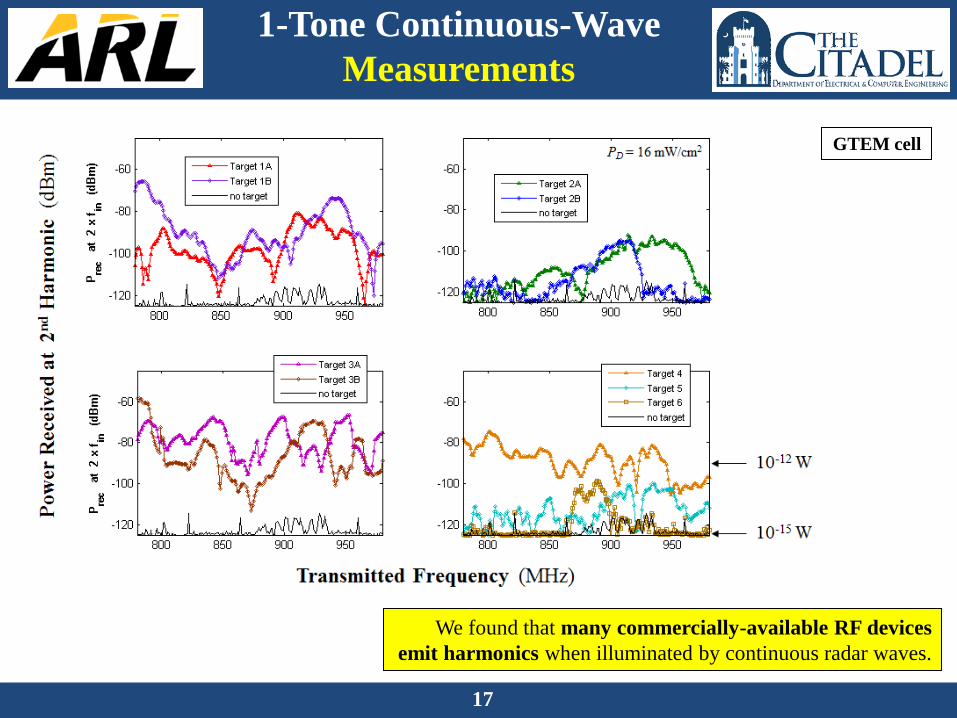
17
1-Tone Continuous-Wave
Measurements
We found that many commercially-available RF devices
emit harmonics when illuminated by continuous radar waves.
GTEM cell

18
Nonlinear
Stepped-Frequency Radar
A1
f1
A2
f2
A3
f3
A4
f4
A5
f5
2f0 2f0 + 2Df 2f0 + 4Df 2f0 + 6Df 2f0 + 8Df
amplitude
phase
frequency
…
…
…
…
IFFT
2
cR t
Tra
nsm
itte
d
Rec
eived
P
roce
ssed
After constructing H() of the
environment, an inverse FFT
gives its impulse response.

19
12 ft
quad-ridge
horn antenna
target location
( all targets were place
with antennas oriented
vertically )
Nonlinear Step-Freq Radar:
Experiment
We set up our antenna and targets in a low-metal-content
environment at ARL’s Adelphi Laboratory Center.

20
arbitrary
waveform
generator
20GS/s
oscilloscope
triple-voltage
power
supplies
power
amplifier
Nonlinear Step-Freq Radar:
Experiment
to scope
from power
amplifier
to scope
to/from
antenna directional
coupler
low-noise
amps x3 diplexers
x2
Most of the prototype radar parts
were commercial off-the-shelf
components or standard radio-
frequency laboratory instruments.
Data capture and processing were
performed on a laptop, in Matlab.
[13]

21
Range [ft]
Dopple
r speed [
m/s
]
Nonlinear Moving Target
-10 0 10 20 30 40-1.5
-1
-0.5
0
0.5
1
-40
-35
-30
-25
-20
-15
-10
-5
0
Rec
eiv
ed P
ow
er
(dB
sm,
no
rmal
ized
)
One of the targets was
placed on a moving
platform.
During data capture,
the target moved
towards the radar.
UWB Harmonic Radar:
Moving-Target Results
[14]
22
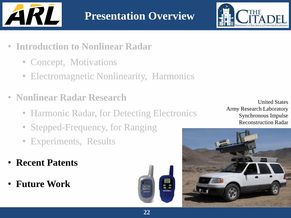
Presentation Overview
• Introduction to Nonlinear Radar
• Concept, Motivations
• Electromagnetic Nonlinearity, Harmonics
• Nonlinear Radar Research
• Harmonic Radar, for Detecting Electronics
• Stepped-Frequency, for Ranging
• Experiments, Results
• Recent Patents
• Future Work
United States
Army Research Laboratory
Synchronous Impulse
Reconstruction Radar

23
US patent # 9,395,434
“Multitone Harmonic Radar and Method of Use”

24
US patent # 9,435,882
“Method and Apparatus for Cognitive Nonlinear Radar”

25
US patent # 9,476,973
“Combined Radar Assembly with Linear and Nonlinear Radar”

26
Range [ft]
Dopple
r speed [
m/s
]
Nonlinear Moving Target
-10 0 10 20 30 40-1.5
-1
-0.5
0
0.5
1
-40
-35
-30
-25
-20
-15
-10
-5
0
Nonlinear Radar Research:
To-Date & Future
Tx
Rx
We have (a) shown that RF electronics emit harmonics when illuminated by radar waves,
which enables detection of these targets
(b) developed an experimental prototype of a stepped-frequency harmonic radar,
which is able to detect & locate commercially-available RF electronic devices, and
(c) published and patented novel radar hardware designs
to disseminate & protect our research.
We intend to (d) package the radar onto a mobile platform (vehicle), and
(e) develop signal-processing techniques to identify particular targets.

27
References
[1] C. Vicente and H. L. Hartnagel, “Passive-intermodulation analysis between rough rectangular waveguide flanges,” IEEE Transactions on
Microwave Theory and Techniques, Vol. 53, No. 8, Aug. 2005, pp. 2515–2525.
[2] H. Huan and F. Wen-Bin, “On passive intermodulation at microwave frequencies,” in Proceedings of the Asia-Pacific Electromagnetic
Conference, Nov. 2003, pp. 422–425.
[3] J. Henrie, A. Christianson, and W. J. Chappell, “Prediction of passive intermodulation from coaxial connectors in microwave networks,”
IEEE Transactions on Microwave Theory and Techniques, Vol. 56, No. 1, Jan. 2008.
[4] G. C. Bailey and A. C. Ehrlich, “A study of RF nonlinearities in nickel,” Journal of Applied Physics, Vol. 50, No. 1, Jan. 1979, pp. 453-461.
[5] J. R. Wilkerson, K. G. Gard, A. G. Schuchinsky, and M. B. Steer, “Electro-thermal theory of intermodulation distortion in lossy microwave
components,” IEEE Transactions on Microwave Theory and Techniques, Vol. 56, No. 12, Dec. 2008.
[6] J. C. Pedro and N. B. Carvalho, Intermodulation Distortion in Microwave and Wireless Circuits. Boston, MA: Artech House, 2003.
[7] N. Tahir and G. Brooker, “Recent developments and recommendations for improving harmonic radar tracking systems,” in Proceedings of
the 5th European Conference on Antennas and Propagation, Apr. 2011, pp. 1531–1535.
[8] D. Psychoudakis, W. Moulder, C. C. Chen, H. Zhu, and J. L. Volakis, “A portable low-power harmonic radar system and conformal tag for
insect tracking”, IEEE Antennas and Wireless Propagation Letters, Vol. 7, 2008, pp. 444–447.
[9] J. Saebboe, V. Viikari, T. Varpula, and H. Seppa, “Harmonic automotive radar for VRU classification”, in Proceedings of the International
Radar Conference: Surveillance for a Safer World, Oct. 2009, pp. 1–5.
[10] C. L. Opitz, “Radar object detector using non-linearities,” U. S. Patent 4,053,891, Oct. 11, 1977.
[11] G. J. Mazzaro and A. F. Martone, “Harmonic and multitone radar: Theory and experimental apparatus,” U.S. Army Research Laboratory
Technical Report, No. 6235, Oct. 2012.
[12] K. A. Gallagher, G. J. Mazzaro, A. F. Martone, K. D. Sherbondy, and R. M. Narayanan, “Filter selection for a harmonic radar receiver,”
accepted to SPIE Defense, Security, & Sensing 2015, Baltimore, MD, April 2015.
[13] G. J. Mazzaro, K. A. Gallagher, A. R. Owens, K. D. Sherbondy, and R. M. Narayanan, “Ultra-Wideband Harmonic Radar for Locating
Radio-Frequency Electronics,” U.S. Army Research Laboratory Technical Report, No. 7256, Mar. 2015.
[14] K. A. Gallagher, R. M. Narayanan, G. J. Mazzaro, K. I. Ranney, A. F. Martone, and K. D. Sherbondy, “Moving Target Indication with
Non-Linear Radar,” Proceedings of the IEEE Radar Conference, pp. 1428-1433, May 2015.