Embed Size (px)
Citation preview
UCSDDEPARTMENT OF COMPUTER SCIENCE
CS 123a Computer Networks: Physical Layer Lectures
In the first two lectures, we finished our overview of networks. Now we move bottom up throughthe layers, starting with the physical layer. Recall that the physical layer is the actual transmissionmedium for bits, usually through some form of wire. In the Hazel’s hats analogy it corresponds tothe type of plane or the form of balloon used to transport mail. The Data Link layer correspondsto the specific carrier on each hop – i.e., VARIG Airlines, CASABLANCA Balloon etc.
We will roughly use 3-4 lectures for each layer.
1 What is the Physical Layer
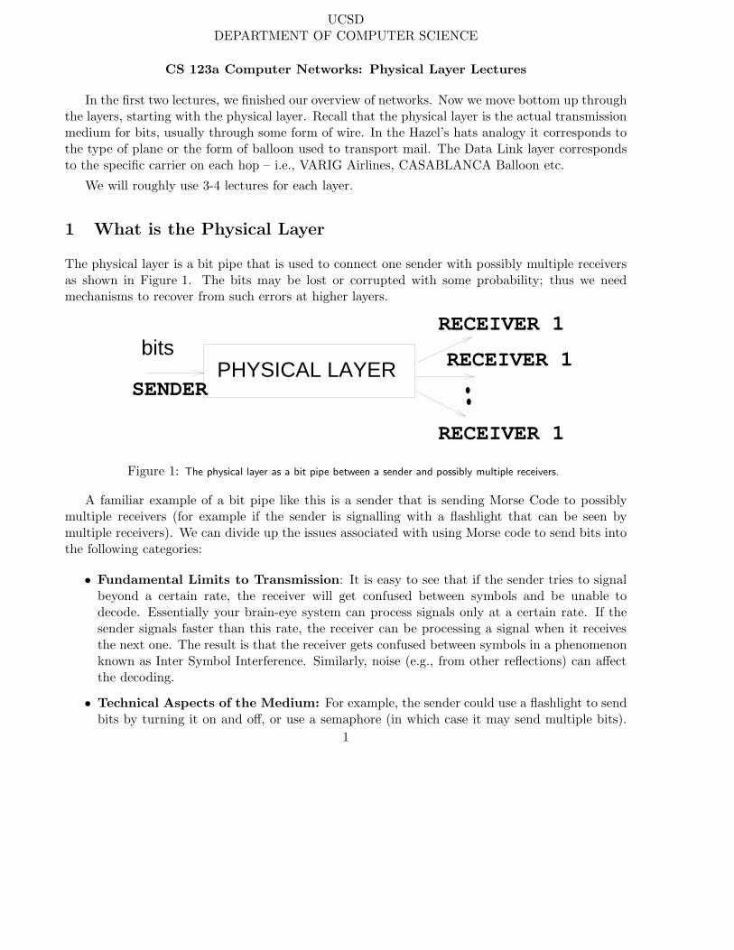
The physical layer is a bit pipe that is used to connect one sender with possibly multiple receiversas shown in Figure 1. The bits may be lost or corrupted with some probability; thus we needmechanisms to recover from such errors at higher layers.
SENDER
RECEIVER 1
RECEIVER 1
RECEIVER 1
bitsPHYSICAL LAYER
Figure 1: The physical layer as a bit pipe between a sender and possibly multiple receivers.
A familiar example of a bit pipe like this is a sender that is sending Morse Code to possiblymultiple receivers (for example if the sender is signalling with a flashlight that can be seen bymultiple receivers). We can divide up the issues associated with using Morse code to send bits intothe following categories:
• Fundamental Limits to Transmission: It is easy to see that if the sender tries to signalbeyond a certain rate, the receiver will get confused between symbols and be unable todecode. Essentially your brain-eye system can process signals only at a certain rate. If thesender signals faster than this rate, the receiver can be processing a signal when it receivesthe next one. The result is that the receiver gets confused between symbols in a phenomenonknown as Inter Symbol Interference. Similarly, noise (e.g., from other reflections) can affectthe decoding.
• Technical Aspects of the Medium: For example, the sender could use a flashlight to sendbits by turning it on and off, or use a semaphore (in which case it may send multiple bits).
1
The technical aspects of the particular medium do matter (e.g., flashlight battery lifetime,ability to see semaphores at night etc.)
• Encoding and Decoding Information: Encoding in Morse code consists of using a codeto send characters. Unlike ASCII, it is a variable length code. However, decoding is moretricky. A long series of dashes could be interpreted as twice the number of dashes if thereceiver thinks the sender is going twice as fast. In Morse code, the receiver has to know orlearn how fast the sender is going in order to recover the sender bits. This is the problem of“clock recovery”; after knowing at what rate the sender is sending, the receiver can interpretthe received signal and decode it. Morse code can have a simple clock recovery scheme ifthe receiver and sender have agreed beforehand on the rate and they both have accuratestopwatches. However, there is still the problem of starting correctly (getting in phase).The problem gets worse in high speed communications when the stopwatches of sender andreceiver drift over time.
2 Physical Layer Sublayers
As with the Morse code example above, we divide up the problem of the physical layer into threesublayers. Each sublayer deals with an independent problem and has independent issues. Thisallows us to separate our concerns.
The sublayers correspond to the Morse code example above:
• Transmission Sublayer: The bottom sublayer describes the essential properties of the media(e.g., frequency response, bit error rate) that influence and limit transmission rates. This canbe studied almost independently of the particular kind of media used.
• Media Dependent Sublayer: The middle sublayer describes properties of particular media —e.g.. satellites, coaxial cable, fiber. The particular properties do influence protocols and areworth knowing. For example, satellites have a large propagation delay and this necessitatesdifferent protocols.
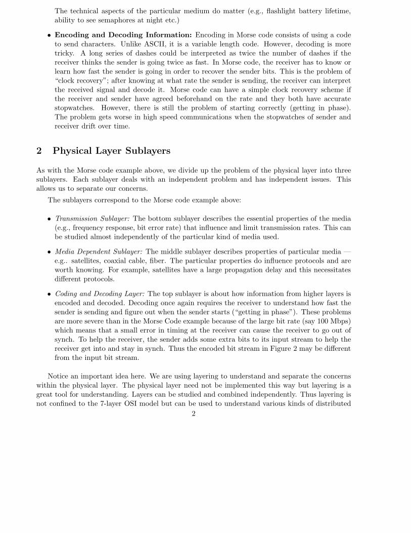
• Coding and Decoding Layer: The top sublayer is about how information from higher layers isencoded and decoded. Decoding once again requires the receiver to understand how fast thesender is sending and figure out when the sender starts (“getting in phase”). These problemsare more severe than in the Morse Code example because of the large bit rate (say 100 Mbps)which means that a small error in timing at the receiver can cause the receiver to go out ofsynch. To help the receiver, the sender adds some extra bits to its input stream to help thereceiver get into and stay in synch. Thus the encoded bit stream in Figure 2 may be differentfrom the input bit stream.
Notice an important idea here. We are using layering to understand and separate the concernswithin the physical layer. The physical layer need not be implemented this way but layering is agreat tool for understanding. Layers can be studied and combined independently. Thus layering isnot confined to the 7-layer OSI model but can be used to understand various kinds of distributed
2
PHYSICAL LAYER: SUBLAYERS
Sublayer
Coding Sublayer
Sublayer
Input Signal Output Signal
Media Transmission Media Reception
Decoding Sublayer
01010000 01010000
Input Stream Output Stream
Coded Stream Coded Stream
(SHANNON AND NYQUIST LIMITS)
Signal Transmission Sublayer
Figure 2: Physical Layer Sublayers
systems. We will use sublayering again to understand the Data Link, Routing and other layers inlater parts of the course.
3 Organization of Rest of Chapter
The organization of the rest of the chapter is as follows. We will study the sublayers of the physicallayer roughly bottom up. We will start with the fundamental transmission sublayer which talksabout the basic issues of sending signals and bits over physical channels and the limits to themaximum bit rate we can achieve. Next, we will talk about the topmost sublayer: the clockrecovery sublayer and show how we encode bits to force transitions that help the receiver do clockrecovery. Finally, we talk about the specific types of media (i.e., fiber, satellites, etc) and how eachof them have their advantages and disadvantages.
In terms of our Hazel’s hats analogy, the transmission sublayer talks about some fundamentallaws of communication (e.g., Shannon limit) which is analogous to Newton’s laws of motion thataffects all forms of vehicular transport. The media dependent sublayer is analogous to the issues
3
in choosing between, say, a balloon, a train or a plane. Note that a balloon may be good to reacha hilly unreachable area but a plane is faster; similarly, low speed radio links may be good forunreachable areas which have no access to wires but a fiber link is faster. Finally, the encodinglayer is analogous to the various methods one could use to correctly unload parcels that are placedon a given carrier.
4 Transmission Sublayer
If we look back at Figure 1 we see that the goal of the physical layer is to send a sequence of 0’s and1’s from a sender to a receiver. Since the receiver is far away from the sender and they do not havea common memory, how can we send the bits stored in the sender’s memory to the receiver? Themost common way is by sending energy (e.g., light, electricity) over a channel (e.g., fiber, cable).There are many ways to code bits using energy (e.g., we can sing high to encode a 1, sing low toencode a 0). For the next few sections we will consider the simplest coding scheme called On-offcoding. Thus we code a 0 by sending no energy down the channel during a bit time; we code a 1by sending energy down the channel. Our flashlight is an example where we send a 1 by turninglight on. However we have the following
Problem: Real channels distort input energy signals. The ouput signal is not the same as theinput signal. This leads to two immediate questions.
• Q1: How can we predict what a given channel will do to an input signal given some propertiesof the channel? We will show how to do this using a tool called Fourier Analysis.
• Q2: How does distortion affect maximum bit rate? We will show that the inherent inertia(i.e., sluggishness) of the channel affects the maximum signalling rate (Nyquist limit) and theinertia plus noise affects the maximum bit rate (Shannon limit).
These are the issues we cover in this section. Thus the rest of this section will have 4 subsections:first we talk about signals and channels, then we talk about Fourier analysis, then about the Nyquistlimit and finally we finish with the Shannon limit.
4.0.1 Signals and Channels
A signal is something that carries a measurable amount of energy that varies with time. This couldbe a light signal, a sound signal, or an electric signal. The easiest way to draw a signal is to drawa graph of how the energy varies with time. The magnitude of the energy is called the amplitudeand we plot it on the y-axis while time is shown on the x-axis. For electricity, we might measureamplitude in volts; for sound in decibels, for light in terms of light intensity.
It is convenient to divide signals into the following categories: a continuous signal is one in whichthe signal graph is continuous (no sudden jumps, can take on an in infinite number of continuousvalues) while a discrete signal is one in which there are only a discrete number of values and thesignal may exhibit sudden jumps. Thus a square wave is discrete while a sine wave is continuous.
4

Typically input signals are close to discrete while output signals (after channel distortion) arecontinuous.
An important subclass of signals are periodic signals. These are signals that repeat their shapeafter a finite amount of time called their period, often denoted by T . The frequency of the periodicsignal is the number of repetitions per second. If T is measured in seconds f = 1/T . Frequencyis measured in Hertz. Thus a signal that repeats itself twice a second has a frequency of two Hz.Refer to your slides for pictures of these concepts.
Real bit streams do not normally form periodic signals. Clearly a random sequence of bits willbe aperiodic (or its not random!). However, if you sent 010101... you would get a periodic signal.It turns out to be convenient for the analysis, however, to rewrite the effect of each bit in terms ofthe sum of a number of periodic signals, the so-called sine waves (more later on Fourier Analysis).
The mathematical way to write a sine wave is A sin(2πft + θ). The value A is the maximumvalue of the amplitude. The value of θ is the initial phase shift, while f is the frequency and tis time. If you haven’t played around with sine waves, do so using a calculator. However, whentaking sines, remember that the angle in the formula is in radians, not in degrees. For example,suppose the frequency is 1 Hz. and θ is zero. Then at t = 0, the angle is 0 radians, and the valueof the wave is 0. At t = 1/4, the value of the angle is π/2 radians, and the signal has its maximumvalue of A. At t = 1/2, the value is 0 again; at t = 3/4 it is −A; at t = 1, it is 0 again, and thesignal repeats itself. If θ is say π/2, then the graph has the same shape, but it shifts to the left byπ/2 radians, which we call a phase shift.
The bottom line is that we study periodic sine waves because they help us find out what happensto arbitrary input signals placed on channels. So what are channels?
A channel is a physical medium that conveys energy from a sender to a receiver (e.g., a fiberlink for light, a copper wire for electricity). Of course the output signal typically distorts the inputsignal. So we need to understand what a given channel will to do to a particular input signal usingFourier Analysis.
4.1 Fourier Analysis
Here is the big picture:
• If we forget about noise, most channels are “nice” to sine waves. A sine wave of frequency fis always scaled by a fixed factor s(f) and phase shifted by a fixed amount p(f) regardless ofamplitude or time.
• Thus we can completely describe a channel by plotting the values of s(f) (frequency response)and p(f) (phase response) for all values of frequency f .
• To find what happens to arbitrary signal S, we i) Use Fourier Analysis to rewrite S as a sumof sine waves of different frequencies ii) Use frequency and phase response to see effect ofeach sine wave iii) Add scaled sine waves to find output signal using inverse Fourier analysis.
The fact that most real channels do not significantly distort sine waves (except for scaling andshifting) is quite a wonderful thing. This can be expressed more deeply by saying that sine waves
5

are eigen functions of Linear Time Invariant (LTI) systems and most real channels are close to LTIsystems. However, the fact remains a miracle that the extra mathematics does not really explain.It just is a fact that is true. Like gravity.
However, this means that we can completely characterize a channel by doing an experimentwhere send in a large number of sine waves of different frequencies and observe the resulting scalingand shift. This can be used to plot a frequency and phase response. An example is given inFigure 3. The figure shows that the channel basically scales all frequencies between 200 and 1200Hz by a factor of 2, and does not pass through (i.e., scales down to 0) all other frequencies.1
Scaling Factor
Frequency(Hz)
2
Frequency(Hz)
200 Hz
Phase Shift
90
180
100
FREQUENCYRESPONSE
PHASERESPONSE
200 Hz 1200 Hz
Figure 3: Example of Phase and Frequency Response
This figure shows that the channel is a band pass filter — i.e., it only passes through a narrowband of frequencies. The bandwidth of the channel is the width of its pass band, in this case 1000Hz. Most real channels have a much less clearly defined band region (instead of vertical linesdelineating a band you have a curved fall off) and one has to define the band in some arbitraryway (e.g., the range of frequencies for which the scale factor is within 80 percent of the maximumscale factor).
Most real channels will not pass through frequencies beyond a certain cutoff point. So whathappens if the input signal has a frequency greater than this cutoff frequency? For example, supposethe channel does not pass through frequencies greater than 1200 Hz and we send the sequence of
1Many speakers and other sound equipment will show similar curves to show their fidelity over a range of frequen-cies; bad speakers have a poor range and will tend to distort sounds of high pitch.
6
bits 000000... at the rate of say 3000 bits per second. The bit sequence creates a periodic signal of3000 Hz which the channel cannot pass through. The result is that the output will be significantlydistorted.
In effect, most channels are sluggish (they take time to respond to sudden changes) becausethey turn a deaf ear to higher frequencies in the input signal. Thus lower bandwidth channels aremore sluggish. This can easily be seen by Fourier Analysis.
In your slides (PhyExtraSlides) we showed what happens to a square wave of frequency f aswe gradually increased the channel bandwidth from f to 3f to 5f . When we start at f , the outputis only a sine wave of frequency f that “approximates” the square wave. Instead of a rapid riseand fall, the sine wave gradually rises and falls. If we increase the bandwidth to 3f , this allows thechannel to pass through a 3f sine wave as well as the f sine wave. This allows the edges of theoutput signal to be sharper. Essentially, we are like an artist adding more and more detail withfiner and finer brushes. Finally, when we increase the bandwidth to around 11f , we get somethingthat looks close to a square wave.
Why does this happen? Its because the Fourier representation of a square wave of frequency fconsists of a sum of sine waves of frequencies f, 3f, 5f, 7f, . . .∞. The amplitude of each of thesecomponents gets smaller as the frequency increases: thus the 3f component has only 1/3 themagnitude of the f component and so on. Now its easy to see why the slides are the way theyare. When our channel bandwidth is only f , the channel only passes the first f component, theso-called first harmonic. As the channel bandwidth increases, we pass more terms of the series andwe get a closer and closer approximation. Fortunately, all terms beyond the first ten or so havenegligible amplitude and so we can nearly reproduce the input without using infinite bandwidth.
Some people get confused by Fourier Analysis in the following sense. They assume that whena square wave is sent by a sender, they should “see” the individual sine waves in the Fourierrepresentation marching down the wire. You don’t because Fourier Analysis is only an analyticaltool that helps predict the output. Consider if you have $134 and someone gives you $201; youclearly now have $335. How did we find the sum? We added the 1’s place, 10’s place, and 100’splace. But in the actual physical situation all we have is a bunch of dollar notes: we do not “see”the 1’s place, the 10’s place or the 100’s place. That’s only an analytical device that helps uscalculate the total amount of money as do the components in the Fourier series.
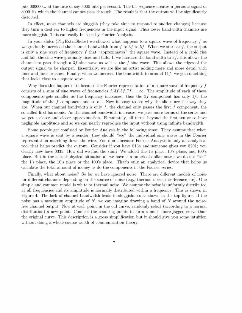
Finally, what about noise? So far we have ignored noise. There are different models of noisefor different channels depending on the source of noise (e.g., thermal noise, interference etc). Onesimple and common model is white or thermal noise. We assume the noise is uniformly distributedat all frequencies and its amplitude is normally distributed within a frequency. This is shown inFigure 4. The lack of channel bandwidth leads to sluggishness as shown in the top figure. If thenoise has a maximum amplitude of N , we can imagine drawing a band of N around the noise-free channel output. Now at each point in the old curve, randomly select (according to a normaldistribution) a new point. Connect the resulting points to form a much more jagged curve thanthe original curve. This description is a gross simplification but it should give you some intuitionwithout doing a whole course worth of communication theory.
7
InputSignal
Output SIgnal
Rise TimeInputSignal
Output SIgnal
Rise Time
(inertia only)
(inertia plus noise)
Figure 4: The two facets of channel distortion: inertia and noise
4.2 Nyquist Limit
We saw in the last section that if we sent a signal which contains higher frequencies than thechannel can pass, then the output will be distorted. Similarly, if we transmit bits at a rate thatexceeds the channel bandwidth, then the output will be distorted and the receiver will not be ableto recover the bits. In the next two sections, we will make this intuition more precise.
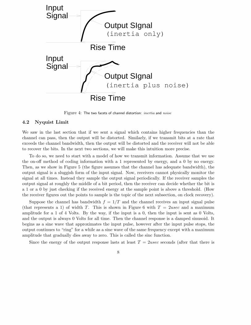
To do so, we need to start with a model of how we transmit information. Assume that we usethe on-off method of coding information with a 1 represented by energy, and a 0 by no energy.Then, as we show in Figure 5 (the figure assumes that the channel has adequate bandwidth), theoutput signal is a sluggish form of the input signal. Now, receivers cannot physically monitor thesignal at all times. Instead they sample the output signal periodically. If the receiver samples theoutput signal at roughly the middle of a bit period, then the receiver can decide whether the bit isa 1 or a 0 by just checking if the received energy at the sample point is above a threshold. (Howthe receiver figures out the points to sample is the topic of the next subsection, on clock recovery).
Suppose the channel has bandwidth f = 1/T and the channel receives an input signal pulse(that represents a 1) of width T . This is shown in Figure 6 with T = 2usec and a maximumamplitude for a 1 of 4 Volts. By the way, if the input is a 0, then the input is sent as 0 Volts,and the output is always 0 Volts for all time. Then the channel response is a damped sinusoid. Itbegins as a sine wave that approximates the input pulse, however after the input pulse stops, theoutput continues to “ring” for a while as a sine wave of the same frequency except with a maximumamplitude that gradually dies away to zero. This is called the sinc function.
Since the energy of the output response lasts at least T = 2usec seconds (after that there is
8
INPUT
OUTPUT
1 1 0 1
Ideal Sampling Pointsat receiver
Figure 5: Receivers recover the bits in the input signal by sampling the output signal as close to the middle of the bit
period as possible.
some energy but it dies away exponentially), one might think that it is safe to send the next bit Tseconds later. Indeed that is true.
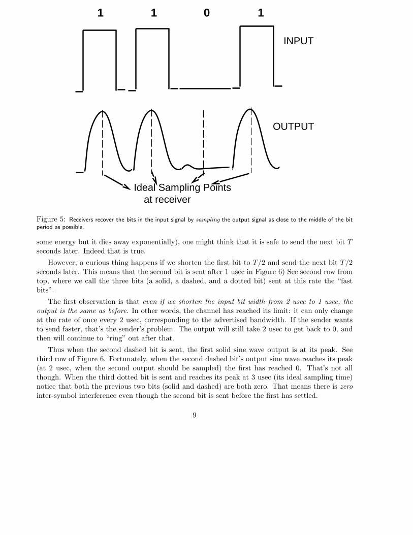
However, a curious thing happens if we shorten the first bit to T/2 and send the next bit T/2seconds later. This means that the second bit is sent after 1 usec in Figure 6) See second row fromtop, where we call the three bits (a solid, a dashed, and a dotted bit) sent at this rate the “fastbits”.
The first observation is that even if we shorten the input bit width from 2 usec to 1 usec, theoutput is the same as before. In other words, the channel has reached its limit: it can only changeat the rate of once every 2 usec, corresponding to the advertised bandwidth. If the sender wantsto send faster, that’s the sender’s problem. The output will still take 2 usec to get back to 0, andthen will continue to “ring” out after that.
Thus when the second dashed bit is sent, the first solid sine wave output is at its peak. Seethird row of Figure 6. Fortunately, when the second dashed bit’s output sine wave reaches its peak(at 2 usec, when the second output should be sampled) the first has reached 0. That’s not allthough. When the third dotted bit is sent and reaches its peak at 3 usec (its ideal sampling time)notice that both the previous two bits (solid and dashed) are both zero. That means there is zerointer-symbol interference even though the second bit is sent before the first has settled.
9
In general, we can make an argument by looking at the output wave form in Figure 6 that thereis zero intersymbol interference if we sent any sequence of bits every 1 usec. This is because anybit reaches its maximum 1 usec after it is sent; fortunately, at every usec after that, the outputcorresponding to that bit is 0 Volts despite its funny sinc shape. Since bits are only sampled atinstants that are multiples of 1 usec, this bit can never interfere with any subsequently sent bits.
It is easy to generalize this argument to replace the particular value of the bit width in Figure 6by T (instead of 2 usec) and see that the sender can send at a rate of 2/T without causing intersymbolinterference. But since T = 1/f where f is the bandwidth of the channel, the sender can send attwice the bandwidth of the channel.
Figure 6: Why one can signal at a rate of 2f and still avoid intersymbol interference. In practice, signalling at the
Nyquist Limit is not possible; limits like f are more plausible.
If we try a faster rate, we soon will find intersymbol interference. For example, in the last rowof Figure 6 we show an attempt to send the second dashed bit, much too early. In particular, theenergy of the solid is still around when the receiver samples the second bit. Even the first solidbit has to be sampled earlier (see figure) when its value has not reached its peak of 4 V and issay 3 V. But when the second dashed bit is sampled, the first solid bit has just reached its peak.Thus the sum of the two signals at the sampling instant of the second bit is now 7V. This maystill produce a 1 at the receiver but the two symbols (the solid and dashed) have interfered. Thisphenomenon, where the energy of a previous symbol spills over into the symbol time for the nextsymbol, is called Inter Symbol Interference (ISI).
10
While in this example, the receiver still gets the right output, imagine what happens if thereceiver sends a 1 as the solid bit followed by a 0 as the dashed bit. Then the dashed bit outputin Figure 6 will change to a flat 0 V. However, in this case if we send at the rate shown in the lastrow, at the second sampling instant, the receiver will measure 4 V and think it has received a 1,instead of a 0. This causes a bit error.
This example motivates the Nyquist limit which says that we cannot send symbols faster thana rate of 2B per second (if the channel bandwidth is B) without causing intersymbol interference.
4.3 Shannon Limit
In the previous subsection (see Figure 6) we sent 1 bit per pulse. If we were dealing with electricity,we might have a 1 be 5V and a 0 be 0 V. However, we might be able to send pulses of variouslevels. For example: 0, 2, 4 and 5V . In that case each pulse may actually have 4 possible values.Thus we can send multiple bits per pulse. With 4 levels, we can send two bits per pulse: 00 couldbe 0V , 01 could be 2V , 10 could be 4V , and 11 could be 5V . In general if we allow L levels, wecan have log L bits per pulse, where the log is taken to base 2.
Thus in the future, we use the word symbol to denote an individual pulse of energy. We call therate of sending pulses the signalling rate or the baud rate. The bit rate is the baud rate multipliedby the number of bits per symbol.
That immediately raises the question: can’t we transmit at as high a bit rate as we like bydividing each pulse into as many levels as we want? We can then transmit at mega-tera-gigabits.Right?
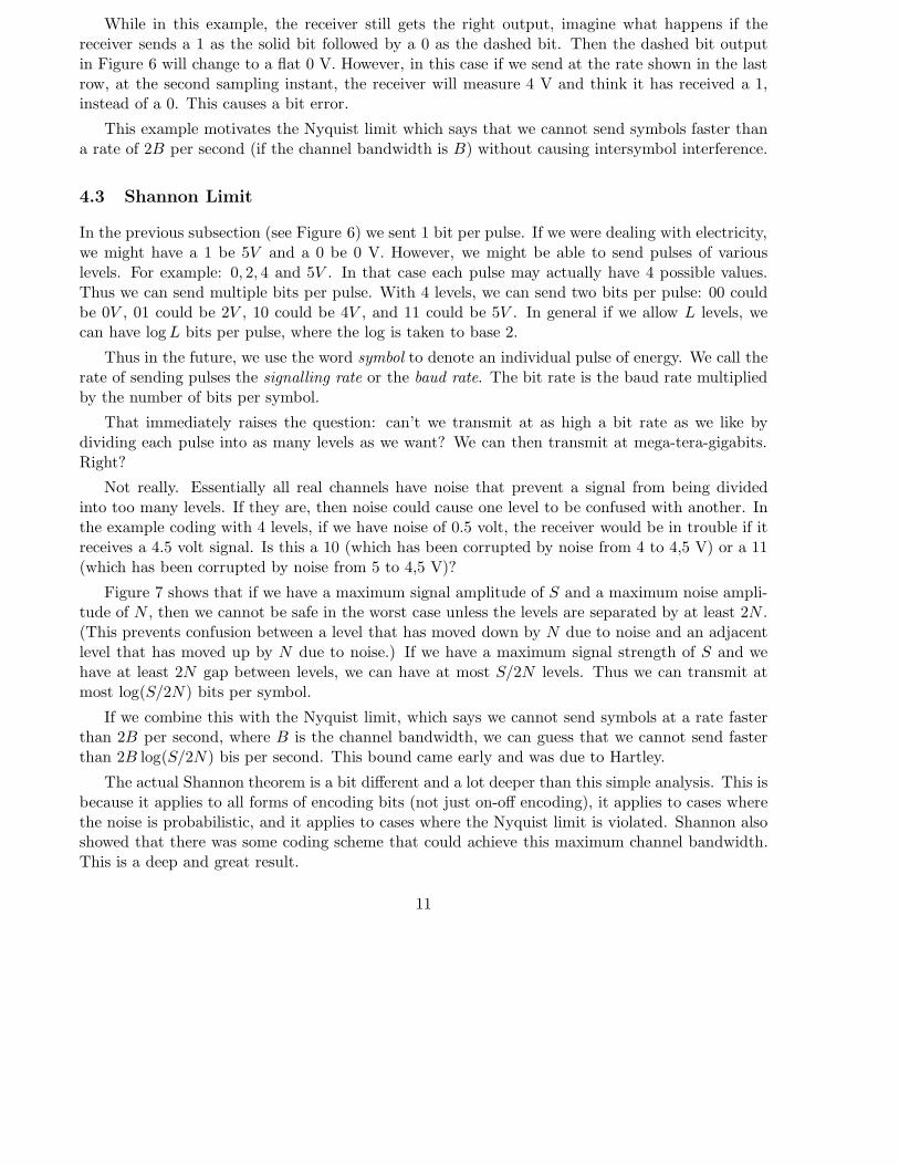
Not really. Essentially all real channels have noise that prevent a signal from being dividedinto too many levels. If they are, then noise could cause one level to be confused with another. Inthe example coding with 4 levels, if we have noise of 0.5 volt, the receiver would be in trouble if itreceives a 4.5 volt signal. Is this a 10 (which has been corrupted by noise from 4 to 4,5 V) or a 11(which has been corrupted by noise from 5 to 4,5 V)?
Figure 7 shows that if we have a maximum signal amplitude of S and a maximum noise ampli-tude of N , then we cannot be safe in the worst case unless the levels are separated by at least 2N .(This prevents confusion between a level that has moved down by N due to noise and an adjacentlevel that has moved up by N due to noise.) If we have a maximum signal strength of S and wehave at least 2N gap between levels, we can have at most S/2N levels. Thus we can transmit atmost log(S/2N) bits per symbol.
If we combine this with the Nyquist limit, which says we cannot send symbols at a rate fasterthan 2B per second, where B is the channel bandwidth, we can guess that we cannot send fasterthan 2B log(S/2N) bis per second. This bound came early and was due to Hartley.
The actual Shannon theorem is a bit different and a lot deeper than this simple analysis. This isbecause it applies to all forms of encoding bits (not just on-off encoding), it applies to cases wherethe noise is probabilistic, and it applies to cases where the Nyquist limit is violated. Shannon alsoshowed that there was some coding scheme that could achieve this maximum channel bandwidth.This is a deep and great result.
11
5 Clock Recovery Sublayer
We showed how the receiver obtains bits from the sender in Figure 5. In order to do so the receiverneeds to sample the output signal as close as possible to the mid bit periods (the dotted lines)because the signal reaches its highest value at these times and is less likely to be corrupted bynoise. Then the receiver applies some threshold function (e.g., if a 1 is encoded by 2V and a 0by 0V , then the receiver could decide that anything above 1V is a 1, anything below 1V is a 0.)Effectively the sequence of sampling instants is called the receiver clock.
The problem of clock recovery is to have the receiver dynamically adjust its receiver clock inorder to track (as closely as possible) the middle bit instants of the sender. Clock recovery consistsof two basic tasks: getting in phase (or figuring out when to sample the first bit) and staying inphase (keep the successive sampling instants synchronized).
The second problem would be very hard if the receiver did not have any information about theclock period of the source. For example, the same signal shown in Figure 8 could be decoded intwo completely different ways depending on the length of the bit/clock period. Thus we assumethat the receiver roughly knows the clock period of the sender by some a priori arrangement (suchas using similar quartz crystals in both sender and receiver).2
Thus the first problem (getting in phase) is always a issue. The second problem would not bean issue if the receiver and sender had exactly identical clocks. However, all clocks are slightlyinnaccurate and, over a period of time, the receiver and sender clocks will drift. Even if the senderand receiver are both installed with a 100 MHz clock, the receivers clock may tick slightly faster(say by 1 percent) than the senders, and so drift out of synchronization over long periods. Thus,over a long period, with no further correction, the receiver clock will drift arbitrarily far away fromthe sender clock. The result is that the receiver will sample the signal at the wrong instants. Inparticular if the receiver samples the signal during the start of a bit period during a transition froma 0 to 1 or vice versa, the receiver can get an arbitrary value, which can result in a bit error.
To solve the first problem, the sender generally sends a well-defined sequence of “training” bitsbefore it sends a stream of data bits. These bits get the receiver in phase. To solve the secondproblem, we can either rely on the accuracy of the receiver clock (and limit the number of bitssent to a small value) or we can ensure that the data will always have transitions. Transitions arechanges in signal amplitudes (for example, a change from 0 to a 1). Transitions provide cues thathelp the receiver stay in synch after getting in phase, even over a long stream of consecutive bits.It may help to think of the receiver clock as a stopwatch that can be started and restarted (andeven sped up and slowed down!) based on transitions.
However, real data bits do not either provide either training bits (sometimes called start bitsor a preamble) or guarantee transitions. To solve these problems, the top sublayer in the physicalsublayer is a coding sublayer that encodes the raw data bits fed to it by the Data Link Layer andcodes it to add training bits and transitions.
2Some modems do what is known as autobaud where the receiving modem figures out the speed of the sendingmodem. This works if the number of possible sender speeds is small (e.g., 9600 bps and 19,200 bps). The modemessentially tries to decode the incoming signal using both speeds. If there is some initial bit sequence the modemexpects, it can decide which of the two speeds is making “sense” and use that clock rate from then on. Clearly thisapproach does not work for an arbitrary range of speeds and if the initial sequence is completely arbitrary.
12

Thus we can define the following terminology. The physical layer will be handed some sequenceof bits to transmit. These bits will be coded by adding a preamble (or start bits) at the start andpossibly coding the data bits to force transitions. We will call the result a frame.
We now study two generic kinds of coding techniques: first asynchronous coding, and thenseveral examples of so-called synchronous coding. The former uses a small frame (10-11 bits) whilethe latter uses larger frame sizes and a larger preamble. We study how the receiver might do clockrecovery in both cases and discuss advantages and disadvantages.
5.1 Asynchronous Coding
In asynchronous coding, the sender physical layer is given a character of data to transmit. Thisdata character can be 5-8 bits and may also include a parity bit. The most common example isthe ASCII code in which letters of the alphabet and numbers can be encoded in 7 bits. In additionmost asynchronous codes also add an additional parity bit.3
The actually coding consists of the following rules. First, low amplitudes are used to encodea 1, and high amplitudes are used to encode a 0 (this is the oppposite of the convention we havefollowed so far!). We add a parity bit to each character and then “frame” the character with anextra start bit and 1-2 stop bits. The start bit is a 0 and the stop bit is a 1. Thus regardless ofthe value of the data character, the first bit sent is a 0 and the last bit is a 1. This is shown inFigure 9. Notice that the start bit is a high amplitude because of the peculiar way we code bits!
The times between the sending of characters can be arbitrary and hence this form of codinghas been called asynchronous. The word synchronous refers to a process that involves a clock orsome other time constraint; asynchronous implies that the time between characters is arbitrary.However, please note that the time between bits is not at all arbitrary but is controlled by the senderclock. If the time between characters is arbitrary, what happens to the line between characters?Essentially, the line amplitude is low (i.e., a 1).
Lets see how we solve the two clock recovery problems. Recall that the last bit of a codedcharacter is a 1 and the line reverts to a 1 level between characters. Thus since the first bit ofa character is a 0, we always guarantee a transition at the start of a new character regardless ofwhether the time between characters is zero or some other arbitrary time. Thus the receiver getsinto phase by watching for the low to high transition.
The second problem, that of staying in phase, is solved by a brute-force approach. We assumethe receiver and sender clocks are fairly close. Since there are only 10-11 bits in a frame, even ifthe receiver clock drifts, the receiver sampling points cannot drift too much by the end of a frame.More precisely, suppose the receiver begins sampling at the middle of the start bit. Then, evenif the receiver clock differs from the sender clock by 5 percent, over 10 bits the receiver samplingpoint will not drift by more than 50 percent. Thus the receiver sampling point will still stay withinthe corresponding sender bit period. In practice, we would would want the receiver clock to bemore accurate so that the last few bits are still sampled close to the middle of a bit period (andnot close to the edge of a bit where unpredictable things can happen).
3We will study parity bits later; they used to detect errors.
13
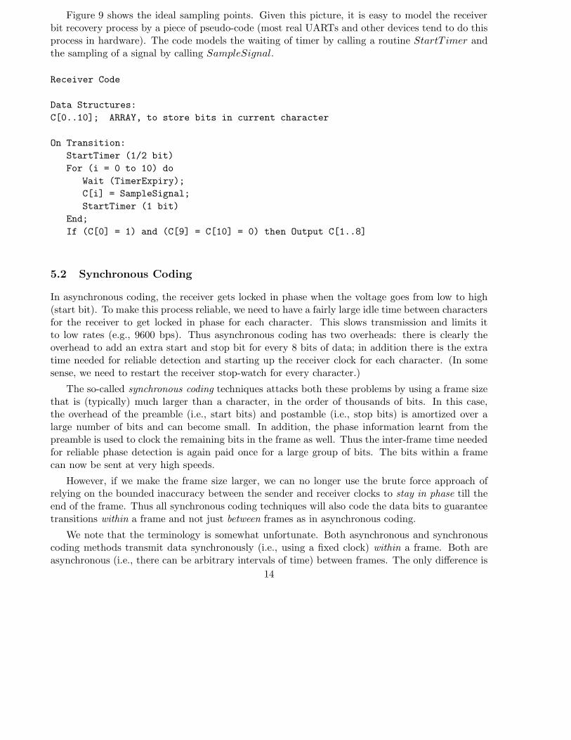
Figure 9 shows the ideal sampling points. Given this picture, it is easy to model the receiverbit recovery process by a piece of pseudo-code (most real UARTs and other devices tend to do thisprocess in hardware). The code models the waiting of timer by calling a routine StartT imer andthe sampling of a signal by calling SampleSignal.
Receiver Code
Data Structures:
C[0..10]; ARRAY, to store bits in current character
On Transition:
StartTimer (1/2 bit)
For (i = 0 to 10) do
Wait (TimerExpiry);
C[i] = SampleSignal;
StartTimer (1 bit)
End;
If (C[0] = 1) and (C[9] = C[10] = 0) then Output C[1..8]
5.2 Synchronous Coding
In asynchronous coding, the receiver gets locked in phase when the voltage goes from low to high(start bit). To make this process reliable, we need to have a fairly large idle time between charactersfor the receiver to get locked in phase for each character. This slows transmission and limits itto low rates (e.g., 9600 bps). Thus asynchronous coding has two overheads: there is clearly theoverhead to add an extra start and stop bit for every 8 bits of data; in addition there is the extratime needed for reliable detection and starting up the receiver clock for each character. (In somesense, we need to restart the receiver stop-watch for every character.)
The so-called synchronous coding techniques attacks both these problems by using a frame sizethat is (typically) much larger than a character, in the order of thousands of bits. In this case,the overhead of the preamble (i.e., start bits) and postamble (i.e., stop bits) is amortized over alarge number of bits and can become small. In addition, the phase information learnt from thepreamble is used to clock the remaining bits in the frame as well. Thus the inter-frame time neededfor reliable phase detection is again paid once for a large group of bits. The bits within a framecan now be sent at very high speeds.
However, if we make the frame size larger, we can no longer use the brute force approach ofrelying on the bounded inaccuracy between the sender and receiver clocks to stay in phase till theend of the frame. Thus all synchronous coding techniques will also code the data bits to guaranteetransitions within a frame and not just between frames as in asynchronous coding.
We note that the terminology is somewhat unfortunate. Both asynchronous and synchronouscoding methods transmit data synchronously (i.e., using a fixed clock) within a frame. Both areasynchronous (i.e., there can be arbitrary intervals of time) between frames. The only difference is
14

the size of a frame, which in asynchronous is limited to a few bits, while in synchronous it is muchlarger.
Types of Synchronous Coding: As in asynchronous coding, we can always represent a 1 byone voltage, and a 0 by another. This is called NRZ (non return to zero) coding. We could alwaysprefix a frame of data by an alternating string of 1’s and 0’s to get a good preamble to get intophase synchronization. However, there are several problems with this coding scheme. First, a longseries of 1’s (or 0’s) will contain no transitions and the receiver will not be able to stay in synch.Second, a long series of 1’s encoded at say 1.5 V will cause an average DC value of 1.5 V. Theproblem with this is that we have to interface to the line by direct physical connection instead ofusing transformers (which only pass non-DC values), which are safer and better. NRZ is sketchedin Figure 10.
A more popular scheme (used in Ethernets) is called Manchester encoding (see Figure 10). Herea 0 is encoded as -1.5 V for half a bit followed by 1.5 V for the remaining half bit. A 1 is encodedsymmetrically as 1.5 V followed by -1.5V. In some sense, in Manchester we are encoding a 0 by01 in NRZ, and a 1 by 10 in NRZ. Effectively, we are sending two coded bits for every real bittransmitted. Thus the transmission efficiency of Manchester is poor (real bits to coded bits, 50percent efficient).
However, the great advantage of Manchester is that it is self-clocking. This refers to the factthat every bit, regardless of its value, provides a transition that can be used to sample the bit value.For example, if we knew approximately where the half bit period was, our decoding algorithm couldbe: Wait for a transition at roughly the mid bit. Then start a timer for a quarter bit after that. Ifthe value is above some threshold, its a 0; else its a 1. In fact, many simple Ethernet clock recoverycircuits used this algorithm.
This algorithm does not really help to get into phase because a string of consecutive 1’s and astring of consecutive 0’s both produce almost identical waveforms (with transitions at every halfbit) except for a phase shift.4 To solve the phase problems, most Manchester encoders start a framewith the preamble 010101...01. This string has transitions only at the mid bits, which allows thereceiver to easily get in phase.
(Digression: The Ethernet frame format starts with a string of this sort followed by the bits 11.The reason for this is that even if the sender sends a fixed length string of 0101...01, the receivermay get in phase after an unknown number of bits and lose the first few bits. The last 11 at theend helps the receiver realize that the preamble is over and the data bits are beginning.)
Conceptually, Manchester can also be DC balanced as long as the two levels used are symmetricabout 0. Its lack of transmission efficiency makes it quite unpopular at higher speeds. Higher speedphysical layers (for example the 100 Mbit token rings) often use 4-5 codes, in which 4 data bits areencoded as 5 transmitted bits. This can be used to convert 4 consecutive 0’s to 5 bits with at leastone 1 in them which can guarantee transitions.
Another code which we discussed in class is AMI. In AMI, a 0 is encoded as 0V, but a 1 isencoded as alternating between 1.5V and -1.5V. This guarantees DC balance but does not guarantee
4This is easy to see if you think of a 0 as being 01 in NRZ and a 1 as 10 in NRZ. Both strings become a string ofalternating 1’s and 0’s in NRZ.
15
transitions. It also does poorer immunity to noise (lower signal to noise ratio) than, say, NRZ orManchester. This is because, using AMI, a noise signal of amplitude 0.75V can confuse the receiver.In Manchester and NRZ, it takes double the amount of noise (1.5 V) to confuse the receiver.
Based on this discussion we can compare different types of codes based on:
• Ability to Guarantee Transitions: This is probably the most important factor.
• Transmission Efficiency: The ratio of real to transmitted bits.
• Signal to Noise Ratio: Given the same maximum and minimum transmission levels, theamount of noise required to render a received signal ambiguous.
• DC Balance: The worst-case value of the average voltage value over an arbitrary string ofbits.
• Implementation Complexity: This is somewhat qualitative. Schemes like Manchestercoding are simpler to implement than, say, 4-5 coding or AMI which require memory of theprevious bits.
5.3 Broadband Coding
So far we have only talked of baseband coding which is coding using energy levels (say voltageor light). Another popular form of coding used by modems is broadband coding in which theinformation is modulated on a carrier wave of a certain frequency. For example, when a modemtransmits over a voice line, it is easier if the transmission is based on tones that are in the frequencybandwidth of the line.
The term modulation refers to changing the properties of the carrier to convey the requiredinformation. In Frequency Shift Keying (FSK), we let a high frequency encode a 0 and (say) alow frequency encode a 1. (Colloquially this is the same as singing high to encode a 0 and low toencode a 1.) Clearly this is done to make the data “sound” like voice so it can pass over a telephoneline. In Amplitude Shift Keying, we change the amplitude of the sine wave to encode a 1 or a 0.(Colloquially this is the same as singing loudly to encode a 0 and softly to encode a 1.) In phaseshift keying, we change the phase of the sine wave whenever we transition from a 1 to a 0 or viceversa.5
Even in these broadband coding schemes that are modulated on a carrier, the issues of clockrecovery and Nyquist and Shannon limits still remain. (Although, all the examples we have givenmotivating these issues used simple on-off encoding.) For example, in FSK we still have to samplethe sine wave periodically to decide its frequency at that point (or in that interval). Thus thoseissues are orthogonal to the type of coding used.
It is probably accurate to describe broadband coding as: analog coding of digital data andbaseband coding as digital coding of digital data. In baseband coding, the source puts out a digitalsignal (though it becomes an analog signal after channel distortion and noise.)
5When you change phase, the resulting sine wave appears to be discontinuous. For example, if you are at the peakof the sine wave and you have a phase change, you may instantaneously go to the crest of the sine wave.
16
5.4 Out of the Classroom, Into the Lab
We now turn to some practical issues concerning clock recovery in real communication systems.First, we consider the problem of noise. We have already seen that we need to make the signallevels coarse enough to avoid confusion due to noise when we sample the data. However, noise alsocomplicates clock recovery. We must synchronize the receiver clock to the sender clock in the faceof some possibly spurious transitions generated by noise.
Asynchronous clock recovery can be affected by noise but, for the most part, a spurious noisepulse will only cause one character to be lost and synchronization will be restored by the next char-acter reception.6. If, however, we used our simple minded algorithm for Manchester the situationcan be worse. Recall once we got into phase, we looked for the midbit transition and then sampledthe signal 0.25 bit periods later.
The problem with this simple scheme is that it can get completely thrown off by noise. If weassume that the receiver clock only drifts slowly away from the sender clock (once they are in phaseat the start of a frame) and that noise pulses are infrequent, then a better idea is to use informationin transitions to gradually correct the receiver clock. In other words, we prefer to use an averagingeffect. If the receiver clock is indeed behind the sender clock, then several transitions will causethe receiver clock to catch up; however, a single spurious transition caused by noise can only causelimited damage.
Phase Locked Loops: Most real life clock recovery circuits are based on Phase Locked Loopsthat embody this averaging principle. The idea is that the transitions in the received data are usedto generate a clock that is compared to the actual receiver clock. If the two do not coincide, therewill be a phase difference between the two clocks. This phase difference is used to speed up or slowdown the receiver clock to reduce the phase difference. This is actually done using a device calleda voltage controlled oscillator which produces a signal with different clock period depending on theinput voltage: the measured phase difference is used to generate the input voltage.
If there is no phase difference, the receiver is said to be in phase lock with the sender, and nochange is made to the receiver clock. It is called a phase locked loop because the circuit implementsa feedback loop that tries to keep the receiver in phase lock. A single spurious transition will onlycause the receiver clock to change speed slightly and will not significantly affect sampling times.A phase lock loop is designed to be like a flywheel with a fair amount of inertia: it takes a largenumber of impulses to get it moving, and hence is fairly secure against occasional noise.
Eye Patterns: Another useful technique used by most communication engineers in the lab isto inspect the so-called eye pattern. This allows the engineer to obtain a quick visual inspection ofmany aspects of transmission quality including intersymbol interference and sampling instants.
Consider an input signal consisting of a sequence of alternating 1’s and 0’s encoded using NRZas shown at the top of Figure 11. The corresponding output signal (assuming sufficient bandwidth)is shown by the dotted lines. Notice that the output rises and falls more slowly than the inputsignal because of the channel sluggishness. Now take the same input signal shifted in phase by 1
6It is, however, possible to have the receiver stay indefinitely out of synchronization with the sender if a certainsequence of characters is sent without any space. The only way to guarantee synchronization after an arbitraryamount of noise is to idle the line for a frame time, i.e., 10-12 bits
17
bit time (shown in the second row of Figure 11). The output signal is the same as in the first rowbut once again shifted in phase by 1 bit. If we superimpose these two output signals the dottedlines form the eye pattern shown in the third row of the figure. Notice that the dotted lines formwhat looks like a sequence of “eyes”.
If, however, we keep reducing the channel bandwidth, the output signal will rise even moreslowly to keep up with the input signal and the area enclosed within each eye will become smaller.Thus as inter-symbol interference increases, the “eye will close”. Thus the open area in eye providesthe designer with a quick visual inspection of the quality of the line and the coding used. Clearlythe ideal sampling instants are in the center of each eye.
In practice, the superimposition is done using an oscilloscope and the eye pattern is displayedon the screen. In practice, we do not confine ourselves to alternating 1’s and 0’s but take a shortpseudorandom string of 1’s and 0’s. The eye pattern then displays the superimposition of theoutput signals of every possible bit shift of the pseudorandom string. This is useful because thepseudorandom string includes transitions like a number of 1’s followed by a 0. Some channels mayhave data dependent flaws: for instance, the channel may be slower to return to a 0 after severalconsecutive prior 1’s. Such data dependent flaws can easily be spotted on the eye pattern.
6 Media dependent sublayer: Types of Media
In the example of using a flashlight to send Morse code, we saw that limits to signalling speedcorresponded to issues in the transmission sublayer; there were also issues having to do with clockrecovery. For the flashlight example, the media dependent sublayer corresponds to issues concerningthe technical aspects of the flashlight: for example, battery life, the range of the flashlight and itsclarity. These issues clearly affect data communication. If the user is mobile, we prefer a largebattery life; long distance communication requires flashlights with a large range.
Similarly, it is worth studying some aspects of the various kinds of media available because:
• Media Affects Protocols: The choice of media affects the way protocols have been designed orare evolving. We give examples below.
• Each Type of Media has its Range of Applicability: It is important to study and understandthe pros and cons of different media in order to design a network.
Thus some minimal information about the technical aspects of media is useful not just for thecommunication engineers working on the physical layer but for software engineers and protocoldesigners working at higher layers. We now elaborate.
6.1 Media Affects Protocols
We give some examples of how media has affected (and is affecting) protocol design. Some of thedetails should be clearer after the review of specific media.
18
• Available Bandwidth and Message Formats: The earliest networks used existing phonelines and were limited to low bandwidth voice links. Thus earlier protocols (e.g., currentInternet protocols) made valiant attempts to encode messages to save bits, and to send fewermessages. With the advent of fiber, this is becoming less of an issue and the latest Internetprotocols use more spacious formats and are less worried about sending messages.
• Broadcast LANs and use of Broadcast: With the personal computer came the inventionof the Ethernet (and other local area networks or LANs). The use of coaxial cable in Ethernetmade broadcasting essentially free (many stations could listen). This was heavily utilized byprotocols that work over such LANs. For example, the Internet protocols use a broadcastmechanism to find the address of an unknown station using the ARP protocol. Other LANprotocols used broadcast to distribute multiple copies of a packet for free (e.g., a distributedflight simulation.) With the advent of fiber, which is inherently point-to-point, broadcast isno longer free. Nevertheless software simulated broadcast is now considered essential and isnow available on the Internet.
• Building wiring affects Switching: The cost of wiring is significant because of labor costsand the need for right-of-way. Most buildings are wired hierarchically with lines running froma wiring closet on each floor. Thus a recent trend has been to replace these wiring closets withmore active devices like bridges and routers (intelligent hubs) and possibly ATM switches7
• Fiber to Coaxial Cable, Ethernets to rings: As fiber allows higher transmission ratesthan coaxial cable, vendors wanted to design higher speed LANs using fiber. Because fiber ispoint-to-point (one sender and one receiver) and hard to tap, it is hard to build an Ethernetlike LAN over fiber. Thus token rings, which consist of a number of point to point links in aring topology, began to get more popular in standards like 802.5 and FDDI.
• Twisted Pair to Fiber, Analog to Digital: The easiest way to send bits over fiber is toturn light on and off, which is inherently digital. Thus as the telephone companies replacedmore of their long haul network with fiber, they began to use baseband instead of broadbandsignalling. However, more recent advances in fiber and all-optical technology are based onanalog transmission. This may cause further changes.
• Infrared and wireless and low bandwidths again: Infrared technology, while inherentlylow bandwidth and short range, is becoming popular as a cheap, wireless connection forlaptops. The difficulty is that protocol designers can no longer assume high bandwidthseverywhere but must assume a large dynamic range. For example, there have been recentefforts to find a standard for compressing the spacious IPv6 (new Internet protocol) headersover mobile links!
The details are interesting but not as important as the message: it is good to be aware of thedetails of technology and media as they greatly influence protocols. As an analogy, architects aretrained to understand the details of types of construction material. Clearly, reinforced concreteand similar materials made skyscrapers possible.
7More about these devices later.
19

6.2 Types of Media: Pros and Cons
The most common media used for data communications are twisted pair, baseband and broadbandcoaxial cable, fiber, satellite, microwave, and infrared. We will spend a paragraph discussing eachtype of media, and then survey their advantages and disadvantages. More details can be found inother texts such as Tanenbaum and Stallings.
Notice that in our Hazel’s hats analogy, similar tradeoffs (speed, distance, latency, cost) occur inmany types of transport mechanisms. We use planes for long distance and cars for short distances.In some cases, for example, traveling in the mountains, a simple brute-force solution (!) may be touse a donkey.
Similarly, in networking it is important never to forget the brute force solution of shipping astorage device (e.g., magnetic tape, disk) by other transportation methods to the receiver. Tanen-baum has the beautiful example of shipping video tapes overnight by Federal Express across theU.S. Calculations show that the data rate is as fast as the fastest network speed and cheaper thanmost network transmission (except if the Internet is free for you!). One disadvantage of this schemeis that it has a high latency (1 day) if you have a small amount of data to send, a very commonfeature of most network traffic.8 However, it is a reasonable solution to the problem of backing upthe data at a site to a remote location because of its high bit rate or throughput.
Some important aspects of media are: distance or span, speed or throughput, latency, whetherthe media is wireless or wired, whether the media allows broadcast, the ability to eavesdrop on themedia, the ease of installing the media, noise immunity, and the power required for transmission.The pros and cons of the various media are summarized in Figure 12.
Distance influences whether the medium will be used in the local area, office, or backbonenetworks; speed affects the protocols that can be used over the lines (the backbone networksrequire high speeds).
Wired media like twisted pair, coax cable, and fiber require right of way in order to installthe wire, which is not easy in crowded cities and expensive even in offices and campuses.9 Wehave already seen that broadcast media like satellite and coaxial cable make possible cheap broad-cast protocols. Most broadcast media have problems with security because it is hard to preventunauthorized eavesdropping without using encryption.
Ease of installation is an important issue. Again wireless media are excellent bypass technologiesin developing countries because they get around the lack of infrastructure and the need for rightof way. Among wired media, fiber is light and easy to install. The old bulky Ethernet coaxialcable has since been replaced by lighter weight Thinwire Ethernet. Finally, fiber has excellent noiseimmunity to electrical noise and disturbances as it carries light; at the other extreme microwavescan be affected by rain, and infrared is easily absorbed by obstacles. Finally, low power radio wavesand infrared are useful for wireless computing and laptops because they do not require wires ormuch power.
Notice that each media type has its niche. Twisted pair, baseband coax, fiber, and infrared are
8If each click to a web page took a day to service, the web would not be very popular.9The labor cost for installation is typically more than the cost of the wire itself which is why it pays to install
extra wires for future use.
20
used in the local area and office. Broadband coaxial (e.g., television cable systems) are used in theintermediate (sometimes called metropolitan area and long distance); fiber and satellites are usedin the long distance. However, these niches change as technology evolves: for example broadbandcoaxial cable is being replaced by fiber in the backbone networks
6.3 Quick Description of Various Types of Media
We now give a quick description of the various kinds of media described in Figure 12.
Twisted Pair: Twisted pair is the standard telephone wire and easily available in the officeand the home. Sometimes known as Unshield Twisted Pair (UTP) this is a bunch of 8 wires twistedtogether in four pairs to reduce electrical intereference. This works because noise tends to go intoeach pair equally and if the signal is taken as the differnce between the signals in each pair, thennoise cancels out. The corresponding connectors are RJ-45 plugs. UTP is classified into differentlevels of quality according to its ability to transmit signals.
Standard Telephone wire is probably Category (or Cat) 1 and was unsuitable for sending dataat high rates. Using the standard Shannon Limit and a telephone bandwidth of 4 Hz, it is hard tosend data using standard data modems faster than 50 Kbps (without counting compression) andpossible at slightly over 100 kbps (with compression).
Two neat exceptions to this rule that you see every day are Ethernet Cables (the so-called Catx series) and DSL (that some people prefer to Cable). Let’s start with Ethernet cables. These aremuch higher quality twisted pair than telephone cables that effectively allow us a bigger bandwidthand higher data rate. You can’t do this over your telephone wiring but you can buy them say atFry’s.
While original Ethernet was carried over coaxial cable at 10 Mbps, so called Cat 3 cable wassoon prefered because it is lighted and easier to wire. You can go to Fry’s and purchase FastEthernet cable as Cat 5 to go up to 100 Mbps. This is because Cat 5 cable can send symbols asfast as 100 million times a second. Recall that Manchester encoding effectively sends 2 bits forevery bit. Thus instead, 100 Mbps Ethernet uses 4-5 encoding. Cat 6 (or even enhanced Cat 5)can carry 1 Gbps.
While the Cat 3, 5, and 6 cables are used by users to construct small local area networks,the telephone company also figured out a way to provide fairly high data rates (less than 10Mbps downstream and much less upstream) using so called DSL or ADSL (Asynchronous DigitalSubscriber Line). The key trick here is to realize that the standard twisted pair actually has a lotof bandwidth (it can every carry Ethernet) but it is artifically limited to 4 Khz by the telephonecompany using so-called loading coils. The loading coils are periodically inserted amplifiers allowtelephone calls to travel for long distances. The 4 Khz limit is also not a problem for voice becausehuman voice stays in that range.
To do DSL, they have to remove the loading coils (thus getting a much larger bandwidth), limityou to a small distance from the central office (because there are no loading coils to amplify yoursignal), and also need to make you asymmetric. Thus the closer you happen to be on the cablepath from the central office the higher your bandwidth. Many DSL lines are often terminated bya so-called DSLAM (DSL Access Multiplexor) which then leads on to the Internet.
21

Coaxial cable: consists of two concentric conductors in which the signal propagates as a wave.Baseband coaxial cable refers to using baseband signalling (e.g., digital signalling as in Ethernet)over coax cable. While this was the original form of 10 Mbps Ethernet, its thick clunky layout haslost out to UTP Cable. However, broadband cable is still very common.
Broadband coaxial cable refers to using broadband signalling (e.g., sending some modulatedhigh frequency signal as in Cable TV.) Baseband signalling has a smaller distance than broadbandsignalling; but broadband systems require amplifiers to periodically boost the signal. If you havecable at your home its because the cable company has run cable (with some fibre sometimes) to yourhome. Each cable’s bandwidth is divided into multiple 6 Mhz channels using frequency divisionmultiplexing, each of which can carry a TV channel (e.g., NBC, Fox).
However, cable modems work by reserving another 6 Mhz channel (just like a pseudo-channel)for downstream data sent from the cable head end (called the CMTS) to the individual data.Upstream data is sent in a smaller 2 Mhz channel. The 6 Mhz channel downstream allows potentiallyfast downloading times because using several bits per signal (they use Quadrature AmplitudeModulation to use multiple amplitudes and phases), cable can download at say 30 Mbps. Thecatch is that this bandwidth may be shared by lots of users and the cable companies impose ratecaps on individual users.
Fiber: Fiber is analogous to a flashlight being turned on and off and detected by an eye. Theflashlight is provided by a Light Emitting Diode (LED) or Laser that converts voltage into light;the eye is provided by a photodiode that outputs a voltage when light arrives. Bits are sent byturning the LED or laser on and off to emit on-off pulses of light. In fiber, the Nyquist and Shannonlimits are very high. The real limits occur due to chromatic and modal dispersion.
Dispersion refers to the spreading out of a narrow pulse of light when it is passed througha fiber. It is caused by a light signal splitting up into different components that take differentamounts of time to reach the destination. The first form of dispersion is modal dispersion in whicha light signal can be thought of as splitting into two components: one component travels straightthrough the fiber and the other takes a longer path, reflecting off the walls (see Figure 13).
If the difference in arrival times between the straight and longer paths is x seconds, then theoutput pulse seen by the receiver will be at least x seconds wide. This happens even if the inputpulse width is much smaller than x seconds. Hence, the term dispersion or spreading out. Dispersionplaces a limit on the bit rate: if the second bit is sent less than x seconds after the first bit, then thefaster component of the second bit can interfere (cause Intersymbol Interference) with the slowercomponent of the first bit, and can lead to bit errors.
Chromatic dispersion is similar except that the light breaks up into different frequencies (i.e.,colors) each of which have a different speed through the fiber and hence have different arrival times.
Thus the transmission rate is limited to one bit every x seconds, where x is the differencein arrival times between the fastest and slowest components of a light pulse. We can improvethe transmission rate by reducing x. To reduce or eliminate modal dispersion, the fiber width isreduced till there the only way (or mode) for light to travel is “straight down the middle”. This iscalled single mode fiber as opposed to multimode fiber. Single mode fiber is often at most 1 micronin diameter and more expensive than multimode fiber. To eliminate chromatic dispersion, we usemore accurate sources, like lasers, that emit light in a very small frequency range. Many high speed
22
fiber links use lasers together with single mode fiber, despite the increased cost when compared tousing LEDs and multimode fiber.
Satellites: Satellite transmission is roughly analogous to a person shouting in a valley andhaving others listen to the echoes. Transmitters are equipped with a transmitter (antenna) thansends high frequency waves (suitably modulated to convey the bit stream) to a satellite rotatingaround the earth. High frequency waves are very directional and propagate along the line oftransmission. The satellite acts like a repeater in the sky and repeats the signal on its downlink.Since the satellite is fairly high above the earth, a small beam signal repeated by the satellitespreads out into a larger beam by the time it arrives at the earth. Any receivers in the “shadow”of the satellite beam can use a dish, appropriately tuned, to receive the signal.
The earliest satellites were geosynchronous: by orbiting at 36,000 km, they could rotate at thesame speed as the earth.10 Thus at all times, the antenna could point in the same direction withoutthe need for an expensive steerable antenna. At this radius, the satellites can only be spaced 2degrees apart, which limits the number of geosynchronous satellites to 180.
However, there has been a flurry of recent activity involving low flying (and hence not geosyn-chronous) satellites. Since such satellites are visible only for a small period of time, these systemsuse a necklace of such satellites that cover the sky. As one satellite moves out of range, anothersatellite comes in view and there is a handoff procedure between the two satellites as in cellularphones. The Motorola Irridium project is the canonical example with 66 satellites in the sky al-lowing anyone (even on the North Pole) to talk to anyone in the world. Unfortunately, cell phonecalls using this technology cost too much (several dollars per minute) and so this reall cool ideawent bankrupt.
A second recent development is the use of small, low cost dishes which allows small users toafford the use of satellite technology.
The high frequency bands used allow fairly large transmission speeds. However, the need totravel a large distance in the sky makes the latency (i.e., the time for the first bit of a signal totravel from sender to receiver) large, in the order of 250 msec. This can be a serious problemfor interactive applications. TCP does poorly over satellite because it can increase its windowsize only after a round-trip delay because of its so-called slow start algorithm. However, satellitesscore over other media, including fiber by: being wireless (and hence avoiding right of way), beingbroadcast (which benefits broadcast applications such as publishing or video distribution, as wellas mobile nodes that stay within the satellite shadow) and by being distance independent (unlikewired transmission whose cost increases with distance.)
Microwaves, Infrared, and RF: Microwave, infrared, and radio frequency refer to the fre-quency of the waves used for transmission. Microwave transmission is similar to satellite transmis-sion except that the microwave signals (2-40 GHz) are sent between high towers without mediationthrough a satellite. Towers are used so that the signal path can avoid obstacles. Microwave wasused heavily in the long distance phone network because of the ability to avoid right-of-way andlabor costs, especially in crowded cities.
10Kepler’s law states that the period of a satellite is proportional to r1.5, where r is the orbital radius. Satellitesflying close to the earth have a period of 90 minutes. We need to go up to 36,000 km to get a period of 24 hours.
23
Infrared, also high frequency, fell out of favor many years ago because, like microwave andsatellite signals, it can be absorbed by obstacles. That can be an advantage in a single office,however, for a very local connection between a laptop and a server, which does not interfere withsimilar connections in nearby offices. Many recent laptops are coming equipped with an IR portfor wireless docking. Older IR ports offered speeds of around 100 kbps, but a new standard calledfast IR offers speeds of 4 Mbps.
Radio frequencies are lower frequencies than that of microwave, satellite and infrared. Lowerfrequency waves are omni-directional (spread out in all directions) and pass through obstacles.Recall that high frequency waves tend to be directional and absorbed by obstacles. The advantageof radio (or RF) transmission is the lack of a need for dishes (to receive the signal) and line-of-sighttransmission. The last factor is especially important for wireless LANs in, say, a college campus.However, the lack of directionality and the ability to penetrate obstacles implies that radio signalsat the same frequency can interfere. Thus early and current data transmission technologies thatused radio (e.g., ALOHA and MACAW, see later) have to detect and resolve collisions when userstransmit simultaneously.
6.4 Wireless Technologies
Wireless technologies are probably the most exciting development in physical layer technologies inthe last 10 years. All of us have used a wireless hot spot. The key is that we do not need a CAT-5Ethernet cable for our laptop to connect to the network. We use a wireless NIC Card to connectthrough the air to a router that can connect us to the network.
Wireless networks typically work in so-called infrastructure mode where communication occursthrough a so-called wireless access point or AP. A hot-spot at say Starbucks typically has an accesspoint. Communication is via radio frequencies. For example, the most common technology 802.11btransmits at up to 11 Mbps in the 2.4 to 2.485 Ghz frequency range. As we have seen, such radiowaves are good because they move in all directions and pass through obstacles. However, they dointerfere with microwaves and some cell phones. There are faster versions that are also being builtsuch as 802.11g at up to 54 Mbps which (unlike standard physical layer technologies) are backwardscompatible with 802.11 b.
When a network adminstrator configures an AP (this can be done at home or at Starbucks), itgives the AP a so-called SSID (or Service Set Identifier). When you do “view available networks”you see a list of SSIDs of all networks in your range. Each AP is also assigned a channel number.The 85 Mhz region from 2.4 to 2.485 is divided by frequency division multiplexing into 11 partiallyoverlapping channels. 1, 6, and 11 are non-overlapping. One could install three APs and configurethem at channels 1, 6, and 11 and get an overall bandwidth of up to 33 Mbps without interference.
In places like airports (or even homes, where you can often hear your neighbor’s AP), when awireless station first moves in, it can hear the so-called beacon frames containing the SSID sentby each AP in the area. In passive mode, the wireless station, scans all 11 channels, listeningfor beacon frames. It may receive two or more beacons from different APs on the same channel.If each AP has sufficient signal strength, then there is some selection algorithm in the laptop’sfirmware to pick one (or the user specifies), after which an “association” is made to the right AP
24

by sending some handshake messages. At that point, IP level connectivity is made via DHCPdiscovery messages (we will study this later). Instead of passively waiting for APs, wireless stationscan also actively send broadcast probe requests to APs in the area.
We will study the 802.11b access protocol after we have studied Ethernet. Like Ethernet, itfundamentally tries to send. If it detects a collision, it retransmits. However, the physical layerissues cause additional problems in 802.11b. In radio, it is possible to have three stations A, B,and C in a line with B (say the AP) in the center. Thus it possible that A can hear B, B can hearA and B, and C can only hear B. This is a headache because A could be transmitting happily toits AP. C who does not hear A now comes in brightly and starts sending to the AP B. However,C’s frame now collides with that of A at B, because B can hear both A’s frames and C’s frames.This is called the hidden terminal problem and it does not occur in wired networks.
Wireless networks can also work in so-called ad-hoc mode where wireless endpoints communicatedirectly with each other without an intermediary like an AP. This is an advantage when there is noinfrastructure such as a hot-spot. An example is Bluetooth. Two cell phones that are Bluetooth-enabled can communicate directly within short distances of each other. Although there is no AP,a group of Bluetooth enabled devices organize themselves into what is called a Piconet and electa master. All communication is mediated by the master. Thus without infrastructure, one of theBluetooth stations functions almost the same way as an AP in an 802.11b network.
While 802.11b and 802.11g offer considerable bandwidths, they require so-called hotspots wherethere are APs, and so so over a small distance (10 to 100 m). An extension of this data-centricapproach is so-called WiMax which allows larger distances via some different technologies but atsmaller speeds of say 4 Mbps. An alternative approach is being pursued by the cell-phone carrierswho already have considerable infrastructure and are masters of mobility as cars move from cell tocell. Their idea is to extend the cell network to also carry data so you can do Internet access inyour car via so-called 3G networks. For example, some users purchase a so-called EVDO card fromanywhere to allow Internet access during a road-trip across the United States.
As the two proponents have different stakeholders (cell phone manufacturers and operators for3G, and ISPs and cities who install 802.11 hotspots), both are being pushed hard. The 802.11technologies have the edge in terms of cost and bandwidth, but the 3G networks have the edgein terms of mobility and availability anywhere (even on a beach). As in all technology wars, it islikely they will co-exist.
6.5 Telephones
A final media topic that is worth understanding is not a media by itself but a vast system consistingof various kinds of media: the telephone network used currently to transport voice. There are tworeasons a computer network/protocol designer should be interested in the telephone network. Thefirst set of reasons are historical. The voice network was first designed for voice, and was thena natural candidate for long distance data transmission. Thus there are a number of strangeinteractions and kinks that affect data transmission which originated from the original mission tocarry voice.
The second set of reasons are futuristic. The telephone companies have a large physical invest-
25
ment in wires, switches and space; at the same time the voice market, at least in the U.S., cannotgrow much; a major source for increased revenues will be to adapt the phone network to carrydata and video.11. In fact, major portions of the backbone phone network use digital signallingand hardly require changes to carry data. However, the telephone companies’ plans for buildingworldwide data networks will necessarily evolve from the way voice networks are built today.
The first relevant aspect of telephony is that voice is circuit switched. When the digits are dialed,the local office sets up a path to the remote local office, and reserves a 4000 Hz bandwidth portionon the entire path that lasts the duration of the conversation. This is called circuit switching. Itworked well because users paying for a phone call typically talk all the time, with few pauses. (Bycontrast, most data transmission is bursty, with peaks followed by lulls. Thus the Internet followsthe post office model of communication called packet switching.)
The second relevant aspect of telephony is that the local loop from the local office to the usertypically uses one circuit (two wire) for voice in both directions. The backbone (also called toll orlong haul) network uses two circuits for voice in each direction in order to allow amplification overlong distances12.
The transition from two wire to four wire takes place at the local office through transformers.Thus some of the sent energy can leak back at the local office and some at the far end office tocause echoes. Since the far end echoes are especially annoying to users, some telephone lines useecho suppressors that sense the direction of transmission that is loudest and shut down the otherdirection. While this eliminates echoes, it also precludes full duplex data transmission in whichboth sides send data at the same time. (Note that most Internet transfers are full duplex; even ifa file is sent in one direction, acks are almost always flowing in the other direction.) To allow fullduplex modem operation, such modems need to transmit a pure tone that effectively shuts downthe echo suppressors. An even better device used more recently is an echo cancellor that figuresout the extent and timing of the echo and subtracts it from the reverse path at just the right time.The interaction between modems and echo suppressors is an example of a kink caused by voicerelated issues.
The third relevant aspect is that the backbone network is moving from analog transmissionover coaxial cable and microwave to digital transmission over fiber. This is because: digital signalsoffer better noise immunity, especially when repeated several times over long distances; fiber optics,when first introduced, seemed best suited to on-off kinds of encoding which are basically digital;digital switching and processing can be done easily and cheaply with digital electronics.
Since voice is an analog signal, voice first must be converted to digital (exactly the oppositetransformation in which modems convert digital signals to analog for broadband transmission!)at the points where the analog network meets the digital backbone. Since voice has frequencycomponents only in the 0-4000Hz range, it suffices13 to sample voice 8000 times a second.
11Note that the Internet and other data carriers have already started carrying voice and video; it is hardly surprisingthat voice carriers will start carrying data
12Amplifiers are directional devices that boost fading signals on their input to higher powered facsimiles on theiroutput.
13This is the converse of the other famous Nyquist result we studied: this one says that if we sample a band limitedsignal with highest frequency f at a rate of 2f , then we can recover the signal. Its easy to see why you need 2f ifyou think of sampling a simple sine wave of frequency f .
26
The voice signal, after sampling, becomes a set of pulses at the sampling instants. The ampli-tudes at these pulses are quantized into 256 levels and then the level is encoded using 8 bits. Since8 bits are sent 8000 times a second, this requires a data rate of 64,000 bits a second. This is calledpulse code modulation or PCM and the device doing the coding is often called a codec. Notice theenormous bandwidth expansion to carry voice from 4000 Hz (which can barely support 19.2 kbpsmodems) to 64 kbps.
64 kbps has become an international standard for digital voice. Because of this, 64 kbps is alsoa convenient multiple for the phone company to offer backbone data services. In fact, the earlyproposals for narrowband ISDN offered data channels of this speed. Many long distance telephonelines (both coax and fiber) can carry much larger bit rates. Thus it makes sense to package multiple64 kbps voice channels on a single physical line. One standard for doing this in the U.S. is theso-called T1 hierarchy in which the lowest level offers 24 digital voice channels for an aggregatebandwidth of 24 * 64 = 1.5444 Mbps. T2 and T3 links offer even higher bandwidths. These magicnumbers are important because they represent the most easily available long distance bandwidthsthat a computer network company can purchase from the phone companies.
Although the T1 hierarchy is still quite common in the U.S., Europe and Japan use differentstandards for packaging multiple digital voice channels. SONET is an emerging standard to in-terconnect these various systems so they can internetwork. SONET also allows this hierarchy togrow indefinitely beyond the T1 hierarchy as fiber speeds continue to grow. Now T1 frames can bethought of as a linear bit string with an 8 bit slot for each of 24 channels (yielding 192 bits totalplus some control bits, the frame is repeated 8000 times a second). SONET frames can be bestthought of as two dimension frames with columns for lines being multiplexed and pointers so thatthe useful information needed not start at the beginning of a column. Users buying high speeddata lines can now obtain links in units of the SONET hierarchy: STS-1 (51 Mbps) STS-3 (155M), STS-12 (622 M), etc. Notice that T1 is closest to STS-3 and that 3 STS-1s can be mergedinto a STS-3. Finally, whenever SONET framing is used over optical lines, these standards arecorrespondingly called OC-1, OC-3 etc, where the OC stands for optical carrier.
A fourth relevant aspect of telephone networks is the way digital switching is done using T1and SONET frames. Recall that a voice call must reserve the appropriate bandwidth on all linksin the path from the source local office to the destination local office. Consider a path from S to Ato D, where S and D are the source and destination local offices. If S to A is a T1 line, our voicecall may be assigned say the 10th slot on this T1 line. Similarly if A to D is another T1 line, whenthe call was set up, our voice call may be assigned say the 23rd slot on the T1 line from A to D.
The switching problem at node A is to take all the information arriving on a slot of an incomingline and send it out on a possibly different slot of the outgoing line. Because the slots can possiblybe different, this is called a Time Slot Interchange switch. This can be accomplished easily byreading all incoming frames into the switch memory. When outgoing frames are assembled, foreach slot in the outgoing frame, the switch consults a table that tells the switch the location (slotnumber and incoming line) of the data to fill this outgoing slot. This table must be updatedwhenever new voice calls get set up and old calls are cancelled. However, the switching process caneasily be accomplished by a processor and memory.
The reason that time slot interchange switching is relevant is that it suggest a technique for data
27
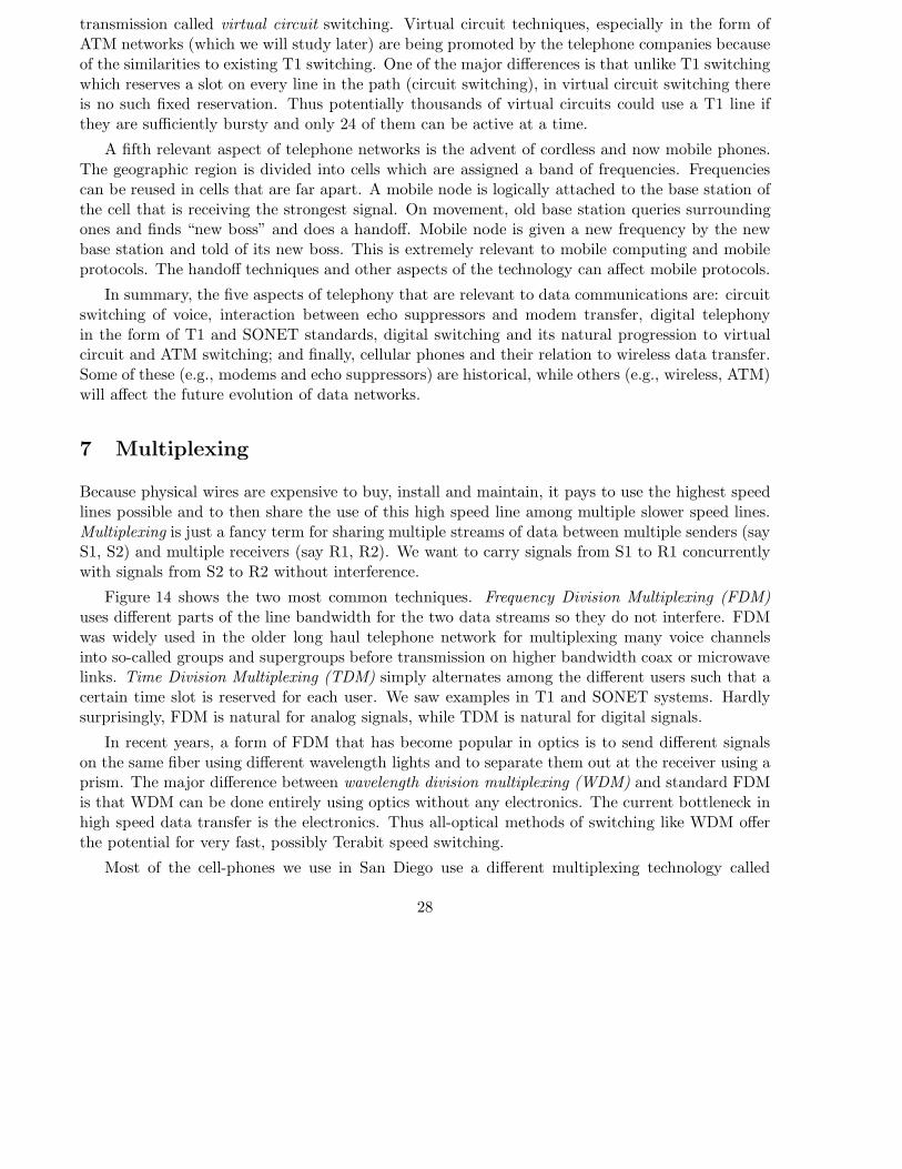
transmission called virtual circuit switching. Virtual circuit techniques, especially in the form ofATM networks (which we will study later) are being promoted by the telephone companies becauseof the similarities to existing T1 switching. One of the major differences is that unlike T1 switchingwhich reserves a slot on every line in the path (circuit switching), in virtual circuit switching thereis no such fixed reservation. Thus potentially thousands of virtual circuits could use a T1 line ifthey are sufficiently bursty and only 24 of them can be active at a time.
A fifth relevant aspect of telephone networks is the advent of cordless and now mobile phones.The geographic region is divided into cells which are assigned a band of frequencies. Frequenciescan be reused in cells that are far apart. A mobile node is logically attached to the base station ofthe cell that is receiving the strongest signal. On movement, old base station queries surroundingones and finds “new boss” and does a handoff. Mobile node is given a new frequency by the newbase station and told of its new boss. This is extremely relevant to mobile computing and mobileprotocols. The handoff techniques and other aspects of the technology can affect mobile protocols.
In summary, the five aspects of telephony that are relevant to data communications are: circuitswitching of voice, interaction between echo suppressors and modem transfer, digital telephonyin the form of T1 and SONET standards, digital switching and its natural progression to virtualcircuit and ATM switching; and finally, cellular phones and their relation to wireless data transfer.Some of these (e.g., modems and echo suppressors) are historical, while others (e.g., wireless, ATM)will affect the future evolution of data networks.
7 Multiplexing
Because physical wires are expensive to buy, install and maintain, it pays to use the highest speedlines possible and to then share the use of this high speed line among multiple slower speed lines.Multiplexing is just a fancy term for sharing multiple streams of data between multiple senders (sayS1, S2) and multiple receivers (say R1, R2). We want to carry signals from S1 to R1 concurrentlywith signals from S2 to R2 without interference.
Figure 14 shows the two most common techniques. Frequency Division Multiplexing (FDM)uses different parts of the line bandwidth for the two data streams so they do not interfere. FDMwas widely used in the older long haul telephone network for multiplexing many voice channelsinto so-called groups and supergroups before transmission on higher bandwidth coax or microwavelinks. Time Division Multiplexing (TDM) simply alternates among the different users such that acertain time slot is reserved for each user. We saw examples in T1 and SONET systems. Hardlysurprisingly, FDM is natural for analog signals, while TDM is natural for digital signals.
In recent years, a form of FDM that has become popular in optics is to send different signalson the same fiber using different wavelength lights and to separate them out at the receiver using aprism. The major difference between wavelength division multiplexing (WDM) and standard FDMis that WDM can be done entirely using optics without any electronics. The current bottleneck inhigh speed data transfer is the electronics. Thus all-optical methods of switching like WDM offerthe potential for very fast, possibly Terabit speed switching.
Most of the cell-phones we use in San Diego use a different multiplexing technology called
28
CDMA (Code Division Multiple Access). Each user is given a certain code which is a sequence of-1’s and 1’s say -1, 1, 1, -1. The voice is converted to digital and sent a bit at a time. Instead ofsending a single bit 1, the bit is multiplied by the code and sent. A 1 is written as 1 as usual but a0 is represented by -1. Thus a 1 would be sent as -1, 1, 1, -1. On the other hand, a 0 is sent as 1,-1, -1, 1. The key is that each user is given a different code as part of their SIM card. Even if theytransmit at the same time, a property of the codes allow them not to interfere. The slides in classgive you an example.
The standard form of CDMA requires each user to use a different code and to be synchronizedso they start at the same time. This works fine for Base to Mobile communication, but not for twomobiles talking to the same base station because the two mobiles will not necessarily synchronizewhen talking at the same time. Thus what really is used in our Qualcomm phones is what is calledasynchronous CDMA. Instead of using a fixed code each user is given a psuedo-random sequencesuch that if there are only a small number of users at the same time, the probability that there willbe appreciable interference is small.
In other words, TDM, FDM, and even standard CDMA are fixed multiplexing systems whileCDMA is a statistical multiplexing technique. Thus asynchronous CDMA can use the bandwidthmore efficiently. As Wikipedia says, “In a bursty traffic environment like mobile telephony, theadvantage afforded by Asynchronous CDMA is that the performance (bit error rate) is allowed tofluctuate randomly, with an average value determined by the number of users times the percentageof utilization. Suppose there are 2N users that only talk half of the time, then 2N users can beaccommodated with the same average bit error probability as N users that talk all of the time.”
Bluetooth uses another approach to having multiple users share the channel which is analogousto CDMA, as FDM is analogous to TDM. The idea is that users hop between frequencies (asopposed to using different codes in different time slots).
8 Interconnection
We have already seen that the telephone network can appear to be a single physical medium todata users when it actually consists of a number of different physical media that are interconnected.For example, in the T1 and SONET discussion, we had interconnections through T1 and SONETswitches. Even ordinary twisted pair and coaxial cable are often extended through the use ofrepeaters to allow larger distance coverage and better signal-to-noise ratio of the received signals.A repeater is a device that clocks bits coming in on one physical line and clocks them out on anoutgoing line; thus repeating bits will restore the signal levels of a bit whose level is “drooping”.
Note therefore that the physical layer (and the Data Link layer) may appear to be working overa single hop (as we sketched in our introductory lectures). However, they actually may consist ofa number of interconnected pieces of wire. However, the details of the interconnection must betransparent to the end users: the end users can therefore imagine that they are working over asingle hop. Thus T1 switches and Ethernet repeaters are transparent to end users. We will seelater that routing and transport interconnections are not transparent and the user is actually awareof the possible multiple hops in the path.
29

9 Review
After all this information, we stop to catch our breaths and ask what the physical layer was about.Recall that we divided the task of the physical layer (see Figure 2) into three parts: the media ortransmission sublayer, the media dependent sublayer, and the coding and clock recovery sublayers.
In the Media Sublayer, we studied the use of Fourier Analysis to figure output signal behavior.We then studied the Nyquist limit which shows that signalling faster than the channel bandwidthcauses Inter-Symbol Interference. Finally we studied the Shannon limit which showed that signallevels can’t be finer than noise, so we can only increase the bit rate to a certain point by increasingthe number of levels.
We then studied the Coding and Clock Recovery Sublayer. We showed that clock recovery wasthe problem of calculating optimal receiver sampling times in the presence of clock drift and noise.We showed how to get into phase with a preamble and to correct for clock drift by using informationprovided by transitions in the bit stream. We saw many coding techniques to generate preamblesand to force transitions, including asynchronous and synchronous codes.
We then studied the details of several kinds of media. Don’t be confused by the details butrecall the two important lessons: media affects protocol design, and each media has pros and cons(see Figure 12). We also studied the telephone system, with its collection of media, and arguedthat some aspects of the telephone system (partly because of historical reasons and partly becauseof future trends) greatly influence data communications.
The sublayer model can help you break up a complex implementation into manageable partsthat you can understand. As in all layered models, it also shows you that parts can be interchangedif desired as long as the interfaces are maintained. For example, Figure 15 shows a sublayered modelof a typical modem transmission that uses asynchronous coding, frequency shift keying for mediatransmission, and telephone wire. Figure 16 shows a sublayered model of Ethernet transmissionusing Manchester encoding, baseband on-off voltage signalling, and coaxial cable. The sublayermodel makes you realize that one could, in principle, do Manchester encoding combined with Phaseshift Keying over a telephone line. This is no different conceptually from using say Appletalk toreplace the Internet (IP) routing layer.
Finally, we studied the problems of multiplexing and interconnection at the physical layer.Multiplexing is a way of sharing several logical signals on a single physical line using techniquessuch as FDM and TDM. Interconnection is a way to combine multiple physical layer pipes to looklike one logical bit pipe.
10 Conclusion
We have finished studying the details of the physical layer. As we study the Data Link and higherlayers, we can simply think of the physical layer as providing a bit or symbol pipe between twonodes that can sometimes lose or corrupt bits/symbols. We next move on to studying the DataLink layer, which (we will see) provides a frame pipe between two nodes. We will see why thisform of framing is necessary and why it makes possible new functions such as addressing and error
30
detection.
Before we move on, we remark that all layers tend to solve similar abstract problems althoughthey appear in different guises at each layer. Here is a list of some of these problems and acorresponding example in the physical layer:
• Multiplexing and resource allocation: Handling multiple users economically using acommon set of resources (e.g., TDM, FDM at the physical layer)
• Addressing: Separating out traffic for multiple receivers and senders. (Null issue for thephysical layer)
• Error Control: Techniques to deal with common errors. (At the physical layer we dealwith noise and lack of bandwidth by spacing levels far apart, sending below Nyquist limit,sampling at mid bit, etc.)
• Synchronization: This is a generic term used to ensure that state variables in the receiverand sender are kept in some prescribed relation despite errors and uncertainty in timing.(The classic synchronization problem at the physical layer is to keep the intervals betweenthe sender and receiver clock instants very close to each other despite clock drift and noise.)
• Interconnection: This is mostly unique to network systems but can be done at every layer.At the physical layer this done by repeaters that read bits in from one line and transmitthem to other lines. It is also done by T1 switches that perform a form of routing functionbesides being a bit repeater. It is important that each layer interconnection device only usesthe information available at that layer — i.e., bits at the physical layer, frames at the DataLink Layer, packets at the routing layer.
We will see that other layers have other forms of these problems to solve. In fact, most systemssolve the same problems. For example, an Operating System must multiplex and share CPU timeand memory among many users; it must have techniques for addressing resources like memory,devices and disk; it must ensure consistency in the face of errors like crashes; it must ensuresynchronization in the face of interrupts and other concurrent activity. This general view of systemsis a somewhat profound idea. You will realize this more and more as you study more kinds of systemsin fields as varied as databases and computer architecture.
In network systems another observation is that many layers solve the same problems repeatedlye.g., interconnection, multiplexing and addressing are solved at different layers in different ways.Part of this is because solutions at different layers have different tradeoffs (for example, solutionsat low layers can be applicable more generally to most protocols but may be less efficient becausethey do not have enough information to specialize to the particular protocols running over them),but part of the problem is that each layer evolved and solved its problems independently. In factthere have been recent proposals to solve some of these problems (especially multiplexing) just onceat some layer, and not have the same function repeated unnecessarily at all layers.
31

1
2
3
0
S
N
N
S = Maximum Signal Amplitude
N = Maximum Noise Amplitude
log(S/2N) bits per signal2 B signals/sec (Nyquist)
Naive Bound = 2 B log(S/2N)
Shannon Bound = B log(1 + S/2N)
THE SHANNON BOUND
Figure 7: The Shannon limit shows that we cannot divide the maximum signal amplitude into too many levels without
getting confused due to noise. If the noise has amplitude N , and the signal levels are spaced 2N apart we are safe.
32

0 0 10 1 1 1 0 0
0 0 1 1 0
Figure 8: Why the receiver and sender must have some idea of the clock period.
33
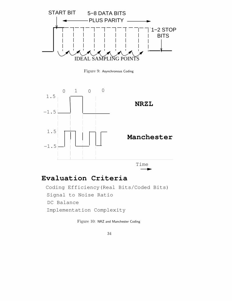
START BIT
IDEAL SAMPLING POINTS
BITS1−2 STOP
5−8 DATA BITSPLUS PARITY
Figure 9: Asynchronous Coding
Time
0 1 0 0
−1.5
1.5
−1.5
1.5
NRZL
Manchester
Evaluation CriteriaCoding Efficiency(Real Bits/Coded Bits)
Signal to Noise Ratio
DC Balance
Implementation Complexity
Figure 10: NRZ and Manchester Coding
34

0 1 0 1 0 1
0 1 0 1 0 1
Superposeto get
eye pattern
Figure 11: By superimposing the output of many shifted versions of a bit pattern, we can obtain an eye pattern. Ideally
the eye should be wide open; as intersymbol interference increases, the eye will shut.
TwistedPair
AnalogCoax
DigitalCoax
Satellite
Microwave
Fiber
Bandwidth Span Disadv Adv
< 1Mbps 1−2Km low speed cheap,easyto install
10−100Mbps 1−2km hard to tap,install
broadcast
100−500Mbps
100km
exp.analogamplifiers
cable companiesuse it now!
100−500Mbps worldwide prop delayantennas
no right−of−waycost does notdepend on distance
no right−of−way
100kmterabits
10−100Mbps
100km
fog outages
no broadcast security
isolationbandwidth
Infrared
no mobility
< 4 Mbps 3 m wirelessobstacles RF 115 kbps 1 km for infrared
Figure 12: Pros and Cons of Various Media: a summary
35

Sender Receiver
Direct SignalSlow Signal
Figure 13: Modal dispersion in fiber
S1
S2
S1
S2S1 S2 S1 S2 . . .
S1
S2
S1
S2
TIME DIVISION MULTIPLEXING (TDM)
FREQUENCY DIVISION MULTIPLEXING (FDM)
MULTIPLEXING (SHARING)
Figure 14: Time and Frequency Division Multiplexing
36
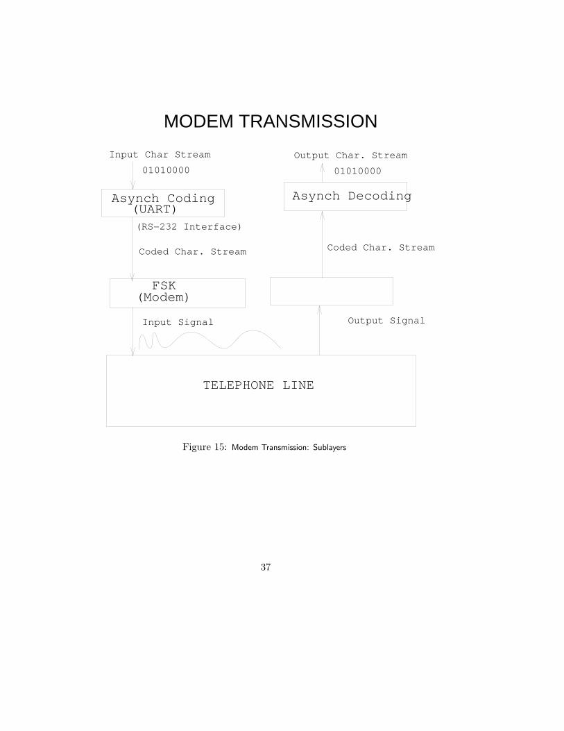
Input Signal Output Signal
01010000 01010000
MODEM TRANSMISSION
Input Char Stream Output Char. Stream
Asynch Coding (UART)
FSK (Modem)
Asynch Decoding
TELEPHONE LINE
Coded Char. StreamCoded Char. Stream
(RS−232 Interface)
Figure 15: Modem Transmission: Sublayers
37

Sublayer Sublayer
Input Bit Stream
Input Signal Output Signal
Output Bit Stream
Media Transmission Media Reception
Coded Bit Stream Coded Bit Stream
01010000 01010000
ETHERNET TRANSMISSION
Decoding
MEDIA (COAXIAL CABLE)
Manchester Synchronous Coding
Figure 16: Ethernet Transmission: Sublayers
38


![Citrix Receiver for Mac 12.8 · If Citrix Receiver for Mac is configured to use a proxy server, Secure Socket Layer (SSL) connections can fail. [#640652] Compared to: Citrix Receiver](https://img.dokumen.tips/doc/110x75/5e4b26f4f7c0fb679b323bf0/citrix-receiver-for-mac-128-if-citrix-receiver-for-mac-is-configured-to-use-a-proxy.jpg)