Embed Size (px)
Citation preview

ENG.20070322.0011ENG.20070322.0011
DesignDesign CalculationCalculation oror AnalysisAnalysis CoverCover SheetSheet 1.1. QA:QA: QAQASSCSSC
2.2. PagePage 11 CompleteComplete onlyonly applicableapplicable items.items.
3.3. SystemSystem 14.14. DocumentDocument IdentifierIdentifier
ReceiptReceipt FacilityFacility 200-DBC-200-DBC-RFOO-OORFOO-OO 11OO-OOO-OOAOO-OOO-OOA 5.5. TitleTitle
ReceiptReceipt FacilityFacility (RF)(RF) ShearShear WallWall DesignDesign 6.6. GroupGroup
Civil/Structural/ArchitecturalCivil/Structural/Architectural 7.7. DocumentDocument StatusStatus DesignationDesignation
DD PreliminaryPreliminary [gJ[gJ CommittedCommitted DD ConfirmedConfirmed DD Cancelled/SupersededCancelled/Superseded
8.8. Notes/CommentsNotes/Comments
TotalTotal NumberNumber ofofAttachmentsAttachments PagesPages
SeeSee CalculationCalculation SectionSection 55 1717
RECORDRECORD OFOF REVISIONSREVISIONS
11.11. 12.12. 13.13. 14.14. 15.15. 16.16. 9.9. 10.10. TotalTotal ## LastLast OriginatorOriginator CheckerChecker EGSEGS Approved/AcceptedApproved/Accepted No.No. ReasonReason ForFor RevisionRevision ofof Pgs.Pgs. Pg.#Pg.# (Print/Sign/Date)(Print/Sign/Date) (Print/Sign/Date)(Print/Sign/Date) (Print/Sign/Date)(Print/Sign/Date) (Print/Sign/Date)(Print/Sign/Date)
OOAOOA InitialInitial IssueIssue 4141 A17A17 SectionsSections 1-71-7 R.R. NelsonNelson J.J. BissetBisset R.R. RajagopalRajagopal AttachmentsAttachments A,A, B,B,
&D&D (J,1J/Jv.-.(J,1J/Jv.-. J.~J.~ .--.,.--., ~..i?~~~t.~..i?~~~t......... _,_, '3/2-1'3/2-1 )07)07 3/;})3/;}) JJ-6JJ-6UU ??dd 3fi·3fi· ZOOTZOOT ~1~1AttachmentAttachment CC
R.R. BaylosisBaylosis
£I!r;/?((£I!r;/?((3jZ.13jZ.1 'Z~7'Z~7

Title: Receipt Facility (RF) Shear Wall Design Document Identifier: 200-DBC-RF00-00100-000-00A
DISCLAIMER
The calculations contained in this document were developed by Bechtel SAIC Company, LLC (BSC) and are solely intended for the use of BSC in its work for the Yucca Mountain Project.
2 March 2007

Title: Receipt Facility (RF) Shear Wall Design Document Identifier: 200-DBC-RF00-00100-000-00A
TABLE OF CONTENTS Page
LIST OF FIGURES 4 LIST OF TABLES 4 LIST OF ACRONYMS 5
1. PURPOSE 6
2. REFERENCES 2.1 PROCEDURES/DIRECTIVES 6 2.2 DESIGN INPUTS 6 2.3 DESIGN CONSTRAINTS 7
2.4 DESIGN OUTPUTS 7
3. ASSUMPTIONS 8 3.1 ASSUMPTIONS REQUIRING VERIFICATION 8 3.2 ASSUMPTIONS NOT REQUIRING VERIFICATION 8
4. METHODOLOGY 9 4.1 QUALITY ASSURANCE 9 4.2 USE OF SOFTWARE 9 4.3 DESIGN METHOD 9
5. LIST OF ATTACHMENTS 10
6. BODY OF CALCULATION 10 6.1 SHEAR WALL DESIGN FORCES 10 6.2 LIMITING SHEAR WALL CAPACITY 15 6.3 SHEAR WALL DESIGN 19
7. RESULTS AND CONCLUSIONS 20 7.1 RESULTS 20 7.2 CONCLUSIONS 23
8. DIRECTORY OF FILES LISTED ON CD 1 of 1 (ATTACHMENTS B thru D) 24
ATTACHMENT A Floor Plan and Wall Elevations A1
ATTACHMENT B Shear Wall Design Templates (North-South Walls) CD 1 of 1
ATTACHMENT C Shear Wall Design Templates (East-West Walls) CD 1 of 1
ATTACHMENT D Excel and Word files relevant to this calculation CD 1 of 1
3 March 2007

Title: Receipt Facility (RF) Shear Wall Design Document Identifier: 200-DBC-RF00-00100-000-00A
FIGURES Page
Figure 1 Shear Wall Local Coordinate System 11
TABLES Page
Table 1 Shear Wall Design Forces 13
Table 2 Out-of-Plane Accelerations for DBGM-2 15
Table 3 Limiting Shear Wall Capacity 17
Table 4 Shear Wall Design Summary 21
4 March 2007

Title: Receipt Facility (RF) Shear Wall Design Document Identifier: 200-DBC-RF00-00100-000-00A
ACRONYMS
3D Three-dimensional
FE Finite element
FEM Finite element model
RF Receipt Facility
C/C Center to Center
DBGM Design Basis Ground Motion
ACI American Concrete Institute
SRSS Square Root of Sum of Squares
SSI Soil Structure Interaction
TAD Transport, Aging, and Disposal
YMP Yucca Mountain Project
DL Dead Load
LL Live Load
5 March 2007
Title: Receipt Facility (RF) Shear Wall Design Document Identifier: 200-DBC-RF00-00100-000-00A
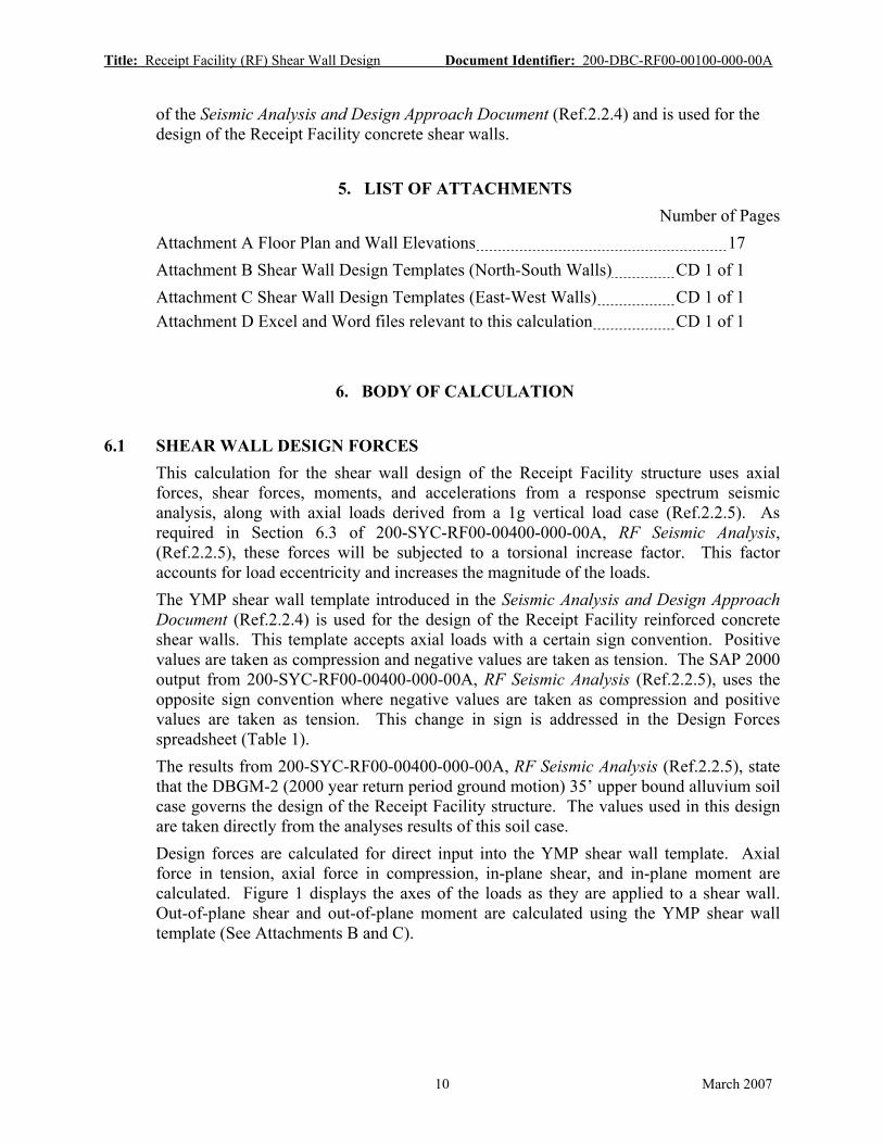
1. PURPOSE
The purpose of this calculation is to perform a preliminary design of the reinforced concrete shear walls for the RF structure. The RF can be classified as a low rise shear wall structure. Shear walls provide the primary load path for transmitting seismic loads from the concrete super-structure to the foundation. Results from this calculation will confirm that the wall thicknesses used in the Tier-1 seismic analysis (Ref.2.2.5) are adequate for the imposed loadings. Output from this calculation will be used in creating the Receipt Facility concrete outline and reinforcement drawings as part of the license application.
2. REFERENCES
2.1 PROCEDURES/DIRECTIVES 2.1.1 BSC (Bechtel SAIC Company) 2006. Quality Management Directive. QA-DIR-10, Rev.
0. Las Vegas, Nevada: Bechtel SAIC Company. ACC: DOC.20060906.0001 [DIRS 177655]
2.1.2 EG-PRO-3DP-G04B-00037, Rev. 7.Calculations and Analyses. Las Vegas, Nevada: Bechtel SAIC Company. ACC: ENG.20070122.0010.
2.1.3 IT-PRO-0011 Rev.3. Software Management. Las Vegas, Nevada, Bechtel SAIC Company. ACC: DOC.20061221.0003
2.1.4 ORD (Office of Repository Development) 2006. Repository Project Management Automation Plan. 000-PLN-MGR0-00200-000 Rev. 00D. Las Vegas, Nevada: U.S. Department of Energy, Office of Repository Development. ACC: ENG.20060703.0001
2.2 DESIGN INPUTS
2.2.1 BSC (Bechtel SAIC Company) 2006. Project Design Criteria Document. 000-3DR-MGR0-00100-000 REV 006. Las Vegas, Nevada: Bechtel SAIC Company. ACC: ENG.20061201.0005.
2.2.2 ACI 349-01. 2001. Code Requirements for Nuclear Safety Related Concrete Structures (ACI 349-01). Farmington Hills, Michigan: American Concrete Institute. TIC: 252732. [DIRS 158833]
2.2.3 BSC (Bechtel SAIC Company) 2006. Basis of Design for the TAD Canister-Based Repository Design Concept. 000-3DR-MGR0-00300-000-000. Las Vegas, Nevada: Bechtel SAIC Company. ACC: ENG.20061023.0002.
2.2.4 BSC (Bechtel SAIC Company) 2006. Seismic Analysis and Design Approach Document. 000-30R-MGR0-02000-000-000. Las Vegas, Nevada: Bechtel SAIC Company. ACC: ENG.20061214.0008.
6 March 2007

Title: Receipt Facility (RF) Shear Wall Design Document Identifier: 200-DBC-RF00-00100-000-00A
2.2.5 BSC (Bechtel SAIC Company) 2007. RF Seismic Analysis 200-SYC-RF00-00400-000-00A Las Vegas, Nevada: Bechtel SAIC Company. ACC: ENG.20070307.0003
2.2.6 BSC (Bechtel SAIC Company) 2006. Receipt Facility (RF) Mass Properties 200-SYC-RF00-00100-000-00A. Las Vegas, NV: Bechtel SAIC Company. ACC: ENG.20061206.0001.
2.2.7 BSC (Bechtel SAIC Company) 2006. Receipt Facility (RF) Preliminary Layout Ground Floor Plan 200-P0K-MGR0-10301-000-00B Las Vegas, Nevada: Bechtel SAIC Company
2.2.8 BSC (Bechtel SAIC Company) 2006. Receipt Facility (RF) Preliminary Layout Second Floor Plan 200-P0K-MGR0-10401-000-00B Las Vegas, Nevada: Bechtel SAIC Company
2.2.9 BSC (Bechtel SAIC Company) 2006. Receipt Facility (RF) Preliminary Layout Third Floor Plan 200-P0K-MGR0-10501-000-00B Las Vegas, Nevada: Bechtel SAIC Company
2.2.10 BSC (Bechtel SAIC Company) 2006. Receipt Facility (RF) Preliminary Layout Section A 200-P0K-MGR0-10601-000-00B Las Vegas, Nevada: Bechtel SAIC Company
2.2.11 BSC (Bechtel SAIC Company) 2006. Receipt Facility (RF) Preliminary Layout Section B 200-P0K-MGR0-10701-000-00B Las Vegas, Nevada: Bechtel SAIC Company
2.2.12 MacGregor, J.G. 1997. Reinforced Concrete, Mechanics and Design. Prentice Hall International Series in Civil Engineering and Engineering Mechanics. 3rd Edition. Upper Saddle River, New Jersey: Prentice Hall. TIC: 242587. [DIRS 130532] (Referenced in Shear Wall Template – Attachment B and Attachment C).
2.3 DESIGN CONSTRAINTS NONE
2.4 DESIGN OUTPUTS Results from this calculation will be used in the development of the RF concrete outline drawings. Document numbers have yet to be assigned for these drawings.
7 March 2007

Title: Receipt Facility (RF) Shear Wall Design Document Identifier: 200-DBC-RF00-00100-000-00A
3. ASSUMPTIONS
3.1 ASSUMPTIONS REQUIRING VERIFICATION 3.1.1 Building plan, elevations, and dimensions
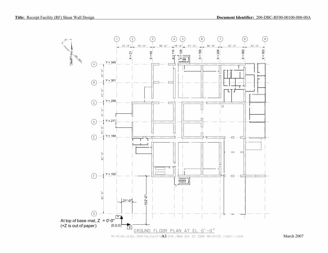
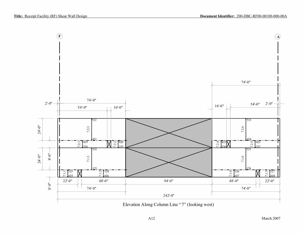
The plan, elevation and dimensions in Attachment A are used as the basis for the structural configuration of the Receipt Facility shear walls. These drawings are based on Plant Design engineering sketches, 200-P0K-MGR0-10301-000-00B (Ref.2.2.7), 200-P0K-MGR0-10401-000-00B (Ref.2.2.8), 200-P0K-MGR0-10501-000-00B (Ref.2.2.9), 200-P0K-MGR0-10601-000-00B (Ref.2.2.10), 200-P0K-MGR0-10701-000-00B (Ref.2.2.11), Receipt Facility (RF) Preliminary Layout Ground Floor Plan, Second Floor Plan, Third Floor Plan, Section A, and Section B, respectively. The wall length dimensions (including openings) are assumed as shown in Attachment A.
Rationale– The rationale for this assumption is that the drawings in Attachment A coincide with the members and dimensions used in 200-SYC-RF00-00400-000-00A, RF Seismic Analysis, (Ref.2.2.5). The forces from the seismic analysis calculation exactly correspond to Attachment A. The development of the general arrangements continues to be refined and the referenced sketches have been superseded; however the referenced sketches form the basis for the Tier 1 analysis and related design work; the major rooms and wall locations and sizes are not expected to change. Properties computed in this calculation are adequate for the current initial design and analysis work. Before the Tier-2 analysis and design efforts begin the configurations will be reviewed against the latest committed or confirmed drawings and revised as required
Where Used: Assumption is used in the entire calculation
3.2 ASSUMPTIONS NOT REQUIRING VERIFICATION 3.2.1 Receipt Facility Structure
The Receipt Facility behaves as a low-rise shear wall structure.
Rationale– The primary load path for lateral loads is through the roof and floor diaphragms to the supporting concrete walls. Then the concrete walls transfer the loads as in-plane shear loads to the mat foundation.
Where used: Assumption is used in the entire calculation
8 March 2007

Title: Receipt Facility (RF) Shear Wall Design Document Identifier: 200-DBC-RF00-00100-000-00A
4. METHODOLOGY
4.1 QUALITY ASSURANCE This calculation was prepared in accordance with EG-PRO-3DP-G04B-00037, Calculations and Analyses (Ref. 2.1.2). The RF has been classified as a structure that is Important to Safety, ITS, in section 6.1.2 of the Basis of Design for the TAD Canister-Based Repository Design Concept document (Ref.2.2.3). Therefore, this document is subject to the requirements of the BSC Quality Management Directive (Ref. 2.1.1, Section 2.1.C.1.1.a.i. and 17.E.) and the approved version will be designated as QA:QA.
4.2 USE OF SOFTWARE
Excel 2003 and Word 2003, which are part of the Microsoft Office 2003 suite of programs operated by Microsoft Windows XP, were used in this calculation. Microsoft Office 2003, as used in this calculation, is classified as Level 2 software usage as defined in IT-PRO-0011 (Ref. 2.1.3). Microsoft Office 2003 is listed on the current Controlled Software Report (SW Tracking Number 610236-2003-00). Microsoft Office Professional and Microsoft Windows XP are listed on the Repository Project Management Automation Plan (Ref. 2.1.4).
The software was executed on a PC system running the Microsoft Windows XP operating system. Word 2003 was used in the text preparation of this document; no calculation functions contained in Word 2003 were used in this document. Excel 2003 output was checked by visual inspection and hand calculations.
4.3 DESIGN METHOD This calculation uses the results of the RF Seismic Analysis calculation (Ref.2.2.5) to perform a preliminary design of the RF shear walls. Design of slabs (diaphragms) and the base slab are contained in separate calculations and are not addressed in this calculation. Shear wall plans and elevations are shown in Attachment A. These drawings were developed from the Plant design general arrangement sketches (Ref.2.2.7 thru Ref.2.2.11) The RF can be classified as a low rise shear wall structure (Assumption 3.2.1). The predominant load path for seismic loads is through the diaphragms and shear walls to the base slab. The Receipt Facility shear wall design complies with ACI 349 (Ref.2.2.2) requirements. The Receipt Facility shear walls are designed for the combined effects of in-plane shear loads, in-plane bending moments, out-of-plane shear loads, and out-of-plane bending moments. Also considered in the Receipt Facility shear wall design is shear friction, or the capacity of the wall to transfer horizontal loads into the base slab. The design procedure for the Receipt Facility shear walls is listed in Appendix D, Section D5, of the Seismic Analysis and Design Approach Document (Ref.2.2.4). A Microsoft Excel template based on this design procedure is also listed in Appendix D, Section D5.2,
9 March 2007
Title: Receipt Facility (RF) Shear Wall Design Document Identifier: 200-DBC-RF00-00100-000-00A
of the Seismic Analysis and Design Approach Document (Ref.2.2.4) and is used for the design of the Receipt Facility concrete shear walls.
5. LIST OF ATTACHMENTS Number of Pages
Attachment A Floor Plan and Wall Elevations 17 Attachment B Shear Wall Design Templates (North-South Walls) CD 1 of 1 Attachment C Shear Wall Design Templates (East-West Walls) CD 1 of 1 Attachment D Excel and Word files relevant to this calculation CD 1 of 1
6. BODY OF CALCULATION
6.1 SHEAR WALL DESIGN FORCES This calculation for the shear wall design of the Receipt Facility structure uses axial forces, shear forces, moments, and accelerations from a response spectrum seismic analysis, along with axial loads derived from a 1g vertical load case (Ref.2.2.5). As required in Section 6.3 of 200-SYC-RF00-00400-000-00A, RF Seismic Analysis, (Ref.2.2.5), these forces will be subjected to a torsional increase factor. This factor accounts for load eccentricity and increases the magnitude of the loads. The YMP shear wall template introduced in the Seismic Analysis and Design Approach Document (Ref.2.2.4) is used for the design of the Receipt Facility reinforced concrete shear walls. This template accepts axial loads with a certain sign convention. Positive values are taken as compression and negative values are taken as tension. The SAP 2000 output from 200-SYC-RF00-00400-000-00A, RF Seismic Analysis (Ref.2.2.5), uses the opposite sign convention where negative values are taken as compression and positive values are taken as tension. This change in sign is addressed in the Design Forces spreadsheet (Table 1). The results from 200-SYC-RF00-00400-000-00A, RF Seismic Analysis (Ref.2.2.5), state that the DBGM-2 (2000 year return period ground motion) 35’ upper bound alluvium soil case governs the design of the Receipt Facility structure. The values used in this design are taken directly from the analyses results of this soil case. Design forces are calculated for direct input into the YMP shear wall template. Axial force in tension, axial force in compression, in-plane shear, and in-plane moment are calculated. Figure 1 displays the axes of the loads as they are applied to a shear wall. Out-of-plane shear and out-of-plane moment are calculated using the YMP shear wall template (See Attachments B and C).
10 March 2007

Title: Receipt Facility (RF) Shear Wall Design Document Identifier: 200-DBC-RF00-00100-000-00A
FORCE IN+/- X DIRECTION: AXIAL FORCES = P or E (+Compression) FORCE IN +/- Y DIRECTION: IN-PLANE SHEAR FORCES = Vu FORCE IN +/- Z DIRECTION: OUT-OF-PLANE SHEAR FORCES = Vz MOMENTS ABOUT Z AXIS: IN-PLANE MOMENTS = Mz MOMENTS ABOUT Y AXIS: OUT-OF-PLANE MOMENTS = My
Wall length lw
+Y
+X+Z
+Y
+X+Z Wall thickness tw
Figure 1 Shear Wall Local Coordinate System
Note: Vz and My are calculated in the shear wall design templates (Attachments B & C)
Axial force in tension is taken as: Ft = −1*[(DL + 25%LL) + Et + Et * f ] (Eq.6.1.1)
Where: Ft = axial force in tension (kips) -1 represents the change in sign convention between SAP 2000 output and YMP shear
wall template DL+25%LL = axial force (kips) (compression) from 1g vertical load case (Ref.2.2.5) Et = axial force (kips) (tension) from DBGM-2 seismic analysis (Ref.2.2.5) f = torsional increase factor (%) (Ref.2.2.5) Referencing Attachment A and the results from 200-SYC-RF00-00400-000-00A RF Seismic Analysis (Ref.2.2.5) an example calculating the axial force in tension for member 2.1.1 is shown here:
Ft = -1*[(-920.52)+913.25+(913.25*24.49%)] = -216.41 kips (Using Eq.6.1.1)
Axial force in compression is taken as: Fc = −1*[(DL + 25%LL) + Ec + Ec * f ] (Eq.6.1.2)
11 March 2007

Title: Receipt Facility (RF) Shear Wall Design Document Identifier: 200-DBC-RF00-00100-000-00A
Where: Fc = axial force in compression (kips) -1 represents the change in sign convention between SAP 2000 output and YMP shear
wall template DL+25%LL = axial force (kips) (compression) from 1g vertical load case (Ref.2.2.5) Ec = axial force (kips) (compression) from DBGM-2 seismic analysis (Ref.2.2.5) f = torsional increase factor (%) (Ref.2.2.5) Referencing Attachment A and the results from 200-SYC-RF00-00400-000-00A RF Seismic Analysis (Ref.2.2.5) an example calculating the axial force in compression for member 2.1.1 is shown here:
Fc = -1*[(-920.52)+(-913.25)+(-913.25*24.49%)] = 2057.45 kips (Using Eq.6.1.2)
In-plane shear force is taken as: Vu = E1+ E1* f (Eq.6.1.3)
Where: Vu = in-plane shear force (kips) E1 = in-plane shear force (kips) from DBGM-2 seismic analysis (Ref.2.2.5) f = torsional increase factor (%) (Ref.2.2.5) Referencing Attachment A and the results from 200-SYC-RF00-00400-000-00A RF Seismic Analysis (Ref.2.2.5) an example calculating the axial force in compression for member 2.1.1 is shown here:
Vu = 1091.41+(1091.41*24.49%) = 1358.73 kips (Using Eq.6.1.3)
In-plane bending moment is taken as:
Mz = Mzo + Mzo * f (Eq.6.1.4)
Where: Mz = in-plane bending moment (kip-ft) Mzo = in-plane bending moment (kip-ft) from DBGM-2 seismic analysis (Ref.2.2.5) f = torsional increase factor (%) (Ref.2.2.5) Referencing Attachment A and the results from 200-SYC-RF00-00400-000-00A RF Seismic Analysis (Ref.2.2.5) an example calculating the axial force in compression for member 2.1.1 is shown here:
Mz = 17930.01+(17930.01*24.49%) = 22321.67 kip-ft (Using Eq.6.1.4) The resulting forces and moments acting in the shear walls are shown in Table 1.
12 March 2007

Title: Receipt Facility (RF) Shear Wall Design Document Identifier: 200-DBC-RF00-00100-000-00ATable 1 Shear Wall Design Forces
SHEAR WALL DESIGN INPUT (NORTH - SOUTH WALLS)
DBGM-2 Seismic Loads from SAP 2000 output
(Ref.2.2.5 Attachment D)
Dead & Live from SAP 2000 output
(Ref.2.2.5 Attachment D) Torsional Increase Factor (Ref.2.2.5
DESIGN FORCES WITH TORSIONAL INCREASE FACTOR for input into Shear Wall Design Template
Member Geometry (Ref.2.2.5 Table 1)
Member (Attachment A)
Table 4) Axial Force
(tension)
Axial Force (compression)
In-Plane Shear Force
In-Plane Moment
Axial Force (compression)
Axial Force (Tension)
Axial Force (Compression) In-Plane Shear In-Plane
Moment Thickness Height Length
Et Ec E1 Mzo DL + 25%LL f Ft = -1*[(DL+25%LL) + Et + Et*f]
Fc = -1*[(DL+25%LL) + Ec + Ec*f]
Vu = E1 + E1*f
Mz = Mzo + Mzo*f
tw h L
(kips) (kips) (kips) (kip-ft) (kips) % (kips) (kips) (kips) (kip-ft) (ft) (ft) (ft)
2.1.1 913.25 -913.25 1091.41 17930.01 -920.52 24.5% -216.41 2057.45 1358.73 22321.67 2 32 34.5 2.1.2 832.67 -832.67 951.96 15587.06 -823.32 24.5% -213.31 1859.94 1185.12 19404.85 2 32 31.5 2.2.1 935.77 -935.77 1784.17 30173.79 -993.22 18.5% -115.54 2101.98 2113.98 35751.62 2 32 78 3.1.1 4592.28 -4592.28 6342.38 52861.98 -4400.80 16.7% -960.45 9762.05 7404.40 61713.69 4 12 74 3.1.2 3163.78 -3163.78 5643.25 44362.65 -3706.31 16.7% 0.00 7399.86 6588.21 51791.14 4 12 66 3.1.3 4400.39 -4400.39 6342.38 52861.98 -3943.02 16.7% -1194.22 9080.25 7404.40 61713.69 4 12 74 3.1.4 10258.78 -10258.78 18328.01 391383.58 -12050.13 16.7% 0.00 24026.73 21397.02 456920.49 4 20 242 3.2.1 2030.93 -2030.93 3535.41 27242.67 -1988.50 12.5% -295.95 4272.95 3976.73 30643.36 4 12 74 3.2.2 3505.24 -3505.24 7700.29 107412.53 -3954.02 12.5% 0.00 7896.81 8661.51 120820.76 4 12 160 3.2.3 4988.57 -4988.57 11235.70 143086.52 -5942.52 12.5% 0.00 11553.80 12638.24 160947.91 4 20 242 3.3.1 1507.06 -1507.06 5606.27 119299.26 -1385.14 7.4% -233.95 3004.23 6023.00 128167.09 4 36 78 4.1.1 1537.66 -1537.66 1776.81 11092.27 -1345.53 8.5% -322.15 3013.22 1927.06 12030.23 4 12 22 4.1.2 2449.74 -2449.74 3828.73 26425.24 -2654.71 8.5% -2.18 5311.60 4152.49 28659.75 4 12 44 4.1.3 2882.07 -2882.07 5826.63 46620.30 -3882.30 8.5% 0.00 7008.08 6319.32 50562.48 4 12 66 4.1.4 3567.12 -3567.12 5465.03 42455.39 -3557.04 8.5% -311.71 7425.79 5927.15 46045.40 4 12 62 4.1.5 8463.24 -8463.24 16897.19 342790.53 -11439.58 8.5% 0.00 20618.47 18326.01 371776.72 4 20 242 4.2.1 1532.86 -1532.86 3250.30 42138.27 -1895.13 6.1% 0.00 3520.89 3447.31 44692.43 4 12 62 4.2.2 1532.86 -1532.86 3250.30 61887.61 -1895.13 6.1% 0.00 3520.89 3447.31 65638.85 4 20 86 4.2.3 1449.38 -1449.38 3538.09 55005.61 -1859.48 6.1% 0.00 3396.71 3752.55 58339.71 4 12 74 4.2.4 1449.38 -1449.38 3538.09 60357.38 -1859.48 6.1% 0.00 3396.71 3752.55 64015.87 4 20 86 5.1.1 2860.45 -2860.45 5645.45 101106.07 -4009.81 5.2% 0.00 7019.36 5939.72 106376.16 4 32 78 6.1.1 3268.45 -3268.45 5168.95 91899.15 -3914.11 2.2% 0.00 7253.66 5281.40 93898.48 4 32 74 6.1.2 450.19 -450.19 253.09 4088.61 -619.91 2.2% 0.00 1079.89 258.60 4177.56 4 32 12 6.1.3 679.44 -679.44 704.19 11422.52 -968.87 2.2% 0.00 1663.10 719.51 11671.02 4 32 19 6.1.4 609.54 -609.54 559.96 9070.72 -852.08 2.2% 0.00 1474.88 572.14 9268.06 4 32 17 6.1.5 3014.90 -3014.90 5168.95 91899.15 -3613.21 2.2% 0.00 6693.70 5281.40 93898.48 4 32 74 6.2.1 1425.68 -1425.68 3117.64 52577.62 -1813.40 2.2% 0.00 3270.08 3185.45 53721.16 4 32 74 6.2.2 1314.59 -1314.59 3117.64 52577.62 -1656.73 2.2% 0.00 2999.91 3185.45 53721.16 4 32 74 6.3.1 1211.79 -1211.79 4258.34 94196.10 -1654.70 2.2% 0.00 2893.39 4352.87 96287.06 4 40 78 6.3.2 1390.92 -1390.92 4729.09 80502.66 -1369.90 7.4% -123.79 2863.59 5078.50 86450.54 4 28 78 7.1.1 2003.45 -2003.45 1512.08 7898.17 -1251.09 9.1% -935.56 3437.73 1650.34 8620.35 4 8 22 7.1.2 1953.40 -1953.40 3420.61 32901.98 -2569.05 9.1% 0.00 4701.07 3733.38 35910.44 4 8 48 7.1.3 3367.49 -3367.49 4932.70 70483.66 -3820.14 9.1% 0.00 7495.54 5383.73 76928.49 4 24 74 7.1.4 1795.84 -1795.84 3420.69 32885.79 -2397.15 9.1% 0.00 4357.20 3733.47 35892.78 4 8 48 7.1.5 1921.61 -1921.61 1512.12 7897.14 -1127.04 9.1% -970.28 3224.36 1650.38 8619.24 4 8 22 7.1.6 3077.14 -3077.14 4932.81 70482.26 -3524.19 9.1% 0.00 6882.70 5383.85 76926.96 4 24 74 7.2.1 1400.60 -1400.60 2357.61 24844.39 -1334.68 7.6% -171.99 2841.35 2536.16 26725.91 4 8 54 7.2.2 554.09 -554.09 646.46 2986.68 -414.07 7.6% -181.98 1010.12 695.41 3212.87 4 8 16 7.2.3 1436.77 -1436.77 3004.07 45747.17 -1748.75 7.6% 0.00 3294.34 3231.57 49211.72 4 24 74 7.2.4 539.27 -539.27 646.48 2986.47 -388.70 7.6% -191.41 968.80 695.43 3212.64 4 8 16 7.2.5 1352.19 -1352.19 2357.68 24836.33 -1205.19 7.6% -249.41 2659.78 2536.23 26717.24 4 8 54 7.2.6 1349.58 -1349.58 3004.15 45734.31 -1593.88 7.6% 0.00 3045.66 3231.67 49197.88 4 24 74 8.1.1 8955.91 -8955.91 13575.95 318021.46 -9586.59 18.6% -1032.73 20205.91 16097.46 377088.66 4 8 186 8.1.2 2742.72 -2742.72 2880.45 14132.89 -2206.22 18.6% -1045.92 5458.35 3415.45 16757.84 4 8 40 8.1.3 10656.72 -10656.72 16456.41 437040.13 -11792.81 18.6% -843.22 24428.83 19512.91 518213.07 4 24 242 8.2.1 1588.52 -1588.52 2996.76 50564.02 -1721.47 14.9% -103.40 3546.34 3442.63 58087.17 4 32 74 8.2.2 1531.68 -1531.68 2996.76 50564.02 -1564.80 14.9% -194.77 3324.38 3442.63 58087.17 4 32 74 8.3.1 1299.76 -1299.76 3462.65 78225.08 -1393.25 0.9% 0.00 2704.95 3494.48 78944.03 4 40 78 9.1.1 2063.93 -2063.93 2487.02 45114.19 -1913.75 26.3% -693.44 4520.95 3141.64 56989.03 2 32 78
13
March 2007
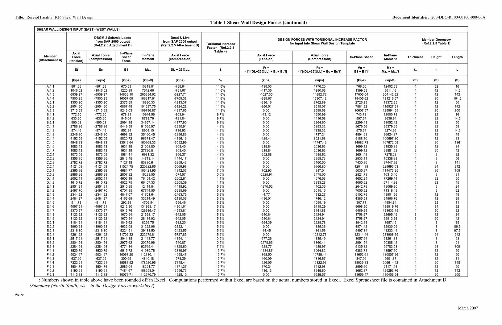
Title: Receipt Facility (RF) Shear Wall Design Document Identifier: 200-DBC-RF00-00100-000-00ATable 1 Shear Wall Design Forces (continued)
SHEAR WALL DESIGN INPUT (EAST - WEST WALLS)
DBGM-2 Seismic Loads from SAP 2000 output
(Ref.2.2.5 Attachment D)
Dead & Live from SAP 2000 output
(Ref.2.2.5 Attachment D) Torsional Increase Factor (Ref.2.2.5
DESIGN FORCES WITH TORSIONAL INCREASE FACTOR for input into Shear Wall Design Template
Member Geometry (Ref.2.2.5 Table 1)
Member (Attachment A)
Table 4) Axial Force
(tension)
Axial Force (compression)
In-Plane Shear Force
In-Plane Moment
Axial Force (compression)
Axial Force (Tension)
Axial Force (Compression) In-Plane Shear In-Plane
Moment Thickness Height Length
Et Ec E1 Mzo DL + 25%LL f Ft = -1*[(DL+25%LL) + Et + Et*f]
Fc = -1*[(DL+25%LL) + Ec + Ec*f]
Vu = E1 + E1*f
Mz = Mzo + Mzo*f
tw h L
(kips) (kips) (kips) (kip-ft) (kips) % (kips) (kips) (kips) (kip-ft) (ft) (ft) (ft)
A.1.1 861.38 -861.38 670.53 10819.81 -788.84 14.6% -198.53 1776.20 768.60 12402.33 4 32 16 A.1.2 1046.02 -1046.02 1220.99 7512.66 -781.67 14.6% -417.35 1980.68 1399.58 8611.48 4 12 14.5 A.1.3 6939.97 -6939.97 14836.10 265334.62 -6927.71 14.6% -1027.30 14882.72 17006.04 304142.82 4 12 142 A.1.4 7500.95 -7500.95 16057.09 166817.61 -7709.38 14.6% -888.67 16307.42 18405.62 191216.57 4 20 164.5 A.2.1 1350.20 -1350.20 2375.55 16880.33 -1213.37 14.8% -336.16 2762.89 2726.25 19372.35 4 12 50 A.2.2 2954.60 -2954.60 6867.48 101537.75 -3124.28 14.8% -266.51 6515.07 7881.32 116527.61 4 12 142 A.2.3 3713.69 -3713.69 9243.03 109786.87 -4337.65 14.8% 0.00 8599.58 10607.57 125994.55 4 20 200 B.1.1 772.50 -772.50 678.31 10944.56 -803.94 9.7% -43.12 1650.99 743.78 12000.78 4 32 16 B.1.2 633.60 -633.60 545.04 8788.76 -721.84 9.7% 0.00 1416.58 597.64 9636.94 4 32 14.5 B.2.1 990.03 -990.03 2094.88 34667.14 -1177.90 9.8% 0.00 2264.60 2299.43 38052.12 4 32 50 C.1.1 2786.36 -2786.36 5449.59 91565.97 -2990.91 4.2% 0.00 5893.32 5676.56 95379.65 4 32 58 C.1.2 574.46 -574.46 552.24 8904.10 -736.93 4.2% 0.00 1335.32 575.24 9274.96 4 32 14.5 C.1.3 2246.80 -2246.80 4698.92 35160.45 -2396.86 4.2% 0.00 4737.24 4894.63 36624.87 4 12 45 C.1.4 4152.59 -4152.59 8820.72 96671.47 -4196.13 4.2% -129.41 8521.68 9188.10 100697.80 4 12 83 C.1.5 4948.33 -4948.33 13519.64 160968.33 -6592.99 4.2% 0.00 11747.42 14082.73 167672.59 4 20 136 C.1.6 1083.13 -1083.13 1631.19 21058.80 -908.40 4.2% -219.84 2036.63 1699.12 21935.89 2 12 34 C.1.7 1083.13 -1083.13 1631.19 27726.81 -908.40 4.2% -219.84 2036.63 1699.12 28881.62 2 20 42 C.2.1 1073.59 -1073.59 1584.11 6981.32 -866.37 4.3% -252.88 1985.62 1651.48 7278.23 4 8 32 C.2.2 1356.85 -1356.85 2813.45 14713.14 -1444.17 4.3% 0.00 2858.73 2933.11 15338.88 4 8 56 C.2.3 2782.72 -2782.72 7127.18 83880.61 -3259.43 4.3% 0.00 6160.50 7430.30 87447.99 4 8 141 C.2.4 4121.58 -4121.58 11524.75 220322.86 -5569.98 4.3% 0.00 9866.85 12014.89 229693.03 4 24 242 C.3.1 2365.99 -2365.99 4681.77 106421.95 -1842.06 7.6% -702.93 4387.04 5035.97 114473.25 4 36 109 C.3.2 2886.28 -2886.28 2807.92 16233.55 -574.57 0.5% -2325.91 3475.05 2821.73 16313.40 4 8 91 D.1.1 2052.11 -2052.11 4603.19 76454.42 -2602.61 1.1% 0.00 4676.58 4652.24 77269.14 4 32 50 D.1.2 1610.72 -1610.72 4022.75 66407.33 -2305.39 1.1% 0.00 3933.28 4065.62 67114.99 4 32 45 E.1.1 2551.81 -2551.81 2510.35 12414.84 -1415.92 5.3% -1270.52 4102.36 2642.79 13069.80 4 8 24 E.1.2 2497.70 -2497.70 6701.95 67744.55 -3385.69 5.3% 0.00 6015.16 7055.52 71318.49 4 8 62 E.1.3 2344.82 -2344.82 4847.07 41701.64 -2463.75 5.3% -4.77 4932.27 5102.78 43901.66 4 12 45 E.1.4 2484.97 -2484.97 4166.69 33214.49 -2130.06 5.3% -486.01 4746.12 4386.51 34966.76 4 12 39 E.1.5 511.73 -511.73 292.29 4706.54 -556.46 5.3% 0.00 1095.19 307.71 4954.84 4 32 11 E.1.6 4097.51 -4097.51 9212.30 131863.17 -4801.61 5.3% 0.00 9115.29 9698.30 138819.76 4 24 92 E.1.7 3370.27 -3370.27 9013.76 126936.47 -4593.81 5.3% 0.00 8141.88 9489.29 133633.15 4 20 92 E.1.8 1123.62 -1123.62 1670.54 21558.17 -942.05 5.3% -240.84 2124.94 1758.67 22695.49 2 12 34 E.1.9 1123.62 -1123.62 1670.54 28414.92 -942.05 5.3% -240.84 2124.94 1758.67 29913.98 2 20 42 E.2.1 1184.61 -1184.61 1845.62 8226.75 -982.20 5.2% -264.39 2228.78 1942.18 8657.15 4 8 35 E.2.2 1960.68 -1960.68 4632.08 31292.96 -2322.11 5.2% 0.00 4385.36 4874.42 32930.09 4 8 86.5 E.2.3 2316.80 -2316.80 5224.51 39183.50 -2423.55 5.2% -14.45 4861.56 5497.84 41233.44 4 8 97.5 E.2.4 4261.92 -4261.92 11702.22 222279.81 -5727.85 5.2% 0.00 10212.73 12314.44 233908.69 4 24 242 E.3.1 2517.91 -2517.91 3041.38 21148.77 -1854.11 0.5% -677.26 4385.49 3057.64 21261.88 4 8 93 E.3.2 2804.54 -2804.54 2975.62 20279.96 -540.87 0.5% -2278.66 3360.41 2991.54 20388.42 4 8 91 E.3.3 2284.54 -2284.54 4774.14 92765.41 -1828.60 7.6% -628.77 4285.97 5135.32 99783.53 4 28 109 F.1.1 3520.79 -3520.79 5515.72 41989.76 -2889.97 15.7% -1184.87 6964.82 6383.71 48597.60 4 12 50 F.1.2 5034.67 -5034.67 10068.20 112330.11 -4958.47 15.7% -868.50 10785.44 11652.61 130007.26 4 12 90 F.1.3 637.99 -637.99 300.65 4840.18 -578.29 15.7% -160.09 1316.67 347.96 5601.87 4 32 11 F.1.4 7322.21 -7322.21 15583.92 178520.96 -7848.44 15.7% -626.05 16322.93 18036.33 206614.42 4 20 148 F.2.1 1504.74 -1504.74 2589.04 18291.77 -1371.37 15.7% -370.24 3112.98 2996.60 21171.18 4 12 50 F.2.2 3190.61 -3190.61 7484.67 108253.04 -3556.73 15.7% -136.13 7249.60 8662.87 125293.76 4 12 142 F.2.3 4113.88 -4113.88 10073.71 112670.79 -4928.10 15.7% 0.00 9689.57 11659.47 130406.94 4 20 200
Note
: Numbers shown in table above have been rounded off in Excel. Computations performed within Excel are based on the actual numbers stored in Excel. Excel Spreadsheet file is contained in Attachment D (Summary (North-South).xls – in the Design Forces worksheet)
14
March 2007
Title: Receipt Facility (RF) Shear Wall Design Document Identifier: 200-DBC-RF00-00100-000-00A
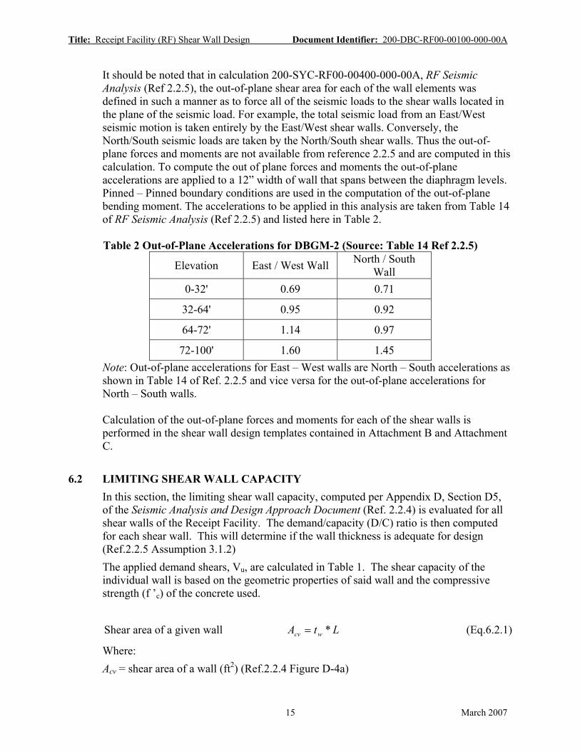
It should be noted that in calculation 200-SYC-RF00-00400-000-00A, RF Seismic Analysis (Ref 2.2.5), the out-of-plane shear area for each of the wall elements was defined in such a manner as to force all of the seismic loads to the shear walls located in the plane of the seismic load. For example, the total seismic load from an East/West seismic motion is taken entirely by the East/West shear walls. Conversely, the North/South seismic loads are taken by the North/South shear walls. Thus the out-of-plane forces and moments are not available from reference 2.2.5 and are computed in this calculation. To compute the out of plane forces and moments the out-of-plane accelerations are applied to a 12” width of wall that spans between the diaphragm levels. Pinned – Pinned boundary conditions are used in the computation of the out-of-plane bending moment. The accelerations to be applied in this analysis are taken from Table 14 of RF Seismic Analysis (Ref 2.2.5) and listed here in Table 2.
Table 2 Out-of-Plane Accelerations for DBGM-2 (Source: Table 14 Ref 2.2.5)
Elevation East / West Wall North / South Wall
0-32' 0.69 0.71
32-64' 0.95 0.92
64-72' 1.14 0.97
72-100' 1.60 1.45 Note: Out-of-plane accelerations for East – West walls are North – South accelerations as shown in Table 14 of Ref. 2.2.5 and vice versa for the out-of-plane accelerations for North – South walls.
Calculation of the out-of-plane forces and moments for each of the shear walls is performed in the shear wall design templates contained in Attachment B and Attachment C.
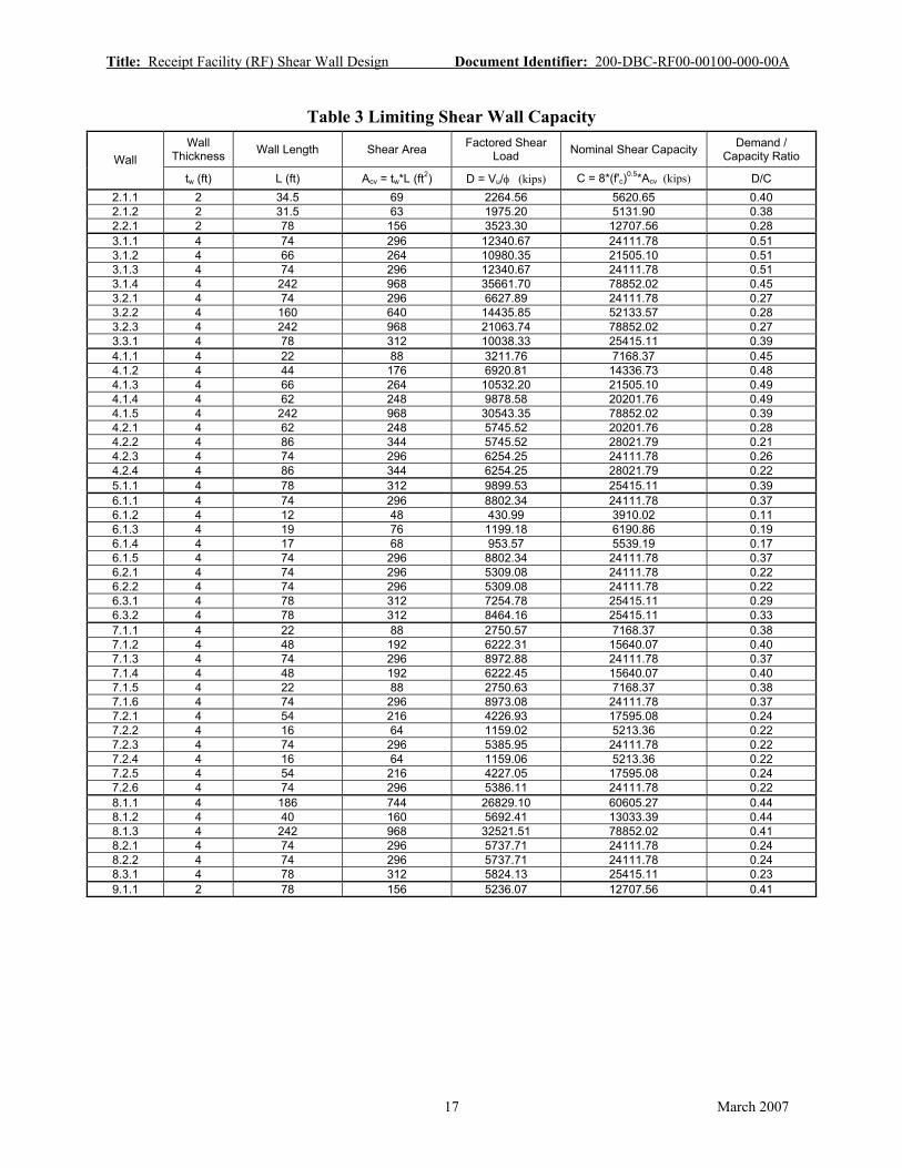
6.2 LIMITING SHEAR WALL CAPACITY In this section, the limiting shear wall capacity, computed per Appendix D, Section D5, of the Seismic Analysis and Design Approach Document (Ref. 2.2.4) is evaluated for all shear walls of the Receipt Facility. The demand/capacity (D/C) ratio is then computed for each shear wall. This will determine if the wall thickness is adequate for design (Ref.2.2.5 Assumption 3.1.2) The applied demand shears, Vu, are calculated in Table 1. The shear capacity of the individual wall is based on the geometric properties of said wall and the compressive strength (f ’c) of the concrete used.
Shear area of a given wall Acv = tw * L (Eq.6.2.1)
Where: Acv = shear area of a wall (ft2) (Ref.2.2.4 Figure D-4a)
15 March 2007

Title: Receipt Facility (RF) Shear Wall Design Document Identifier: 200-DBC-RF00-00100-000-00A
tw = wall thickness (ft) (Table 1) L = length of wall (ft) (Table 1) Referencing Attachment A and the results from 200-SYC-RF00-00400-000-00A RF Seismic Analysis (Ref.2.2.5) an example calculating the shear area of member 2.1.1 is shown here:
Acv = 2*34.5 = 69 ft2 (Using Eq.6.2.1)
Shear capacity of a given wall Capacity = C = 8* f ' c * Acv (Eq.6.2.2)
Where: C = Vn max (Ref.2.2.4 Section D5.1.1 Step 1) Acv = shear area of a wall (ft2) (Ref.2.2.4 Figure D-4a) f’c = concrete compressive strength = 5000 psi Referencing Attachment A and the results from 200-SYC-RF00-00400-000-00A RF Seismic Analysis (Ref.2.2.5) an example calculating the shear capacity of member 2.1.1 is shown here:
C = 8* 5000 * (144 /1000) *69 = 5620.65 kips (Using Eq.6.2.2)
According to Appendix D5 of the Seismic Analysis and Design Approach Document (Ref.2.2.4) the strength reduction factor, φ, is taken as 0.60 for in-plane shear. This method in which the strength reduction factor is used is shown here:
Factored in-plane shear load Demand = D = Vu/φ (Eq.6.2.3) Where: D = Factored Shear Load (Ref.2.2.4 Figure D-4a) Vu = in-plane shear force (kips) (Table 1)
φ = strength reduction factor = 0.6 Referencing Attachment A and the results from 200-SYC-RF00-00400-000-00A RF Seismic Analysis (Ref.2.2.5) an example calculating the factored in-plane shear of member 2.1.1 is shown here:
D = 1358.73/0.6 = 2264.6 kips (Using Eq.6.2.3) To determine if the wall thickness is adequate, a demand/capacity ratio is calculated. The values calculated using equations 6.2.1, 6.2.2, and 6.2.3 are shown in Table 3.
16 March 2007
Title: Receipt Facility (RF) Shear Wall Design Document Identifier: 200-DBC-RF00-00100-000-00A
Table 3 Limiting Shear Wall Capacity
Wall Wall
Thickness Wall Length Shear Area Factored Shear Load Nominal Shear Capacity Demand /
Capacity Ratio
tw (ft) L (ft) Acv = tw*L (ft2) D = Vu/φ (kips) C = 8*(f'c)0.5*Acv (kips) D/C 2.1.1 2 34.5 69 2264.56 5620.65 0.40 2.1.2 2 31.5 63 1975.20 5131.90 0.38 2.2.1 2 78 156 3523.30 12707.56 0.28 3.1.1 4 74 296 12340.67 24111.78 0.51 3.1.2 4 66 264 10980.35 21505.10 0.51 3.1.3 4 74 296 12340.67 24111.78 0.51 3.1.4 4 242 968 35661.70 78852.02 0.45 3.2.1 4 74 296 6627.89 24111.78 0.27 3.2.2 4 160 640 14435.85 52133.57 0.28 3.2.3 4 242 968 21063.74 78852.02 0.27 3.3.1 4 78 312 10038.33 25415.11 0.39 4.1.1 4 22 88 3211.76 7168.37 0.45 4.1.2 4 44 176 6920.81 14336.73 0.48 4.1.3 4 66 264 10532.20 21505.10 0.49 4.1.4 4 62 248 9878.58 20201.76 0.49 4.1.5 4 242 968 30543.35 78852.02 0.39 4.2.1 4 62 248 5745.52 20201.76 0.28 4.2.2 4 86 344 5745.52 28021.79 0.21 4.2.3 4 74 296 6254.25 24111.78 0.26 4.2.4 4 86 344 6254.25 28021.79 0.22 5.1.1 4 78 312 9899.53 25415.11 0.39 6.1.1 4 74 296 8802.34 24111.78 0.37 6.1.2 4 12 48 430.99 3910.02 0.11 6.1.3 4 19 76 1199.18 6190.86 0.19 6.1.4 4 17 68 953.57 5539.19 0.17 6.1.5 4 74 296 8802.34 24111.78 0.37 6.2.1 4 74 296 5309.08 24111.78 0.22 6.2.2 4 74 296 5309.08 24111.78 0.22 6.3.1 4 78 312 7254.78 25415.11 0.29 6.3.2 4 78 312 8464.16 25415.11 0.33 7.1.1 4 22 88 2750.57 7168.37 0.38 7.1.2 4 48 192 6222.31 15640.07 0.40 7.1.3 4 74 296 8972.88 24111.78 0.37 7.1.4 4 48 192 6222.45 15640.07 0.40 7.1.5 4 22 88 2750.63 7168.37 0.38 7.1.6 4 74 296 8973.08 24111.78 0.37 7.2.1 4 54 216 4226.93 17595.08 0.24 7.2.2 4 16 64 1159.02 5213.36 0.22 7.2.3 4 74 296 5385.95 24111.78 0.22 7.2.4 4 16 64 1159.06 5213.36 0.22 7.2.5 4 54 216 4227.05 17595.08 0.24 7.2.6 4 74 296 5386.11 24111.78 0.22 8.1.1 4 186 744 26829.10 60605.27 0.44 8.1.2 4 40 160 5692.41 13033.39 0.44 8.1.3 4 242 968 32521.51 78852.02 0.41 8.2.1 4 74 296 5737.71 24111.78 0.24 8.2.2 4 74 296 5737.71 24111.78 0.24 8.3.1 4 78 312 5824.13 25415.11 0.23 9.1.1 2 78 156 5236.07 12707.56 0.41
17 March 2007
Title: Receipt Facility (RF) Shear Wall Design Document Identifier: 200-DBC-RF00-00100-000-00A
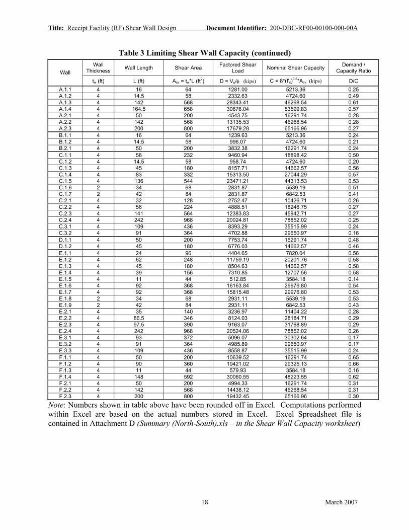
Table 3 Limiting Shear Wall Capacity (continued)
Wall Wall
Thickness Wall Length Shear Area Factored Shear Load Nominal Shear Capacity Demand /
Capacity Ratio
tw (ft) L (ft) Acv = tw*L (ft2) D = Vu/φ (kips) C = 8*(f'c)0.5*Acv (kips) D/C A.1.1 4 16 64 1281.00 5213.36 0.25 A.1.2 4 14.5 58 2332.63 4724.60 0.49 A.1.3 4 142 568 28343.41 46268.54 0.61 A.1.4 4 164.5 658 30676.04 53599.83 0.57 A.2.1 4 50 200 4543.75 16291.74 0.28 A.2.2 4 142 568 13135.53 46268.54 0.28 A.2.3 4 200 800 17679.28 65166.96 0.27 B.1.1 4 16 64 1239.63 5213.36 0.24 B.1.2 4 14.5 58 996.07 4724.60 0.21 B.2.1 4 50 200 3832.38 16291.74 0.24 C.1.1 4 58 232 9460.94 18898.42 0.50 C.1.2 4 14.5 58 958.74 4724.60 0.20 C.1.3 4 45 180 8157.71 14662.57 0.56 C.1.4 4 83 332 15313.50 27044.29 0.57 C.1.5 4 136 544 23471.21 44313.53 0.53 C.1.6 2 34 68 2831.87 5539.19 0.51 C.1.7 2 42 84 2831.87 6842.53 0.41 C.2.1 4 32 128 2752.47 10426.71 0.26 C.2.2 4 56 224 4888.51 18246.75 0.27 C.2.3 4 141 564 12383.83 45942.71 0.27 C.2.4 4 242 968 20024.81 78852.02 0.25 C.3.1 4 109 436 8393.29 35515.99 0.24 C.3.2 4 91 364 4702.88 29650.97 0.16 D.1.1 4 50 200 7753.74 16291.74 0.48 D.1.2 4 45 180 6776.03 14662.57 0.46 E.1.1 4 24 96 4404.65 7820.04 0.56 E.1.2 4 62 248 11759.19 20201.76 0.58 E.1.3 4 45 180 8504.63 14662.57 0.58 E.1.4 4 39 156 7310.85 12707.56 0.58 E.1.5 4 11 44 512.85 3584.18 0.14 E.1.6 4 92 368 16163.84 29976.80 0.54 E.1.7 4 92 368 15815.48 29976.80 0.53 E.1.8 2 34 68 2931.11 5539.19 0.53 E.1.9 2 42 84 2931.11 6842.53 0.43 E.2.1 4 35 140 3236.97 11404.22 0.28 E.2.2 4 86.5 346 8124.03 28184.71 0.29 E.2.3 4 97.5 390 9163.07 31768.89 0.29 E.2.4 4 242 968 20524.06 78852.02 0.26 E.3.1 4 93 372 5096.07 30302.64 0.17 E.3.2 4 91 364 4985.89 29650.97 0.17 E.3.3 4 109 436 8558.87 35515.99 0.24 F.1.1 4 50 200 10639.52 16291.74 0.65 F.1.2 4 90 360 19421.02 29325.13 0.66 F.1.3 4 11 44 579.93 3584.18 0.16 F.1.4 4 148 592 30060.55 48223.55 0.62 F.2.1 4 50 200 4994.33 16291.74 0.31 F.2.2 4 142 568 14438.12 46268.54 0.31 F.2.3 4 200 800 19432.45 65166.96 0.30
Note: Numbers shown in table above have been rounded off in Excel. Computations performed within Excel are based on the actual numbers stored in Excel. Excel Spreadsheet file is contained in Attachment D (Summary (North-South).xls – in the Shear Wall Capacity worksheet)
18 March 2007

Title: Receipt Facility (RF) Shear Wall Design Document Identifier: 200-DBC-RF00-00100-000-00A
6.3 SHEAR WALL DESIGN The results from Table 3 show that the wall thickness for each of the walls of the Receipt Facility is adequate. In this section, the reinforcing steel requirements are computed for all Receipt Facility shear walls. Reinforcing steel requirements need to satisfy the ACI 349-01 (Ref.2.2.2) Chapter 9, 11, and 21 requirements. To assist in performing the design, a procedure can be found in Steps 2 and 3 in Section D5 of Appendix D of the Seismic Analysis and Design Approach Document (Ref. 2.2.4). The YMP shear wall design template is also found in Appendix D of the Seismic Analysis and Design Approach Document (Ref.2.2.4). Shear wall templates for North-South walls can be found in Attachment B of this calculation. Shear wall templates for East-West walls can be found in Attachment C of this calculation. A summary of the reinforcement selections for each wall member can be found in Table 4. Demand / Capacity ratios for shear on gross section, in-plane shear, out-of-plane shear, and bending and axial loads are also summarized in Table 4.
19 March 2007

Title: Receipt Facility (RF) Shear Wall Design Document Identifier: 200-DBC-RF00-00100-000-00A
7 RESULTS AND CONCLUSIONS
7.1 RESULTS
Results from Table 3 indicate that the wall thickness for all of the RF shear walls satisfies the limiting shear wall requirements defined in ACI 349-01 (Ref.2.2.2) and presented for the YMP in Appendix D of the Seismic Analysis and Design Approach Document (Ref. 2.2.4). Furthermore, it is observed that all of the RF shear walls have a significant reserve margin available. This reserve capacity will be important in future fragility analysis calculations made for the RF structure.
The reinforcing steel requirements for each of the shear walls are computed using the YMP shear wall template (Ref.2.2.4) and displayed in Table 4. A representative wall pier is selected for each wall or wall elevation. The reinforcement patterns for the representative wall piers envelope the reinforcing required by the wall or wall elevation represented. See Attachment A for wall pier locations. Table 4 also displays the demand/capacity ratio for shear on gross section, in-plane shear, out of plane shear, and bending and axial loads. For all Receipt Facility shear walls, boundary elements are not required. (See Attachments B and C)
20 March 2007

1-#9@12"c/c EF 1-#9@12"c/c EF 0.40 0.38 0.11 0.55
1-#9@12"c/c EF 1-#9@12"c/c EF 0.28 0.26 0.14 0.39
3.1.2 1-#11@12"c/c EF 1-#11@12"c/c EF 0.51 0.56 0.11 0.25 3.1.3 1-#11@12"c/c EF 1-#11@12"c/c EF 0.51 0.57 0.11 0.25 3.1.4 1-#11@12"c/c EF 1-#11@12"c/c EF 0.45 0.50 0.11 0.20
1-#11@12"c/c EF 1-#11@12"c/c EF 0.27 0.30 0.14 0.25 1-#11@12"c/c EF 1-#11@12"c/c EF 0.28 0.31 0.14 0.25 1-#11@12"c/c EF 1-#11@12"c/c EF 0.27 0.30 0.14 0.25
1-#11@12"c/c EF 1-#11@12"c/c EF 0.48 0.53 0.11 0.29 1-#11@12"c/c EF 1-#11@12"c/c EF 0.49 0.54 0.11 0.24 1-#11@12"c/c EF 1-#11@12"c/c EF 0.49 0.54 0.11 0.25 1-#11@12"c/c EF 1-#11@12"c/c EF 0.39 0.43 0.11 0.19
1-#9@12"c/c EF 1-#9@12"c/c EF 0.21 0.29 0.14 0.39 1-#9@12"c/c EF 1-#9@12"c/c EF 0.26 0.37 0.14 0.40 1-#9@12"c/c EF 1-#9@12"c/c EF 0.22 0.32 0.14 0.39
1-#11@12"c/c EF 1-#11@12"c/c EF 0.37 0.40 0.11 0.32 1-#11@12"c/c EF 1-#11@12"c/c EF 0.11 0.14 0.11 0.47
1-#11@12"c/c EF 1-#11@12"c/c EF 0.17 0.20 0.11 0.51 1-#11@12"c/c EF 1-#11@12"c/c EF 0.37 0.40 0.11 0.31 1-#9@12"c/c EF 1-#9@12"c/c EF 0.22 0.32 0.14 0.39 1-#9@12"c/c EF 1-#9@12"c/c EF 0.22 0.32 0.14 0.39
1-#9@12"c/c EF 1-#9@12"c/c EF 0.33 0.48 0.19 0.52
1-#11@12"c/c EF 1-#11@12"c/c EF 0.38 0.44 0.11 0.40 1-#11@12"c/c EF 1-#11@12"c/c EF 0.40 0.44 0.11 0.30 1-#11@12"c/c EF 1-#11@12"c/c EF 0.37 0.41 0.11 0.28 1-#11@12"c/c EF 1-#11@12"c/c EF 0.40 0.44 0.11 0.30
1-#11@12"c/c EF 1-#11@12"c/c EF 0.37 0.41 0.11 0.28 1-#9@12"c/c EF 1-#9@12"c/c EF 0.24 0.35 0.14 0.39 1-#9@12"c/c EF 1-#9@12"c/c EF 0.22 0.32 0.14 0.47 1-#9@12"c/c EF 1-#9@12"c/c EF 0.22 0.32 0.14 0.39
1-#9@12"c/c EF 1-#9@12"c/c EF 0.24 0.35 0.14 0.39 1-#9@12"c/c EF 1-#9@12"c/c EF 0.22 0.32 0.14 0.39
1-#11@12"c/c EF 1-#11@12"c/c EF 0.44 0.49 0.11 0.24
1-#11@12"c/c EF 1-#11@12"c/c EF 0.41 0.46 0.11 0.21 1-#9@12"c/c EF 1-#9@12"c/c EF 0.24 0.34 0.14 0.40 1-#9@12"c/c EF 1-#9@12"c/c EF 0.24 0.34 0.14 0.41
Title: Receipt Facility (RF) Shear Wall Design Document Identifier: 200-DBC-RF00-00100-000-00A
Table 4 Shear Wall Design Summary
Wall Horizontal Reinforcing Vertical Reinforcing
Demand / Capacity Ratios Shear on Gross
Section In-Plane Shear Out-of-Plane Shear
Bending and Axial Loads
2.1.1 2.1.2 1-#9@12"c/c EF 1-#9@12"c/c EF 0.38 0.36 0.11 0.57 2.2.1 3.1.1 1-#11@12"c/c EF 1-#11@12"c/c EF 0.51 0.57 0.11 0.25
3.2.1 3.2.2 3.2.3 3.3.1 1-#11@12"c/c EF 1-#11@12"c/c EF 0.39 0.44 0.25 0.53 4.1.1 1-#11@12"c/c EF 1-#11@12"c/c EF 0.45 0.50 0.11 0.44 4.1.2 4.1.3 4.1.4 4.1.5 4.2.1 1-#9@12"c/c EF 1-#9@12"c/c EF 0.28 0.41 0.14 0.42 4.2.2 4.2.3 4.2.4 5.1.1 1-#11@12"c/c EF 1-#11@12"c/c EF 0.39 0.43 0.11 0.32 6.1.1 6.1.2 6.1.3 1-#11@12"c/c EF 1-#11@12"c/c EF 0.19 0.21 0.11 0.51 6.1.4 6.1.5 6.2.1 6.2.2 6.3.1 1-#9@12"c/c EF 1-#9@12"c/c EF 0.29 0.41 0.18 0.65 6.3.2 7.1.1 7.1.2 7.1.3 7.1.4 7.1.5 1-#11@12"c/c EF 1-#11@12"c/c EF 0.38 0.44 0.11 0.40 7.1.6 7.2.1 7.2.2 7.2.3 7.2.4 1-#9@12"c/c EF 1-#9@12"c/c EF 0.22 0.32 0.14 0.47 7.2.5 7.2.6 8.1.1 8.1.2 1-#11@12"c/c EF 1-#11@12"c/c EF 0.44 0.49 0.11 0.25 8.1.3 8.2.1 8.2.2 8.3.1 1-#9@12"c/c EF 1-#9@12"c/c EF 0.23 0.33 0.18 0.65 9.1.1 1-#9@12"c/c EF 1-#9@12"c/c EF 0.41 0.39 0.11 0.36
21 March 2007

1-#11@12"c/c EF 1-#11@12"c/c EF 0.49 0.56 0.10 0.72 1-#11@12"c/c EF 1-#11@12"c/c EF 0.61 0.68 0.10 0.29 1-#11@12"c/c EF 1-#11@12"c/c EF 0.57 0.64 0.10 0.19 1-#9@12"c/c EF 1-#9@12"c/c EF 0.28 0.40 0.14 0.40
1-#9@12"c/c EF 1-#9@12"c/c EF 0.27 0.39 0.14 0.40
1-#11@12"c/c EF 1-#11@12"c/c EF 0.21 0.26 0.10 0.68
1-#11@12"c/c EF 1-#11@12"c/c EF 0.50 0.55 0.10 0.46
1-#11@12"c/c EF 1-#11@12"c/c EF 0.56 0.62 0.10 0.33 1-#11@12"c/c EF 1-#11@12"c/c EF 0.57 0.63 0.10 0.28 1-#11@12"c/c EF 1-#11@12"c/c EF 0.53 0.59 0.10 0.21 1-#11@12"c/c EF 1-#11@12"c/c EF 0.51 0.35 0.10 0.36 1-#11@12"c/c EF 1-#11@12"c/c EF 0.41 0.28 0.10 0.32 1-#9@12"c/c EF 1-#11@12"c/c EF 0.26 0.38 0.14 0.26 1-#9@12"c/c EF 1-#11@12"c/c EF 0.27 0.38 0.14 0.26 1-#9@12"c/c EF 1-#11@12"c/c EF 0.27 0.39 0.14 0.26 1-#9@12"c/c EF 1-#11@12"c/c EF 0.25 0.36 0.14 0.26
1-#9@12"c/c EF 1-#11@12"c/c EF 0.16 0.23 0.04 0.04
1-#11@12"c/c EF 1-#11@12"c/c EF 0.48 0.53 0.10 0.49
1-#11@12"c/c EF 1-#11@12"c/c EF 0.56 0.65 0.10 0.51 1-#11@12"c/c EF 1-#11@12"c/c EF 0.58 0.64 0.10 0.33 1-#11@12"c/c EF 1-#11@12"c/c EF 0.58 0.64 0.10 0.37 1-#11@12"c/c EF 1-#11@12"c/c EF 0.58 0.58 0.10 0.41
1-#11@12"c/c EF 1-#11@12"c/c EF 0.54 0.60 0.10 0.30 1-#11@12"c/c EF 1-#11@12"c/c EF 0.53 0.58 0.10 0.30 1-#11@12"c/c EF 1-#11@12"c/c EF 0.53 0.36 0.11 0.39 1-#11@12"c/c EF 1-#11@12"c/c EF 0.43 0.29 0.10 0.33 1-#9@12"c/c EF 1-#11@12"c/c EF 0.28 0.41 0.14 0.26 1-#9@12"c/c EF 1-#11@12"c/c EF 0.29 0.41 0.14 0.26 1-#9@12"c/c EF 1-#11@12"c/c EF 0.29 0.41 0.14 0.26 1-#9@12"c/c EF 1-#11@12"c/c EF 0.26 0.37 0.14 0.26 1-#9@12"c/c EF 1-#11@12"c/c EF 0.17 0.24 0.19 0.39 1-#9@12"c/c EF 1-#11@12"c/c EF 0.17 0.25 0.04 0.05
1-#11@12"c/c EF 1-#11@12"c/c EF 0.65 0.73 0.10 0.38 1-#11@12"c/c EF 1-#11@12"c/c EF 0.66 0.74 0.10 0.31
1-#11@12"c/c EF 1-#11@12"c/c EF 0.62 0.69 0.10 0.22 1-#9@12"c/c EF 1-#9@12"c/c EF 0.31 0.44 0.14 0.40
1-#9@12"c/c EF 1-#9@12"c/c EF 0.30 0.43 0.14 0.40
Title: Receipt Facility (RF) Shear Wall Design Document Identifier: 200-DBC-RF00-00100-000-00A
Table 4 Shear Wall Design Summary (continued)
Wall Horizontal Reinforcing Vertical Reinforcing
Demand / Capacity Ratios Shear on Gross
Section In-Plane Shear Out-of-Plane Shear
Bending and Axial Loads
A.1.1 1-#11@12"c/c EF 1-#11@12"c/c EF 0.25 0.30 0.10 0.76 A.1.2 A.1.3 A.1.4 A.2.1 A.2.2 1-#9@12"c/c EF 1-#9@12"c/c EF 0.28 0.41 0.14 0.40 A.2.3 B.1.1 B.1.2
1-#11@12"c/c EF 1-#11@12"c/c EF 0.24 0.29 0.10 0.70
B.2.1 1-#9@12"c/c EF 1-#9@12"c/c EF 0.24 0.34 0.14 0.50 C.1.1 C.1.2 1-#11@12"c/c EF 1-#11@12"c/c EF 0.20 0.25 0.10 0.66 C.1.3 C.1.4 C.1.5 C.1.6 C.1.7 C.2.1 C.2.2 C.2.3 C.2.4 C.3.1 1-#9@12"c/c EF 1-#11@12"c/c EF 0.24 0.34 0.27 0.56 C.3.2 D.1.1 D.1.2 1-#11@12"c/c EF 1-#11@12"c/c EF 0.46 0.51 0.10 0.52 E.1.1 E.1.2 E.1.3 E.1.4 E.1.5 1-#11@12"c/c EF 1-#11@12"c/c EF 0.14 0.19 0.10 0.62 E.1.6 E.1.7 E.1.8 E.1.9 E.2.1 E.2.2 E.2.3 E.2.4 E.3.1 E.3.2 E.3.3 1-#9@12"c/c EF 1-#11@12"c/c EF 0.24 0.35 0.27 0.56 F.1.1 F.1.2 F.1.3 1-#11@12"c/c EF 1-#11@12"c/c EF 0.16 0.21 0.10 0.74 F.1.4 F.2.1 F.2.2 1-#9@12"c/c EF 1-#9@12"c/c EF 0.31 0.45 0.14 0.40 F.2.3
Note: Numbers shown in table above have been rounded off in Excel. Computations performed within Excel are based on the actual numbers stored in Excel. Excel Spreadsheet file is contained in Attachment D
22 March 2007

Title: Receipt Facility (RF) Shear Wall Design Document Identifier: 200-DBC-RF00-00100-000-00A
7.2 CONCLUSIONS
Based on the results shown in Table 3 and Table 4, all of the concrete shear walls for the Receipt Facility are designed to satisfy the ACI (Ref.2.2.2) code requirements for the loading resulting from the RF Seismic Analysis calculation (Ref.2.2.5). Furthermore, significant reserve capacity exists in the RF shear walls which may be significant when evaluating Beyond Design Basis Ground Motions (BDBGM) in the limited probabilistic risk assessment.
23 March 2007

8
Title: Receipt Facility (RF) Shear Wall Design Document Identifier: 200-DBC-RF00-00100-000-00A
DIRECTORY OF FILES LISTED ON CD 1 OF 1 (ATTACHMENTS B TO D)
Folder: Attachment B Shear Wall Design Templates (North-South Walls) Files: Name: Date Modified:
Wall 2.xls 3/14/2007 Wall 3.xls 3/14/2007 Wall 4.xls 3/14/2007 Wall 5.xls 3/14/2007 Wall 6.xls 3/14/2007 Wall 7.xls 3/14/2007 Wall 8.xls 3/14/2007 Wall 9.xls 3/14/2007
Folder: Attachment C Shear Wall Design Templates (East-West Walls) Files: Name: Date Modified:
Wall A.xls 3/14/2007 Wall B.xls 3/14/2007 Wall C.xls 3/14/2007 Wall D.xls 3/14/2007 Wall E.xls 3/14/2007 Wall F.xls 3/14/2007
Folder: Attachment D Excel and Word files relevant to this calculation Files: Name: Date Modified:
200-DBC-RF00-00100-000-00A.doc 3/21/2007 Summary (East-West).xls 3/14/2007 Summary (North-South).xls 3/14/2007
24 March 2007

Title: Receipt Facility (RF) Shear Wall Design Document Identifier: 200-DBC-RF00-00100-000-00A
Attachment A Floor Plan and Wall Elevations
A1 March 2007

Title: Receipt Facility (RF) Shear Wall Design Document Identifier: 200-DBC-RF00-00100-000-00A
Attachment A: Floor Plan and Wall Elevations Page
Ground Floor Plan A3
Elevation Along Column Line F A4
Elevation Along Column Line E A5
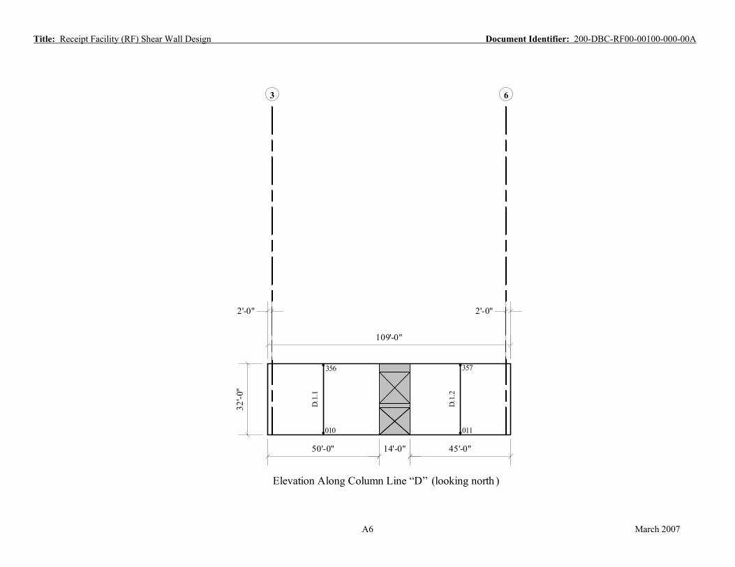
Elevation Along Column Line D A6
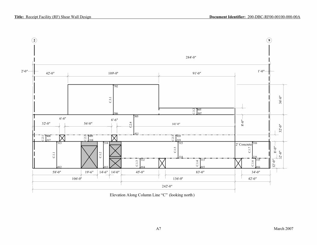
Elevation Along Column Line C A7
Elevation Along Column Line B A8
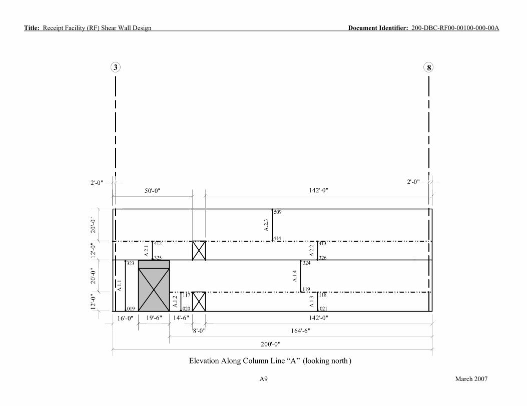
Elevation Along Column Line A A9
Elevation Along Column Line 9 A10
Elevation Along Column Line 8 A11
Elevation Along Column Line 7 A12
Elevation Along Column Line 6 A13
Elevation Along Column Line 5 A14
Elevation Along Column Line 4 A15
Elevation Along Column Line 3 A16
Elevation Along Column Line 2 A17
A2 March 2007
Title: Receipt Facility (RF) Shear Wall Design Document Identifier: 200-DBC-RF00-00100-000-00A
A3 March 2007
Y = 217
X =
21
X =
64
X =
110
X =
169
X =
208
X =
260
X =
303
Y = 258
Y = 301
Y = 340
Y = 184
Y = 102
X =
128
Y
X(0,0,0)
21'-0"
102'
-0"
At top of base -mat, Z = 0'-0" (+Z is out of paper)

3 8
2'-0" 2'-0" 50'-0" 142'-0"
501
3 .
0" 2
F.-32
'
403
" 1 401 2 402 0 . .-' 2 2
12 F. 303 F. 304 302 301
.4
1" .F0 .3
-'32 103
1F.
1 0"
-
101 2 102 . .' 1 1
12 F. F.
001 002 003
50'-0" 90'-0" 11'-0"
148'-0" 41'-0"
200'-0"
Elevation Along Column Line “F ” (looking north )
March 2007
Title: Receipt Facility (RF) Shear Wall Design Document Identifier: 200-DBC-RF00-00100-000-00A
A4

Title: Receipt Facility (RF) Shear Wall Design Document Identifier: 200-DBC-RF00-00100-000-00A
E.1.
6
2
2' Concrete
24'-0" 62'-0" 45'-0" 39'-0" 34'-0"
242'-0"
284'-0"
93'-0"
E.3.
1
E.1.
1
E.2.
2
E.2.
3
E.2.
1
E.2.
4
E.3.
3
E.1.
2
E.1.
3
E.1.
4
E.1.
7
E.1.
8 E.
1.9
8'-0
" 8'
-0"
8'-0
"
32'-0
" 36
'-0"
11'-0" 92'-0" 92'-0" 42'-0"
35'-0"
86'-6"
9
2'-0"
1'-0"
E.1.
5
32'-0
"
6'-0"
14'-0"
33'-0" 8'-0"
8'-0"
6'-0"
E.3.
2
16'-0"
109'-0"
42'-0"
17'-0" 97'-6"
91'-0"
004 104
005 105
106
006 007
107
008
305
108
306
109
307
009
110 111
308 309 310 311
103
404 406 407
405
502 503 504 601 602
603
701
Elevation Along Column Line “E” (looking north )
12'-0
"
12'-0
"
A5 March 2007
63
32'-0
"
D.1.
2
D.1.
1
109'-0"
2'-0" 2'-0"
010 011
356 357
50'-0" 14'-0" 45'-0"
Title: Receipt Facility (RF) Shear Wall Design Document Identifier: 200-DBC-RF00-00100-000-00A
Elevation Along Column Line “D” (looking north )
A6 March 2007
Title: Receipt Facility (RF) Shear Wall Design Document Identifier: 200-DBC-RF00-00100-000-00A
9
2' Concrete
C.2.
3
C.2.
1
C.2.
4
C.3.
1
C.1.
6 C.
1.7
14'-6"
32'-0" 56'-0"
C.2.
2
141'-0"
58'-0" 45'-0" 83'-0" 19'-6" 14'-0"
C.1.
1
C.1.
2
C.1.
3
C.1.
4
C.1.
5 136'-0"
34'-0"
42'-0"
2'-0" 1'-0"
32'-0
" 8'-0
" 32
'-0"
36'-0
"
2
6'-6" 6'-6"
242'-0"
284'-0"
106'-0"
42'-0" 109'-0" 91'-0"
C.3.
2
8'-0
"
012 013 014 015 016
313 314
112 113 114
115 116
315 316 317 318 319 408 409 410
411
505 506 507
605
702
12'-0
"
Elevation Along Column Line “C” (looking north )
A7 March 2007

3 4
14'-6" 19'-6" 16'-0"
32'-0
" 32
'-0"
2'-0" 2'-0"
50'-0"
B.2.
1 322
508
B.1.
1
017
320
B.1.
2
018
321
Title: Receipt Facility (RF) Shear Wall Design Document Identifier: 200-DBC-RF00-00100-000-00A
Elevation Along Column Line “B” (looking north )
A8 March 2007
83
12'-0
"
A.2
.3
A.2
.1
A.2
.2A
.1.3
A.1
.4
200'-0"
14'-6"
50'-0" 142'-0"
16'-0"
20'-0
" 12
'-0"
20'-0
"
142'-0"
164'-6"
A.1
.2
A.1.
1
2'-0" 2'-0"
19'-6"
8'-0"
019 020 021
117 118 119
323 324 325 326
412 413 414
509
Elevation Along Column Line “A” (looking north )
Title: Receipt Facility (RF) Shear Wall Design Document Identifier: 200-DBC-RF00-00100-000-00A
A9 March 2007

E C
32'-0
"
1'-0" 1'-0"
327
2' Concrete 9.
1.1
022
78'-0"
Title: Receipt Facility (RF) Shear Wall Design Document Identifier: 200-DBC-RF00-00100-000-00A
Elevation Along Column Line “9” (looking west)
A10 March 2007
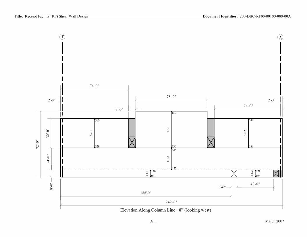
AF
'
8'-0
"
74 -0"
74'-0" 8'-0"
186'-0"
40'-0"
8.2.
1
8.2.
2
8.1.
1
8.1.
2
8.1.
3
242'-0"
24'-0
" 32
'-0"
2'-0" 2'-0"
6'-6"
78'-0"
72'-0
"
8.3.
1
023 024 120 121
122
328 329 330 331
510 511
607
Elevation Along Column Line “8” (looking west)
Title: Receipt Facility (RF) Shear Wall Design Document Identifier: 200-DBC-RF00-00100-000-00A
A11 March 2007
Title: Receipt Facility (RF) Shear Wall Design Document Identifier: 200-DBC-RF00-00100-000-00A
A
8'-0
"
16'-0"
94'-0" 22'-0"
7.2.
1
7.2.
5
7.1.
4
242'-0"
24'-0
" 24
'-0"
F
2'-0" 2'-0"
8'-0
"
48'-0" 48'-0"
16'-0"
22'-0"
54'-0"
74'-0" 54'-0"
74'-0"
74'-0" 74'-0"
7.1.
2
7.1.
1
7.1.
3
7.1.
5
7.1.
6
7.2.
4
7.2.
6
7.2.
2
7.2.
3
025 026 027 028 123 124
125 126 127
128
332 333 334 335 336 337 419 420 422
421 423
424
512 513
Elevation Along Column Line “7” (looking west)
A12 March 2007
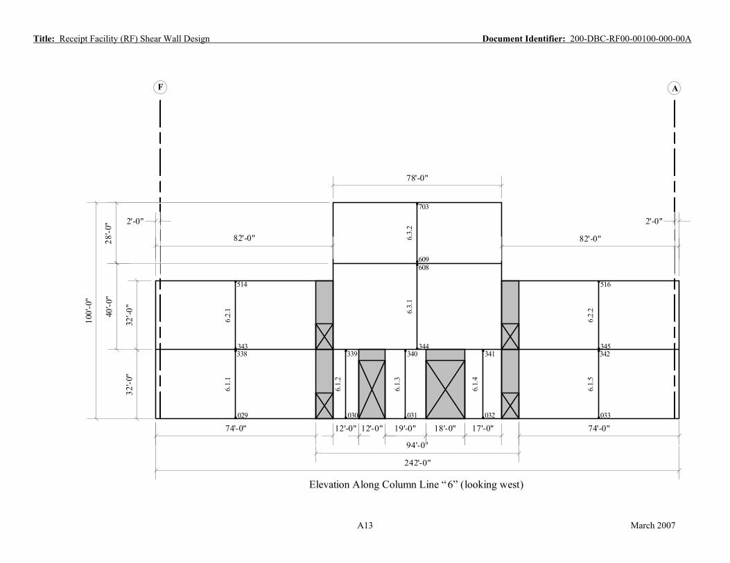
AF
78'-0"
100'
-0"
40'-0
" 28
'-0"
94'-0"
242'-0"
32'-0
" 32
'-0"
74'-0" 74'-0" 12'-0" 19'-0" 17'-0" 18'-0" 12'-0"
82'-0" 6.3.
2
609
703
2'-0"
82'-0"
6.3.
1
344
608
6.2.
1
343
514
6.2.
2
345
516
6.1.
1
029
338
6.1.
2
030
339
6.1.
3
031
340
6.1.
4
032
341
6.1.
5
033
342
2'-0"
Title: Receipt Facility (RF) Shear Wall Design Document Identifier: 200-DBC-RF00-00100-000-00A
Elevation Along Column Line “ 6” (looking west)
A13 March 2007

CE
5.1.
1
78'-0"
32'-0
"
2'-0" 2'-0"
034
346
Title: Receipt Facility (RF) Shear Wall Design Document Identifier: 200-DBC-RF00-00100-000-00A
Elevation Along Column Line “5” (looking west)
A14 March 2007

F
62'-0" 12'-0" 70'-0"
86'-0"
74'-0"
4.1.
1
4.1.
2
4.1.
3
4.1.
4
4.1.
5
4.2.
3
4.2.
4
4.2.
24.
2.1
20'-0
" 20
'-0"
A
2'-0" 2'-0"
32'-0
" 32
'-0"
035 036 037 038
129 130 131 132 133
347 348 349
425 427 428 426
519 520
12'-0"
86'-0"
12'-0"
44'-0" 20'-0" 66'-0" 62'-0" 12'-0" 8'-0"
22'-0" 8'-0"
242'-0"
Elevation Along Column Line “4” (looking west)
Title: Receipt Facility (RF) Shear Wall Design Document Identifier: 200-DBC-RF00-00100-000-00A
A15 March 2007
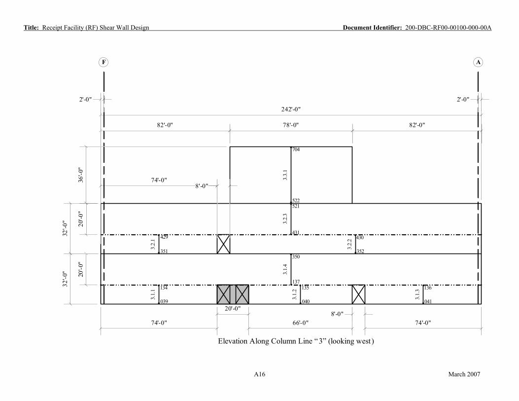
Title: Receipt Facility (RF) Shear Wall Design Document Identifier: 200-DBC-RF00-00100-000-00A
F A
20'-0"
3.1.
2
3.1.
4
20'-0
" 20
'-0"
82'-0" 78'-0"
242'-0"
3.1.
1
3.1.
3
74'-0" 8'-0"
3.2.
1
3.2.
3
3.2.
2
3.3.
1
36'-0
"
2'-0" 2'-0"
32'-0
" 32
'-0"
039 040 041
134 135 136 137
350 351 352
429 430 431
521 522
704
82'-0"
8'-0" 74'-0" 66'-0" 74'-0"
Elevation Along Column Line “3” (looking west)
A16 March 2007
E C
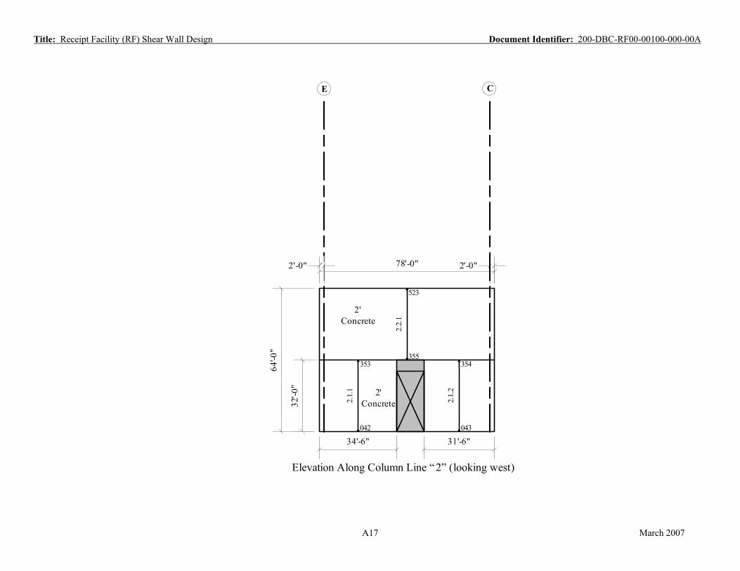
`2'-0" 78'-0" 2'-0"
32'-0
"
64'-0
"
2.2.
1
2' Concrete
355
523
2.1.
1
042
353
2' Concrete 2.
1.2
043
354
34'-6" 31'-6"
Title: Receipt Facility (RF) Shear Wall Design Document Identifier: 200-DBC-RF00-00100-000-00A
Elevation Along Column Line “2” (looking west)
A17 March 2007