Embed Size (px)
Citation preview

Safety Instructions & Operator's Manual for
REAR ENGINE RIDING MOWERSERIES 18
MODELS281318BE301318BE3314518BVE331518KVE
MODEL NUMBER EXPLANATION
CUTTING WIDTHENGINE HPSERIES DESIGNATION
I 33114sl18I B I v I E II I ENGINE OPTIONS
ENGINE TYPEENGINE MODEL
28 -28" Cutting Deck 13 - 13.0 HP Engine30 - 30" Cutting Deck 145 - 14.5 HP Engine33 -33" Cutting Deck 15 - 15.0 HP Engine
18 - Series Designation B - Briggs Engine V - Over HeadK - Kohler Engine Valve
E - Electric Start
Thank you for buying a SNAPPER Product! Before operating your machine, read this manual carefully and payparticular attention to the "IMPORTANT SAFETY INSTRUCTIONS" on Pages 2 & 3. Remember that all powerequipment can be dangerous if used improperly. Also keep in mind that SAFETY requires careful use inaccordance with the operating instructions and common sense!
SNAPPER, McDonough,GA., 30253 U.S.A.
COPYRIGHT © 1999SNAPPER INC.ALL RIGHTS RESERVED
MANUAL No. 4-7008 (REV. 1, 8/20/99)

IMPORTANT SAFETY INSTRUCTIONS
WARNING: This powerful cutting machine is capable of amputating hands and feet and can throw objects thatcan cause injury and damage! Failure to comply with the following SAFETY instructions could result in seriousinjury or death to the operator or other persons. The owner of the machine must understand these instructionsand must allow only persons who understand these instructions to operate machine. Each person operating themachine must be of sound mind and body and must not be under the influence of any substance, which mightimpair vision, dexterity or judgment. If you have any questions pertaining to your machine which your dealercannot answer to your satisfaction, call or write the Customer Service Department at SNAPPER, McDonough,Georgia 30253. Phone: (1-800-935-2967).
PROTECTION FOR CHILDRENTragic accidents can occur if the operator is not alertto the presence of children. Children are oftenattracted to the machine and the mowing activity.Never assume that children will remain where you lastsaw them.1. KEEP children out of the mowing area and under
the watchful care of a responsible adult.2. DO NOT allow children in yard when machine is
operated (even with the blade OFF).3. DO NOT allow children or others to ride on
machine or on attachments (even with the bladesOFF). They may fall and be seriously injured.
4. DO NOT allow pre-teenage children to operatemachine.
5. ALLOW only responsible adults & teenagers withmature judgment under close adult supervision tooperate machine.
6. DO NOT operate blades in reverse. STOP BLADES.LOOK and SEE behind and down for children, petsand hazards before and while backing.
7. USE EXTRA CARE when approaching blindcorners, shrubs, trees, or other objects that mayobscure vision.
PROTECTION AGAINST TIPOVERSSlopes are a major factor related to loss-of-controland tip-over accidents, which can result in severeinjury or death. All slopes require extra CAUTION. Ifyou cannot back up the slope or if you feel uneasy onthe slope, DO NOT mow it. Use extra care with grasscatchers or other attachments; these affect thehandling and the stability of the machine.1. DO NOT operate machine on slopes exceeding 15
degrees (27% grade).2. Exercise EXTREME CAUTION on slopes above 10
degrees (18% grade). Turn blades OFF whentraveling uphill. Use a slow speed and avoidsudden or sharp turns.
3. DO NOT operate machine back and forth acrossface of slopes. Operate up and down. Practice onslopes with blades off.
4. AVOID uphill starts. If machine stops going uphillor tires lose traction, turn blades OFF and backslowly down the slope.
PROTECTION AGAINST TIPOVERS(Continued From Previous Column)5. STAY ALERT for holes and other hidden hazards.
Tall grass can hide obstacles. Keep away fromditches, washouts, culverts, fences andprotruding objects.
6. KEEP A SAFE DISTANCE (at least 3 feet) awayfrom edge of ditches and other drop offs. Themachine could turn over if an edge caves in.
7. Always begin forward motion slowly and withcaution.
8. Use weights or a weighted load carrier in accordancewith instructions supplied with a grass catcher. DONOT operate machine on slopes exceeding 10degrees (18% grade) when equipped with grasscatcher.
9. DO NOT put your foot on the ground to try tostabilize the machine.
10. DO NOT operate machine on wet grass. Reducedtraction could cause sliding.
11. DO NOT operate machine under any conditionwhere traction, steering or stability is doubtful.
PREPARATION1. Read, understand, and follow instructions and
warnings in this manual and on the machine,engine and attachments. Know the controls andthe proper use of the machine before starting.
2. Only mature, responsible persons shall operatethe machine and only after proper instruction.
3. Data indicates that operators age 60 and above,are involved in a large percentage of mower-related injuries. These operators should evaluatetheir ability to operate the mower safely enough toprotect themselves and others from serious injury.
4. Handle fuel with extra care. Fuels are flammable
and vapors are explosive. Use only an approvedfuel container. DO NOT remove fuel cap or addfuel with engine running. Add fuel outdoors onlywith engine stopped and cool. Clean spilled fuelfrom machine. DO NOT smoke.
5. Practice operation of machine with BLADES OFFto learn controls and develop skills.
6. Check the area to be mowed and remove allobjects such as toys, wire, rocks, limbs and otherobjects that could cause injury if thrown by bladeor interfere with mowing.
IMPORTANT SAFETY INSTRUCTIONS
PREPARATION(Continued From Previous Page)7. Keep people and pets out of mowing area.
Immediately STOP blades, STOP engine, andSTOP machine if anyone enters the area.
8. Check shields, deflectors, switches, bladecontrols and other safety devices frequently forproper operation and location.
9. Make sure all safety decals are clearly legible.Replace if damaged.
10. Protect yourself when mowing and wear safetyglasses, long pants and substantial footwear.
11. Know how to STOP blades and engine quicklyin preparation for emergencies.
12. Use extra care when loading or unloading themachine into a trailer or truck.
13. Check grass catcher components frequently forsigns of wear or deterioration and replace asneeded to prevent injury from thrown objectsgoing through weak or worn spots.
OPERATION1. Mount and dismount machine from left side.2. Start engine from operator's seat, if possible.
Make sure blades are OFF and parking brake isset.
3. DO NOT leave machine with engine running.STOP engine, STOP blades, SET brake, andRemove key before leaving operators positionof any reason.
4. DO NOT operate machine unless properlyseated with feet on feet rests or pedal(s).
5. STOP BLADES and ENGINE and make sureblades have stopped before removing grasscatcher or unclogging mower to prevent loss offingers or hand.
6. Blades must be OFF except when cutting grass.Set blades in highest position when mowingover rough ground.
7. Keep hands and feet away from rotating bladesunderneath deck. DO NOT place foot on groundwhile BLADES are ON or machine is in motion.
8. DO NOT operate machine without entire grasscatcher or guards in place. DO NOT pointdischarge at people, passing cars, windows ordoors.
9. Slow down before turning.10. Watch out for traffic when near or crossing
roadways.11. STOP engine immediately after striking an
obstruction. Inspect machine and repairdamage before resuming operation.
12. Operate machine only in daylight or with goodartificial light.
13. Move joystick (if equipped) SLOWLY tomaintain control during speed and directionalchanges.
OPERATION(Continued From Previous Column)14. Exercise CAUTION when pulling loads. Limit
loads to those you can safely control and attachloads to hitch plate as specified with SNAPPERattachment instructions.
15. DO NOT operate engine in enclosed areas.Engine exhaust gases contain carbonmonoxide, a deadly poison.
MAINTENANCE1. DO NOT store machine or fuel container inside
where fumes may reach an open flame, spark orpilot light such as in a water heater, furnace,clothes dryer or other gas appliance. Allowengine to cool before storing machine in anenclosure. Store fuel container out of the reachof children in a well ventilated, unoccupiedbuilding.
2. Keep engine free of grass, leaves or excessgrease to reduce fire hazard and engineoverheating.
3. When draining fuel tank, drain fuel into anapproved container outdoors and away fromopen flame.
4. Check brakes frequently; adjust, repair orreplace as needed.
5. Keep all bolts, nuts and screws properly tight.Check that all cotter pins are in proper position.
6. Always provide adequate ventilation whenrunning engine. Exhaust gases contain carbonmonoxide, an odorless and deadly poison.
7. Disconnect negative (black) cable from batterybefore performing maintenance or service.Cranking engine could cause injury.
8. DO NOT work under machine without safetyblocks.
9. Service engine and make adjustments onlywhen engine is stopped. Remove spark plugwire(s) from spark plug(s) and secure wire(s)away from spark plug(s).
10. DO NOT change engine governor speedsettings or overspeed engine.
11. Lubricate machine at intervals specified inmanual to prevent controls from binding.
12. Mower blades are sharp and can cut. Wrap theblades or wear heavy leather gloves and useCAUTION when handling them.
13. DO NOT test for spark by grounding spark plugnext to spark plug hole; spark plug could ignitegas exiting engine.
14. Have machine serviced by an authorizedSNAPPER dealer at least once a year and havethe dealer install any new safety devices.
15. Use only genuine SNAPPER replacement partsto assure that original standards aremaintained.

TABLE OF CONTENTS
IMPORTANT SAFETY INSTRUCTIONS .......................................................... 2-3TABLE OF CONTENTS ...................................................................................... 4SECTION 1 - FAMILIARIZATION ....................................................................... 5SECTION 2 - OPERATING INSTRUCTIONS ................................................. 6-11
Pre-start Checklist ......................................................................................................... 6
Operator's Seat Adjustment .......................................................................................... 6Starting & Stopping Engine, Blade & Wheel Drive ................................................ 7-10Starting & Stopping Mower Blades ......................................................................... 9-10Starting & Stopping Wheel Drive ............................................................................. 9-10Parking Brake ............................................................................................................... 11Cutting Height Adjustment .......................................................................................... 11
SECTION 3 - MAINTENANCE INSTRUCTIONS ......................................... 12-16Service -After First 5 Hours ....................................................................................... 12
Change Engine Oil .................................................................................................... 12Service Engine Air Cleaner ...................................................................................... 12Check Mower Blade ............................................................................................. 12-13Check Blade Drive Belt ............................................................................................. 13Blade Brake ............................................................................................................... 13Service Brake / Park Brake ....................................................................................... 13Check Interlock System ............................................................................................ 13Lubrication - Grease Fittings .................................................................................. 14
Service - Every 25 Operating Hours .......................................................................... 14Battery Fluid Level .................................................................................................... 14Mower Deck Levelness ............................................................................................. 14Clean Mower Deck .................................................................................................... 14Mower Blade Spindle - Lubrication ......................................................................... 14Mower Deck Linkage- Lubrication ......................................................................... 14Front Wheel Bearing - Lubrication .......................................................................... 14Rear Axle Bearing - Lubrication .............................................................................. 15Differential / Chain Case- Lubrication ................................................................... 15
Service - Annually ........................................................................................................ 16Engine ........................................................................................................................ 16Fuel Filter ................................................................................................................... 16
Every Two Years ........................................................................................................... 16Storage - Out of Season .............................................................................................. 16Removing Fuel Tank .................................................................................................... 16
SECTION 4- ADJUSTMENTS AND REPAIR ............................................... 17-25Engine Adjustments & Repair ..................................................................................... 17Mower Deck & Component Adjustments ................................................................... 17Blade Brake Adjustment .............................................................................................. 17Mower Deck Adjustment (Side to Side Levelness) ................................................... 18Mower Deck Adjustment (Front to Rear Levelness) ................................................. 18Cutting Height Adjustment .......................................................................................... 19Rear Engine Rider Drive Components ....................................................................... 19Wheel Brake Adjustment ........................................................................................ 19-20Mower Blade Replacement .......................................................................................... 21Blade Sharpening ......................................................................................................... 21Mower Drive Belt Removal/Replacement .................................................................. 22Battery Removal, Replacement, Service ............................................................... 23-25
ACCESSORIES ................................................................................................ 25
TROUBLESHOOTING ................................................................................. 26-27MAINTENANCE SCHEDULE ............................................................................ 28MAINTENANCE/REPLACEMENT PARTS ........................................................ 29WARRANTY ..................................................................................................... 30PRIMARY MAINTENANCE .......................................................................... 31-34

Section 1 - FAMILIARIZATION
REARBUMPER
FUELTANK
FUELFILLERCAP
VENT/
/STEERINGWHEEL
/I
OPERATOR'S SEAT
SHIFT LEVER
PANEL
(See Insert)
CLUTCH/BRAKEPEDAL
DECK LIFTLEVER
DISCHARGEDEFLECTOR
MOWER DECK
CONTROL PANEL
IGNITIONSWITCH
ENGINESPEEDCONTROL
PARKBRAKELEVER
BLADE
LEVER
MOWERBELTCOVER
BLADEPEDALS
1.1 INTRODUCTIONThis manual has been prepared for the operator's of theSNAPPER Rear Engine Rider. Its purpose, aside fromrecommending standard operating procedures androutine service requirements, is to promote SAFETYthrough the use of accepted operating practices. Read,Understand and Follow the IMPORTANT SAFETYINSTRUCTIONS on Pages 2 & 3 of this manual and AllSAFETY messages on the Rear Engine Rider and itsattachments before operating.
FIGURE 1.1
1.2 NOMENCLATUREThe nomenclature drawing above, Figure 1.1, shows theessential parts of the SNAPPER Rear Engine Rider. It isrecommended that all operator's of this equipmentbecome thoroughly familiar with the controls,components, and operation of this machine beforeoperating. Specific details involving the engine are foundin the separate engine owner's manual. Study thesemanuals before operating and keep both handy for futurereference.

Section 2 - OPERATING INSTRUCTIONS
2.1 PRE-START CHECK LIST 2.2Make the following checks and perform the servicerequired before each start-up.2.1.1. Check tires and add or release air as neededto bring pressure to 12 psi in front and 12 psi in reartires.2.1.2. Check guards, deflectors and covers to makesure all are in place and securely tightened.2.1.3. Check engine oil and add oil as needed tobring level up to the FULL mark. Refer to engineowner's manual for oil specifications. See Figure 2.1.
FIGURE 2.1
2.1.4. Adjust seat as needed to most comfortableposition. Refer to Section "OPERATOR'S SEATADJUSTMENT".2.1.5. Check blade control to insure it works freely.If blade pedals are depressed, blade lever can bemoved manually from "ON" to "OFF" to stopblade.2.1.6. Clean exterior surfaces of cutting deck andengine of any accumulation of dirt, grass, oil, etc.Keep engine air intake screen and cooling fins clear atall times.2.1.7. Add fuel to tank after pushing the Rear EngineRider outside where fumes can dissipate. Make surefuel filler cap is tight and vent is open after refueling.Refer to engine owner's manual for fuel specifications.See Figure 2.2.
OPERATOR'S SEAT ADJUSTMENT2.2.1. FRONT TO REAR ADJUSTMENT1. With the engine stopped, loosen the two adjustingknobs and move seat to desired position. Afteradjustment, tighten knobs securely. If seat does notmove after loosening knobs, it may be necessary toloosen the 5/16" patch lock screws located at the rearof the seat using a 1/2 inch wrench. See Figure 2.3.
ADJUSTING OPERATOR'SKNOBS SEATP.N. 2-3191
5116"LOCK SCREWS
(DO NOTOVERTIGHTEN)
II
6/16" PATCHLOCK SCREWS
(DO NOTOVERTIGHTEN)
FRONTOF SEAT
KNOBS P.N.2-8669
OPEN
CAP "_''_"_b_
FIGURE 2.2
FIGURE 2.3
Section 2 - OPERATING INSTRUCTIONS
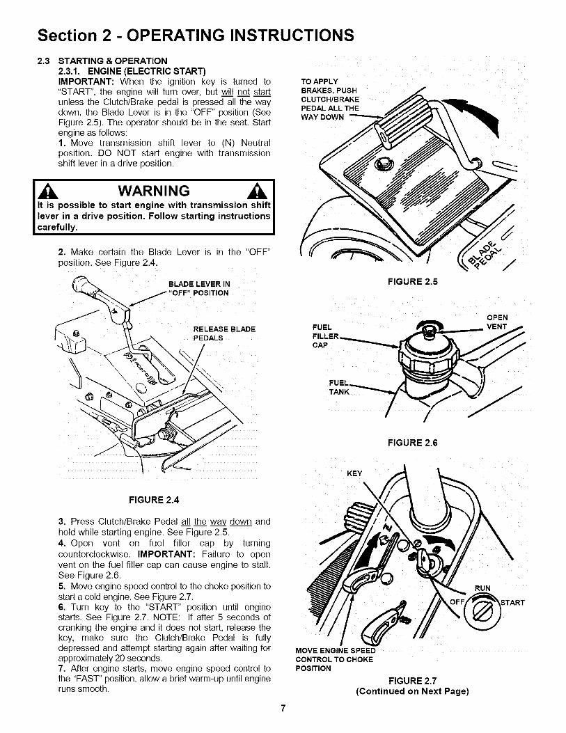
2.3 STARTING & OPERATION2.3.1. ENGINE (ELECTRIC START)IMPORTANT: When the ignition key is turned to"START", the engine will turn over, but will not startunless the Clutch/Brake pedal is pressed all the waydown, the Blade Lever is in the "OFF" position (SeeFigure 2.5). The operator should be in the seat. Startengine as follows:1. Move transmission shift lever to (N) Neutralposition. DO NOT start engine with transmissionshift lever in a drive position.
WARNING A.IIt is possible to start engine with transmission shift Ilever in a drive position. Follow starting instructions [carefully. I
2. Make certain the Blade Lever is in the "OFF"position. See Figure 2.4.
( BLADE LEVER IN
.jj,OFF" POS,T,ON
RELEASE BLADE
FIGURE 2.4
3. Press Clutch/Brake Pedal all the wa_ down andhold while starting engine. See Figure 2.5.4. Open vent on fuel filler cap by turningcounterclockwise. IMPORTANT: Failure to openvent on the fuel filler cap can cause engine to stall.See Figure 2.6.5. Move engine speed control to the choke position tostart a cold engine. See Figure 2.7.6. Turn key to the "START" position until enginestarts. See Figure 2.7. NOTE: If after 5 seconds ofcranking the engine and it does not start, release thekey, make sure the Clutch/Brake Pedal is fullydepressed and attempt starting again after waiting forapproximately 20 seconds.7. After engine starts, move engine speed control tothe "FAST" position, allow a brief warm-up until engineruns smooth.
TO APPLY
BRAKES, PUSHCLUTCH/BRAKEPEDAL ALL THEWAY DOWN
FIGURE 2.5
OPEN
FUEL _ VENT
FIGURE 2.6
KEY
MOVE ENGINE SPEEDCONTROL TO CHOKEPOSITION
FIGURE 2.7(Continued on Next Page)
RUN

Section 2 - OPERATING INSTRUCTIONS
2.3 STARTING & OPERATION2.3.1. ENGINE (ELECTRIC START) (Continued)8. Should the battery be too weak to start the engine,Refer to Section "ENGINE (MANUAL START)" tomanually start the electric start engines.9. On Model 331418BVE, the engine is equipped witha fuel shut-off solenoid. If the battery is dead, theengine can be started with the recoil back-up starter ifthe throttle control is in the choke position (HOT engineor COLD engine).
2.3.2. ENGINE (MANUAL START)IMPORTANT: When the ignition key is turned to"RUN", and the recoil handle is pulled, the enginewill turn over, but will not start unless theClutch/Brake Pedal is pressed all the way down withParking Brake engaged (See Figure 2.8) and theBlade Lever is in the "Off" position (See Figure 2.4).Start engine as follows:1. Move transmission shift lever to (N) Neutralposition. DO NOT start engine with transmission shiftlever in a drive position.
WARNINGIt is possible to start engine with transmission shift Ilever in a drive position. Follow starting instructionscarefully. I
2. Make certain the Blade Lever is in the "OFF"position. See Figure 2.4.3. Press Clutch/Brake Pedal all the wa_zdown, liftParking Brake Lever and release the Clutch/BrakePedal to set Parking Brake. See Figure 2.8.
PUSH CLUTCH/BRAKEPEDAL ALL THE WAY\
\DOWN
5. Move engine speed control to the choke positionto start a cold engine. See Figure 2.7.6. Turn key to "RUN" position. See Figure 2.9.
KEY
RUN
FIGURE 2.9
7. Pull starter rope with a smooth, even motion untilengine starts. Always guide the starter rope backinto the recoil housing. Never allow rope to snapback. After Engine starts, move engine speedcontrol to the "FAST" position.8. Allow a brief warm-up until engine runs smooth.
/ MOVE PARKBRAKE LEVERTO "ON"
FIGURE 2.8
4. Open vent on fuel filler cap by turningcounterclockwise. NOTE: Failure to open vent onthe fuel filler cap can cause engine to stall.

Section 2 - OPERATING INSTRUCTIONS
WARNINGOnce blade is disengaged, it should come to acomplete stop in 3 seconds or less. If the bladecontinues to rotate after 3 seconds, the blade brakemust be adjusted. Refer to Section "BLADE BRAKEADJUSTMENT" for adjustment procedures or returnmachine to an authorized SNAPPER dealer foradjustment. DO NOT CONTINUE to operate machineuntil blade brake is adjusted and functioningproperly.
2.3 STARTING & OPERATION2.3.3. MOWER BLADE1. With engine running, move engine speed controlto the "FAST" position.2. Move blade lever forward to the "ON" position,then depress blade pedals to hold blade lever in the"ON" position. See Figure 2.10.
IMPORTANT: You cannot engage the blade lever if theblade pedal is depressed first.
BLADE LEVER SHOWN IN"ON" POSITION
BLADE PEDALSHOWNDEPRESSED
FIGURE 2.10
IL WARNINGDO NOT operate blades in reverse. STOP BLADES.ILOOK and SEE behind and down for children, petsand hazards before and while backing.
FIGURE 2.11
/
!
2.3.4. WHEEL DRIVE1. With engine running, adjust engine speed controlto "FAST" position.2. Depress clutch/brake pedal. See Figure 2.11.3. Place transmission shift lever in notch for firstspeed. See Figure 2.12.4. Release clutch/brake pedal to begin desiredground speed.5. During forward motion, the transmission shiftlever may be placed in any desired forward speedwithout depressing the clutch/brake pedal.
NOTE: For best cutting results, move the transmissionshift lever into a slow forward speed and the enginespeed control to a fast position. This combination willallow the mower blades to lift the grass while cuttingsmoothly and evenly.
THERE AREFIVEDIFFERENTFORWARDGROUNDSPEEDS AND ONEREVERSE GROUNDSPEED
LEVERSHOWNINNEUTRAL POSITION
FIGURE 2.12

Section 2 - OPERATING INSTRUCTIONS
WARNINGDO NOT leave the machine with the engine running.STOP Blade. STOP engine. Shift to neutral andengage park brake. Remove key.
2.4 STOPPING - ENGINE, WHEEL DRIVE, BLADE2.4.1. ENGINE1. Stop engine by turning key to the "OFF" position.See Figure 2.13.
RUN
TO APPLYBRAKES, PUSHCLUTCH/BRAKEPEDAL ALL THEWAY DOWN
OFF
KEY
FIGURE 2.14
FIGURE 2.13
2.4.2. WHEEL DRIVE1. Stop motion of Rear Engine Rider by pushingclutch/brake pedal all the way "DOWN" to applybrake. See Figure 2.14.
WARNINGOnce blade is disengaged, it should come to acomplete stop in 3 seconds or less. If the bladecontinues to rotate after 3 seconds, the blade brakemust be adjusted. Refer to Section "BLADE BRAKEADJUSTMENT" for adjustment procedures or returnmachine to an authorized SNAPPER dealer foradjustment. DO NOT CONTINUE to operate machineuntil blade brake is adjusted and functioningproperly.
BLADE LEVER IN "OFF"POSITION
RELEASE BLADEPEDALS
FIGURE 2.15
2.4.3. MOWER BLADE
1. Stop mower blade by releasing blade pedals ormoving blade lever rearward to the "OFF" position.See Figure 2.15.
10

Section 2 - OPERATING INSTRUCTIONS
2.4 STOPPING - ENGINE, WHEEL DRIVE, BLADE2.4.4. PARK BRAKE
1. Engage park brake by pushing clutch/brake pedal"DOWN" and moving the park brake lever to the "ON"position. While holding the park brake lever "ON",release clutch/brake pedal to set park brake.See Figure 2.16.
PUSH CLUTCH/BRAKEPEDAL ALL THE WAY
MOVE PARK
//t] BRAKE LEVER
/// TO "ON"
FIGURE 2.16
2.5. CUTTING HEIGHT ADJUSTMENT1. Adjust cutting height as desired to any one of sixpositions using deck lift lever. When in desiredheight of cut, release latch, then try to move decklift lever to ensure lift lever latch is fully engaged.See Figure 2.18.
DECK LIFTLEVER
LIFT LEVERLATCH
FIGURE 2.18
2. Release park brake by pushing down on theclutch/brake pedal to release park brake lever. SeeFigure 2.17.
PUSH CLUTCH/BRAKEPEDAL ALL THE WAYDOWN
WARNINGDO NOT park machine on slopes.
FIGURE 2.17
11

Section 3 - MAINTENANCE
WARNINGDO NOT attempt any adjustments, maintenance,service or repairs with the engine running. STOPengine. STOP blade. Engage parking brake. Removekey. Remove spark plug wire from spark plug andsecure away from plug. Engine and components areHOT. Avoid serious burns, allow all parts to coolbefore working on machine. Fuel Filler Cap and ventmust be closed securely to prevent fuel spillage.
3.1
3.2
INTRODUCTIONTo retain the quality of the Rear Engine Rider, usegenuine SNAPPER replacement parts only. Contact alocal SNAPPER dealer for parts and serviceassistance. For the correct part or information for aparticular Rear Engine Riding Mower, always mentionthe model and serial number. SNAPPER recommendsreturning the Rear Engine Rider to an authorizedSNAPPER dealer annually for inspection and additionof any new devices which might upgrade the safety ofthe Rear Engine Rider. For the nearest SNAPPERdealer in your area, check the yellow pages under theheading LAWN MOWERS. For engine parts andservice, look for the engine manufacturer's dealersunder the heading, ENGINES - gasoline.
SERVICE - AFTER FIRST 5 HOURSRoutine maintenance is important to the performanceand life of your Rear Engine Rider. Service performedproperly and at the recommended interval is essential.Refer to Section "MAINTENANCE SCHEDULE" in thismanual and in the Engine Owner's Manual. Carefullycomplete all of the recommended service procedures.3.2.1. CHANGE ENGINE OIL1. Place bricks or wooden blocks under the frontwheels to lower rear of engine.2. Loosen or remove oil fill cap on engine.3. Loosen oil drain plug.4. Place a 2 quart minimum capacity containerunder the end of the oil drain. Open oil drain. SeeFigure 3.1 for oil drains used on the Rear EngineRiders.
. , PUL . OUT TO
PUSH IN AND ROTATECLOCKWISE TO CLOSE
REMOVE OIL PLUG TO /
ALLOWO,LTOROTATE COUNTER-
/ CLOCKWISEANDOPEN
FIGURE 3.1
5. After all the oil has drained, close the drain andwipe up any oil that may have spilled. See Figure 3.1.Dispose of used oil properly.6. Fill engine crankcase with new oil. Refer to yourengine owner's manual for oil specifications.7. Change oil filter on 14HP Kohler engines at everyoil change. Refer to your engine owner's manual forservice instructions.
3.2.2. SERVICE ENGINE AIR CLEANERThe engine is equipped with a dual element aircleaner. Both the foam pre-cleaner and cartridgerequire service. Refer to Engine Owner's Manual forrecommended service procedures.
3.2.3. CHECK MOWER BLADE1. Follow WARNING statement found on this page.2. Check fuel level in tank. If over 3/4 full, removetank. Refer to Section "REMOVING FUEL TANK".If 3/4 or less, proceed to next step.3. Carefully stand Rear Engine Rider on rear bumper.
Remove the battery if the Rear Engine Rider will beleft standing on the rear bumper for longer than 2hours. Refer to Section "BATTERY REMOVAL". DO
NOT use a cutting blade that shows signs ofexcessive wear or damage on the Rear Engine Rider.Refer to Section "MOWER BLADE REPLACEMENT"for proper blade inspection and service procedures.
4. Check torque of blade mounting bolts. Asnecessary, torque to 30 to 40 ft. Ibs. See Figure 3.2.5. Check blade for sharpness, wear and damage.Refer to Section "BLADE WEAR LIMITS".
I
30 TO 40 FT, LBS,
FIGURE 3.2
6. Check blade for straightness. Refer to Section"ADJUSTING MOWER BLADE".
12
Section 3 - MAINTENANCE
WARNINGDO NOT attempt any adjustments, maintenance,service or repairs with the engine running. STOPengine. STOP blade. Engage parking brake. Removekey. Remove spark plug wire from spark plug andsecure away from plug. Engine and components areHOT. Avoid serious burns, allow all parts to coolbefore working on machine. Fuel Filler Cap and ventmust be closed securely to prevent fuel spillage.
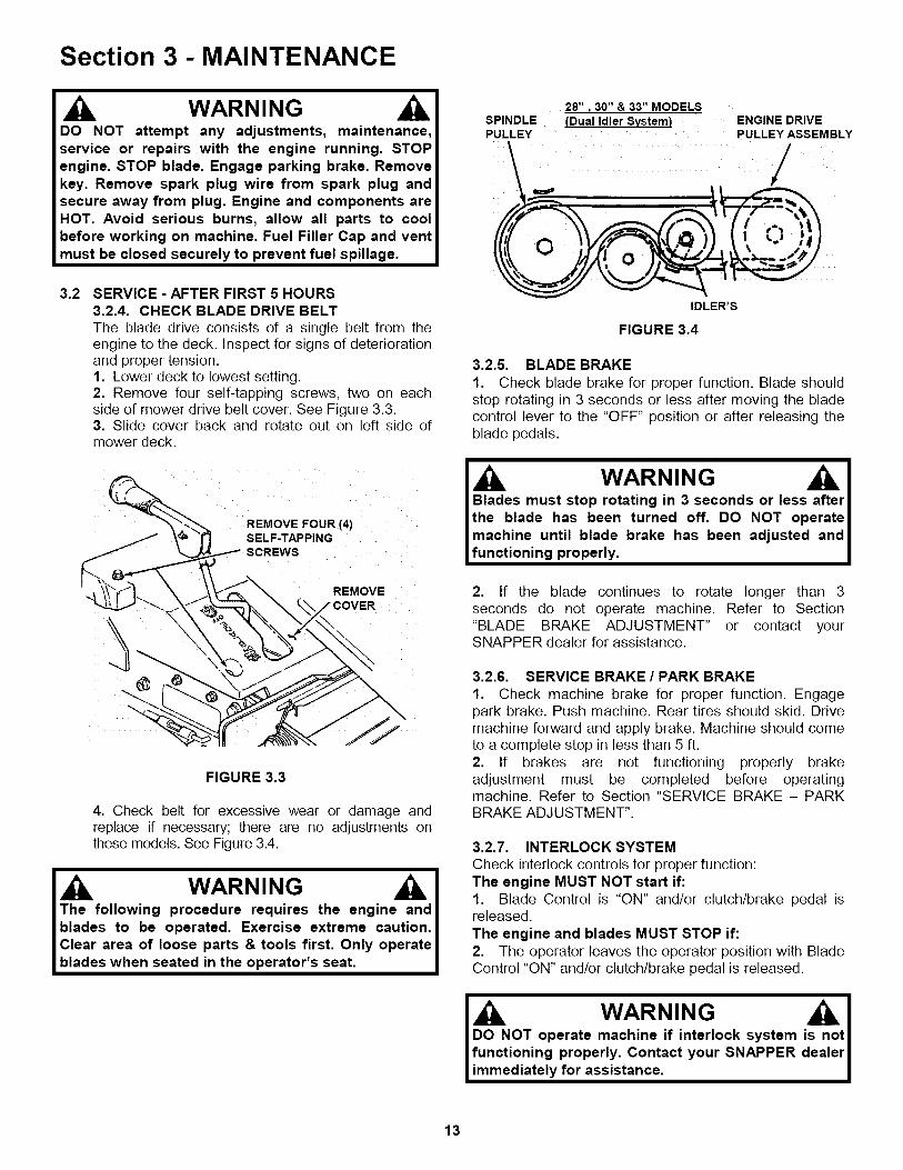
3.2 SERVICE - AFTER FIRST 5 HOURS3.2.4. CHECK BLADE DRIVE BELTThe blade drive consists of a single belt from theengine to the deck. Inspect for signs of deteriorationand proper tension.1. Lower deck to lowest setting.2. Remove four self-tapping screws, two on eachside of mower drive belt cover. See Figure 3.3.3. Slide cover back and rotate out on left side ofmower deck.
REMOVE FOUR (4)SELF-TAPPING
REMOVE
FIGURE 3.3
4. Check belt for excessive wear or damage andreplace if necessary; there are no adjustments onthese models. See Figure 3.4.
WARNINGThe following procedure requires the engine andblades to be operated. Exercise extreme caution.Clear area of loose parts & tools first. Only operateblades when seated in the operator's seat.
28" _30" & 33" MODELSSPINDLE (Dual Idler System) ENGINE DRIVEPULLEY ...... PULLEY ASSEMBLY
IDLER'S
FIGURE 3.4
3.2.5. BLADE BRAKE
1. Check blade brake for proper function. Blade shouldstop rotating in 3 seconds or less after moving the bladecontrol lever to the "OFF" position or after releasing theblade pedals.
I Blades must stop rotating in 3 seconds or less after Ithe blade has been turned off. DO NOT operate Imachine until blade brake has been adjusted and Ifunctioning properly. I
2. If the blade continues to rotate longer than 3seconds do not operate machine. Refer to Section"BLADE BRAKE ADJUSTMENT" or contact yourSNAPPER dealer for assistance.
3.2.6. SERVICE BRAKE / PARK BRAKE
1. Check machine brake for proper function. Engagepark brake. Push machine. Rear tires should skid. Drivemachine forward and apply brake. Machine should cometo a complete stop in less than 5 ft.2. If brakes are not functioning properly brakeadjustment must be completed before operatingmachine. Refer to Section "SERVICE BRAKE - PARKBRAKE ADJUSTMENT".
3.2.7. INTERLOCK SYSTEMCheck interlock controls for proper function:The engine MUST NOT start if:1. Blade Control is "ON" and/or clutch/brake pedal isreleased.
The engine and blades MUST STOP if:2. The operator leaves the operator position with BladeControl "ON" and/or clutch/brake pedal is released.
WARNING IDO NOT operate machine if interlock system tfunctioning properly. Contact your SNAPPER r
immediately for assistance,
13
Section 3- MAINTENANCE
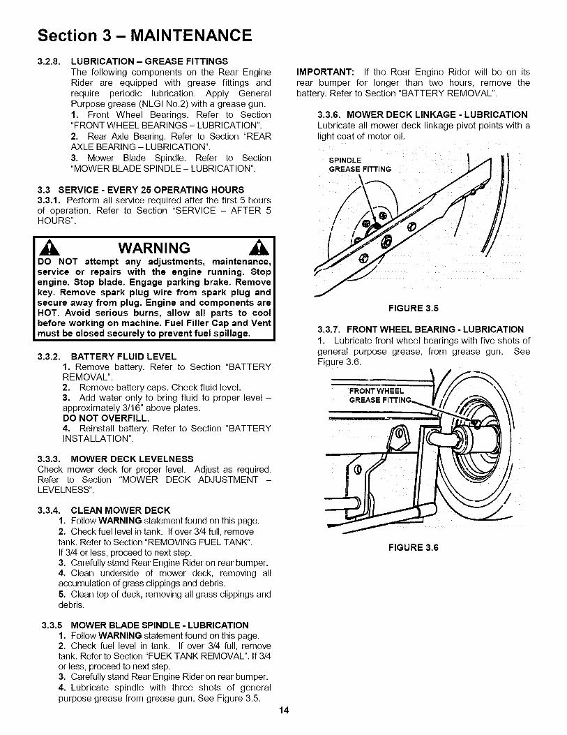
3.2.8. LUBRICATION - GREASE FITTINGSThe following components on the Rear EngineRider are equipped with grease fittings andrequire periodic lubrication. Apply GeneralPurpose grease (NLGI No.2) with a grease gun.1. Front Wheel Bearings. Refer to Section"FRONT WHEEL BEARINGS - LUBRICATION".2. Rear Axle Bearing. Refer to Section "REARAXLE BEARING - LUBRICATION".
IMPORTANT: If the Rear Engine Rider will be on itsrear bumper for longer than two hours, remove thebattery. Refer to Section "BATTERY REMOVAL".
3.3.6. MOWER DECK LINKAGE - LUBRICATIONLubricate all mower deck linkage pivot points with alight coat of motor oil.
3. Mower Blade Spindle. Refer to Section SPINDLE II, _ |_
..jf/j3.3 SERVICE - EVERY 25 OPERATING. HOURS .-3.3.1. Perform all service required after the first 5 hoursof operation. Refer to Section SERVICE - AFTER 5HOURS".
WARNINGDO NOT attempt any adjustments, maintenance,service or repairswith the engine running. Stopengine.Stop blade.Engage parking brake.Removekey. Remove spark plug wire from spark plug andsecure away from plug.Engine and components areHOT. Avoid serious burns, allow all parts to cool FIGURE 3.5before working on machine. Fuel Filler Cap and Ventmust be closed securely to prevent fuel spillage.
3.3.2. BATTERY FLUID LEVEL1. Remove battery. Refer to Section "BATTERYREMOVAL".2. Remove battery caps. Check fluid level.3. Add water only to bring fluid to proper level -approximately 3/16" above plates.DO NOT OVERFILL.4. Reinstall battery. Refer to Section "BATTERYINSTALLATION".
3.3.3. MOWER DECK LEVELNESSCheck mower deck for proper level. Adjust as required.Refer to Section "MOWER DECK ADJUSTMENT -LEVELNESS".
3.3.4. CLEAN MOWER DECK1. Follow WARNING statement found on this page.2. Check fuel level in tank. If over 3/4 full, removetank. Refer to Section "REMOVING FUEL TANK".If 3/4 or less, proceed to next step.3. Carefully stand Rear Engine Rider on rear bumper.4. Clean underside of mower deck, removing allaccumulation of grass clippings and debris.5. Clean top of deck, removing all grass clippings anddebris.
3.3.7. FRONT WHEEL BEARING - LUBRICATION
1. Lubricate front wheel bearings with five shots ofgeneral purpose grease, from grease gun. SeeFigure 3.6.
FRONT WHEELGREASE
FIGURE 3.6
3.3.5 MOWER BLADE SPINDLE- LUBRICATION1. Follow WARNING statement found on this page.2. Check fuel level in tank. If over 3/4 full, removetank. Refer to Section "FUEK TANK REMOVAL". If 3/4or less, proceed to next step.3. Carefully stand Rear Engine Rider on rear bumper.4. Lubricate spindle with three shots of generalpurpose grease from grease gun. See Figure 3.5.
14
Section 3 - MAINTENANCE
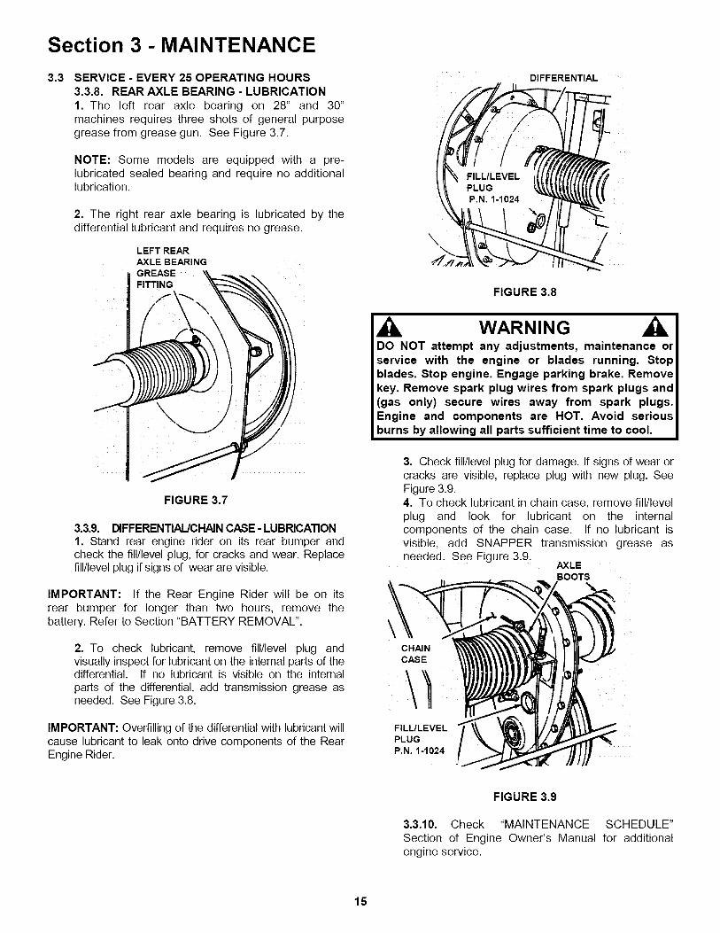
3.3 SERVICE - EVERY 25 OPERATING HOURS3.3.8. REAR AXLE BEARING - LUBRICATION1. The left rear axle bearing on 28" and 30"machines requires three shots of general purposegrease from grease gun. See Figure 3.7.
NOTE: Some models are equipped with a pre-lubricated sealed bearing and require no additionallubrication.
2. The right rear axle bearing is lubricated by thedifferential lubricant and requires no grease.
LEFT REARAXLE BEARINGGREASEFITTING
FIGURE 3.7
3.3.9. DIFFERENTIAL/CHAINCASE- LUBRICATION1. Stand rear engine rider on its rear bumper andcheck the fill/level plug, for cracks and wear. Replacefill/level plug if signs of wear are visible.
IMPORTANT: If the Rear Engine Rider will be on itsrear bumper for longer than two hours, remove thebattery. Refer to Section "BATTERY REMOVAL".
2. To check lubricant, remove fill/level plug andvisually inspect for lubricant on the internal parts of thedifferential. If no lubricant is visible on the internalparts of the differential, add transmission grease asneeded. See Figure 3.8.
IMPORTANT: Overfilling of the differential with lubricant willcause lubricant to leak onto drive components of the RearEngine Rider.
DIFFERENTIAL
\
FIGURE 3.8
WARNINGDO NOT attempt any adjustments, maintenance orservice with the engine or blades running. Stopblades. Stop engine. Engage parking brake. Removekey. Remove spark plug wires from spark plugs and(gas only) secure wires away from spark plugs.Engine and components are HOT. Avoid seriousburns by allowing all parts sufficient time to cool.
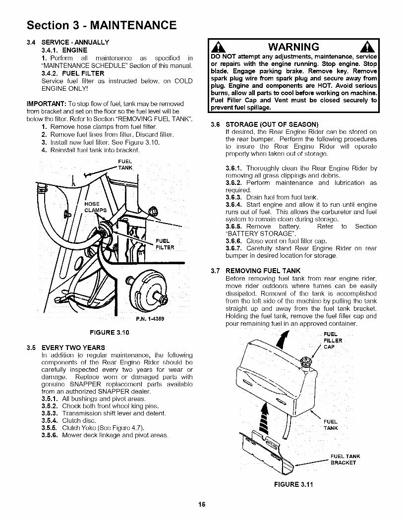
3. Check fill/level plug for damage. If signs of wear orcracks are visible, replace plug with new plug. SeeFigure 3.9.4. To check lubricant in chain case, remove fill/levelplug and look for lubricant on the internalcomponents of the chain case. If no lubricant isvisible, add SNAPPER transmission grease asneeded. See Figure 3.9.
AXLEBOOTS
\CHAINCASE
FILL/LEVELPLUGP.N. 1-1024
FIGURE 3.9
3.3.10. Check "MAINTENANCE SCHEDULE"Section of Engine Owner's Manual for additionalengine service.
15
Section 3 - MAINTENANCE
3.4 SERVICE - ANNUALLY3.4.1. ENGINE1. Perform all maintenance as specified in"MAINTENANCE SCHEDULE" Section of this manual.3.4.2. FUEL FILTERService fuel filter as instructed below, on COLDENGINE ONLY!
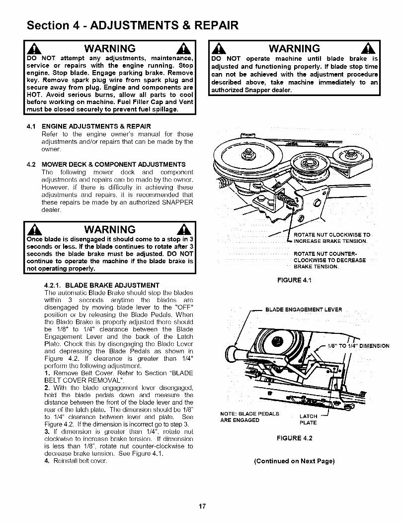
IMPORTANT: To stop flow of fuel, tank may be removedfrom bracket and set on the floor so the fuel level will bebelow the filter. Refer to Section "REMOVING FUEL TANK".
1. Remove hose clamps from fuel filter.2. Remove fuel lines from filter. Discard filter.
3. Install new fuel filter. See Figure 3.10.4. Reinstall fuel tank into bracket.
FUEL
FUELFILTER
3.5
1 ¸
P.N. 1-4359
FIGURE 3.10
EVERY TWO YEARSIn addition to regular maintenance, the followingcomponents of the Rear Engine Rider should becarefully inspected every two years for wear ordamage. Replace worn or damaged parts withgenuine SNAPPER replacement parts availablefrom an authorized SNAPPER dealer.3.5.1. All bushings and pivot areas.3.5.2. Check both front wheel king pins.3.5.3. Transmission shift lever and detent.3.5.4. Clutch disc.3.5.5. Clutch Yoke (See Figure 4.7).3.5.6. Mower deck linkage and pivot areas.
DO NOT attempt any adjustments, maintenance, serviceor repairs with the engine running. Stop engine. Stopblade. Engage parking brake. Remove key. Removespark plug wire from spark plug and secure away fromplug. Engine and components are HOT. Avoid seriousbums, allow all parts to cool before working on machine.Fuel Filler Cap and Vent must be closed securely toprevent fuel spillage.
3.6 STORAGE (OUT OF SEASON)If desired, the Rear Engine Rider can be stored onthe rear bumper. Perform the following proceduresto insure the Rear Engine Rider will operateproperly when taken out of storage.
3.6.1. Thoroughly clean the Rear Engine Rider byremoving all grass clippings and debris.3.6.2. Perform maintenance and ubrication asrequired3.6.3. Drain fuel from fuel tank.3.6.4. Start eng ne and allow it to run until engineruns out of fuel. This allows the carburetor and fuelsystem to remain clean during storage3.6.5. Remove battery. Refer to Section"BATTERY STORAGE".3.6.6. Close vent on fuel filler cap.3.6.7. Carefully stand Rear Engine Rider on rearbumper n desired location for storage.
3.7 REMOVING FUEL TANKBefore removing fuel tank from rear engine rider,move rider outdoors where fumes can be easilydissipated. Removal of the tank is accomplishedfrom the eft side of the machine by pulling the tankstraight up and away from the fuel tank bracket.Holding the fuel tank. remove the fuel filler cap andpour remaining fuel in an approved container.
__ UEL
FILLERCAP
tFUELTANK
FIGURE 3.11
16
Section 4 - ADJUSTMENTS & REPAIR
WARNINGDO NOT attempt any adjustments, maintenance,service or repairs with the engine running. Stopengine. Stop blade. Engage parking brake. Removekey. Remove spark plug wire from spark plug andsecure away from plug. Engine and components areHOT. Avoid serious burns, allow all parts to coolbefore working on machine. Fuel Filler Cap and Ventmust be closed securely to prevent fuel spillage.
I DO NOT operate machine until blade brake is Iadjusted and functioning properly. If blade stop timecan not be achieved with the adjustment procedure ldescribed above, take machine immediately to an lauthorized Snapper dealer. I
4.1 ENGINE ADJUSTMENTS & REPAIRRefer to the engine owner's manual for thoseadjustments and/or repairs that can be made by theowner.
4.2 MOWER DECK & COMPONENT ADJUSTMENTSThe following mower deck and componentadjustments and repairs can be made by the owner.However, if there is difficulty in achieving theseadjustments and repairs, it is recommended thatthese repairs be made by an authorized SNAPPERdealer.
WARNINGOnce blade is disengaged it should come to a stop in 3seconds or less. If the blade continues to rotate after 3seconds the blade brake must be adjusted. DO NOTcontinue to operate the machine if the blade brake isnot operating properly.
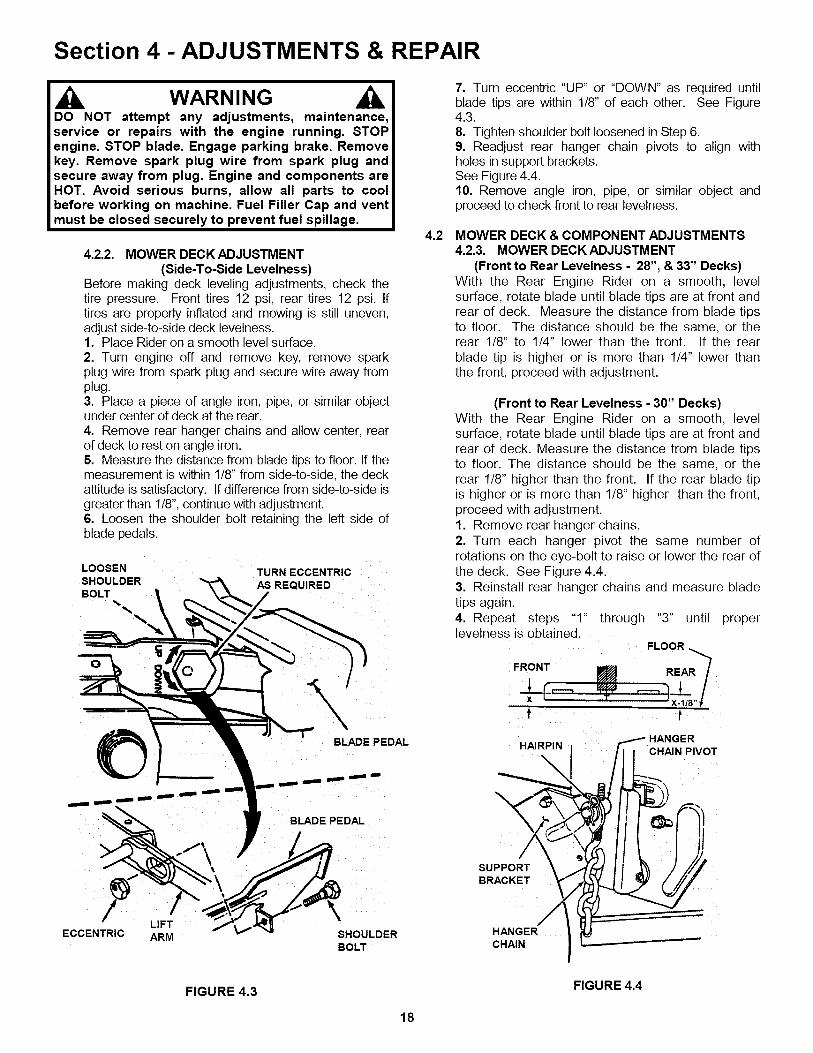
4.2.1. BLADE BRAKE ADJUSTMENTThe automatic Blade Brake should stop the bladeswithin 3 seconds anytime the blades aredisengaged by moving blade lever to the "OFF"position or by releasing the Blade Pedals. Whenthe Blade Brake is properly adjusted there shouldbe 1/8" to 1/4" clearance between the BladeEngagement Lever and the back of the LatchPlate. Check this by disengaging the Blade Leverand depressing the Blade Pedals as shown inFigure 4.2. If clearance is greater than 1/4"perform the following adjustment.1. Remove Belt Cover. Refer to Section "BLADEBELT COVER REMOVAL".2. With the blade engagement lever disengaged,hold the blade pedals down and measure thedistance between the front of the blade lever and therear of the latch plate. The dimension should be 1/8_'to 1/4" clearance between lever and plate. SeeFigure 4.2. If the dimension is incorrect go to step 3.3. If dimension is greater than 1/4", rotate nutclockwise to increase brake tension. If dimensionis less than 1/8", rotate nut counter-clockwise todecrease brake tension. See Figure 4.1.4. Reinstall belt cover.
ROTATE NUT CLOCKWISE TOINCREASE BRAKE TENSION,
ROTATE NUT COUNTER-CLOCKWISE TO DECREASEBRAKE TENSION.
FIGURE 4.1
BLADE ENGAGEMENT LEVER
TO 1/4" DIMENSION
NOTE:BLADE PEDALS LATCHARE ENGAGED PLATE
FIGURE 4.2
(Continued on Next Page)
17
Section 4 - ADJUSTMENTS & REPAIR
WARNINGDO NOT attempt any adjustments, maintenance,service or repairs with the engine running. STOPengine. STOP blade. Engage parking brake. Removekey. Remove spark plug wire from spark plug andsecure away from plug. Engine and components areHOT. Avoid serious burns, allow all parts to coolbefore working on machine. Fuel Filler Cap and ventmust be closed securely to prevent fuel spillage.
4.2.2. MOWER DECK ADJUSTMENT(Side-To-Side Levelness)
Before making deck leveling adjustments, check thetire pressure. Front tires 12 psi, rear tires 12 psi. Iftires are properly inflated and mowing is still uneven,adjust side-to-side deck levelness.1. Place Rider on a smooth level surface.2. Turn engine off and remove key, remove sparkplug wire from spark plug and secure wire away fromplug.3. Place a piece of angle iron, pipe, or similar objectunder center of deck at the rear.4. Remove rear hanger chains and allow center, rearof deck to rest on angle iron.5. Measure the distance from blade tips to floor. If themeasurement is within 118"from side-to-side, the deckattitude is satisfactory. If difference from side-to-side isgreater than 118",continue with adjustment.6. Loosen the shoulder bolt retaining the left side ofblade pedals.
LOOSEN TURN ECCENTRIC
SHOULDER AS REQUIREDBOLT
O
XBLADE PEDAL
4.2
7. Turn eccentric "UP" or "DOWN" as required untilblade tips are within 1/8" of each other. See Figure4.3.8. Tighten shoulder bolt loosened in Step 6.9. Readjust rear hanger chain pivots to align withholes in support brackets.See Figure 4.4.10. Remove angle iron, pipe, or similar object andproceed to check front to rear levelness.
MOWER DECK & COMPONENT ADJUSTMENTS4.2.3. MOWER DECK ADJUSTMENT
(Front to Rear Levelness - 28", & 33" Decks)With the Rear Engine Rider on a smooth, levelsurface, rotate blade until blade tips are at front andrear of deck. Measure the distance from blade tipsto floor. The distance should be the same, or therear 118" to 1/4" lower than the front. If the rearblade tip is higher or is more than 1/4" lower thanthe front, proceed with adjustment.
(Front to Rear Levelness - 30" Decks)With the Rear Engine Rider on a smooth, levelsurface, rotate blade until blade tips are at front andrear of deck. Measure the distance from blade tipsto floor. The distance should be the same, or therear 118" higher than the front. If the rear blade tipis higher or is more than 1/8" higher than the front,proceed with adjustment.1. Remove rear hanger chains.2. Turn each hanger pivot the same number ofrotations on the eye-bolt to raise or lower the rear ofthe deck. See Figure 4.4.3. Reinstall rear hanger chains and measure bladetips again.4. Repeat steps "1" through "3" until properlevelness is obtained.
FLOOR
FRONT m REA "
x ,, -- 'x-1/8"!f t
HANGERHAIRPIN CHAIN PIVOT
BLADE PEDAL
f
ECCENTRICLIFTARM SHOULDER
BOLT
SUPPORTBRACKET
HANGERCHAIN
FIGURE 4.3 FIGURE 4.4
18
Section 4 - ADJUSTMENTS & REPAIR
WARNINGDO NOT attempt any adjustments, maintenance,service or repairs with the engine running. STOPengine. STOP blade. Engage parking brake. Removekey. Remove spark plug wire from spark plug andsecure away from plug. Engine and components areHOT. Avoid serious burns, allow all parts to coolbefore working on machine. Fuel Filler Cap and ventmust be closed securely to prevent fuel spillage.
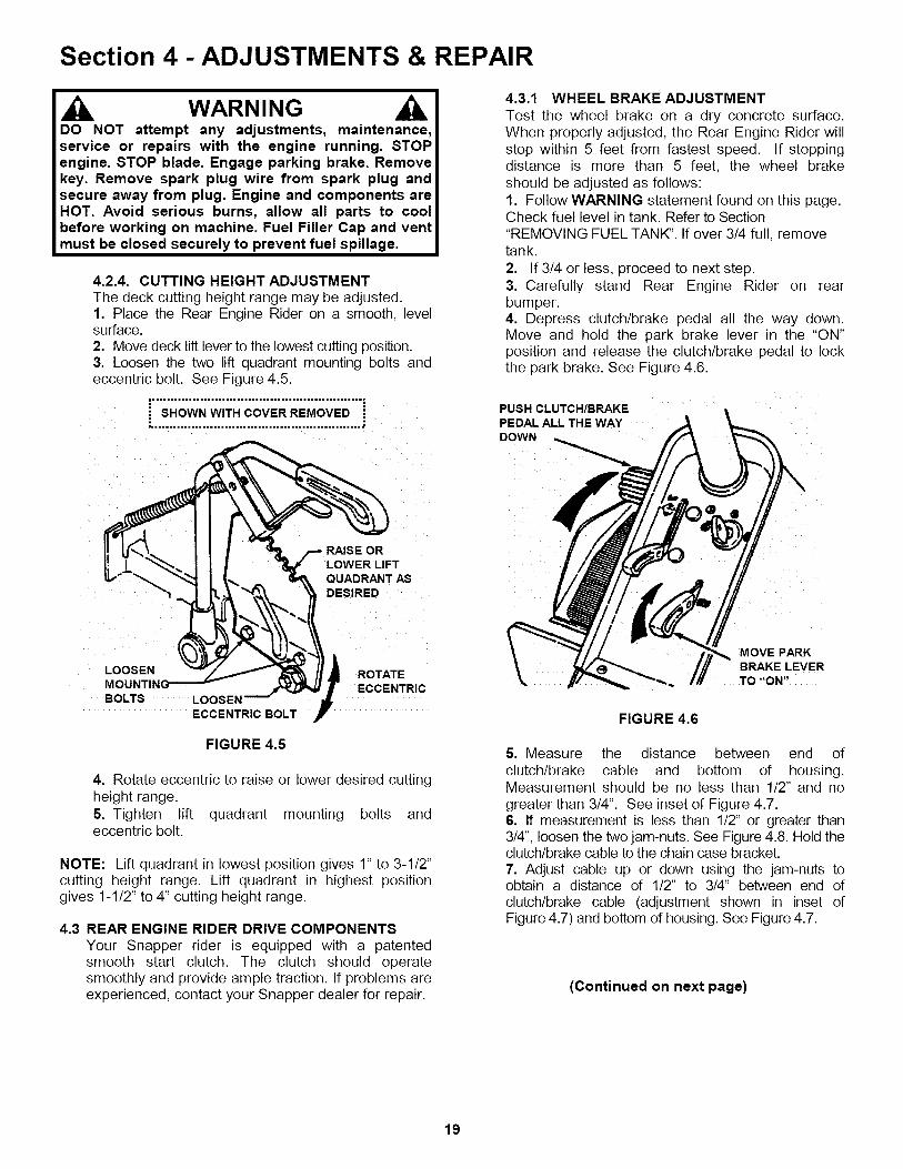
4.2.4. CUTTING HEIGHT ADJUSTMENTThe deck cutting height range may be adjusted.1. Place the Rear Engine Rider on a smooth, levelsurface.2. Move deck lift lever to the lowest cutting position.3. Loosen the two lift quadrant mounting bolts andeccentric bolt. See Figure 4.5.
• SHOWN WITH COVER REMOVED "
4.3.1 WHEEL BRAKE ADJUSTMENTTest the wheel brake on a dry concrete surface.When properly adjusted, the Rear Engine Rider willstop within 5 feet from fastest speed. If stoppingdistance is more than 5 feet, the wheel brakeshould be adjusted as follows:1. Follow WARNING statement found on this page.Check fuel level in tank. Refer to Section"REMOVING FUEL TANK". If over 3/4 full, removetank.
2. If 3/4 or less, proceed to next step.3. Carefully stand Rear Engine Rider on rearbumper.4. Depress clutch/brake pedal all the way down.Move and hold the park brake lever in the "ON"position and release the clutch/brake pedal to lockthe park brake. See Figure 4.6.
PUSH CLUTCH/BRAKEPEDAL ALL THE WAYDOWN
RAISE ORLOWER LIFT
QUADRANT ASDESIRED
LOOSENMOUNTII_BOLTS LOOSEN
ECCENTRIC BOLT
ROTATEECCENTRIC
FIGURE 4.5
4. Rotate eccentric to raise or lower desired cuttingheight range.5. Tighten lift quadrant mounting bolts andeccentric bolt.
NOTE: Lift quadrant in lowest position gives 1" to 3-1/2"cutting height range. Lift quadrant in highest positiongives 1-1/2" to 4" cutting height range.
4.3 REAR ENGINE RIDER DRIVE COMPONENTSYour Snapper rider is equipped with a patentedsmooth start clutch. The clutch should operatesmoothly and provide ample traction. If problems areexperienced, contact your Snapper dealer for repair.
MOVE PARKBRAKE LEVERTO "ON"
FIGURE 4.6
5. Measure the distance between end ofclutch/brake cable and bottom of housing.Measurement should be no less than 1/2" and nogreater than 3/4". See inset of Figure 4.7.6. If measurement is less than 112"or greater than314", loosen the two jam-nuts. See Figure 4.8. Hold theclutch/brake cable to the chain case bracket.7. Adjust cable up or down using the jam-nuts toobtain a distance of 112" to 3/4" between end ofclutch/brake cable (adjustment shown in inset ofFigure 4.7) and bottom of housing. See Figure 4.7.
(Continued on next page)
19

Section 4 - ADJUSTMENTS & REPAIR
_IL WARNINGDO NOT attempt any adjustments, maintenance,service or repairs with the engine running. STOPengine. STOP blade. Engage parking brake. Removekey. Remove spark plug wire from spark plug andsecure away from plug. Engine and components areHOT. Avoid serious burns, allow all parts to coolbefore working on machine. Fuel Filler Cap and ventmust be closed securely to prevent fuel spillage.
4.3.1 WHEEL BRAKE ADJUSTMENT
(Continued from previous page)8. After adjustment is complete, securely tighten cablejam-nuts.
CHAIN
CABLE
HOUSING
CABLEEYE
COTTERPIN
1/2" TO 3/4"
BRAKE CABLE
\
FIGURE 4.7
OUSING
COTTER PIN
CHAIN
LOOSENJAM NUTS
FIGURE 4.8
20

Section 4 - ADJUSTMENTS & REPAIR
WARNINGDO NOT attempt any adjustments, maintenance,service or repairs with the engine running. Stopengine. Stop blade. Engage parking brake. Removekey. Remove spark plug wire from spark plug andsecure away from plug. Engine and components areHOT. Avoid serious burns, allow all parts to coolbefore working on machine. Fuel Filler Cap and Ventmust be closed securely to prevent fuel spillage. DONOT use a cutting blade that shows signs ofexcessive wear or damage. On Rear Engine Ridersequipped with a grass catcher attachment, the airlifts should be replaced when the blade is replaced.
5. Inspect condition of blade. See Figure 4.9.6. If blade is in good condition, sharpen at 22 to 28degrees. DO NOT sharpen beyond existing cuttingedge. See Figure 4.11.7. Check blade balance after sharpening. Ifnecessary, correct blade balance by grinding theheavy end of blade.8. Reinstall blade. See Figure 4.10. Torque blademounting bolts to recommended range of 30 to 40ft. Ibs.
NUT LOCKWASHER
4.4 MOWER BLADE REPLACEMENT4.4.1. BLADE WEAR LIMITS1. Inspect blade frequently for signs of excessivewear or damage. See Figure 4.9.
NEWB DE
I
•---._ _ DANGEROUS CONDITION!
DO NOT USE ON MOWER!REPLACE WITH NEWBLADE.
FIGURE 4.9
WARNING AIWear heavy leather gloves when handling or working Iaround cutting blades. Blades are extremely sharp and Ican cause severe injury. DO NOT use a cutting blade Ithat shows signs of excessive wear or damage. I
4.4.2. BLADE SHARPENING1. Follow WARNING statement found on this page.2. Check fuel level in tank. If over 3/4 full, removetank. Refer to Section "REMOVING FUEL TANK". If3/4 or less, proceed to next step.3. Carefully stand Rear Engine Rider on rear bumper.4. Remove blade. See Figure 4.10.
DO NOT SHARPENBEYONDORIGINALCUTTING EDGE
'BLADE
BLADEMOUNTINGBOLTS
FIGURE 4.10
TO28o__""22 ° X
BLADE TIP /
/
qAL CUTTING EDGE
FIGURE 4.11
21

Section 4 - ADJUSTMENTS & REPAIR
WARNINGDO NOT attempt any adjustments, maintenance,service or repairs with the engine running. STOPengine. STOP blade. Engage parking brake. Removekey. Remove spark plug wire from spark plug andsecure away from plug. Engine and components areHOT. Avoid serious burns, allow all parts to coolbefore working on machine. Fuel Filler Cap and ventmust be closed securely to prevent fuel spillage.
4.5 MOWER DRIVE BELT REPLACEMENTInspect mower drive belt as described in Section"CHECK MOWER DRIVE BELT", Replace belt if signsof excessive wear andlor damage are present,
4.5.1. BELT REMOVAL1. Remove mower drive belt cover. ReferSection "DRIVE BELT COVER REMOVAL".2. Remove old belt.
to
4.5.2. BELT REPLACEMENT1. Follow WARNING statement found on this page.2. Check fuel level in tank. If over 3/4 full, removetank. Refer to Section "REMOVING FUEL TANK". If3/4 or less, proceed to next step.3. Carefully stand Rear Engine Rider on rear bumper.4. Route new belt through engine belt guide up toengine pulley.
ENGINE PULLEY
ENGINEBELTGUIDE
9. Route belt onto spindle pulley. Make sure belt isinside belt guide. Route belt as shown for the individualmodels shown in Figure 4.14.10. Reinstall fixed idler removed in Step 8. Tightenidler pulley bolt securely.
BELT MUST BE TO THE INSIDE OF BELT GUIDE
PULLEY
FIGURE 4.13
BELTGUIDE
11. Adjust belt guide. See Figure 4.14 for proper belt-to-belt guide clearances.
12. Reinstall mower drive belt cover.
28"_ 30" & 33" MODELS
_MINAL (Dual Idler System)
FIGURE 4.25
FIGURE 4.12
5. Move transmission shift lever to the neutral (N)position.6. Rotate clutch yoke (clutch yoke shown in Figure4.7) out with your hand and work belt between drivedisc and rubber driven disc.7. To clear the primary chain case, movetransmission shift lever to the #5 position. Routebelt around drive disc and into drive pulley beltgroove. See Figure 4.12.8. Remove fixed idler. Make sure belt is inside beltguide and idler belt guide. See Figure 4.13.
22

Section 4 - ADJUSTMENTS & REPAIR
WARNINGDO NOT attempt any adjustments, maintenance,service or repairs with the engine running. Stopengine. Stop blade. Engage parking brake. Removekey. Remove spark plug wire from spark plug andsecure away from plug. Engine and components areHOT. Avoid serious burns, allow all parts to coolbefore working on machine. Fuel Filler Cap and Ventmust be closed securely to prevent fuel spillage. DONOT attempt to service or charge the battery while itis installed on the machine.
RED
POSITIVE (+)CABLE "'_
BLACK
NEGATIVE (-)CABLE
POSITIVE TERMINALINSULATOR
4.6 BATTERY4.6.1. BATTERY REMOVAL1. Carefully pull each side of battery cover awayfrom ratchet fasteners and remove cover SeeFigure 4.15.
BATTERY COVER
RATCHETFASTENERS
!FIGURE 4.15
2. Remove the hair pin and swivel from the decksupport to allow clearance for battery removal.3. Slide battery from battery box to gain access toterminal cables.4. Observe and note cable positions on battery.See Figure 4.16.5. Disconnect cables from battery terminals,disconnecting BLACK (Negative) cable first. Retainmounting bolts and nuts.
INSTALL BATTERY POSITIVE
(+) END FIRST INTO BATTERYCOMPARTMENT IN DIRECTIONOF ARROW AS SHOWN
FIGURE 4.16
WARNINGCables must be connected to battery terminals in theproper position as show in Figure 4.16. DO NOTattempt to charge battery while installed on the RearEngine Rider. DO NOT use "BOOST" chargers on thebattery.
4.6.2. BATTERY INSTALLATION1. Slide battery partially into battery housing.2. Connect positive (+) cable (red) first, fromwiring harness to the positive terminal (+) onbattery using bolt and nut provided in hardwarebag. Connect negative (-) cable (black) last, tonegative terminal (-) on battery using bolt and nut.Apply a small amount of grease over terminals toprevent corrosion.3. Reinstall positive terminal insulator.4. Insert battery completely into battery housing.5. Reinstall battery cover. See Figure 4.15.6. Reinstall swivel and hair pin for deck support.
23

Section 4 - ADJUSTMENTS & REPAIR
WARNINGThe electrolyte (acid) produces a highly explosive gas.Keep all sparks, flame and fire away from area whencharging battery or when handling electrolyte orbattery. Electrolyte (acid) is a highly corrosive liquid.Wear eye protection. Wash affected areas immediatelyafter having eye or skin contact with electrolyte (acid).Battery acid is corrosive. Rinse empty acid containerswith water and mutilate before discarding. If acid isspilled on battery, bench, or clothing, etc., Flush withclear water and neutralize with baking soda. DO NOTattempt to charge battery while installed on the RIDER.DO NOT use "BOOST" chargers on the battery.
4.6.3. BATTERY SERVICE1. Remove battery. Refer to Section "BATTERYREMOVAL".2. Place battery in a well ventilated area on a levelsurface.3. Using distilled water, refill cells as required tocover cell plates of which can also be visualizedthrough the plastic battery case.4. With cell caps removed, connect battery chargerto battery terminals. Red to positive (+) terminaland black to negative (-) terminal.5. Slow charge battery at 1 amp for 10 hours.6. If battery will not accept charge or is partiallycharged after 10 hours of charging at 1 amp,replace with new battery.
4.6.4. BATTERY STORAGEIf mower is to be stored out of season on its rearbumper, it is recommended the battery be removed,charged and stored.1. Remove battery. Refer to Section "BATTERYREMOVAL".2. Perform battery service.3. Bring battery to full charge, if required.4. Store battery in an area away from the RIDER on awood surface. DO NOT STORE BATTERY ON ACONCRETE SURFACE.
4.6.5. NEW BATTERY PREPARATION1. Remove battery from carton.2. Place battery in a well ventilated area on a levelnon-concrete surface.3. Remove battery cell caps. Fill cells as requiredwith electrolyte (purchased separately) to properlevel. Fill to 3/16" above cell plates. Filling batterywith electrolyte will bring the battery to 80% chargedstate.4. With cell caps removed, connect battery charger tobattery terminals; RED to positive (+) and BLACK tonegative (-) terminal.
IMPORTANT: 3/16" above cell plates is the recommendedlevel. DO NOT place anything in battery other than specifiedelectrolyte.
lj , WARNINGDO NOT attempt to charge battery while installed on the IRiding Mower. DO NOT use "BOOST" chargers on thebattery. DO NOT OVERFILL! I
5. Slow charge the battery at 1 amp for 2 hours tobring the battery to full charge.6. After charging, check level of electrolyte and addas needed to bring level to 3/16" above cell plates.7. Reinstall cell caps.8. Remove the hair pin and swivel from the decksupport to allow clearance for battery installation.9. Slide battery partially into battery housing.10. Connect positive (+) cable (red) first, from wiringharness to the positive terminal (+) on battery usingbolt and nut provided in hardware bag. Connectnegative (-) cable (black) last, to negative terminal (-)on battery using bolt and nut. Apply a small amount ofgrease over terminals to prevent corrosion.11. Insert battery completely into battery housing.12. Reinstall battery cover. See Figure4.15.13. Reinstall swivel and hair pin for deck support.
4.6.6. BATTERY TESTINGThere are two types of battery tests: Unloaded andLoaded. The unloaded test is the procedure that willbe discussed. It's the simplest and most commonlyused. An unloaded test is made on a battery withoutdischarging current. To perform unloaded testing,check charge condition using either a hydrometer orvoltmeter.1. Using a voltmeter, voltage readings appearinstantly to show the state of charge. Remember tohook the positive lead to the battery's positiveterminal, and the negative lead to the negativeterminal.2. A hydrometer measures the specific gravity ofeach cell. The specific gravity tells the degree ofcharge; generally, a specific gravity of about 1.265to 1.280 indicates full charge. A reading of 1.230 to1.260 indicates the battery should be charged. Thechart on the next page shows the charge level asmeasured by syringe float hydrometer, digitalvoltmeter and five ball hydrometer.
Shield the positive terminal with terminal cover Ilocated on battery harness. This prevents metal fromtouching the positive terminal which could cause lsparks. I
(Battery Testing Chart on Next Page)
24

Section 4 - ADJUSTMENTS & REPAIR
4.6.6. BATTERY TESTING
State of Charge
100% Charged w/Sulfate Stop100% Charged75% Charged50% Charged25% Charged0% Charged
Batten/Condition ChartSyringe Hydrometer
1.2801.2651.2101.1601.120
Less than 1.100
Digital Voltmeter12.80v12.60v12.40v12.10v11.90v
Less than 11.80v
Five Ball Hydrometer
Five Balls FloatingFour Balls FloatingThree Balls FloatingTwo Balls FloatingOne Ball FloatingZero Balls Floating
SNAPPER REAR ENGINE RIDER ACCESSORIES
PART NO. DESCRIPTION OF KIT MODELS USED ON
6-0517 ..............................6-0601 ..............................6-0697 ..............................6-1400 ..............................
..Wheel Weight (8" Wheels) ............................... All Rear Engine Riders
..Smooth Start Clutch .......................................... All Rear Engine Riders
.. Dump Cart ......................................................... All Rear Engine Riders
..Gauge Wheel .................................................... All 33" Deck Rear Engine Riders
6-0794 ..............................6-0941 ..............................6-0942 ..............................6-0943 ..............................
..Gauge Wheel .................................................... All 41"& 42" Deck Rear Engine Riders
..Single Bag Catcher ........................................... All 25" Deck Rear Engine Riders
..Single Bag Catcher ........................................... All 26" & 30" Deck Rear Engine Riders
..Single Bag Catcher ........................................... All 28" & 33" Deck Rear Engine Riders
6-0944 ..............................6-0945 ..............................6-0946 ..............................6-0947 ..............................
..Single Bag Catcher ........................................... All 41"& 42" Deck Rear Engine Riders
..Twin Bag Catcher ............................................. All 41" & 42" Deck Rear Engine Riders
..Twin Bag Catcher ............................................. All 28" & 33" Deck Rear Engine Riders
.. Bag-N-Wagon ................................................... All 28" & 33" Deck Rear Engine Riders
6-0948 ................................ Thatcherizer ...................................................... All Series 7 & Newer Riders6-0964 ................................ Wagon Cover .................................................... All 28" & 33" Deck Rear Engine Riders6-1190 ................................ Weight (Front) ................................................... All Series 7 & Newer Riders6-0959 ................................ Dozer Blade (36" Blade) .................................... All Rear Engine Riders
6-0357 ................................ Tire Chains (Tires-16 x 6.50-8) ......................... All6-0358 ................................ Tire Chains (Tires-16 x 4.80-8) ......................... All6-1823 ................................ Ninja Recycling (Cover) .................................... All6-1049 ................................ Recycling (Cover) .............................................. All
Rear Engine RidersRear Engine Riders25" Deck Rear Engine Riders25" Deck Rear Engine Riders
6-1253 ..............................6-1254 ..............................6-1255 ..............................6-1987 ..............................
.. Ninja Recycling (Cover) .................................... All 28" Deck Rear Engine Riders
.. Ninja Recycling (Cover) .................................... All 30" Deck Rear Engine Riders
.. Ninja Recycling (Cover) .................................... All 33" Deck Rear Engine Riders
.. Ninja Recycling (Cover) .................................... All 41" & 42" Deck Rear Engine Riders
6-1910 ................................ Utility Trailer6-1911 ................................ Aerator6-1912 ................................ Dethatcher6-1913 ................................ Lawn Sweeper
6-1914 ................................ Dethatcher Kit6-1915 ................................ Lawn Roller6-1916 ................................ Broadcast Spreader
25

PROBLEMEngineWill Not
Start UsingRecoil Starter
Engine Will NotStart Using
Electric Starter
TROUBLESHOOTING
,
2.3.4.5.6.1.2.3.4.5.6.
PROBABLE CAUSE
Fuel tank empty. 1.Engine needs choking. 2.Spark plug wire disconnected. 3.Faulty parking brake, blade or ignition switch. 4.Park brake not engaged. 5.Ignition is in the OFF position. 6.
Fuel tank empty. 1.Engine needs choking. 2.Spark plug wire disconnected. 3.Faulty parking brake, blade or ignition switch. 4.Park brake not engaged. 5.Blown Fuse. 6.
CORRECTIVE ACTION
Fill fuel tank with fresh fuel to proper level.Move choke control to "CHOKE" position.Place spark plug wire onto spark plug.Contact authorized SNAPPER dealer.Engage park brake.Turn ignition switch to the RUN position.
Fill fuel tank with fresh fuel to proper level.Move choke control to "CHOKE" position.Place spark plug wire onto spark plug.Contact authorized SNAPPER dealer.
Engage park brake.Replace with new 20 AMP fuse.
7. Faulty interlock module. 7. Contact authorized SNAPPER dealer.8. Ignition is in the OFF position. 8. Turn ignition switch to the START position.9.Battery is weak or dead. 9. Charge or replace with new battery.10. Battery cables loose, broken disconnected or
corroded.
11. Faulty electric starter or starter solenoid.12. Starter cable loose, broken or disconnected
13. Electrical wiring harness disconnected or broken.
Engine Stalls After 1. Operator not in seat.Running 2. Choke control in the "CHOKE" position.
3. Fuel tank empty.4. Engine air pre-cleaner and or air cleaner dirty. 4. Clean free of all debris.5. Spark plug defective or gap set improperly. 5. Service spark plug.6. Fuel filter restricted. 6. Replace fuel filter.7. Water, debris or stale fuel in fuel system. 7. Drain and clean fuel system.
Engine Loses 1. Excessive load on engine. 1. Lessen load.Power 2. Engine air pre-cleaner or air cleaner dirty 2. Clean or replace filters.
3. Spark plug faulty. 3. Service spark plug.4. Water, debris or stale fuel in fuel system. 4. Drain and clean fuel system. Replace filter.5. Debris build up on engine cooling screen. 5. Clean all debris from engine cooling screen.
Engine Backfires 1. Throttle control set too "FAST". 1. Set throttle control to "SLOW" and allowWhen Turned To engine to idle. Then, turn key to "OFF".
"STOP"
Excessive Vibration 1. Damaged, out of balance or bent mower blades. 1. Service mower blade(s).2. Loose blade components. 2. Service and tighten loose parts.3. Loose or missing air lift (if equipped). 3. Replace air lifts. Tighten to proper torque.4. Lumpy or frayed belt 4. Replace belt.5. Bent Idler, stationary or spindle pulley 5. Replace pulley.
10. Clean and connect battery cables. Ifbroken, replace with new battery cables.
11. Contact authorized SNAPPER dealer.12. Connect starter cable. If broken, replace
with new starter cable.
13. Connect or replace with new wiring harness.
1. Sit in operator's seat.2. Move choke control to "OFF" position.3. Fill fuel tank with fresh fuel to proper level.
(Trouble Shooting Continued on Next Page)
26

PROBLEM
Rider Will Not MoveLoss Of Traction
Blade(s) Not Cutting
Cutting GrassImproperly
Poor Grass
Discharge
TROUBLESHOOTING
CORRECTIVE ACTION
Replace drive disc.Adjust rubber drive disc.
PROBABLE CAUSE
1. Drive disc worn or dama,qed. 1.2. Rubber drive disc is not tracking properly on 2.
drive disc.3. Tapered axle bolt and nut missing. 3.4. Axle bearing seized. 4.5. Insufficient lubrication in chain case or 5.
transmission/differential.
1. Blade engagement lever in the "OFF" position. 1.2. Mower belt slipping. 2.3. Cutting blade is dull, worn or damaged. 3.1. Uneven tire pressure. 1.
2. Cutting height too low or high. 2.3. Engine speed too slow. 3.4. Forward speed too fast. 4.
5. Terraced cut, side to side. 5.
6. Excessive deck pitch, front to rear. 6.7. Cutting blade(s) dull or damaged. 7.8. Mower belt slipping. 8.1. Engine speed too slow. 1.2. Forward speed too fast. 2.
3. Grass is wet. 3.
4. Excessively dull, worn or damaged blade(s). 4.5. Build up of grass clippings and debris under 5.
deck.
6. Improper blade installed on deck. 6.1. Leaking chain case or differential plugs. 1.
2. Leaking engine block. 2.
Replace with SNAPPER tapered bolt & nut.Contact authorized SNAPPER dealer.Contact authorized SNAPPER dealer.
Move lever to the "ON" position.Adjust or replace mower belt.Sharpen or replace cutting blade.Bring to proper pressure. 12 PSI front tire& 12 PSI rear tire.
Adjust cutting height.Move throttle control to "FAST" position.Move transmission shift lever to a slowerspeed.
Adjust side to side levelAdjust front to rear pitch.Sharpen cutting edges or replace blade(s).Adjust tension or replace mower belt.Move throttle control to "FAST" position.Move transmission shift lever to a slowerspeed.Mow when grass is dry.Service mower bladeClean the underside of deck.
Install proper SNAPPER blades.
Oil Leaking Verify plugs are not cracked & are in goodshape. Check gaskets.Contact authorized SNAPPER dealer.
27

MAINTENANCE SCHEDULE
SUBJECT
Engine
Engine
Engine
Air Pre-Cleaner
Air Cleaner
Spark Plug
Fuel Filter
Engine CoolingSystemBattery
Battery
Tires
Drive Belts
Mower Blades
Mower Deck
Lubrication Points
Lubricate Chain Case& TransmissionBlade Brake
Stopping TimeClutch/Brake System
SERVICETO BE PERFORMED
Check Oil Level
Initial Oil Change
Periodic Oil Change
Service Sponge Pre-Cleaner Element
Replace Element
Replace Plugs
Replace Filter
Clean Shrouds & Fins
Check Electrolyte
Charge Battery
Check Pressures
Check For Wear AndTensionCheck For Wear AndDamageClean DebrisAccumulationGrease or Oil
Check Grease Level
Check blade stoppingfor proper operationCheck Clutch/Brake forproper operation
REFERENCEPAGES
Page 6
Page 12
Page 13
Engine Manual
Engine Manual.
Engine Manual.
Page 16
Engine Manual
Page 24
Page 23 & 24
Page 6
Pages13,17,22
Pages 21
EACHUSE
X
X
Page 12 & 14 X
Pages 14 & 15
Pages 14 & 15
Pages 9, 10, 11 X&17
Page 7- 8 X
6HOURS
X
26HOURS
X
X
X
X
X
60HOURS
X*
*Change oil every 25 hours when operating under heavy load or high temperatures.**Clean more often under dusty conditions or when air debris is present
100HOURS
X
X
X**
X
EACHSEASON
X
X
X
X
X
X
X
X
28

MAINTENANCE/REPLACEMENT PARTS
MAINTENANCE PARTSEngine Speed Control (Briggs Engine)Engine Speed Control (Kohler Engine)Clutch/Brake CableBrake Cable
28" Cutter Blade IStandard - Not Air Lift Compatible)28" Cutter Blade (Standard - Air Lift Compatible)
28" Cutter Blade IMulchin_)
2-41552-24832-99132-23443-56351-95151-6980
28" Cutter
30" Cutter
30" Cutter
30" Cutter
33" Cutter
33" Cutter
33" Cutter
33" Cutter
Air Lift Kit
Blade (Ninja - Quad Edge)
Blade IStandard - Not Air Lift Compatible)Blade (Standard - Air Lift Compatible)
Blade INinia - Quad Eddie)Blade (Standard - Not Air Lift Compatible)
Blade IStandard - Air Lift Compatible)Blade (Mulching)
Blade INinia - Quad Eddie)(28" & 33" Decks)
Air Lift Kit 130" Decks)Engine to Cutting Deck BeltRubber Drive Disc
Parts Manual for Rear Engine Rider Series 16 & 18
2-6453N/A
1-80692-65653-41681-95231-69822-47416-04806-07352-22525-310306098
29
3 YEAR LIMITED WARRANTY
For three (3) years from purchase date for the original purchaser's residential, non-commercial use, SNAPPER, throughany authorized SNAPPER dealer will replace, free of charge (except for taxes where applicable), any part or parts foundupon examination by the factory at McDonough, Georgia, to be defective in material or workmanship or both.
For ninety (90) days from purchase date for the original purchaser's commercial, rental, or other non-residential use,SNAPPER, through any authorized SNAPPER dealer will replace, free of charge, any part or parts found uponexamination by the factory at McDonough, Georgia, to be defective in material or workmanship or both.
All transportation costs incurred by the purchaser in submitting material to an authorized SNAPPER dealer forreplacement under this warranty must be paid by the purchaser.
This warranty does not apply to engines and their components, and batteries, as these items are warranted separately.This warranty does not apply to parts that have been damaged by accident, alteration, abuse, improper lubrication,normal wear, or other cause beyond the control of SNAPPER. This warranty does not cover any machine or componentpart that has been altered or modified changing safety, performance, or durability.
Batteries have a one (1) year prorated warranty period with free replacement if required during the first ninety (90) daysfrom the original purchase date. SNAPPER will not be responsible for any installation cost incurred. The battery warrantyonly covers original equipment batteries and does not cover damage to the battery or machine caused by neglect orabuse, destruction by fire, explosion, freezing, overcharging, improper maintenance, or use of improper electrolyte.
There is no other express warranty.
DISCLAIMER OF WARRANTYImplied warranties, including those of merchantability and fitness for a particular purpose, are limited to three(3) years from purchase date for the original purchaser's residential or other non-commercial use, and ninety(90) days from purchase for the original purchaser's commercial, rental or other non-residential use, and to theextent permitted by law, any and all implied warranties are excluded. This is the exclusive remedy. Liabilities forconsequential damages, under any and all warranties are excluded.
Some states do not allow limitations on how long an implied warranty lasts, or do not allow the exclusion orlimitation of incidental or consequential damages, so the above limitation or exclusion may not apply to you.
This warranty gives you specific legal rights, and you may also have other rights which vary from state to state.
WARNING: THE USE OF REPLACEMENT PARTS OTHER THAN GENUINE SNAPPER PARTS MAY IMPAIR THESAFETY OF SNAPPER PRODUCTS AND WILL VOID ANY LIABILITY AND WARRANTY BY SNAPPERASSOCIATED WITH THE USE OF SUCH PARTS.
IMPORTANT: Please fill out the attached SNAPPER Product Registration Card immediately and mail to:Snapper's Product Registration Center, P.O. Box 1379, McDonough, Georgia 30253
30

PRIMARY MAINTENANCE
®
an
illustration ofhow dirt can
[e& how
maintenancecan protect it!
Snapper uses the best avail-able engines and components nIn their products in order to 4;provide long, satisfactoryservice. However, propercare is essential In _"prolonging engine life. DirtIs your engine's enemynumber 11
The engine on your Snapperproduct spends Its entire lifeoperating close to the ground athigh speed creating a virtualstorm of dust and dlrtl
31

PRIMARY MAINTENANCE
The engine mustgulp about 12,000gallons of air for
°;. °
"; .. o:o
used. Because ofits working environ-ment, the air availableto your Snapper engine Is "heavily saturated with air-borne dirt particles.
g that dirt willquickly ruin an engine,manufacturers equip theirengines with extremelyefficient air cleaners tofilter out the harmful dirt.
As the dirt particles are stopped,they build up and begin to clogthe outside of the filter. Thisreduces the amount of airavailable to the engine and causesan over-rich fuel mixture which re-sults In the following adverseeffects:
An Improperly serviced, dirtclogged air cleaner will:
1. Increase fuel consumption2. cause power loss3. result in hard starting4. create smoke from unburned
fuel5. produce carbon build-up ;
Internally6. foul spark plug electrodes7. score cylinder walls8. burn valves9. wear out the engine pre-
maturely10. COST YOU MONEY!
Damage caused by a poorly serviced aircleaner Is not covered under the enginewarranUes. So, save yourself unnecessaryexpenses and undue aggravation by keepingthe air cleaner properly serviced at the Intervalsspecified In the engine owner's manual.
It doesn't like long to ssrvlce an air cleaner.Follow the specific instructions In the engineowner's manual for the type filter used. Pre-vent dirt from falling Into the carburetor Intakewhen ssrvicing your air cleaner. Make surecomponents are Installed In correct sequenceafter servicing to prevent unfiltered air fromentering the engine. Some servicing hints onseveral common types are:
32

PRIMARY MAINTENANCE
Generally, wash foam-type filtersIn a dlshwashlng detergent andwater solution. Rinse and wringdry, then saturate with oil andsqueeze out excess. Failure tore-oil this type filter will ruin theengine.
Clean paper elements by tappinglightly. Blowing with air willrupture paper elements.
Use a flashlight to detect cloggedor torn paper elements - replace Ifdamaged In any way.
Air Is also needed to keepyour engine cool. Dirt, dust& debris build up to restrictand clog cooling air Intakescreens and fins. Cleanscreens and fins at frequentIntervals. The engine blowerhousing and shrouds shouldbe removed at least onceeach season or more often
t under dry, dusty conditionsfor a thorough cleaning offins.
Failure to keep externalsurfaces clean not onlypresents fire hazards, but
causes overheating andresulting engine damagessuch as:
1. distorted valve guides2. sticking valves
t _°o. 3. scuffed, scored,.,. walls
4. overspeedlng5. loss of power6. complete failure of
engine.
Dirt can also be introducedinto an engine In dirty fuelfrom a contaminatedcontainer. Always use cleanfresh fuel from a cleancontainer to guard againstdirt, sludge and watercontamination.
Be aware that fuel breaksdown in storage and formsgummy compounds whichwill block carburetor pass-ages. Never use fuel morethan 3 months old. Draintank then run the engine outof fuel before storing duringthe off-season.
An engine must also have proper lubrication.All engines use some oil. On 4-cycle engines,CHECK OIL LEVEL BEFORE EACH START-UP.Wipe area clean around the oll check plug ordipstick opening to keep dirt from falling intothe engine when checking the oil. Alwayscheck with the machine on a level surface.On engines with dipstick, keep the level up to,but not over, the FULL mark. When adding o11,allow time for all of the oll to flow down the filltube to prevent a false full reading when thelevel could actually be low and result In enginedamage.
33
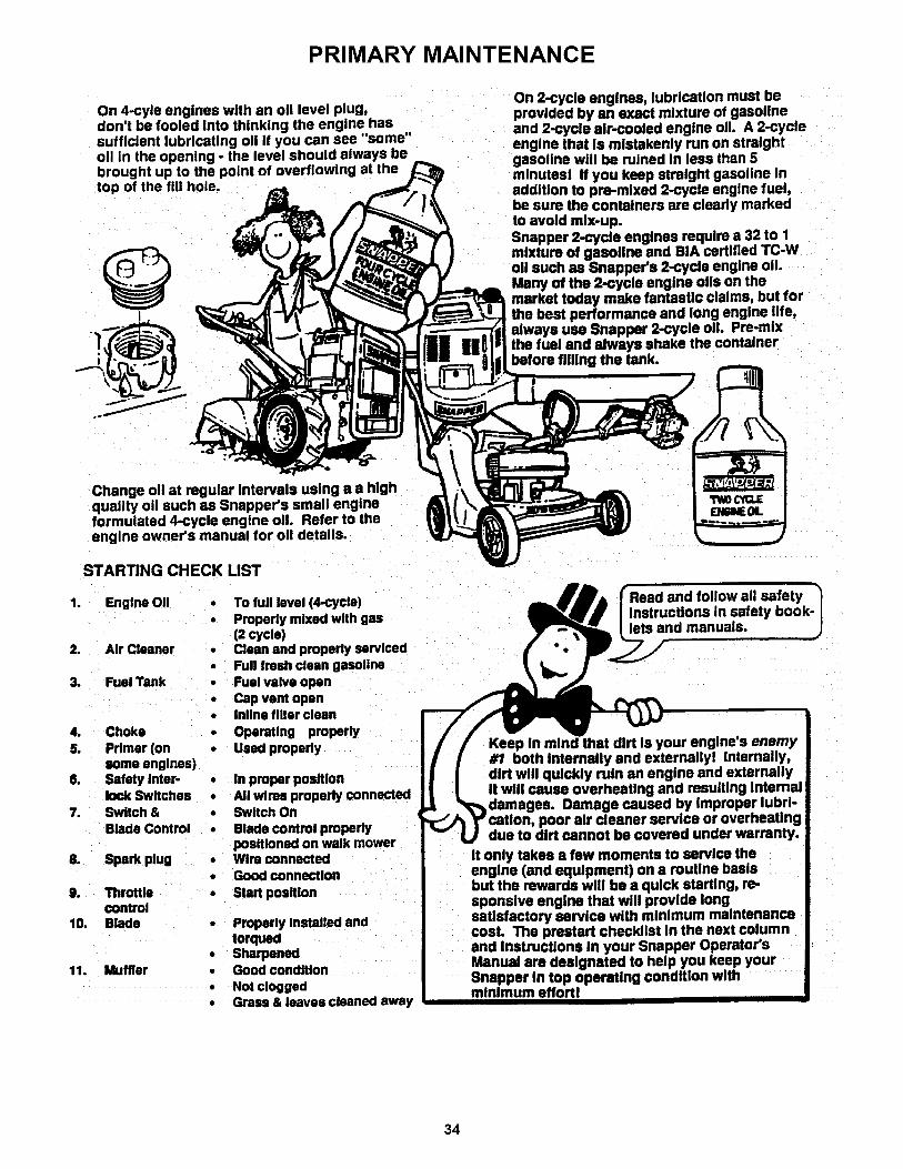
PRIMARY MAINTENANCE
On 4-cyle engines with an oil level plug,don't be fooled into thinking the engine hassufficient lubricating oii if you can see "some"oil in the opening - the level should always bebrought up to the point at thetop of the fill hole.
I
On 2-cycle engines, lubrication must beprovided by an exact mixture of gasolineand 2-cycle air-cooled engine oil A 2-cycleengine that Is mistakenly run on straightgasoline will be ruined in less than 5minutesl If you keep straight gasoline InaddlUon to pre-mixed 2-cycle engine fuel,be sure the containers are clearly markedto avoid mix-up.Snapper 2-cycle engines require a 32 to 1mixture of gasoline and BIA certified TC-Woil such as Snapper's 2-cycle engine o11.Many of the 2-cycle engine oils on themarket today make fantastic claims, but forthe best performance and long engine life,always usa Snapper 2-cycle oil Pre-mixthe fuel and always shake the containerbefore tilting the tank.
Change oil at regular Intervals using a a highquality oil such as Snapper's small engineformulated 4-cycle engine oil Refer to theengine owner's manual for oil details.
STARTING CHECK LIST
1. Engine Oil
2. Air Cleaner
3. Fuel Tank
4. Choke5. Primer (on
some englnes)6. Safety Inter-
lock Switches7. Switch &
Blade Control
8. Spark plug
9. Throttlecontrol
10. Blade
11. Muffler
• To full level (4-cycle)
• Properly mixed with gas(2 cycle)
• Clean and properly serviced• Full fresh clean gasoline• Fuel valve open
• Cap vent open• lnline filter clean
• Operating properly• Used properly
• In proper position• All wires propedy connected• Switch On
• Blade control properlypositioned on walk mower
• Wire connected
• Good connection
• Start position
Properly Installed andtorqued
• Sharpened• Good condition
• Not clogged• Grass & leaves cleaned away
Read and follow all safetyInstructions in safety book-lets and manuals.
Keep in mind that dirt Is your engine's enemy#1 both Internally and externallyl Internally,dirt will quickly ruin an engine and externallyIt will cause overheating and resulting Internal
Damage caused by Improper lubrl-poor air cleaner service or overheating
due to dirt cannot be covered under warranty.
It only takes a few moments to service theengine (and equipment) on a routine basisbut the rewards will be a quick starting, re-sponsive engine that will provide longsatisfactory service with minimum maintenancecosL The prestart checklist In the next columnand Instructions In your Snapper Operator'sManual are designated to help you keep yourSnapper In top operating condition withminimum effortl
34

SERVICE NOTES
35

Safety Instructions & Operator's Manual for
REAR ENGINE RIDING MOWERSERIES 18
IMPORTANTSnapper products are built using engines that meet or exceed all applicable emissions requirements on thedate manufactured. The labels on those engines contain very important emissions information and criticalsafety warnings. Read, Understand, and Follow all warnings and instructions in this manual, the enginemanual, and on the machine, engine and attachments. If you have any questions about your Snapper product,contact your local authorized Snapper dealer or contact Snapper Customer Service at Snapper, McDonough,GA. 30253. Phone: (1-800-935-2967).
I_WARNING:The engine exhaust from this product contains chemicals known to the State Iof California to cause cancer, birth defects or other reproductive harm. I
SNAPPER, McDonough,GA., 30253 U.S.A.
COPYRIGHT © 1999SNAPPER INC.ALL RIGHTS RESERVED
MANUAL No. 4-7008 (REV. 1, 8/20/99)
36