Embed Size (px)
Citation preview

Real-time In-Flight Strain and Deflection Monitoring with Fiber Optic Sensors
Real-time In-Flight Strain and Deflection Monitoring with Fiber Optic Sensors
Nat
iona
l Aer
onau
tics
and
Spa
ce A
dmin
istra
tion
Dr. Lance Richards, Allen R. Parker, Dr. William L. Ko, Anthony PiazzaDryden Flight Research Center, Edwards, CA
Space Sensors and Measurements Techniques WorkshopNashville, TN
August 5, 2008
Dr. Lance Richards, Allen R. Parker, Dr. William L. Ko, Anthony PiazzaDryden Flight Research Center, Edwards, CA
Space Sensors and Measurements Techniques WorkshopNashville, TN
August 5, 2008

2
Nat
iona
l Aer
onau
tics
and
Spa
ce A
dmin
istra
tion
Background• Dryden’s Aerostructures Branch initiated
fiber-optic instrumentation development effort in the mid-90’s
– Dryden effort focused on atmospheric flight applications of Langley patented OTDR demodulation technique
• Dryden collaborated on X-33 IVHM Risk Reduction Experiment on F/A-18 System Research Aircraft
– Focused on validating Lockheed Sanders FO VHM system
• Flew fiber optic instrumented flight test fixture with limited success due to problem with laser
– Lockheed Sanders system limited to 1 sample every 30 seconds
• Dryden initiated a program to develop a more robust / higher sample rate fiber optic system suitable for monitoring aircraft structures in flight
Ground to Flight Fiber-Optic Sensing
Technology Development
X-33 IVHM Risk Reduction Experiment

3
Nat
iona
l Aer
onau
tics
and
Spa
ce A
dmin
istra
tion
Fiber Optic System Operation OverviewFiber Optic Sensing with Fiber Bragg Gratings• Immune to electromagnetic / radio-frequency interference and radiation• Lightweight fiber-optic sensing approach having the potential of embedment
into structures• Multiplex 100s of sensors onto one optical fiber• Fiber gratings are written at the same wavelength• Typical gage lengths from 0.1mm to 100mm • Uses a narrowband wavelength tunable laser
source to interrogate sensors• Typically easier to install than conventional
strain sensors
Reflector Λ Λ Λ
L1
L3L2
Laser lightLoss light
Reflected light(IR )
Laser tuning
start stopλ
∑=i
iiR nLkCosRI )2(Ri – spectrum of ith gratingn – effective indexL – path differencek – wavenumber
λπ2
=k
Grating region
Tuning direction

4
Nat
iona
l Aer
onau
tics
and
Spa
ce A
dmin
istra
tion
Fiber Optic System Operation Overview
• Fourier transforms (both forward and inverse) are used to discriminate between gratings
• The Fourier transform separates the IR waveform into sinusoids of different frequency which sum to the original waveform
FFT iFFT
Traditional Time(T) > Frequency(F) Frequency(F) > Time(T)
Optical Wavelength(λ) > Length(L) Length(L) > Wavelength(λ)
FFT
Wavelength(λ) domain Length(L) domain
Spectral Mapping

5
Nat
iona
l Aer
onau
tics
and
Spa
ce A
dmin
istra
tion
Fiber Optic System Operation Overview
• By bandpass filtering around a specific frequency (grating location) within the length domain and performing an iFFT, the spectrum of each grating can be independently measured and strain inferred (FM radio)
• Using a centroid function the center wavelength can be resolved• The wavelength change is proportional to the induced strain
Length(L) domain (inches)
iFFT
Wavelength(λ) domain
ελλ K=
Δ K – proportionality constant (0.7-0.8)

7
Nat
iona
l Aer
onau
tics
and
Spa
ce A
dmin
istra
tion
Motivation – Helios Mishap
Helios Mishap Report – Lessons Learned
• Measurement of wing dihedral in real-time should be accomplished with a visual display of results available to the test crew during flight
• Procedure to control wing dihedral in flight is necessary for the Helios class of vehicle
Helios wing dihedral on takeoff In-flight breakup

8
Nat
iona
l Aer
onau
tics
and
Spa
ce A
dmin
istra
tion
Wing Shape Sensing Background
• Current Wing Displacement Techniques
– Optical Methods (Flight Deflection Measurement System)
• 1980s - Highly Maneuverable Aircraft Technology (HiMAT)
• 2000s - F/A-18 Active Aeroelastic Wing (AAW)
– Strain Gage Approaches
• Limitations
– Current techniques utilize approaches that are too heavy and not appropriate for weight-sensitive, highly-flexible structures

9
Nat
iona
l Aer
onau
tics
and
Spa
ce A
dmin
istra
tion
• Assess technical viability and, if applicable, develop methodology and approach to incorporate wing shape measurements within the vehicle flight control system (FY08-FY09)
• Develop and flight validate advanced approaches to perform active wing shape control using
• conventional control surfaces (FY09-FY10)
• active material concepts (FY09-FY11+)
Research Objectives for Ikhana
• Flight validate fiber optic sensor measurements and real-time wing shape sensing predictions on NASA’s Ikhana vehicle (FY08)
• Validate fiber optic mathematical models and design tools (FY08)

10
Nat
iona
l Aer
onau
tics
and
Spa
ce A
dmin
istra
tion
– Algorithm Development
– FBG System Development
– Instrumentation
– Ground Testing
– Flight Testing
Research Areas( )
⎭⎬⎫
⎩⎨⎧
+−+−Δ
= ∑−
=
1
10
2
6)13(6
n
inin inn
cly εεε

11
Nat
iona
l Aer
onau
tics
and
Spa
ce A
dmin
istra
tion
Algorithm Development (Ikhana)
Algorithm (Leading-edge Fiber)FEA (LE fiber)Algorithm (Trailing-edge fiber)FEA (TE fiber)
Ikhana Wing Geometry Analytical Models
Computational Models Analytical/Comp. Comparison

12
Nat
iona
l Aer
onau
tics
and
Spa
ce A
dmin
istra
tion
Ikhana Fiber Optic Flight System• Current flight system specifications
– Fiber count 4– Max fiber length 40 ft– Max sensing length 20 ft– Max sensors / fiber 480– Total sensors / system 1920– Sample rate 2 fibers @ 50 sps
4 fibers @ 24 sps– Power 28VDC @ 4 Amps– User Interface Ethernet – Weight (non-optimized) 23 lbs– Size (non-optimized) 7.5 x 13 x 13 in
• Environmental qualification specifications– Shock 8g– Vibration 1.1 g-peak sinusoidal curve – Altitude 60kft at -56C for 60 min– Temperature -56 < T < 40C
Ikhana Avionics Bay
Fiber Optic Flight System
Ikhana in Flight

13
Nat
iona
l Aer
onau
tics
and
Spa
ce A
dmin
istra
tion
Flight Instrumentation
Ikhana in Flight
Optical Fiber
• Instrumentation– 2880 FBG strain sensors (1920 recorded at one time)– 1440 FBG sensors per wing– User-selectable number of FBG sensors for real-time wing shape sensing– 16 strain gages for FBG sensor validation– 8 thermocouples for strain sensor error corrections
FBG systemStrain gage system

14
Nat
iona
l Aer
onau
tics
and
Spa
ce A
dmin
istra
tion
Ikhana in Flight
• Ground validation testing– Conducted ground validation testing January 16-18, 2008– Used Dryden’s high resolution / high speed optical measurement
system as validation standard– 10 measurement stations placed on left wing (1 on center fuselage)– Five load cases applied– Good agreement between FOWSS and optical system
Ground Test Validation - Ikhana
Left wing – aft viewLeft wing – aft view Left wing – inboard view
Optical targetsOptical targets

15
Nat
iona
l Aer
onau
tics
and
Spa
ce A
dmin
istra
tion
Ikhana in Flight
• Flight validation testing– Conducted first flight validation testing April 28, 2008– Believed to be the first flight validation test of FBG strain and wing
shape sensing– Multiple flight maneuvers performed– FOWSS system performed well throughout entire flight – no issues– Data reduction and correlation on going
Flight Test Validation - Ikhana
Video clip of flight data (from taxi to take-off) superimposed on Ikhana photograph Video clip of flight data (from taxi to take-off) superimposed on Ikhana photograph
16
Nat
iona
l Aer
onau
tics
and
Spa
ce A
dmin
istra
tion
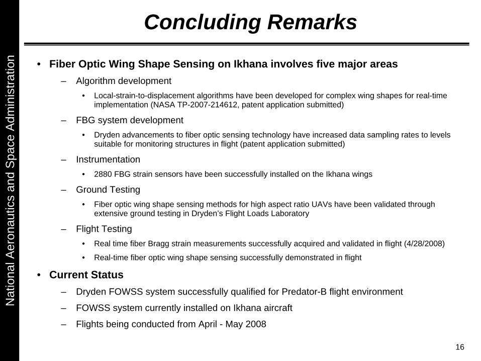
Concluding Remarks
• Fiber Optic Wing Shape Sensing on Ikhana involves five major areas– Algorithm development
• Local-strain-to-displacement algorithms have been developed for complex wing shapes for real-time implementation (NASA TP-2007-214612, patent application submitted)
– FBG system development • Dryden advancements to fiber optic sensing technology have increased data sampling rates to levels
suitable for monitoring structures in flight (patent application submitted)
– Instrumentation• 2880 FBG strain sensors have been successfully installed on the Ikhana wings
– Ground Testing• Fiber optic wing shape sensing methods for high aspect ratio UAVs have been validated through
extensive ground testing in Dryden’s Flight Loads Laboratory
– Flight Testing• Real time fiber Bragg strain measurements successfully acquired and validated in flight (4/28/2008)
• Real-time fiber optic wing shape sensing successfully demonstrated in flight
• Current Status – Dryden FOWSS system successfully qualified for Predator-B flight environment
– FOWSS system currently installed on Ikhana aircraft
– Flights being conducted from April - May 2008

17
Nat
iona
l Aer
onau
tics
and
Spa
ce A
dmin
istra
tion
Backup Slides

18
Nat
iona
l Aer
onau
tics
and
Spa
ce A
dmin
istra
tion
Dryden Fiber Optic System
• Current ground system specifications– Fiber count 4
– Max. fiber length 40 ft
– Max sensing length 20 ft
– Max. sensors / fiber 480
– Total sensors per system 1920
– Min. grating spacing 0.5 in
– Sample rate 2 fibers @ 50 sps 4 fibers @ 24 sps
– Interface Gigabit Ethernet
– Power 120 VAC
– Weight 12 lbs
– Size 9 x 5 x 11 in


![Flight Data Tools Applied to Engine Health Monitoring · Flight Data Tools Applied to Engine Health Monitoring ... GE90-115B[6] ... RPM Rotations Per Minute](https://img.dokumen.tips/doc/110x75/5b1e4d3c7f8b9ae6418b653c/flight-data-tools-applied-to-engine-health-monitoring-flight-data-tools-applied.jpg)