Embed Size (px)
Citation preview
Real-time holographic phase organization technique toobtain customized contouring of diffuse surfaces
Pramod K. Rastogi and Leopold Pflug
We report on the development of a holographic technique which allows one to obtain real time holographicfringes that reveal the whole field contour map of an arbitrary shaped object. The method enables one togenerate sensitivities compatible with the relief variations of objects of broadly varying depths. This isachieved by supplying enough 3-D modulation capacity to the system to develop the desired sensitivity. Theintersection planes can be pivoted to provide for an oblique slicing of the model. We describe the basic opticalconfiguration and discuss the system parameters. Experimental results are presented to illustrate theeffectiveness of the method. Key words: Holography, interferometry, real time, contouring, variablesensitivity.
1. IntroductionHolographic interferometry encompasses a group of
nondestructive techniques that can provide informa-tion on relief variations of an object surface.1-6 Apractical way to display this information consists ofobtaining contour maps showing the intersection ofthe object with a set of equidistant planes perpendicu-lar to the line of sight.
While using his now well-known sandwich hologra-phy Abramson3 showed that it was possible to obtaincontour maps by first tilting a plane-parallel glassplate in the illumination arm of the interferometerduring recording and then rotating the sandwich holo-gram during reconstruction. On the other hand, Yon-emura5 presented a method in which demodulationwas obtained by translation of the holographic plate ina double exposure experiment. In both cases the stan-dard planes have variable orientations.
Although ingenious in conception, these methodshave important drawbacks. The weak point is in thetype of demodulation procedure chosen and as a resultthe interference fringes tend to lose their visibilityrapidly. Yonemura reported that in the Fresnel ho-lography set up employed by him it was impossible toobtain intersection planes normal to the direction ofobservation. To make matters worse, arising at low
The authors are with Swiss Federal Institute of Technology, Lab-oratory of Stress Analysis, CH-1015 Lausanne, Switzerland.
Received 12 December 1989.0003-6935/91/131603-08$05.00/0.C) 1991 Optical Society of America.
sensitivities these difficulties impose a serious limita-tion on the measurable range of these methods.
The aim of this paper is to work out an effectivestrategy to obtain contour maps of a 3-D diffuse object.The strategy is implemented in three steps. First, weproduce a set of interference fringes modulating the 3-D variations of the object surface. These fringes arecreated by rotating the object surface around an axislying in its own plane.7 The second step naturallyconcerns itself with the demodulation of these fringesto extract a reconstructed object image with contourlines superposed on it. Each of these lines shouldrepresent the locus of all points which are equidistantfrom a fixed plane perpendicular to the line of sight.However, the sensitivity developed by the method inthis case is low. The third step is thus devoted torendering the method much more effective in contourmeasurement by providing it the means of varying itssensitivity in a wide range.
The real time nature of the method enables one togenerate sensitivities compatible with the relief varia-tions of objects of broadly varying depths. The fringesare of optimal quality and are displayed in real time ona TV screen.
II. PrincipleThe scheme of the experimental arrangement is
shown in Fig. 1. The object is illuminated by means ofa collimated beam making an angle 0 with respect tothe z-axis. The wavefront z scattered by the object isrecorded on the holographic plate. The plate after itsusual processing is repositioned in its original position.The wavefront ' emerging from the object is nowobserved in real time through the hologram.
1 May 1991 / Vol. 30, No. 13 / APPLIED OPTICS 1603
t
L
t AT,
HY'
x
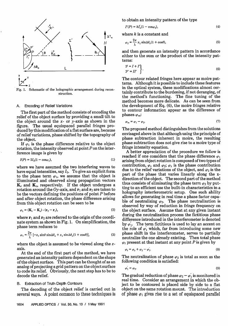
ZzFig. 1. Schematic of the holographic arrangement during recon-
struction.
A. Encoding of Relief Variations
The first part of the method consists of encoding therelief of the object surface by providing a small tilt tothe object around the x- or y-axis as shown in thefigure. The usual equispaced parallel fringes pro-duced by this modification of a flat surface are, becauseof relief variations, phase shifted by the topography ofthe object.
If s is the phase difference relative to the objectrotation, the intensity observed at point P on the inter-ference image is given by
I(P) = 21(1 - cos's,), (1)
where we have assumed the two interfering waves tohave equal intensities, say Io. To give an explicit formto the phase term spl, we assume that the object isilluminated and observed along propagation vectorsKe and K, respectively. If the object undergoes arotation around the Oy-axis, and r1 and r2 are taken tobe the vectors defining the positions of point P beforeand after object rotation, the phase difference arisingfrom this object rotation can be seen to be
(p = (Ke - Ko) (r2 - rl), (2)
where ri and r2 are referred to the origin of the coordi-nate system as shown in Fig. 1. On simplification, thephase term reduces to
s01 = A [-zl sinO sinAO0 + xl sinA0,(1 + cosO)], (3)
where the object is assumed to be viewed along the z-axis.
At the end of the first part of the method, we havegenerated an intensity pattern dependent on the shapeof the object surface. This part can be thought of as ananalog of projecting a grid pattern on the object surfaceto code its relief. Obviously, the next step has to be todecode the relief.
B. Extraction of Truth Depth ContoursThe decoding of the object relief is carried out in
several ways. A point common to these techniques is
to obtain an intensity pattern of the type
I'(P) = kl1,(l - COS 2), (4)
where k is a constant and2w
'P2 = 1 sinAO0 (1 + cosO), (5)
and then generate an intensity pattern in accordanceeither to the sum or the product of the intensity pat-terns:
5 = I + I'
9' IF 1 (6)
The contour related fringes here appear as moire pat-terns. Although it is possible to include these featuresin the optical system, these modifications almost cer-tainly contribute to the burdening, if not deranging, ofthe method's functioning. The fine tuning of themethod becomes more delicate. As can be seen fromthe development of Eq. (6), the moire fringes relativeto contour information appear as the difference ofphases S°m
'Pm = PI - (P2- (7)
The proposed method distinguishes from the solutionsenvisaged above in that although using the principle ofphase subtraction inherent in moire, the resultingphase subtraction does not give rise to a moire type offringe intensity equation.
A better appreciation of the procedure we follow isreached if one considers that the phase difference plarising from object rotation is composed of two types ofcontribution, sor and so2; Spz is the phase contributiondue to the relief variations of the object, and s02 is thepart of the phase that varies linearly along the x-direction of the object. The second part of the methodthus consists of eliminating the phase term so2 by put-ting to an efficient use the built-in characteristics in aholography interferometric setup. One such abilityallows for generating in real time a phase factor capa-ble of neutralizing So2. The phase neutralization isobserved by way of reduction in fringe frequency onthe object surface. Assume that at any given instantduring the neutralization process the fictitious phasedifference introduced in the interferometer is denotedby sol. The term fictitious is used to lay an accent onthe role of soi which, far from introducing some newphase shift in the interferometer, serves to partiallyneutralize the one already existing. Then total phasesot present at that instant at any point P is given by
't = (P, + 'P2 -'P- (8)
The neutralization of phase so2 is total as soon as thefollowing condition is satisfied:
= V2- (9)
The gradual reduction of phase so2 - soi is monitored inreal time. Consider an arrangement in which the ob-ject to be contoured is placed side by side to a flatobject on the same rotation mount. The introductionof phase (Pi gives rise to a set of equispaced parallel
1604 APPLIED OPTICS / Vol. 30, No. 13 / 1 May 1991

fringes on the flat object. This fringe pattern corre-sponds to the (P2 term. The phase term soi is subse-quently introduced to neutralize the phase factor *°2-
This manipulation results in a gradual reduction offringe frequency on the flat object with the progressiveintroduction of sol. The zero fringe condition impliesthe fulfillment of the equality shown in Eq. (9), and weobtain
Table 1. Maximum Values of Senstivity Az (Am) Generated by theMethod
\fx
0 1(deg) 1 fringe/mm 1.5 fringe/mm
30 3732 248840 2748 183250 2145 1430
(10)
The resulting fringe system corresonds to a contourmapping of the object surface. These fringes, unlikemoire, are not impressed on a carrier pattern. Yet theinformation carried by these fringes is obtained muchin the same way as that in the case of a moire, i.e., byphase subtraction. The phase of the observed fringesystem is given by
at =°m = 4°1 - (11)
The intensity pattern as shown in Eq. (1) is obtainedcorresonding to a phase change introduced on the livewavefront originating from the object surface. Look-ing at the reconstructed wavefront, let us assume that aphase difference (P2 is introduced on the reconstructedwavefront. Then Eq. (1) modifies to
I(P) = 2I [l- cos( 1 - 92)]. (12)
The information relative to (Pm is apparently trans-ported by the type of fringe system usual to holograph-ic interferometry.
The generation of the neutralizing phase corre-sponding to phase term so1 could be obtained in severalways. One possible way is to change the angle ofillumination of the reference beam slightly. If thereference beam is assumed to be collimated and lie inthe xoz plane, the appropriate phase shift (p1 is ob-tained by tilting the reference beam around the Oy-axis. The phase introduced on the reconstructed waveis given by
2ir(1 = A7 X sinAOr cSOr, (13)
where AOr is the small tilt provided to the referencebeam and 0r is the angle which the reference beammakes with the normal to the holographic plate.
For this phase modification not to lead to a delocal-ization of the fringe system from the object surface, thehologram must be translated along the x-direction byan amount given by
ATx = L cOSOr sinAOr, (14)
where L is the distance between the plate and object.The display of optimum contrast fringes on the objectsurface is a sufficient condition for the fulfillment ofthe condition specified in Eq. (14).
The neutralization of phase *°2 could be consideredto be complete as soon as the condition sol = S02 is
satisfied. The fringes modulating the object surfaceare contour planes intersecting the object in a directionperpendicular to the line of sight. The contour sensi-
tivity per fringe issuing from an increment of the dif-ference in phase fot equal to 2 is given by
(15)sinO sinAO0
The method, however, suffers from an importantdrawback-low sensitivity. Table I shows sensitiv-ities theoretically attainable by the method for threedifferent angles of illumination and two sets of fringefrequencies fx which arise as a direct consequence ofthe contribution of the portion of phase *02 in (pl. Thefrequencies of 1 and 1.5 fringe/mm are chosen on thehigher side of the frequency usually used in holograph-ic interferometry. Table I shows that the sensitivitiesgenerated by the method are still low. The third partof this study is devoted to the augmentation of themethod's potential by enhancing its sensitivity range.
C. Sensitivity EnhancementThe inability of the method to reach higher sensitiv-
ity levels is caused by the relief encoding part of themethod. The method is blocked by its limited capaci-ty to receive phase terms. The amount of phase intro-duced to generate a relief modulated fringe pattern islimited by the number of fringes that could be ob-served in relatively good conditions on the object sur-face. This fringe pattern in itself is made up of twocomponents contributed by the (p, and (P2 terms. Crip-pled by its undercapacity, the method is further ham-pered by the smaller proportion of the soz than S02 termin phase spl. This implies that in usual working condi-tions, 530 2 0 2 22°, the spatial frequency of fringes inthe x-direction is about two to five times higher thanthat in the z-direction.
This part of the method starts with Eq. (12) whichdescribes the presence of an interference contour pat-tern with contour interval given by Eq. (15). Since thecontribution of s02 in the original encoding pattern hasbeen completely erased from the displayed interfer-ence image, the interferometer is, as at the beginning ofthe experiment, once again receptive to the introduc-tion of more phases. The next step thus consists ofinjecting more phase terms of type spl, in the interfer-ometer. This modification regenerates a grid patternmodulating the object according to its shape but wherethe presence of the soz term now stands reinforcedcompared with that obtained at the end of the firstpart of the method. Let us call the additional phase sointroduced as Ao11. This phase increment is itselfcomposed of contributions coming from relief, Iand linear, A1021, phase variations, respectively.
1 May 1991 / Vol. 30, No. 13 / APPLIED OPTICS 1605
'Pt = z-

The phase difference A*021 is compensated by intro-ducing a phase shift A4o°l similar to o' in the interfer-ometer. A suitable manipulation of reference tiltgives rise to the formation of a fictitious grid patternwhich gradually eats into the contribution of A/021-When
(16)
the contribution of phase component A/021 to the fringesystem present on the object is totally canceled, andthe new equation for intensity becomes
I(P) = 2I[1 - cos(zp + A(zl)].
1000.
800'
s 600
.5
'W 400C)
200-
(17)
This expression represents the equation of a set ofcontour planes which are separated by
Az = XsinO sin(A0O + AO&)
where Al0 is the angle of rotation provided to theobject to inject phase shift A/pl1 in the interferometer.
The contour related fringe system has an optimumcontrast if the condition given by
AT. 1 = L cosO sinAOri (19)
is satisfied, whereAOr = AOr + AOri 1AT. = AT+AT (20)
AO', and AT' , being the increments of rotation andtranslation provided to the reference beam and thehologram plate, respectively.
This approach thus provides the method with thepotential to generate enhanced sensitivity contourmapping. Equation (18) shows an increase in sensitiv-ity over that obtained in Eq. (15).
Let us now assume that the procedure outlined forsensitivity enhancement is repeated several timesover. At the end of the nth step the phase situationpresent in the interferometer is expressed as
'Pin = 'Pz + ASPzl + A\Pz2 + * * * + A'Pzn, (21)
where Alozi denotes the out-of-plane phase incrementintroduced in the interferometer during the ith step.The resulting interferogram will have an optimumcontrast if
AT.n = L COSOr sinAOn, (22)
with ATn given by the sum of successive increments
ATxn =AT. +ATl+AT 2 +---+ A7§\n- (23)
Equation (21) represents the phase equation of a set ofcontour planes intersecting the object along the line ofsight. The distance between two successive planes isgiven by
Az = X(24)sinO sinA0on
where At~on is the total angle by which the object hasbeen rotated.
We have thus shown that a wide choice of contour
0 = 30-
0 = 50°
10 20 30 40 50 60 iofx (fringes/mm)
Fig. 2. Plots showing the variation of the amount of fringe frequen-cy generated vs sensitivity developed in the interferometer for two
different values of 0.
sensitivity is made available by implementing thephase strategy devised in this paper. An attractivefeature of the method is that it allows for adjusting itssensitivity to the object shape by relatively simplemeans.
The amplitude of phase movements that take placein the interferometer is made clearer by the plotsshown in Fig. 2. These plots are drawn for two valuesof illumination angles. Each curve gives the value ofcontour sensitivity, S, which is obtainable by themethod corresponding to a particular value of f. Ex-pressed in other words, only at this particular value offA, would the method develop in itself the capacitynecessary to deliver the Si contour sensitivity. Thisimplies that a fringe frequency f, of -75 fringes/mmwould automatically be generated if one wished toprovide the capacity to obtain a contour interval of 50Atm. The object is assumed to be illuminated at 300 tothe z-axis. A corresponding neutralizing phase mustthen be developed to deliver the contouring pattern asper specifications. Finally, a phase control allows oneto keep the fringe pattern corresponding to (pz near theobject surface. Without this control, the fringe visibil-ity plunges to zero long before the method can comeout of its low sensitivity range. That the method hasthe capacity to handle such large phase movements in acontrolled manner demonstrates the high performancelevels it can attain.
The problem of transverse speckle shifts in the ob-ject plane can be overcome by working in an imageplane configuration. In this way the image of theobject surface is formed on a photographic platethrough a lens with an aperture which governs thespeckle size in the image plane. The undesirabletransverse speckle shifts are completely eliminatedonly for those object points with corresponding imagepoints in the plane of the photographic plate. Thephase introduced on the reconstructed wave is similarto Eq. (13). In general the fringes are localized close tothe surface that is being contoured.
1606 APPLIED OPTICS / Vol. 30, No. 13 / 1 May 1991
11 .
A*°11 =` As211
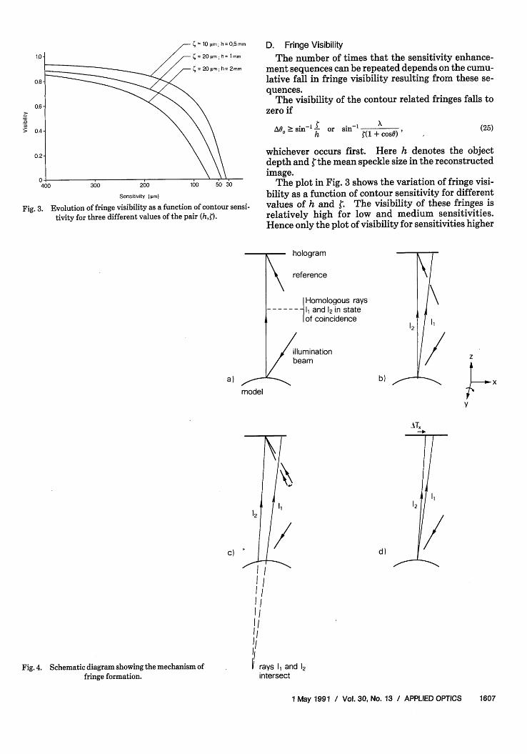
D. Fringe Visibility
The number of times that the sensitivity enhance-ment sequences can be repeated depends on the cumu-lative fall in fringe visibility resulting from these se-quences.
The visibility of the contour related fringes falls tozero if
AO5 2 sin-, - or sin-1 +h ~ (1 +coso) '
(25)
Sensitivity (ur)
Fig. 3. Evolution of fringe visibility as a function of contour sensi-tivity for three different values of the pair (h,¢).
a)modmodel
whichever occurs first. Here h denotes the objectdepth and the mean speckle size in the reconstructedimage.
The plot in Fig. 3 shows the variation of fringe visi-bility as a function of contour sensitivity for differentvalues of h and . The visibility of these fringes isrelatively high for low and medium sensitivities.Hence only the plot of visibility for sensitivities higher
7 hologram
reference
Homologous rays-__-_ I, and 12 in state
I of coincidence
illuminationbeam
12
b)
z
x
y
1212
c) d)
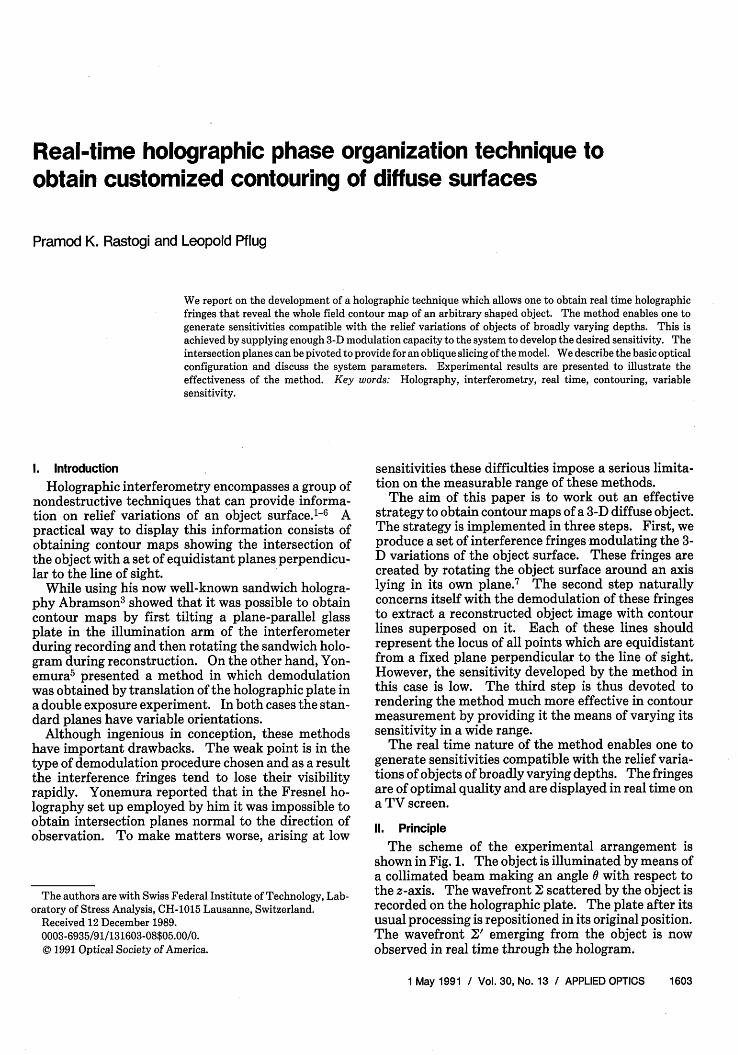
Fig. 4. Schematic diagram showing the mechanism offringe formation.
I II-IIIII
2 rays and 12intersect
1 May 1991 / Vol. 30, No. 13 / APPLIED OPTICS 1607
1,
than 400 Am is shown. Curves correspond to the varia-tion of fringe visibilities on contour planes, parallel to{O,xyl and situated 1, 2, and 0.5 mm away from it. Theobject is illuminated with an argon-ion laser emitting awavelength of 5145 A. The mean speckle size in thereconstructed image is assumed to be 20 Am for h = 1mm and 2 mm, and 10 mm for h = 0.5 mm. An impor-tant implication is deduced from these curves: thesmaller the speckle size, the smaller is the smoothlyvarying relief variations (small h) addressed by thetechnique.
E. Fringe FormationThe mechanism of fringe formation is shown sche-
matically in Fig. 4. A hologram of the object underconsideration is recorded and repositioned in its origi-nal position. The propagation of a pair of homologousrays8-10 (11,12) arising from a pointP on the reconstruct-ed and real object is shown in Fig. 4(a). The rotationof the object [Fig. 4(b)] around Oy gives rise to anangular shift of ray 11. The corresponding phase dif-ference induced in the interferometer is given by Eq.(3).
Ray 12 is shifted angularly by providing an appropri-ate tilt to the reference beam as shown in Fig. 4(c).The aim of this manipulation is to compensate thecontribution of the 2 term. A consequence of this isthat the point of intersection of the homologous raysmoves away from the object surface. The fringe sys-tem is no longer localized on the object surface. Arapid decrease in fringe visibility occurs as the fringesystem gradually fades away from the reconstructedobject image. The aperture of the observation systemhas to be shut down considerably to visualize thesefringes.
This situation can be avoided by providing an ade-quate translation to the holographic plate. The goal ofthis translation is to keep the point of intersection ofhomologous rays 1 and 12 on the object surface. Thevisibility of the fringe system is thus maintained at itsoptimum value.
The reinvigoration of fringe visibility leaves themethod ample room to improve its performance. Arepetition of the procedure shown in Figs. 4(b) and (c)once again creates a fringe system relative to contour-ing but with an improved sensitivity. On the otherhand, a lateral translation of the holographic plate[Fig. 4(d)] automatically adjusts the visibility of thedisplayed fringe system to its optimum value.
This procedure can be repeated several times toobtain a contour map tailored to the relief of the objectunder consideration. Besides allowing for displayinginterference contour maps of good quality, the revital-ization of the fringe visibility at the end of each cycle, b
c -- d, provides a considerable boost to the methodin its quest to improve its performance.
11. ExperimentsAn experimental system is installed to demonstrate
the feasibility of the proposed method. A collimatedbeam from an argon-ion laser is made to strike the
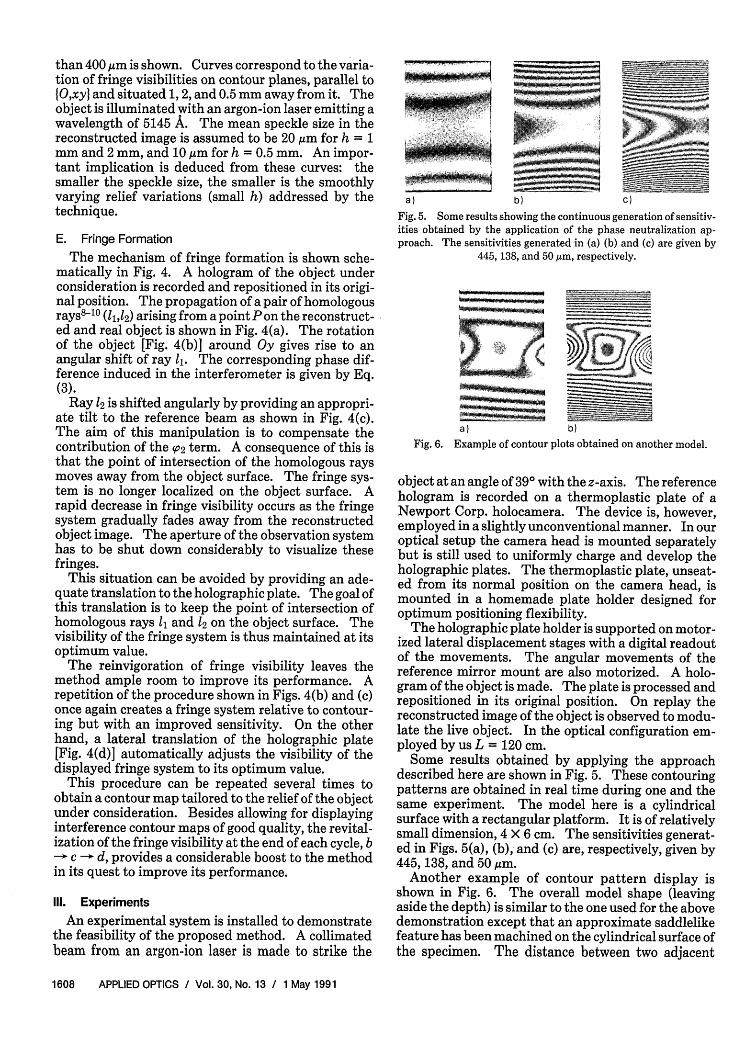
a) b) C)
Fig. 5. Some results showing the continuous generation of sensitiv-ities obtained by the application of the phase neutralization ap-proach. The sensitivities generated in (a) (b) and (c) are given by
445, 138, and 50 ,m, respectively.
a)
. .
Ab)
Fig. 6. Example of contour plots obtained on another model.
object at an angle of 390 with the z-axis. The referencehologram is recorded on a thermoplastic plate of aNewport Corp. holocamera. The device is, however,employed in a slightly unconventional manner. In ouroptical setup the camera head is mounted separatelybut is still used to uniformly charge and develop theholographic plates. The thermoplastic plate, unseat-ed from its normal position on the camera head, ismounted in a homemade plate holder designed foroptimum positioning flexibility.
The holographic plate holder is supported on motor-ized lateral displacement stages with a digital readoutof the movements. The angular movements of thereference mirror mount are also motorized. A holo-gram of the object is made. The plate is processed andrepositioned in its original position. On replay thereconstructed image of the object is observed to modu-late the live object. In the optical configuration em-ployed by us L = 120 cm.
Some results obtained by applying the approachdescribed here are shown in Fig. 5. These contouringpatterns are obtained in real time during one and thesame experiment. The model here is a cylindricalsurface with a rectangular platform. It is of relativelysmall dimension, 4 X 6 cm. The sensitivities generat-ed in Figs. 5(a), (b), and (c) are, respectively, given by445,138, and 50 um.
Another example of contour pattern display isshown in Fig. 6. The overall model shape (leavingaside the depth) is similar to the one used for the abovedemonstration except that an approximate saddlelikefeature has been machined on the cylindrical surface ofthe specimen. The distance between two adjacent
1608 APPLIED OPTICS / Vol. 30, No. 13 / 1 May 1991
P "MM"M!"'Mr,"�

a) b)
a)
b)
c)Fig. 7. Another example showing the possibility of the method tovary its sensitivity in a continuous manner and in real time. Thesensitivities achieved in (a), (b), and (c) are given by 1231, 410, and216 jm, respectively. These contourgrams are photographed from a
video monitor.
contouring planes in the patterns displayed in Figs.6(a) and (b) are, respectively, given by 1059 and 321,gm. If the fringes in Fig. 5 are not straight, it is morebecause of faulty machining of the specimen than theinfluence of field angles. This is further proved by theexample shown in Fig. 6 where by using the same
Fig. 8. Contour plane pivoted around the (a) Ox- and (b) Oy-axes toprovide for an oblique slicing of the model.
configuration as that in Fig. 5 the fringes are almoststraight.
The contour sensitivity is adjusted in real time bylooking at the interference image displayed on the TVscreen. Figure 7 shows an example of fringe patternsphotographed from a video monitor. The sensitivitiesdeveloped in Figs. 7(a), (b), and (c) are, respectively,given by 1231,410, and 216 ,tm. The model examinedis 4.3 cm in diameter. Figure 8 illustrates how themethod can pivot in real time the orientation of thecontour planes around the (a) Ox- and (b) Oy-axes.The smaller sides of the model are parallel to the Ox-axis.
IV. Method's AccomplishmentsThere are two ways to look at the accomplishments
of a method. One is to assess the end features offeredwith respect to their novelty, flexibility, and simplic-ity. The other way is to appreciate the mechanismsand interactions involved in the method's functioning.The first way allows the method to cover an unusuallybroad tuning range of contour sensitivity in real time.The monitoring of phase neutralization is also provid-ed in real time. The method is totally noncontact andoffers flexibility, rapidity, and simplicity of use. Theintersection planes can be pivoted to provide for anoblique slicing of the model.
The second way incorporates a phase matching solu-tion in which an internal phase adjustment (in contrastto an external phase adjustment which results in amoire) in the interferometer allows for obtaining afringe system sensitive to the topographic variations ofthe object surface. The phase matching is obtained bya subtle interaction of phases on the live and the recon-structed wavefronts. These wavefronts are addressedso as to maintain the presence of the fringe system inthe vicinity of the object surface. Broad tuning ofcontour sensitivity is obtained in a continuous andcontrolled way by successive introduction of phases inthe interferometer and their selective neutralization.More than anything else, the development of this ap-proach could be looked upon both as a test and tributeto the extreme versatility inherent in the real timereconstruction of wavefronts.
This research was supported by the Swiss NationalFoundation.
1 May 1991 / Vol. 30, No. 13 / APPLIED OPTICS 1609
References1. B. P. Hildebrand and K. A. Haines, "Multiple-Wavelength and
Multiple-Source Holography Applied to Contour Generation,"J. Opt. Soc. Am. 57, 155-162 (1967).
2. J. S. Zelenka and J. R. Varner, "Multiple-Index HolographicContouring," Appl. Opt. 8, 1431-1434 (1969).
3. N. Abramson, "Sandwich Hologram Interferometry. 3: Con-touring," Appl. Opt. 15, 200-205 (1976).
4. J. R. Varner, "Holographic Contouring Methods," in Handbookof Optical Holography, H. J. Caulfield, Ed. (Academic, NewYork, 1979), pp. 595-600.
5. M. Yonemura, "Holographic Contour Generation by SpatialFrequency Modulation," Appl. Opt. 21, 3652-3658 (1982).
6. R. Thalmann and R. Dandliker, "Holographic Contouring UsingElectronic Phase Measurement," Opt. Eng. 24, 930-935 (1985).
7. J. Tsujiuchi, N. Takeya, and K. Matsuda, "Measure de la d6for-mation d'un objet par interferom6trie holographique," Opt.Acta 16, 709-722 (1969).
8. C. Froehly, J. Monneret, J. Pasteur, and J. C. Vienot, "Etude desfaibles deplacements d'objets opaques et de la distortion opti-que dans les lasers a solide par interferometrie holographique,"Opt. Acta 16, 343-362 (1969).
9. S. Walles, "On the Concept of Homologous Rays in HolographicInterfeometry of Diffusely Reflecting Surfaces," Opt. Acta 17,899-913 (1970).
10. J. Monneret, "Etude theorique et expbrimentale des phbno-menes observables en interferom6trie holographique, interpre-tation des interf6rogrammes et applications a la metrologie desmicrod6placements," D.Sc. Thesis, U. Franche-Comt6, France(1973).
1610 APPLIED OPTICS / Vol. 30, No. 13 / 1 May 1991