Embed Size (px)
DESCRIPTION
Eye state recognition is one of the main stages of many image processing systems such as driver drowsiness detection system and closed-eye photo correction. Driver drowsiness is one of the main causes in the road accidents around the world. In these circumstances, a fast and accurate driver drowsiness detection system can prevent these accidents. Here, a fast algorithm for determining the state of an eye, based on the difference between iris/pupil color and white area of the eye is proposed. In the proposed method, vertical projection is used to determine the eye state. This method is suitable for hardware implementation to be used in a fast and online drowsiness detection system. The proposed method, along with other needed preprocessing stages, is implemented on Field Programmable Gate Array chips. The results show that the proposed low-complex algorithm has sufficient speed and accuracy, to be used in real-world conditions.
Citation preview

MAJOR PROJECT REPORT
On
REAL TIME EYE STATE RECOGNITION SYSTEM
WITH ZERO TRAINING OVERHEAD
Submitted by
KAVYA MANOHARAN (13120046) LEO ALEXANDER (13120049)
NAICINY C B (13120062) RAGINI (13120067) RESHMA C (13120074)
in partial fulfillment of requirement for the award of the degree
of
BACHELOR OF TECHNOLOGY
in
ELECTRONICS AND COMMUNICATION
DIVISION OF ELECTRONICS ENGINEERING
SCHOOL OF ENGINEERING

COCHIN UNIVERSITY OF SCIENCE AND TECHNOLOGY
KOCHI-682022
APRIL 2015
EC,SOE,CUSAT, 2011 Admission 2

EC,SOE,CUSAT, 2011 Admission 3

DIVISION OF ELECTRONICS ENGINEERING
SCHOOL OF ENGINEERING
COCHIN UNIVERSITY OF SCIENCE AND TECHNOLOGY
KOCHI-682022, KERALA, INDIA
Date: 20 April 2015
CERTIFICATE
Certified that the major project report entitled REAL TIME EYE STATE
RECOGNITION SYSTEM WITH ZERO TRAINING OVERHEAD is a bonafide
record of work done by KAVYA MANOHARAN, LEO ALEXANDER,
NAICINY C B, RAGINI and RESHMA C towards the partial fulfillment for the
award of the degree of B.Tech in Electronics and Communication of Cochin University of
Science and Technology, Kochi-682022.
Co-ordinators Head of the Division Dr. Binu Paul Dr. Binu Paul Dr. S. Mridula
EC,SOE,CUSAT, 2011 Admission 4

EC,SOE,CUSAT, 2011 Admission 5

ACKNOWLEDGEMENT
We express our sincere thanks to Dr. Binu Paul, Head of the Division of
Electronics Engineering, for her kind cooperation, encouragement and help.
We express our gratitude to our Co-ordinators Dr. Binu Paul and Dr. S Mridula
, Associate Professors, Division of Electronics Engineering for the expert guidance and
advice in presenting the Major Project.
We also take this opportunity to express a deep sense of gratitude to
Mr. Salih Muhammed in coordinating our activities and also for helping us throughout this
project.
Lastly, we thank almighty, our parents, brothers, sisters and friends for their
constant encouragement without which this project would not be possible.
KAVYA MANOHARAN (13120046)LEO ALEXANDER (13120049)
NAICINY C B (13120062)RAGINI (13120067)
RESHMA C (13120074)
EC,SOE,CUSAT, 2011 Admission 6

EC,SOE,CUSAT, 2011 Admission 7

ABSTRACT
Eye state recognition is one of the main stages of many image processing systems
such as driver drowsiness detection system and closed-eye photo correction. Driver
drowsiness is one of the main causes in the road accidents around the world. In these
circumstances, a fast and accurate driver drowsiness detection system can prevent these
accidents. Here, a fast algorithm for determining the state of an eye, based on the difference
between iris/pupil color and white area of the eye is proposed. In the proposed method,
vertical projection is used to determine the eye state. This method is suitable for hardware
implementation to be used in a fast and online drowsiness detection system. The proposed
method, along with other needed preprocessing stages, is implemented on Field
Programmable Gate Array chips. The results show that the proposed low-complex
algorithm has sufficient speed and accuracy, to be used in real-world conditions.
EC,SOE,CUSAT, 2011 Admission 8

EC,SOE,CUSAT, 2011 Admission 9

CONTENTS
1 Introduction 15
2 Real Time Eye State Recognition 172.1 Flow Chart 17
3 MATLAB 21
3.1 Introduction To MATLAB 21
3.1.1 MATLAB – Matrix Laboratory 21
3.1.2 Graphical Representation Of Data 21
3.1.3 Tools For Plotting 21
3.1.4 Flow Control 22
3.2 Image Processing Using MATLAB 23
3.3 Implementation In MATLAB 23
3.4 MATLAB Program 27
3.5 Simulation results 31
4 Hardware Implementation Design 35
5 Xilinx 43
5.1 Introduction to Xilinx 43
6 XILINX IMPLEMENTATION 47
6.1 Writing an image to a RAM 47
6.2 Image Ram 47
6.3 Adder Unit 47
6.4 PV RAM 48
6.5 PV RAM control circuit 48
6.6 Smoothening Unit and Control circuitry 50
6.7 MAXIMA / MINIMA SEARCHING UNIT 53
6.8 Control Circuit Of Max/Min Searching Unit 55
6.9 Condition Checking Unit 56
6.10 Control Circuit Of Condition Checking Unit 60
7 Conclusion 63
References 65
Appendix 67
Index 69
EC,SOE,CUSAT, 2011 Admission 10

EC,SOE,CUSAT, 2011 Admission 11

LIST OF FIGURES
Figure No. Description Page No.
Figure 1.1 Overall system for hardware implementation of an eye state recognition
16
Figure 2.1 Flowchart of drowsiness detection system 17Figure 2.2 (a) image of an Open eye (b) original Vertical
projection of the open eye (c) Smoothed and ZPPV of the open eye
19
Figure 2.3 (a) image of a closed eye (b) original Vertical projection of the closed eye (c) Smoothed
and ZPPV of the closed eye
20
Figure 3.1 The image of eye taken 30Figure 3.2 The graphs obtained 30Figure 3.3 The command window output 31Figure 3.4 (a) Working open eyes (b) Not working 32
Figure 3.5 (a) Working closed eyes (b) Not working 33Figure 4.1 (a) PV_RAM and its ports (b) control circuit
to obtained36
Figure 4.2 (a) Smoothing unit (b) control circuit of smoothing unit
38
Figure 4.3 (a) max/min searching unit (b) control circuit 39
Figure 4.4 Condition checking unit (a) type and location
checking (b) threshold checking (c) control
circuit of condition checking unit.
41
Figure 5.1 Simulink button 43Figure 5.2 Simulink and MATLAB 44Figure 5.3 (a) System generator token (b) Gateway in
block (c) gateway out block45
Figure 6.1 Writing an image to a RAM 47Figure 6.2 Image RAM 47Figure 6.3 Adder unit 47Figure 6.4 PV RAM 48Figure 6.5 PV RAM control circuit 48Figure 6.6 Output from PV RAM control circuit 49Figure 6.7 Phases of smoothening filter 50Figure 6.8 Smoothing unit 51Figure 6.9 Output from smoothing unit 52Figure 6.10 Smoothening control circuitary 52Figure 6.11 Output from Smoothening control circuitary 53
EC,SOE,CUSAT, 2011 Admission 12

Figure 6.12 Max/Min searching unit 54Figure 6.13 Register bank of Max/Min searching unit 54Figure 6.14 Output of Max/Min searching unit 55Figure 6.15 Control circuit of max/min searching unit 55Figure 6.16 Output of control circuit of max/min
searching unit56
Figure 6.17 Type and location checking block of condition checking unit
57
Figure 6.18 Output of type and location checking 58Figure 6.19 Threshold checking unit of condition
checking unit
59
Figure 6.20 Output of threshold checking unit of
condition checking unit
59
Figure 6.21 Circuit for the condition checking unit 60Figure 6.22 Output of control circuit for the condition
checking unit.
61
Figure A.1 Overall system for eye state recognition in xilinx
67
EC,SOE,CUSAT, 2011 Admission 13

LIST OF TABLES
Table No. Description Page No.
Table 3.1 Results of simulation in MATLAB
31
EC,SOE,CUSAT, 2011 Admission 14

EC,SOE,CUSAT, 2011 Admission 15

CHAPTER-1
Introduction
All over the world and every day, driver’s fatigue and drowsiness have caused many
car accidents. In fact, drowsiness is the case of about 20% of all car accidents in the world.
With the increasing popularity of automobiles, the traffic accidents have occurred
frequently, some of which are caused by fatigue driving, especially easily happen
standalone. The traffic accidents will be largely decreased if finding a judging rule to
determine whether drivers stay awake or not, and make a warning to the drivers when they
begin to fall asleep, so it is meaningful to research fatigue detection algorithm which is also
a key technology in smart vehicles driving. As a result, an electronic device to control the
driver’s awareness is needed. This device should monitor and detect the driver’s drowsiness
online and activate an alarm system immediately. In recent years, many researches on these
systems have been done and their results are reported .One of these methods is to monitor
the movement of the vehicle to detect drowsiness of the driver [6]. This method depends
very much to the type of vehicle and the condition of road. Another method is to process
the electrocardiogram (ECG) signals of driver [7]. In this system, some ECG probes are
needed to be connected to the driver, which are disturbing the driver. There are other
methods based on processing of the image of driver’s face and eye. Some of methods in
this category are to process the image of driver and to monitor his/her eye blinking.
In this report, a new algorithm to recognize the state of an eye, without constraints
of the previous methods, is proposed. This algorithm has less sensitivity to the light
conditions than other algorithms, with no need to a training phase. In order to verify the
correctness of the proposed algorithm, a computer simulation is developed. The results
show a fast performance and acceptable accuracy for the proposed train less eye state
recognition algorithm.
Here, grey level values of image of an eye is processed. Column wise sum of these
values are calculated and smoothened. Local maximas and minimas are found out and
specified conditions are checked. Status of the eye is found out from these conditions.
EC,SOE,CUSAT, 2011 Admission 16

Figure 1 shows overall system for hardware implementation of an eye state
recognition system. Image is stored in Image_ RAM and column wise sum of gray level
values is stored in PV_RAM. Adder1 helps in summation of the pixel values. Smoothening
unit does the smoothening process on the sum obtained. Local maxima and minima ,their
values and location are found in Max/Min searching unit. These values are used to find out
the state of eye using some conditions. Control circuit controls the whole operation. Eye
state is determined from the condition checking unit.
Figure 1.1 Overall system for hardware implementation of an eye state recognition
EC,SOE,CUSAT, 2011 Admission 17

CHAPTER-2
Real Time Eye State Recognition
2.1 Flow Chart
Figure 2.1 Flowchart of drowsiness detection system
In a driver drowsiness detection system based on image processing, first the
location of the face in the image is determined. Then, place of eyes are determined and
finally the image of an eye is processed to recognize the state of the eye. Proposed
algorithm recognizes the state of eyes to determine the driver drowsiness. The proposed
algorithm is as follows: First the gray level image of an eye is captured. Then, the vertical
projection of this image is obtained, by adding the gray level of pixels in each column. For
an m × n image the vertical projection vector, PV, is calculated using below equation.
PV(j) = for j = 1 to PVlen
EC,SOE,CUSAT, 2011 Admission 18

where i is the row number, j is the column number, and PVlen = n is the size of this
projection vector. For example, the original vertical projection of an image of an eye shown
in Figure 2.2(a) is depicted in Figure 2.2(b). The vertical projection vector needs to be
smoothened. To obtain a smooth vector, we use an averaging filter. The size of this
averaging filter, AFlen, is considered to be the floor of PVlen/7
AFlen = floor (PVlen/7)
As shown in Figure 2.2(a), the image of an open human eye has three different
areas, pupil/iris in the middle and two white parts in the left and right sides. However, in
the image of a closed eye, these areas are not discriminated. The effect of this observation
in the projection vector is the basis of our proposed algorithm to determine the state of the
eye. As shown in Figure 2.2(b), the projection vector of an eye in the open state has three
areas. The projection vector of the pupil and iris area has less gray values than two other
white areas. As a result, the projection vector has a local minimum in its middle, belongs to
pupil area, and two local maximums, belong to two white parts of the eye. The method
which searches for these local minimum and maximums in the projection vector is as
follows. First, we add AFlen/2 zeros to left and right sides of projection vector, to generate
the zero padded projection vector (ZPPV), with a length of ZPlen = PVlen + AFlen. If,
atleast one group in the ZPPV of the image satisfies the both following conditions then the
eye is open, otherwise it is closed.
Condition-1: The ratio of difference between Ysmax and Ymin to Ysmax is greater than a
threshold value, θ,
θ
Condition-2: The minimum that satisfies condition-1 is located almost in the middle of
ZPPV. That is, location of this minimum, Xmin is between 0.4ZPlen to 0.6ZPlen.
0.4ZPlen < X min < 0.6ZPlen
The ratio stated in condition-1 is based on the difference between the color of the
pupil (black) and the white area of an eye. This difference varies when the state of an eye is
changing from an open state to a closed state. That is, when an open eye is going to be
closed it passes different steps. Condition-1 verifies that an eye is open when this ratio is
greater than a threshold value.
EC,SOE,CUSAT, 2011 Admission 19

In the other hand, in the relaxed and open eye, such as driving situation, the pupil
almost in the center of eye, Condition-2 checked this condition to validate the openness of
the eye.
As an example, considering the image of an open eye, as shown in Figure 2.2(a).
Figure 2.2(b) is its projection vector and Figure 2.2(c) shows the smoothed and ZPPV of
this image. Based on our experiments the threshold of Condition-1 is considered to be θ =
0.05. Figure 2.2(c) is satisfied both conditions of an open eye, therefore it belongs to an
open eye.
Figure 2.2 (a) image of an Open eye (b) original Vertical projection of the open eye (c) Smoothed and ZPPV of the open eye
EC,SOE,CUSAT, 2011 Admission 20

(c)
Figure 2.3 (a) image of a closed eye (b) original Vertical projection of the closed eye (c) Smoothed and
ZPPV of the closed eye
EC,SOE,CUSAT, 2011 Admission 21

CHAPTER-3
MATLAB
3.1 Introduction To MATLAB
3.1.1 MATLAB – Matrix Laboratry
Initially developed by a lecturer in 1970’s to help students learn linear algebra.
It was later marketed and further developed under MathWorks Inc. (founded in 1984) – www.mathworks.com
MATLAB is a software package which can be used to perform analysis and solve mathematical and engineering problems.
It has excellent programming features and graphics capability – easy to learn and flexible.
Available in many operating systems – Windows, Macintosh, Unix, DOS
It has several toolboxes to solve specific problems.
3.1.2 Graphical Representation Of Data
Graphs are shown in a figure window. Several figure windows can be displayed simultaneously, but only one is active. All graphing commands are applied to the active figure. figure(n) - activate figure number n or create a new figure indexed by n.
3.1.3 Tools For Plotting
plot - produces a piecewise linear graph between its data values.
plot(y) -plots the values in vector y versus their index.
plot(x,y) -plots the values in vector y versus x.
stem -natural way of plotting sequences
stem(y) -Data sequence y is plotted as stems from the x axis terminated with circles for the data values.
stem(x,y) -plots the data sequence y at the values specified in x.
The plot and stem functions can take a large number of arguments.
The line type and color can easily be changed.
EC,SOE,CUSAT, 2011 Admission 22

xlabel('string') - Labels the x-axis with string.
ylabel('string') - Labels the y-axis with string.
title('string') - Gives the plot the title string
3.1.4 Flow Control
if The if statement evaluates a logical expression and executes a group of statements when the expression is true. If Statement Syntax:
if (Condition_1)MATLAB Commands;
elseif (Condition_2)MATLAB Commands;
elseif (Condition_3)MATLAB Commands;
elseMATLAB Commands;
End
for The for loop repeats a group of statements a fixed, predetermined number of times. A matching end delineates the statementsFor loop syntax:for i=Index_Array
MATLAB Commands;end
while Repeats a group of statements an indefinite number of times under control of a logical condition. A matching end delineates the statements. While Loop Syntax while (condition)
MATLAB Commands;end
switch case EC,SOE,CUSAT, 2011 Admission 23

The switch statement executes groups of statements based on the value of a variable or expression. The keywords case and otherwise delineate the groups.
3.2 Image Processing Using MATLAB
IMREAD()
The imread() command will read an image into a matrix.
IMSHOW()
To show our image, we the imshow() or imagesc() command. The imshow() command
shows an image in standard 8-bit format, like it would appear in a web browser.
The imagesc() command displays the image on scaled axes with the min value as black and
the max value as white.
IMWRITE()
To save your new image, use the imwrite() command
RGB2GRAY()
To convert RGB values to Gray level values.
3.3 Implementation In MATLAB
The approach to design a real time system to detect or recognize the eye state can
be implemented and tested by using matlab. The algorithm can be programmed and the
result can be verified using various images of eyes demonstrating different eyes states.
These images of eyes are obtained from a database- (CALTECH FRONTAL DATABASE)
and some of these images are capture by digital / mobile cameras.
ALGORITHM:-
1. Let us consider an image (taken from the database).
2. The image is first read and converted into a matrix. MAT2GRAY scale
transformation is done subsequently.
EC,SOE,CUSAT, 2011 Admission 24

I=imread(‘image name’);
B=mat2gray;
3. Pixels corresponding to each column is obtained and all the pixel values in a column
is added. Thus a row vector P is obtained. This is the projection vector.
P=sum(b);
4. Next an averaging filter is obtained.
Aflen=floor(No of columns/7); { No of columns= projection vector length}
5. Zeros are padded on both side of the projection vector.
6. Smoothening process starts. By using suitable weighting scheme the projection
vector is smoothened and smoothened data is obtained.
AF=ones(1,aflen);for j=1:z-1 if(j<aflen) o=0; for f=1:j o=o+1*zpv(1,f) end; AF(1,j)=o/aflen; elseif (j>=aflen)&(j<=z) pp=(j-aflen)+1; y=0; for f=pp:j y=y+1*zpv(1,f); end; AF(1,j)=y/aflen; end; AF
end;
7. Next the maxima and minima are searched for in the smoothened projection vector.
8. Each element in the array of smoothened projection vector is compared with the
preceding element.
9. A nine bit shift register is initialized and if a maxima occurs then a ‘1’ is stored in it
EC,SOE,CUSAT, 2011 Admission 25

else a ‘0’ is stored in it.
10. If the shift register pattern is “000001111” then it is a maximum. If it is “111100000”
then it is a minimum. Else it is neither a maximum nor a minimum.
if AF(i)>=AF(i-1)% compare a=1; else a=0; end A(9)=A(8); A(8)=A(7); A(7)=A(6); A(6)=A(5);A(5)=A(4);A(4)=A(3);A(3)=A(2);A(2)=A(1);A(1)=a; % shif register if A==[0 0 0 0 0 1 1 1 1 ] %% for maxm disp ('maxm') typ(w)=1; val(w)=AF(1,i-4); ind(w)=i-4; w=w+1; elseif A==[1 1 1 1 1 0 0 0 0 ] %% for minm disp ('minm')
11. On finding a maximum or minimum, its type(max/min), index, value of smoothened
vector are stored in three different arrays( registers). These registers are initialized
before.
12. Now the condition is checked concurrently. If the bit pattern in type array (register) is
101 then we obtain a minimum and two maxima. We find smallest maximum Ysmax
apply the constrains-
a. (Ysmax-Ymin) > (.05* Ysmax)
b. 0.4ZPlen < X min < 0.6ZPlen (i.e xmin lies in middle of the image of eye).
typ(w)=0;
val(w)=AF(1,i-4);
ind(w)=i-4;
w=w+1; end
EC,SOE,CUSAT, 2011 Admission 26

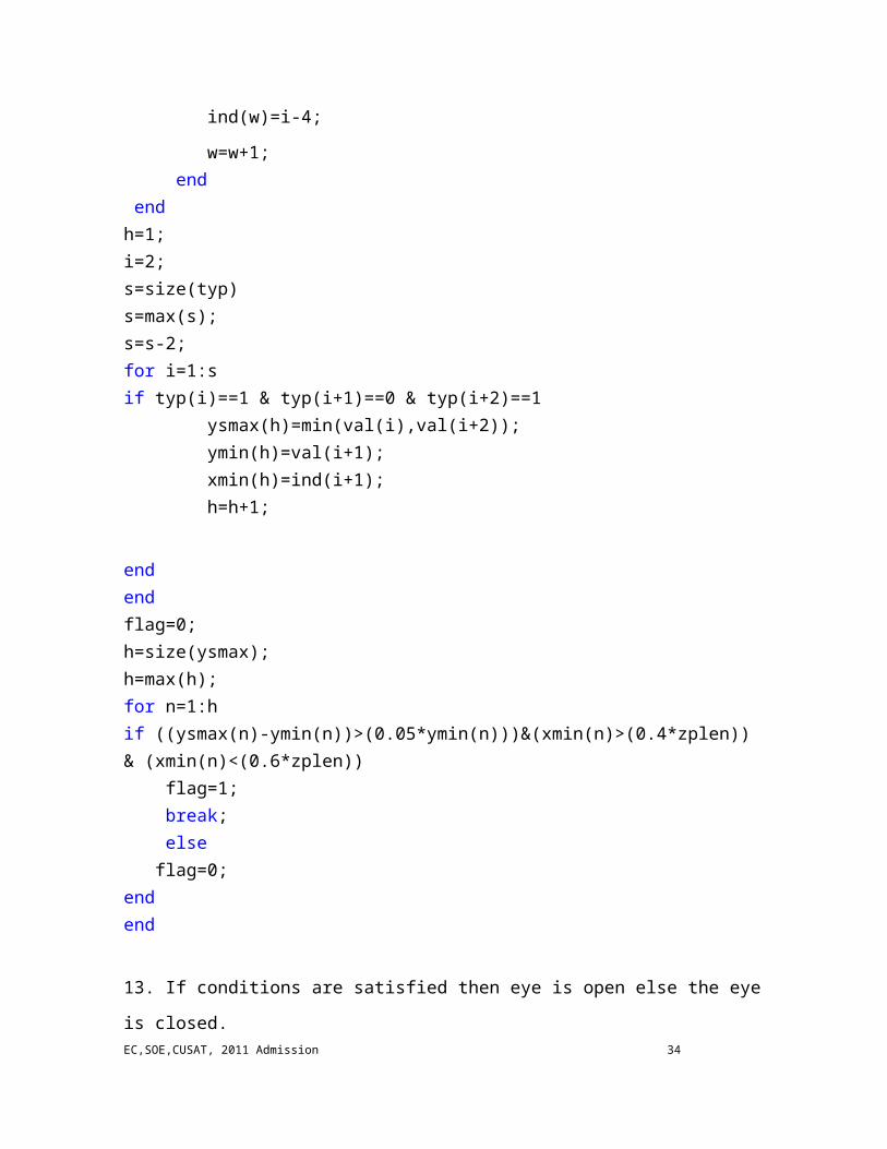
endh=1;i=2;s=size(typ)s=max(s);s=s-2;for i=1:sif typ(i)==1 & typ(i+1)==0 & typ(i+2)==1 ysmax(h)=min(val(i),val(i+2)); ymin(h)=val(i+1); xmin(h)=ind(i+1); h=h+1;
endendflag=0;h=size(ysmax);h=max(h);for n=1:hif ((ysmax(n)-ymin(n))>(0.05*ymin(n)))&(xmin(n)>(0.4*zplen)) & (xmin(n)<(0.6*zplen)) flag=1; break; else flag=0;endend
13. If conditions are satisfied then eye is open else the eye is closed.
if (flag==1) disp('Eye is open')elseif (flag==0) disp('Eye is Closed')end
14. Hence the algorithm is implemented using MATLAB codes.
3.4 MATLAB Program
% MATLAB program to detect the state of eye whether it is open or closed%
EC,SOE,CUSAT, 2011 Admission 27
% clear all the variablesclc;close all;clear all; % Reading the image and obtaining smoothened datai=imread('e_69.jpg');b=i(:,:,1); % red plane extractionb=mat2gray(b); % convert into grayscale image[m,n]=size(b);p=sum(b);% obtaining the projection vectoraflen=floor(n/7); % the filteraflenn=floor(aflen/2);aflenn % zero paddings
subplot(3,1,1);plot(p);xlabel('PVINDEX');ylabel('PV VALUE');title('original vertical projection of eye');% zero padded projection vectorzpv=padarray(p,[0 aflenn]);[x,z]=size(zpv)g=1:z;subplot(3,1,2);plot(zpv);xlabel('PVINDEX');ylabel('PV VALUE');title('zero padded vertical projection of eye');%smoothening processAF=ones(1,aflen);for j=1:z-1 %left side overlap if(j<aflen) o=0; for f=1:j o=o+1*zpv(1,f) end; AF(1,j)=o/aflen; elseif (j>=aflen)&(j<=z)% complete overlap
EC,SOE,CUSAT, 2011 Admission 28

pp=(j-aflen)+1; y=0; for f=pp:j y=y+1*zpv(1,f); end; AF(1,j)=y/aflen; end; AF end;%plotting smothened graph subplot(3,1,3); plot(AF) title('smoothened') figure; imshow(b) AF(1,j) A=zeros(1,9); w=1;[d, zplen]=size(AF)%initializationstyp(w)=0;val(w)=0;ind(w)=0;ysmax=0;ymin=0; for i=2:zplen-1 if AF(i)>=AF(i-1)% compare the elements of smoothened projection vectors a=1; else a=0; end A(9)=A(8); A(8)=A(7); A(7)=A(6); A(6)=A(5);A(5)=A(4);A(4)=A(3);A(3)=A(2);A(2)=A(1);A(1)=a; % shif register if A==[0 0 0 0 0 1 1 1 1 ] %% for maximum disp ('maxm') typ(w)=1; val(w)=AF(1,i-4);EC,SOE,CUSAT, 2011 Admission 29
ind(w)=i-4; w=w+1; elseif A==[1 1 1 1 1 0 0 0 0 ] %% for minimum disp ('minm') typ(w)=0; val(w)=AF(1,i-4); ind(w)=i-4; w=w+1; end end %initializations for type, index and location registersh=1;i=2;s=size(typ)s=max(s);s=s-2;%storing values in the registersfor i=1:sif typ(i)==1 & typ(i+1)==0 & typ(i+2)==1 ysmax(h)=min(val(i),val(i+2)); ymin(h)=val(i+1); xmin(h)=ind(i+1); h=h+1;endendflag=0;h=size(ysmax);h=max(h);%condition checking unitfor n=1:hif ((ysmax(n)-ymin(n))>(0.05*ymin(n)))&(xmin(n)>(0.4*zplen)) & (xmin(n)<(0.6*zplen)) flag=1; break; else flag=0;endend%displaying of resultif (flag==1) disp('Eye is open')elseif (flag==0)EC,SOE,CUSAT, 2011 Admission 30

disp('Eye is Closed')end
Figure 3.1 The image of eye taken
Figure 3.2 The graphs obtained
EC,SOE,CUSAT, 2011 Admission 31

Figure 3.3 The command window output
3.5 Simulation results
Number of corrects Number of Incorrect Accuracy (%)
Open eye 37 6 86.0Closed eye 29 5 85.3Total 66 11 85.7
Table 3.1 Results of simulation in MATLAB
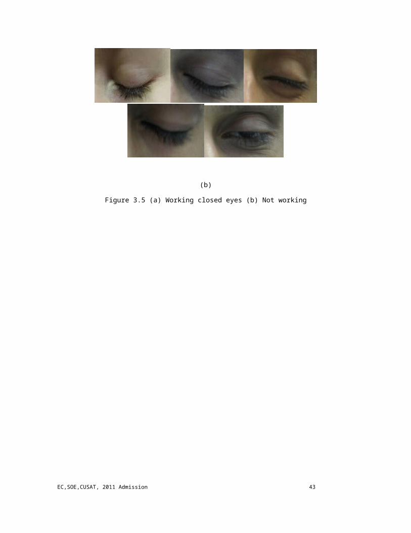
We tested 66 eye images both from Caltech frontal database and outside the database. Out of 43 open eyes, 37 images gave correct results. Also, from 34 images of closed eyes, 29 images gave output as closed. Results of this simulation gave an accuracy of 86% for open eyes and 85.3% for closed eyes. Overall accuracy obtained is 85.7%. Some of the tested eyes which are working and not working are added here:
EC,SOE,CUSAT, 2011 Admission 32

Open Eye
(a)
(b)
Figure 3.4 (a) Working open eyes (b) Not working
EC,SOE,CUSAT, 2011 Admission 33
Closed Eye
(a)
(b)
Figure 3.5 (a) Working closed eyes (b) Not working
EC,SOE,CUSAT, 2011 Admission 34

EC,SOE,CUSAT, 2011 Admission 35

CHAPTER-4
Hardware Implementation Design
In order to implement the proposed algorithm on a hardware platform, we
assume that the image of an eye is stored in a Random Access Memory (RAM). In this
implementation, we use a RAM with 136 × 82 bytes, called IMAGE_RAM, to store an
image. We also used a True dual port RAM, called PV_RAM, with 136 of 15-bit words, to
store the projection vector. Three other major units in the design are data smoothing unit,
local max/min search unit, and condition checking unit. These units are controlled through
a control circuit. Vertical projection vector is obtained in the first part of this system
containing IMAGE_RAM, PV_RAM, and Adder1. All elements of each column of the
image, IMAGE_RAM, are added together, by ADDER1, and the result is stored into
vertical projection vector, PV_RAM, through port B. The stored Data is read from
PV_RAM through port A. This data corresponds to a column of the eye image. The address
of IMAGE_RAM is generated through IMAGE_RAM_ADRESS register/counter, a ring
counter which counts from 0 to 11151. The address of PV_RAM is also generated by
PV_RAM_ADRESS1, a ring counter which counts from 0 to 135. When the projection
vector is completed, PV_C flag is set; and then smoothing unit starts its process.
(a)
EC,SOE,CUSAT, 2011 Admission 36

(b)
Figure 4.1 (a) PV_RAM and its ports (b) control circuit to obtained
For implementation of smoothing unit, we use the following procedure:
Since the length of the projection vector is 136, the length of smoothing filter is equal to
19 .The values of all tap weights of this smoothing filter, averaging filter, are considered to
be ‘1’. In the smoothing process, there are three distinguish phases. In the first phase,
smoothing filter has some overlap with data projection vector from the left. In the second
phase smoothing filter is completely overlapped with data projection vector. In the third
phase, smoothing filter has some overlap with the projection vector from the right.
EC,SOE,CUSAT, 2011 Admission 37

In smoothing procedure, we need to divide the summation of projection vector data which
are overlap with smoothing filter to the length of the smoothing filter, AFlen. To simplify
the hardware implementation of this procedure we approximate the AFlen with the nearest
number of 2k, less than AFlen. In the other word, if 2k <AFlen < 2k+1 then the denominator
consider to be 2k.
Dividing a number by 2k is a k-bit shift to the right. In our simulation, for example, since
AFlen = 19, we considered k = 4 and instead of division in averaging procedure, we shift
the result 4 bits to the right. Smoothing flag, SC_F, is set during smoothing procedure.
(a)
EC,SOE,CUSAT, 2011 Admission 38

(b)
Figure 4.2 (a) Smoothing unit (b) control circuit of smoothing unit
In Max/Min searching unit, the local maximum and minimum of
smoothed vector, generated through smoothing unit, are obtained. The input to this unit is
the arrays of smoothed vector which is generated at each step. In order to find the local
minimum and maximums of the smoothed projection vector, we used the following
method.
In this method, each element of smoothed vector, di, is compared to the previous element,
di-1. If di ≥ di-1 then a ‘1’ is shifted into a 9-bit shift register. This shift register always
contains the result of the last nine comparisons. If this shift register has a pattern equal to
“000001111” then it indicates a maximum in the smoothed vector. If this shift register has a
pattern equal to “111100000” then it indicate a minimum in the smoothed vector.
Otherwise, there is neither a minimum nor a maximum in this part of the vector. When a
maximum or minimum is found, its type (max/min), its location (the index of the vector),
and its value of the smoothed vector at this minimum or maximum, di-4, are stored. If a
maximum occurred then a ‘1’ is stored in the type register, otherwise, a ‘0’ is stored. The
index of the location is stored in the step counter. The value of the smoothed data of this
minimum or maximum, di-4 ,is obtained from R4 of the register bank.
EC,SOE,CUSAT, 2011 Admission 39

(a)
(b)
Figure 4.3 (a) max/min searching unit (b) control circuit
Last unit of this system is the condition checking unit. In this unit, conditions of maximums
and minimums are checked, concurrently. In each step of type checking, three successive
bits of type register is selected. If these three bits have a pattern of “101” then a minimum
EC,SOE,CUSAT, 2011 Admission 40

exist between two maximums. We called this minimum in this group as Ymin. The index of
this minimum in ZPPV is called Xmin. Also in each group one of the maximum is less than
the other which we called it Ysmax.
If Xmin is between (54, 81), then Condition-2 is satisfied.
Condition 2: 0.4ZPlen<Xmin<0.6ZPlen
Condition-1 can be checked as follows: First, we can rewrite Condition1:
Ysmax−Y min > θ × YsmaxWe set θ = 0.05; Substituting value of θ in above equation,
Ysmax−Y min > 0.05 × YsmaxWhere in binary mode we have,
Ysmax−Y min > (2-5 + 2-6) × YsmaxBoth sides of the equation are multiplied by 28, so the equation becomes,
28 × (Ysmax−Y min) > (23 + 22) × Ysmaxwhich is simpler and easier for implementation.
(a)
EC,SOE,CUSAT, 2011 Admission 41

(b)
(c)
Figure 4.4 Condition checking unit (a) type and location checking (b) threshold checking (c) control circuit
of condition checking unit.
This procedure is repeated for all frames and PV_RAM is cleared when
the process of one frame is completed. Therefore, data are overwritten on PV_RAM, when
IMAGE_RAM_ADDRESS points to the first column of IMAGE_RAM. Control circuit
controls the flow of data. When the first row of IMAGE_RAM is read then the inputs of the
EC,SOE,CUSAT, 2011 Admission 42
adder are connected to IMAGE_RAM and ‘0’. When the other rows of IMAGE_RAM are
read then the inputs of the adder are connected to IMAGE_RAM and output port A of
PV_RAM.
EC,SOE,CUSAT, 2011 Admission 43

CHAPTER-5
Xilinx
5.1 Introduction to Xilinx
Xilinx System Generator provides a set of Simulink blocks (models) for several
hardware operations that could be implemented on various Xilinx FPGAs. These blocks
can be used to simulate the functionality of the hardware system using Simulink
environment. The nature of most DSP applications requires Floating point format for data
representation. While this is easy to implement on several computer systems running high
level modelling software such as Simulink, it is more challenging in the hardware world
due to the complexity of the implementation of floating point arithmetic. These challenges
increase with portable DSP systems where more restricting constraints are applied to the
system design. For these reasons Xilinx System Generator uses fixed point format to
represent all numerical values in the system. System generator provides some blocks to
transform data provided from the software side of the simulation environment (in our case
it is Simulink) and the hardware side (System Generator blocks). This is an important
concept to understand during the design process using Xilinx System Generator. The
System Generator runs within the Simulink simulation environment which is part of
MATLAB mathematical package. To start Xilinx system generator, we need to open
MATLAB (versions 2011 onwards) and open simulink library. Type simulink at the
MATLAB command prompt or click the Simulink button in the MATLAB toolbar to open
the Simulink Library Browser.
Figure 5.1 Simulink button
Examine the available blocks in the Simulink Library Browser.The following elements, among others, should appear:
Simulink (sources and sinks)
EC,SOE,CUSAT, 2011 Admission 44

Xilinx Blockset
Xilinx Reference Blockset
Xilinx XtremeDSPKit
Figure 5.2 Simulink and matlab
The Simulink library browser shows a list of all the different Toolboxes installed within MATLAB.
Xilinx System Generator components will appear under three categories:
1. Xilinx Blockset
2. Xilinx Reference Blockset
3. Xilinx XtremeDSP Kit
The category Xilinx Blockset contains all the basic blocks used in various number of applications.
Create a new Simulink model by selecting File→New→Model.
EC,SOE,CUSAT, 2011 Admission 45

From the Simulink Library Browser, open the Xilinx Blockset Library to access the
blocks.We must use Xilinx Gateway In / Gateway Out blocks to define the FPGA
boundary and we must also place a Xilinx System Generator token in the design.
(a) (b) (c)
Figure 5.3 (a) system generator token (b) Gateway in block (c) gateway out block
Insert the required blocks from Xilinx blockset in the simulink library to create the
required model. To connect with blocks other than Xilinx blocks, we need to use gateway
in and gateway out. To take a signal from outside the Xilinx blockset we should use a
gateway in. And to take a signal outside Xilinx.
EC,SOE,CUSAT, 2011 Admission 46

EC,SOE,CUSAT, 2011 Admission 47

CHAPTER-6
XILINX IMPLEMENTATION
6.1 Writing an image to a RAM
Figure 6.1 Writing an image to a RAM
Image from file block reads an image from a file. We can use the File name
parameter to specify the image file we want to import into the model. Color space
conversion block can be used to convert color information to intensity values. Reshape unit
changes the dimensions of a vector or matrix input signal. Output dimensionality is set as a
1 dimensional array which is input to an unbuffer block that converts a frame to scalar
samples output at a higher rate. This is input to Single port RAM in our model that stores
the image pixel values in 1-D array to be used for processing.
6.2 Image Ram
Figure 6.2 Image ram
Its a single port ram that stores image. Size of image ram equals size of image. Port address
is used to select the required pixel value of the image.
6.3 Adder Unit
Figure 6.3 Adder unit
EC,SOE,CUSAT, 2011 Admission 48

It performs the required addition to generate projection vector. Its a simple adder that sums
the two inputs given to it.
6.4 PV RAM
Figure 6.4 PV Ram
Its a dual port RAM that stores data width upto 256 bits. The ports are functionally
identical and independent of each other. That is, it enable shared access to the single
memory space. Here, port a is set as read port and port b as write port. Projection vector
calculated is stored in PV RAM.
6.5 PV RAM control circuit
Figure 6.5 PV RAM control circuit
Functions of PV RAM control circuit are:
1. Generate image RAM address
2. Generate address of PV RAM
EC,SOE,CUSAT, 2011 Admission 49

3. To generate enable signal to the smoothening unit.
4. To provide input for adder
5. To provide PV RAM port b address.
6. To provide write enable signal for port b of PV RAM.
7. To generate address of port a of PV RAM
Functioning:
Address of PV RAM is generated using an up counter and a comparator that limits
the count to the length of projection vector.
Image RAM address is generated using another up counter and a comparator that
compares the count with the size of image and hence limit the count. When the image RAM
address generation is complete, a control signal projection vector flag (PVC_F) is set.
Figure 6.6 Output from PV ram control circuit
To get sum of entire elements in each column, we use a two input multiplexer
(mux1) that selects the stored sum per column from PV RAM output once the image RAM
address generation is complete for one row of pixel values of original image. Port b address
of PV RAM is generated using another two input multiplexer (mux) that inputs a delayed
PV RAM address until pvc_f is set and then takes input from s_address2 signal from
smoothening control unit. Write enable signal for port b of PV RAM is generated using a
EC,SOE,CUSAT, 2011 Admission 50

third multiplexer (mux3) which disables web after pvc_f is set. Port a address of PV RAM
is selected using another multiplexer (mux2) that inputs PV RAM address until pvc_f is set
and then inputs s_address1 during smoothening process to read port a values into
smoothening unit.
6.6 Smoothening Unit and Control circuitry
When the projection vector is completed, PV_C flag is set, and then smoothing unit
starts its process .For implementation of smoothing unit, we use the following procedure:-
Since the length of the projection vector is 136, the length of smoothing filter is equal to 19.
The values of all tap weights of this smoothing filter, averaging filter, are considered to be
‘1’. In the smoothing process, there are three distinguish phases. In the first phase,
smoothing filter has some overlap with data projection vector from the left. In the second
phase smoothing filter is completely overlapped with data projection vector. In the third
phase, smoothing filter has some overlap with the projection vector from the right.
Figure below shows these three phases.
Figure 6.7 Phases of smoothening filter
EC,SOE,CUSAT, 2011 Admission 51

In smoothing procedure, we need to divide the summation of projection vector data
which are overlap with smoothing filter to the length of the smoothing filter, AFlen. To
simplify the hardware implementation of this procedure we approximate the AFlen with the
nearest number of 2k, less than AFlen. In the other word, if 2k < AFlen < 2k+1 then the
denominator consider to be 2k. Dividing a number by 2k is a k-bit shift to the right. In our
simulation, for example, since AFlen = 19, we considered k = 4 and instead of division in
averaging procedure, we shift the result 4 bits to the right. Smoothing flag, SC_F, is set
during smoothing procedure.
Figure 6.8 Smoothing unit
EC,SOE,CUSAT, 2011 Admission 52

Figure 6.9 Output from smoothing unit
Figure 6.10 Smoothening control circuitry
EC,SOE,CUSAT, 2011 Admission 53

Figure 6.11 Output from Smoothening control circuitry
6.7 MAXIMA / MINIMA SEARCHING UNIT
In Max/Min searching unit, the local maximum and minimum of smoothed
vector, generated through smoothing unit, are obtained. The input to this unit is the arrays
of smoothed vector which is generated at each step. The 15-bit input from Smoothing unit
is input to the Max/Min searching unit. This input and its delayed version is compared. If
the current input is greater than the delayed one, a “1” is stored in the Max/Min register
which is a 9-bit serial in-parallel out shift register. If the above is not satisfied, a “0” will be
stored. This shift register always contains the result of the last nine comparisons. If this
shift register has a pattern equal to “000001111” then it indicates a maximum in the
smoothed vector. If this shift register has a pattern equal to “111100000” then it indicate a
minimum in the smoothed vector. When a maximum occurs, a “1” is stored to Type
Register through a MUX. When a minimum occurs, a “0” is stored to Type Register.
Otherwise, there is neither a minimum nor a maximum in this part of the vector. Output of
the comparators act as enable signal for Min/Max Register Bank, Step Counter Bank and
Type Register. The smoothed 15 bit data input is given as input to 10 registers (R0-R9)
connected serially. Data is shifted to right in each clock and value of register R4 is stored in
EC,SOE,CUSAT, 2011 Admission 54

Min/Max Register bank which is enabled only if condition in comparator 9 and 10 are
satisfied. Step counter bank stores the index of the location of the Min/Max value. Type
register is a 20-bit serial in parallel out shift register that stores whether the data is
minimum or maximum. The output of Min/Mux Registers bank is Max/Min, Step counters
bank is Location 2 and Type Register is a 20 bit.
Figure 6.12 Max/Min searching unit
Figure 6.13 Register bank of Max/Min searching unit
EC,SOE,CUSAT, 2011 Admission 55

Figure 6.14 Output of Max/Min searching unit
6.8 Control Circuit Of Max/Min Searching Unit
Figure 6.15 Control circuit of max/min searching unit
EC,SOE,CUSAT, 2011 Admission 56

Figure 6.16 Output of control circuit of max/min searching unit
Control circuit of Max/Min searching unit generates x-index value of smoothened
data. It contain 8-bit counter and a comparator that limits the count upto 153. The control
signal from the smoothening unit SC_F is ANDed with output of comp11 (a>b) that
enables the counter. X-index is generated by subtracting 4 from output of the count. The
output of Adder6 is Location_1.
6.9 Condition Checking Unit
Last unit of this system is the condition checking unit. In this unit, conditions of
maximums and minimums are checked, concurrently. The output from type register is
given as the input to three muxes that selects three adjacent inputs from type register with
the help of condition_address generated by control circuit of the condition checking unit.
Three successive condition addresses are given as the select input to the three MUXs. Three
successive bits have been selected as the output and these outputs are compared with the
pattern “101”. That is, the output of first MUX is compared with the first bit “1” then the
second mux output with “0” and the third mux output with “1”.
EC,SOE,CUSAT, 2011 Admission 57

On the other side, the condition-1 is checked. For this, each bit of location_2 is
taken as the Xmin and this value is compared with the threshold values using the
comparators.
Condition 1: 0.4 Z Plen < Xmin < 0.6 Z Plen
The ZPlen values have been calculated from the MATLAB program part that we
did and is found to be 153. The output from all the comparators are given to an AND gate
that checks if all the conditions are satisfied or not. If the conditions are satisfied ,then
output of AND gate will become 1. This output is given to D flipflop. The output Q of this
flipflop is taken as condition 1 and the qbar is fed into the AND operator. Thus this
condition checking will check only once and the output will remains zero other times.
Figure 6.17 Type and location checking block of condition checking unit
EC,SOE,CUSAT, 2011 Admission 58

Figure 6.18 Output of type and location checking
Concurrently, Condition-2 is checked.
Condition-2:
θ
As explained in chapter 4, the above condition can be simplified as follows:
28 × (Ysmax−Y min) > (23 + 22) × Ysmax
To implement this equation, the minimum or maximum value from the min/max
register bank of maxima/minima searching unit is fed to three multiplexers that selects
three adjacent values from the min/max register bank with the help of condition_address
generated by control circuit of condition checking unit. The outputs of first and third
multiplexers, that is two maximums are compared. The minimum of these is Ysmax.It is
stored in the Min/max register and the output of second multiplexer is directly stored in
Min register since it is corresponds to the minimum value. To calculate the left side of
above equation, the Ymin and Ysmax are subtracted and the result is shifted to left by 8-
bits using a shift register. Concurrently, Ysmax is shifted 2 and 3 bits to the left and they
are added to obtain right side of the equation. The comparator unit compares these two
sides to check the threshold condition. Then the result is ANDed with condition1 output.
Then the output is taken from the D flipflop .
EC,SOE,CUSAT, 2011 Admission 59

Figure 6.19 Threshold checking unit of condition checking unit
Figure 6.20 Output of threshold checking unit of condition checking unit
EC,SOE,CUSAT, 2011 Admission 60

6.10 Control Circuit Of Condition Checking Unit
Then comes the control circuit for the condition checking unit. It comprises of one
counter and two comparators. It is designed to count upto 17. The output from the counter
is the condition_address. This is given as select input to the first mux. To get select input
of second mux add a 1 to it, this is condition_address1. To get condition_address2 add 2 to
the condition_address and this is the select input of third mux. Then we can compare
adjacent 3 locations to check for required conditions.
Figure 6.21 Circuit for the condition checking unit
EC,SOE,CUSAT, 2011 Admission 61

Figure 6.22 Output of control circuit for the condition checking unit.
EC,SOE,CUSAT, 2011 Admission 62

CHAPTER-7EC,SOE,CUSAT, 2011 Admission 63
Conclusion
In this project, an algorithm to determine the state of an eye by using its image was
presented. In this algorithm, we used the fact that the pupil and iris are darker than white
part of the eye. We used the vertical projection to distinguish the state of the eye. The
proposed method performed well in different light and eye color conditions. The computer
simulation included 77 eyes in which 66 eyes gave desired output and hence the system
showed 85.7% accuracy. Hardware design and implementation in Xilinx were also
presented.
Applications include real time detection of eye state of a person driving a vehicle,
detection of other similar patterns based on gray scale values, security maintenance
purposes, control of interfaces like computer mouse by monitoring eye blink.
EC,SOE,CUSAT, 2011 Admission 64

EC,SOE,CUSAT, 2011 Admission 65

References
1. Mohammad Dehnavi and Mohammad Eshghi (2012), ‘Design and implementation
of a real time and train less eye state recognition system EURASIP Journal on
Advances in Signal Processing asp.eurasipjournals.com/content/pdf/1687-6180-
2012-30.pdf, pp. 1-12
2. Drowsy Driving. http://dimartinilaw.com/motor_vehicle_accidents/
car_accidents/drowsy_driving/. Accessed 2 May 2011
3. Newsinferno news site. http://www.newsinferno.com/accident/drowsydriving-
behind-1-in-6-fatal-traffic-accidents. Accessed 2 May 2011
4. Xilinx co, http://www.xilinx.com. Accessed 2 May 2011
5. Eye SBU database. http://faculties.sbu.ac.ir/~eshghi/sbu-database-9008/
one_eye.rar
6. P Boyraz, JHL Hansen (2008), ‘Active accident avoidance case study: integrating
drowsiness monitoring system with lateral control and speed regulation in passenger
vehicles’, in IEEE International Conference on Vehicular Electronics and Safety,
ICVES 2008 pp.293–298.
7. K Yun Seong, L Haet Bit, K Jung Soo, B Hyun Jae, R Myung Suk, P Kwang
Suk(2007), ECG, EOG detection from helmet based system, in 6th International
Special Topic Conference on Information Technology Applications in Biomedicine,
2007. ITAB 2007,pp.191–193.
EC,SOE,CUSAT, 2011 Admission 66

EC,SOE,CUSAT, 2011 Admission 67

APPENDIX
EC,SOE,CUSAT, 2011 Admission 68

EC,SOE,CUSAT, 2011 Admission 69

EC,SOE,CUSAT, 2011 Admission 70

Index
Averaging filter......................................................................................18,24
Caltech frontal database.........................................................................23,31
Color space conversion..........................................................................47
Condition checking unit.........................................................................39
Drowsiness.............................................................................................17
Dual port RAM......................................................................................35
FPGA....................................................................................................43
Gray level values..................................................................................17
Image RAM..........................................................................................35,41
Max/min searching unit........................................................................38
Pixel values...........................................................................................24
Projection vector..................................................................................17,24
PV_C Flag............................................................................................35,49
Register bank........................................................................................38
SC_F flag………………………………………………………………..37
Single port RAM...................................................................................47
Smoothing unit......................................................................................36,38
Smoothing filter..................................................................24,36
Smoothened projection vector..........................................38
Tap weights………………………………………………...36
Step counter………………………………………………………....…38,53
Threshold value……………………………………………………..…18
Type register…………………………………………………………...25
Vertical projection……………………………………………………..17
Xilinx blockset………………………………………………………….44
Gateway in............................................................................45
EC,SOE,CUSAT, 2011 Admission 71

Gateway out.........................................................................45
Simulink...............................................................................43
System generator…………………………………………...43
Zero padded projection vector…………………………………...40
EC,SOE,CUSAT, 2011 Admission 72


![5 Eye-Opening HR Stats: Why Employee Recognition Matters [INFOGRAPHIC]](https://img.dokumen.tips/doc/110x75/58e9488e1a28ab262c8b4dab/5-eye-opening-hr-stats-why-employee-recognition-matters-infographic.jpg)


