Embed Size (px)
Citation preview

Real-time CAD Model Matching for Mobile Manipulation and Grasping
Ulrich Klank, Dejan Pangercic, Radu Bogdan Rusu, Michael BeetzIntelligent Autonomous Systems, Technische Universitat Munchen,
Boltzmannstr. 3, Garching bei Munchen, 85748, Germany
Abstract— Humanoid robotic assistants need capable andcomprehensive perception systems that enable them to performcomplex manipulation and grasping tasks. This requires theidentification and recognition of supporting planes and objectsin the world, together with their precise 3D pose. In thispaper, we propose a 3D perception system architecture thatcan robustly fit CAD models in cluttered table setting scenesfor the purpose of grasping with a mobile manipulator. Ourapproach uses a powerful combination of two different cameratechnologies, Time-Of-Flight (TOF) and RGB, to robustlysegment the scene and extract object clusters. Using an a-prioridatabase of object models we then perform a CAD matchingin 2D camera images. We validate the proposed system in anumber of experiments, and compare the system’s performanceand reliability with similar initiatives.
I. INTRODUCTION
As personal mobile manipulation platforms come to age,they require perception systems that can recognize andtrack objects with real-time performance. These perceptionsystems should also include inference mechanisms for de-termining the most probable grasping points such that theobjects of interest can be manipulated using stable grasps.However, the current state of the art in 3D perception formanipulation architectures is represented by implementationswhich require substantial computational efforts to recognizeand reconstruct object models from sensed data, and generategood strategies for grasping them.
In this paper, we propose a 3D system architecture forperception that addresses the problem of precise object mod-eling and tracking for grasping applications. Our approachmakes use of databases of a-priori acquired object models,and identifies objects of interest and their 6D pose in thesensed data. The hardware setup consists of a combinationof stereo and Time-Of-Flight (TOF) cameras, as shown inFigure 1. The CAD object models are fit in 2D imageswith real-time performance, using constraints automaticallydetermined from the 3D point cloud data (PCD) obtainedusing the TOF camera.
Our 6D pose object recognition algorithms can handlearbitrarily complex shapes, without any assumptions aboutocclusions, distance to object, or object rotation with respectto the camera. The object models are correctly identifiedand matched in real-world scenes, independent of the typeof surface the objects are made of, and most importantly,without making use of any texture information. The latter isof extreme importance for objects present in household envi-ronments which are most often textureless. This constitutesan important advantage over other similar recently proposed
SwissRanger SwissRanger 4000 (TOF)4000 (TOF)
Stereo Stereo camerascameras
Fig. 1. The mobile manipulation platform used for the purpose ofthe experiments presented herein. The hardware setup consists of a B21mobile base with two 6-DOF PowerCube arms, stereo cameras and a TOFcamera mounted near the end effector. The right part of the figure presentsinterpretation results given by the perception system, from top to bottom: i) atextureless occluded white mug identified and localized; ii) 3D segmentationof object clusters on the table; iii) four distinct objects localized in a clutteredtable scene.
research initiatives [1], [2], which fail to work in the absenceof good texture-based features.
The system presented in this paper is based on our recentlyproposed work on matching approximated CAD models [7],[19], using extensions of the work presented in [16], [18].Here we continue our work by incorporating 3D range datainto the the existing camera based algorithms to improve theresults both in terms of speed and robustness.
Our application scenario can be described as follows.Given a surface representation of an object, either acquired inan a priori step, or extracted from a database of shape models,identify the object and its position in real-time in a scene, andprovide a suitable grasping pose for a mobile manipulator.The grasping points for a model are estimated offline usingOpenRAVE [4]. An example object models identified in acluttered scene can be seen in Figure 2.
The object models are used to identify the most probableedge occurrences in 2D images. While this can be performeddirectly in the entire image space, the search can leadto increased computational demands which might not besuitable for application with real time constraints. Another

Fig. 2. Four different objects matched in a cluttered table setting. Theprojection of the matched CAD models is displayed in green.
disadvantage of the brute-force search is that extreme cluttercould potentially interfere with the solutions found by thematching algorithm, and result in matches with a poorgeometric correspondence (i.e., objects flying in thin air).Our proposed extensions include the inference of supportingplanes (e.g., tables) from 3D depth data provided by aTOF camera, in order to generate consistent places whereobjects could be located, and region growing and clusteringmechanisms for the segmentation of individual objects intopotential Regions Of Interest in the image space. The noveltyof our approach is represented by the realization of a real-time integrated object identification system based on CADmodel matching for the purpose of grasp identification inmobile manipulation applications.
The software components necessary to perform the tasksdiscussed in this work are modular so they can be reusedindividually. Because of their modularity, they can be usedfor robots other than the system presented in this paper. Inparticular, we make use of the ROS open source initiative1
to build our distributed system.
II. RELATED WORK
The problem that we are trying to solve falls in the contextof perception for manipulation. We therefore split the relatedwork discussions into three distinct parts that correspondto the respective subjects covered in this paper, namely:i) similar mobile manipulation platforms with detection-localization-grasping capabilities, ii) object classification andlocalization in indoor environments based on depth data andiii) 2D camera images respectively.
The STAIR platform [10] uses a peripheral visual ob-ject detection system working with a steerable pan-tilt-zoom camera to obtain high-resolution images. The authorsdemonstrate grasping in a comprehensive “fetch a stapler”application, based on a large training set of labeled naturaland synthetic household objects [13].
1ROS (Robot Operating System - http://ros.sourceforge.net) is an OpenSource project to build a meta-operating system for mobile manipulationsystems.
The humanoid robot ARMAR-III is presented in [17],together with a perception system that can localize small andlarge-sized household objects. The system makes use of arecognition step using 2D-2D feature point correspondencesfrom Hough transforms and an iterative estimation of anaffine transformation, while the 6D pose estimation methodmakes use of a stereo triangulation algorithm.
A perception system for the PR2 (Personal Robot 2)manipulation platform is presented in [11]. The authors makeuse of a 2D laser tilted continuously on a pan-tilt unit, whichprovides a 3D point cloud map representing the surroundingworld in front of the robot. The perception system is capableof constructing dynamic collision maps used by a motionplanner to avoid obstacles while moving the robot arms, andcan recognize tables and object clusters supported by them.
A humanoid two-arm system built for studying dexterousmanipulation is presented in [9]. Its real-time perceptionsystem is based on a 3D-Modeller head that comprisesa laser-range scanner, a laser-stripe profiler, and a stereocamera sensor. Object pose hypotheses are obtained byapplying the invariant Haar measure of the Euclidean groupSE(3) on the data provided by the composite sensor, andthen fed to the manipulation system. The work of [12]discusses the extraction of planes in range data. A systemfor object recognition and segmentation in range data ispresented in [5].
The last step of our problem is to match many 3D objectsin 2D images. This problem was solved before and thereare many different methods, such as [6] for example, whichis based on generating many views of a 3D object. We areusing a state of the art 3D shape model matching technique,which is described in [16], [18]. This method matches 3D-CAD-models in an image by simulating the 2D appearancein a shape model generation phase. A range of positionrelative to the camera must be specified, which can only bedone if information about the scene is available. A similarapproach which makes use of line and circle segments, waspresented in [8]. Another approach that can recognize shapesvia geometric features was presented in [15].
III. SYSTEM ARCHITECTURE
The overall architecture of the proposed system is depictedin Figure 3. Our mobile manipulation platform (Figure 1)has a SwissRanger 4000 TOF camera mounted on one ofits end-effectors (6-DOF arm) and two RGB color camerasattached to a Pan-Tilt-Unit (PTU) on top of the robot body.The platform is controlled via several subsystems includingPlayer [3], and ROS.
The task executive is in charge of controlling the overallsystem operation and creates/starts separate threads based onthe current state of the system. In particular, the executivecontrols:• the way the detection and localization of objects is
performed;• the arm motion planning and grasping.The modules responsible for the detection and localization
of object models in camera images are outlined in the
3D PCD Processing Node3D PCD Processing NodeImage Processing NodeImage Processing NodeManipulationManipulation
Task executive (ROS)Task executive (ROS)
RGB cameraRGB camera TOF cameraTOF camera6-DOF arms6-DOF arms
3D CAD model-based3D CAD model-basedlocalizationlocalization
Object clustering & ROI Object clustering & ROI extractionextraction
Arm motionArm motionplanningplanning
GraspingGrasping
Clustering & plane fittingClustering & plane fitting
Normal estimation & filteringNormal estimation & filtering
Search space creationSearch space creation
Fu
nctio
nal L
ayerF
un
ction
al Layer
Hard
ware
Hard
ware
Fig. 3. The architecture of our system using the ROS paradigms. Theplanar estimation and cluster segmentation steps are performed by the 3DPCD processing node (right) whose output is fed into an image processingnode (middle) which performs the detection and localization of objects. Ourmotion planning and grasping is spawned as a separate system thread (left).
following sections.The Point Cloud Data acquired from the TOF camera is
processed in a ROS node which extracts horizontal planes(e.g. tables) and point clusters supported by them (e.g.,objects). Our algorithms are optimized and can process theincoming data and provide results at a frequency of over20Hz.
The resultant plane equation, its center point, and thecentroids of the estimated point clusters together with theirvolumetric extensions are then fed to the image processingnode via ROS’s service/messaging system. After a con-strained search space has been built and the objects aresuccessfully localized (see Sec. IV-B), the task executivestarts another process that plans and executes a motion planthat brings the end effector into a position where the objectcan be grasped.
IV. THE PERCEPTION SYSTEM
To be able to efficiently perform grasping, our roboticsystem must first be able to perceive the objects of interestin its surroundings, and it must do so accurately and rapidly.This perception component is fundamental to both detectionand localization of the objects. Our approach makes use ofCAD model matching techniques in camera images.
In order to be efficient, the localization of an object needsa restricted search space. This restriction is necessary toefficiently build up a search tree of possible projections thatallow a fast online search even for complex models. Therestriction of such a search space is not trivial and it cannotbe done in advance, due to the fact that the surrounding en-vironment might have changed since the last state. Thereforewe need a context aware method that generates such a searchspace on demand.
In the previous version of our system we used priors likethe size and orientation of supporting planes in a room.This required a precise localization of the robot, especiallywith respect to the orientation of the cameras towards thesupporting plane. Even if this plane is often given by thehardware setup, it might be disturbed by obstacles and ingeneral, an inaccurate localization.
In the work presented herein, we make use of a TOFcamera (see Figure 1) to estimate the best supporting planesin real-time, and thus improve the segmentation of object
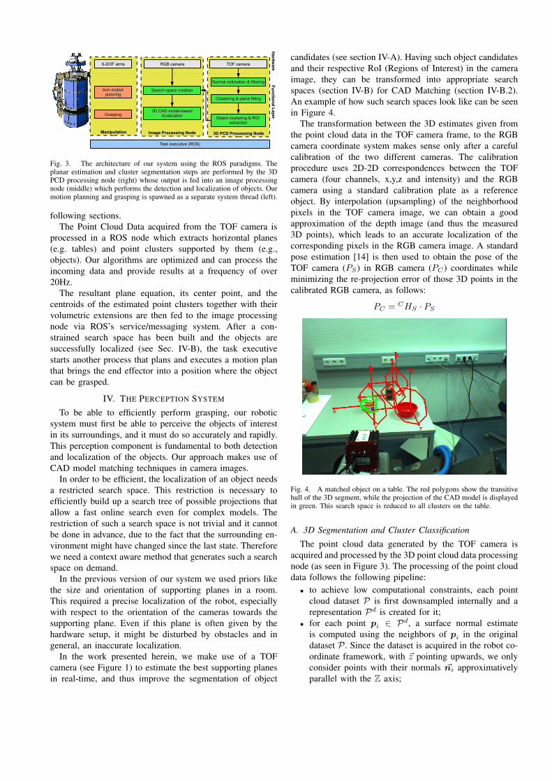
candidates (see section IV-A). Having such object candidatesand their respective RoI (Regions of Interest) in the cameraimage, they can be transformed into appropriate searchspaces (section IV-B) for CAD Matching (section IV-B.2).An example of how such search spaces look like can be seenin Figure 4.
The transformation between the 3D estimates given fromthe point cloud data in the TOF camera frame, to the RGBcamera coordinate system makes sense only after a carefulcalibration of the two different cameras. The calibrationprocedure uses 2D-2D correspondences between the TOFcamera (four channels, x,y,z and intensity) and the RGBcamera using a standard calibration plate as a referenceobject. By interpolation (upsampling) of the neighborhoodpixels in the TOF camera image, we can obtain a goodapproximation of the depth image (and thus the measured3D points), which leads to an accurate localization of thecorresponding pixels in the RGB camera image. A standardpose estimation [14] is then used to obtain the pose of theTOF camera (PS) in RGB camera (PC) coordinates whileminimizing the re-projection error of those 3D points in thecalibrated RGB camera, as follows:
PC = CHS · PS
Fig. 4. A matched object on a table. The red polygons show the transitivehull of the 3D segment, while the projection of the CAD model is displayedin green. This search space is reduced to all clusters on the table.
A. 3D Segmentation and Cluster Classification
The point cloud data generated by the TOF camera isacquired and processed by the 3D point cloud data processingnode (as seen in Figure 3). The processing of the point clouddata follows the following pipeline:• to achieve low computational constraints, each point
cloud dataset P is first downsampled internally and arepresentation Pd is created for it;
• for each point pi ∈ Pd, a surface normal estimateis computed using the neighbors of pi in the originaldataset P . Since the dataset is acquired in the robot co-ordinate framework, with ~z pointing upwards, we onlyconsider points with their normals ~ni approximativelyparallel with the Z axis;

• a clustering in normal space is performed in Pd, tosimplify and reduce the overall errors that might affectthe planar segmentation step;
• in each cluster, the best planar support candidate isestimated using a sample-consensus approach. Eachplan is weighted with respect to the camera viewpoint,and the model with the largest weight is selected asa table candidate. The weight is a simple measure ofthe number of inliers in the dataset, together with theestimated 2D area of the model;
• once the table equation is estimated, a search for all thepoint clusters supported by it is performed, by lookingwhether the projection of the points pi ∈ P falls insidethe bounds of the 2D table polygon.
Algorithm 1 outlines those steps in pseudo-code while avisualization is provided by Figure 5.
Algorithm 1 Find tables and objectsP = {p1 · · ·pn} // set of 3D pointsfor all pi ∈ P do
estimate (ni from Pk) // estimate surface normal from nearest neighborsif (α = 〈ni, Z〉 ≈ 0) // check if the normal is parallel to the Z axis thenPz ← pi // add pi to the Pz set
estimate (C = {P1z · · · P
nz },P
iz ⊂ Pz) // break Pz into clusters
for all ci ∈ C do// find the best plane fit using sample consensusestimate ({a, b, c,d},a · px
i + b · pyi + c · pz
i + d = 0,pi ∈ ci)estimate (amin, amax) // find the min/max bounds of the planar areaTM ← F (ci) // add the table parameters to the table mapfor all pi ∈ P do
if (axmin ≤ nx
i ≤ aymax, a
ymin ≤ ny
i ≤ aymax) // within bounds? then
Po ← pi // add pi to the Po set of cluster candidatesestimate (O = {P1
o · · · Pno },P
io ⊂ Po) // break Po into clusters
B. Search Space Calculation
Before propagating the point cloud data to the visualsystem we want to represent the search space in a compactform. Therefore, we describe the clustersO using their centerpoints and their maximal extensions along the xyz coordinateaxes. The extents are then converted to a 6 × 6 diagonalmatrix, representing the estimated uncertainty of the clusterposes.
The matrix representation can be efficiently propagatedthrough the different coordinate systems, to the final extentsin the camera based spherical and image coordinates whichwe use to set up the search space of the CAD matching step.In our experiments we did not encounter any drawbacks fromthis compression scheme, since we have to overestimate thevisual search space anyway because of the relatively largebaseline between the RGB and the TOF cameras.
1) 3D Points to Search Space: Given that we have a pointwith its orientation in a 3D space, we interpret this pointas an object to camera relation. To include such a point inthe RGB camera search space we have to add its projectioninto a Region of Interest (RoI) image and transform it intospherical coordinates. The latter enables modelling of theRGB camera image on a sphere with a radius r at a posedescribed by 3 angles, the longitude α, latitude β and cameraroll γ. Given an already defined search space with 〈αmin,αmax, βmin, βmax, γmin, γmax, rmin and rmax〉, we haveto adapt it as soon as the point falls outside the RoI. For eachpoint found nearby an already existing RoI, we extend the
respective region to include the point by modifying its outerdimensions. Figure 6 shows an example of the 3D clustersestimated using the methods presented in Section IV-A, hereback-projected into the RGB camera image.
Fig. 6. Backprojection examples of the 3D clusters estimated using themethods in Section IV-A into the RGB camera image.
2) CAD Matching: The CAD models of the objects thatwe want to localize are usually acquired as an a-priori stepusing precise laser sensors followed by a number of geo-metric processing steps (sometimes involving manual laborto clean the models), or can be alternatively downloadedfrom the Internet [7]. Most household objects available inthe internet databases can be found lying on supporting xy-planes in the 3D model coordinates. This is of course anassumption we do not rely completely upon, but we assumethat the majority of the models are aligned in such a way.Since we additionally also align all selected inlier modelsto each other, we obtain the major “upright” direction.Following this we can assume that given a supporting planewe only have to account for one of the three rotationaldegrees of freedom.
Shape matching approaches require significant preprocess-ing of the given 3D model, whose complexity is polynomi-ally increasing with the number of faces in the model andlinearly with the number of views that have to be generatedto get a complete search. The number of views in ourapplication depends mainly on the given search space in thespherical coordinates system. Thus the constrained regionsof interest reduce the search phase significantly.
To obtain fast results, we build a tree containing theprojection of the model in different resolutions (image pyra-mids), with all leafs similar to their parents but at a higherresolution. The similarity of a match is measured in the2D appearance of the projection. The information resultedfrom the segmentation step in the point cloud data givesa significant reduction in r, the distance to the camera,while α, β are only slightly affected by our search spacerestrictions, since we still search for the same classes ofpossible orientation on the table. If it is possible to reducethe RoI and the search range of γ, this would only affectthe calculation time in the search phase. A very roughapproximation of the estimated model calculation time isgiven as follows:
step ∼(max(xir, y
ir)
)rmin
tmodel ∼ Nvf step(αmax−αmin)(βmax−βmin)(rmax−rmin)
where xir and yir represent the resolution of the imageand Nv
f is the number of visible faces. Similarly, we can

(a) Raw PC data (b) Table plane estimation (c) Clusters of objects (d) Clusters of objects - close up
Fig. 5. From left to right: raw point cloud data acquired using the TOF camera, the identification of the table plane, and the segmentation of the pointssupported by the table into clusters of objects.
approximate the expected calculation time for the searchphase by:
tsearch ∼ step ∗ (γmax − γmin) ∗N1cand
where N1cand is the number of candidate matches on the
highest pyramid level, which corresponds directly with thesize of the regions of interest used.
V. DISCUSSIONS AND EXPERIMENTAL RESULTS
For the sake of completeness, we briefly review some ofthe previous results we obtained in [7] in order to introducethe new approach presented in this paper. In our previouswork we showed how to obtain CAD models from theGoogle 3D Warehouse and successfully match them againstsimple objects in table setting scenes. Once localized, andusing a set of preprocessed grasping points, our mobilemanipulation platform is capable of picking up the objectusing a stable grasp, as seen in Figure 12. However, themajor problems that we faced concern the missing robustnessagainst clutter and the high calculation time of the modelgeneration phase. The following sections demonstrate sig-nificant improvements in terms of computation speed anddetection robustness in cluttered scenes, using our newlyproposed system architecture.
A. Computational Efficiency
To demonstrate the computational advantages obtained byincorporating the 3D clustering information into the imagesearch space, we performed several tests for different objectslocated in various cluttered scenes. In each experiment,we recorded the calculation time necessary for the modelgeneration phase and the one for the search phase. Since thefour objects present a large variety in the number of facesthat their CAD models contain, the overall calculation timescan vary significantly.
The experiments include a comparison between the resultsobtained using the entire search space of the full table versusthe one automatically generated by the PCD processingnode. Figure 8 shows the resultant calculation times for themodel generation phase. As presented, the highest relativecalculation time gain is obtained when a number of faces inthe object is high as well. Additionally, the relative size ofthe cluster with respect to the initial search space influencesthe calculation time. The smaller the segmented clusters are,
Fig. 8. The gained speed up by using clusters instead of the full table(about 30000cm3). For a better overview of the effects of our approach,we divided the clusters into big (>= 750cm3) and small (< 750cm3)clusters. The bars show the calculation time taken for generating the modelfor the given search region for several objects with various number of faces.
Fig. 9. The gained speed up by using clusters instead of the full table(about 30000cm3). For a better overview of the effects of our approach,we divided the clusters into large (>= 750cm3) and small (< 750cm3)clusters. The bars show the calculation time taken for searching in thesearch region for an object.
the higher is the gain. This can be seen by comparing thecalculation times for large and small clusters. An exampleof a large cluster is an ice tea box, while a small cluster canbe caused by an appearance of the mug, as seen for example

Fig. 7. Successful fitting examples for different object models in cluttered scenes. From left to right: i) an ice tea box, ii) a mug, iii) two mugs, and iv) atea box are correctly localized in the camera image.
in Figure 10.The time needed for the clustering added up to ≈ 50ms
per frame and is omitted in Figures 8 and 9. The modelgeneration can be skipped for new search spaces if therewas another model generated before, that contains the currentsearch space completely. Figure 9 shows the calculationtimes for the search phase. Again, the graph compares thecalculation time with and without the segmentation. Thisexperiment included the assumption of the object standingupright on the table having an arbitrary orientation. Allmeasurements were done on a AMD Athlon(tm) 64 X2 DualCore Processor 3800+, which constitutes one of the two stockcomputers of our mobile manipulation platform.
B. Robustness through Search Space Segmentation
To show that this approach increases the robustness of thesystem we compared the search of several objects in morecomplex scenes.
Fig. 10. An example of a single model search in a cluttered scene, usingthe entire search space (left), and using several regions of interest fromthe 3D processing module (right). Notice that the multiple RoI approach isrobust against false positives, while in the full search space, the model ofthe mug is matched incorrectly.
Fig. 11. A mismatch example with a wrong distance in the full searchspace (left), solved by using the multiple RoI approach(right). The modelto be localized is represented by a mug.
An example is shown in Figure 10, where the robustnessof the localization framework was greatly improved by usingthe resultant 3D clusters from the point cloud data. Incontrast, the approach using a full search over the entirespace can return erroneous results, due to problems withfalse positive matches. This can be observed particularlyin scenes that contain similar or highly textured objects,
Tea IceTea Mug Plate AllSingle Object 0.5 1.0 1.0 0.75 0.88–with segmentation 0.75 1.0. 1.0 0.75 0.88Partial Occlusions 1.0 0.75 1.0 1.0 0.94–with segmentation 1.0 0.75 0.75 1.0 0.88Cluttered Scene 0.2 0.75 0.6 0.2 0.44–with segmentation 0.6 0.6 0.75 0.75 0.68Overall 0.54 0.66 0.76 0.75 0.72–with segmentation 0.76 0.84 0.84 0.83 0.82
TABLE ITHE RESULTS FOR TESTS ON 37 DIFFERENT SCENES, INCLUDING BOTH
APPROACHES: WITH AND WITHOUT SEGMENTATION. THE NUMBERS ARE
A RATIO OF GOOD DETECTED OBJECTS AGAINST PRESENT OBJECTS.
where we can easily hallucinate degenerated views of anobject. Here, by a degenerated view we represent situationswhere several projected 3D edges fall on the same 2Dline. A similar problem can be seen in Figure 11 whereanother object matches the projection of a mug model. Theseproblems are tackled with the segmentation of the searchspace, but lead the higher number of single searches thathave to be performed and therefore to a somewhat increasedcomputational time. We plan to address this in our futurework by making use of all CPU cores available in the systemand thus parallelizing the search even more.
We compared the earlier approach from [7] and the newpre-segmentation in three steps: i) first we let the algorithmrun on simple scenes containing only one of the four objectwe were searching for, ii) then two objects that are partiallyoccluding each other and iii) finally we built the scenes often and more objects and queried for all four objects.
Table I shows the results we obtained. For the simplescenes with one or two objects we got comparable robust-ness for both approaches, but when looking at the denselyclustered scene the added value of the segmentation in 3Dis significant and boosts the robustness of the matching.The most interesting fact is the improvement we achievedon cluttered scenes. The ratio of well detected object wasincreased by more than 20%.
VI. CONCLUSION
In this paper we presented a comprehensive perceptionsystem that integrates 3D depth data from a TOF camera with2D imagery for the purpose of object model identificationand localization in cluttered scenes. Our approach makes noassumptions about the possible locations of objects or abouttheir appearance, which makes it extremely suitable for theidentification of stable grasps for textureless objects.
The model search parameters are automatically identifiedby performing a 3D segmentation in point cloud data to

Fig. 12. Snapshots taken during the grasping experiment of a mug using our mobile manipulation platform.
identify the planes supporting objects, and by extracting theobject clusters lying on them to provide regions of interest inthe camera image. We presented results showing an improvedrecognition rate and calculation speed compared to our singlecamera previous approach.
Acknowledgments: This work was supported theCoTeSys (Cognition for Technical Systems) cluster of ex-cellence at TUM and by MVTec Software GmbH.
REFERENCES
[1] P. Azad, T. Asfour, and R. Dillmann. Stereo-based 6d object localiza-tion for grasping with humanoid robot systems. In Intelligent Robotsand Systems, 2007. IROS 2007. IEEE/RSJ International Conferenceon, pages 919–924, 29 2007-Nov. 2 2007.
[2] Alvaro Collet, Dmitry Berenson, Siddhartha S. Srinivasa, and DaveFerguson. Object Recognition and Full Pose Registration from a SingleImage for Robotic Manipulation. In IEEE International Conferenceon Robotics and Automation (ICRA), Kobe, Japan, 2009.
[3] Toby H.J. Collett, Bruce A. MacDonald, and Brian P. Gerkey. Player2.0: Toward a Practical Robot Programming Framework. December2005.
[4] Rosen Diankov and James Kuffner. OpenRAVE: A Planning Architec-ture for Autonomous Robotics. Technical Report CMU-RI-TR-08-34,Robotics Institute, Carnegie Mellon University, July 2008.
[5] S. Gachter, A. Harati, and R. Siegwart. Incremental object part detec-tion toward object classification in a sequence of noisy range images.In IEEE International Conference on Robotics and Automation, 2008.ICRA 2008, pages 4037–4042, 2008.
[6] R.C. Hoover, A.A. Maciejewski, and R.G. Roberts. Pose detectionof 3-d objects using s2-correlated images and discrete sphericalharmonic transforms. IEEE International Conference on Robotics andAutomation (ICRA), 2008, pages 993–998, May 2008.
[7] Ulrich Klank, Muhammad Zeeshan Zia, and Michael Beetz. 3DModel Selection from an Internet Database for Robotic Vision. InInternational Conference on Robotics and Automation (ICRA), 2009.
[8] K. Maruyama, Y. Kawai, T. Yoshimi, and F. Tomita. 3D objectlocalization based on occluding contour using STL CAD model. InPattern Recognition, 2008. ICPR 2008. 19th International Conferenceon, pages 1–4, 2008.
[9] C. Ott, O. Eiberger, W. Friedl, B. Bauml, U. Hillenbrand, C. Borst,A. Albu-Schaffer, B. Brunner, H. Hirschmuller, S. Kielhofer, R. Koni-etschke, M. Suppa, T. Wimbock, F. Zacharias, and G. Hirzinger. Ahumanoid two-arm system for dexterous manipulation. In HumanoidRobots, 2006 6th IEEE-RAS International Conference on, pages 276–283, Dec. 2006.
[10] Morgan Quigley, Eric Berger, Andrew Y. Ng, and et. al. Stair:Hardware and software architecture. AAAI 2007 Robotics Workshop,Vancouver, B.C, 2007.
[11] Radu Bogdan Rusu, Ioan Alexandru Sucan, Brian Gerkey, SachinChitta, Michael Beetz, and Lydia E. Kavraki. Real-time Perception-Guided Motion Planning for a Personal Robot. In Proceedings of theIEEE/RSJ International Conference on Intelligent Robots and Systems(IROS), St. Louis, MO, USA, October 11-15 2009.
[12] A. Sabov and J. Kruger. Segmentation of 3D points from range cameradata using scanlines. In Systems, Signals and Image Processing, 2008.IWSSIP 2008. 15th International Conference on, pages 429–432, 2008.
[13] A. Saxena, J. Driemeyer, and A.Y. Ng. Robotic grasping of novelobjects using vision. The International Journal of Robotics Research,27(2):157, 2008.
[14] G. Schweighofer and A. Pinz. Robust pose estimation from aplanar target. IEEE transactions on pattern analysis and machineintelligence, 28(12):2024, 2006.
[15] M. Tomono. 3D Object Modeling and Segmentation Based on Edge-Point Matching with Local Descriptors. In Proceedings of the 4thInternational Symposium on Advances in Visual Computing, pages 55–64. Springer-Verlag Berlin, Heidelberg, 2008.
[16] Markus Ulrich, Christian Wiedemann, and Carsten Steger. Cad-basedrecognition of 3d objects in monocular images. In InternationalConference on Robotics and Automation, pages 1191–1198, 2009.
[17] N. Vahrenkamp, S. Wieland, P. Azad, D. Gonzalez, T. Asfour, andR. Dillmann. Visual servoing for humanoid grasping and manipulationtasks. In Humanoid Robots, 2008. Humanoids 2008. 8th IEEE-RASInternational Conference on, pages 406–412, Dec. 2008.
[18] Christian Wiedemann, Markus Ulrich, and Carsten Steger. Recognitionand tracking of 3d objects. In Gerhard Rigoll, editor, PatternRecognition, volume 5096 of Lecture Notes in Computer Science,pages 132–141, Berlin, 2008. Springer-Verlag.
[19] Muhammad Zeeshan Zia, Ulrich Klank, and Michael Beetz. Ac-quisition of a Dense 3D Model Database for Robotic Vision. InInternational Conference on Advanced Robotics (ICAR), 2009.


![[1] Efficient manipulation of binary data using pattern matching](https://img.dokumen.tips/doc/110x75/62063fcb8c2f7b173005d9f8/1-efficient-manipulation-of-binary-data-using-pattern-matching.jpg)