Embed Size (px)
Citation preview

1 © Telelogic AB Page 1
Bruce Powel Douglass, PhD
Chief Evangelist
Telelogic, Inc.
www.telelogic.com/modelingPartner in Switzerland – www.evocean.ch
Real-Time Architectural Design Patterns
UML is a trademark or registered trademark of Object Management Group, Inc. in the U.S. and other countries.
2 © Telelogic AB
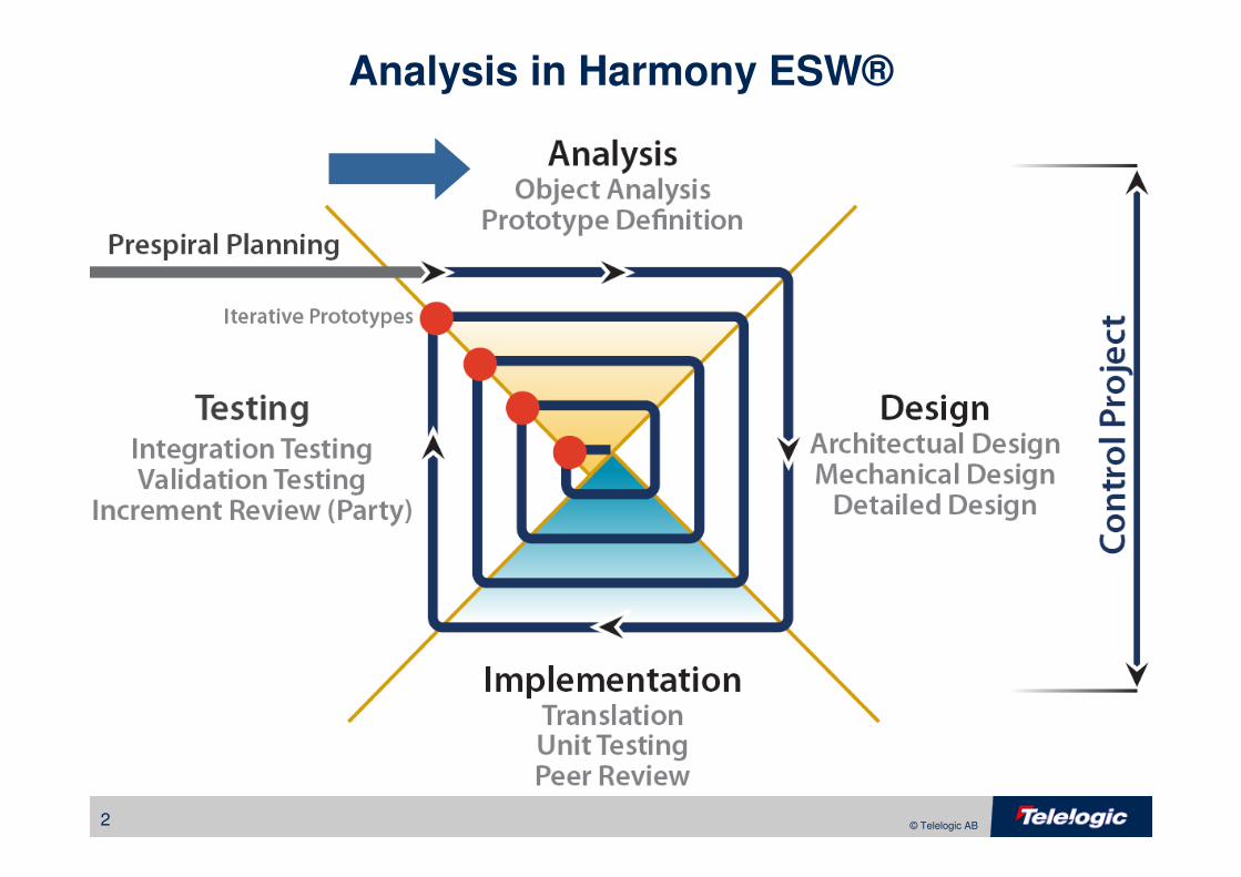
Analysis in Harmony ESW®
3 © Telelogic AB
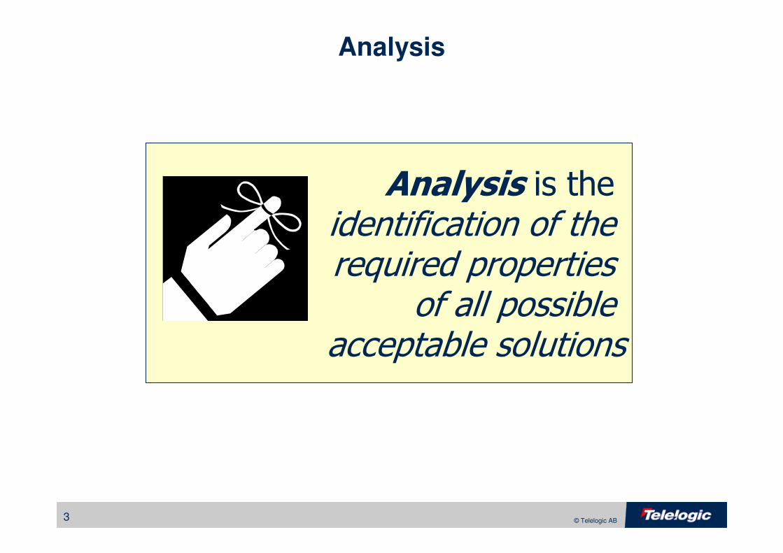
Analysis
Analysis is the identification of the required properties
of all possible acceptable solutions
4 © Telelogic AB
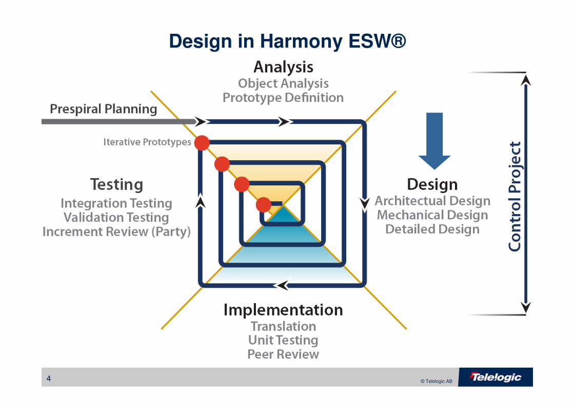
Design in Harmony ESW®
5 © Telelogic AB
Design
Design is the selectionof one particular solution which optimizes the setof design criteria with respect to the relative importance of each
6 © Telelogic AB
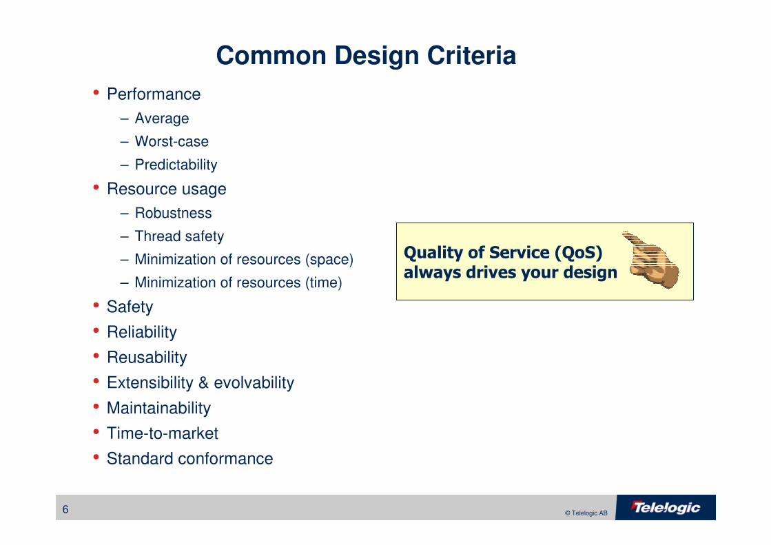
Common Design Criteria
• Performance
– Average
– Worst-case
– Predictability
• Resource usage
– Robustness
– Thread safety
– Minimization of resources (space)
– Minimization of resources (time)
• Safety
• Reliability
• Reusability
• Extensibility & evolvability
• Maintainability
• Time-to-market
• Standard conformance
Quality of Service (QoS) always drives your design
7 © Telelogic AB
Analysis
• What, not How
• Identify all properties that must exist in all acceptable solutions
• Requirements Analysis
– Identify black box functionality
– Use case and context views
• Object Analysis
– Identify essential object model
– Class, state and scenario views
8 © Telelogic AB
Design
• How analysis model will be implemented
• Identify and refine the properties of one particular (optimal) solution
• Two approaches
– Elaborative Design
Refine analysis model by adding more detail
– Translative Design
Build a translator that embodies design decisions
9 © Telelogic AB
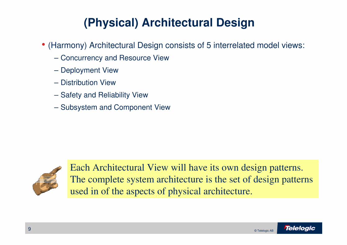
(Physical) Architectural Design
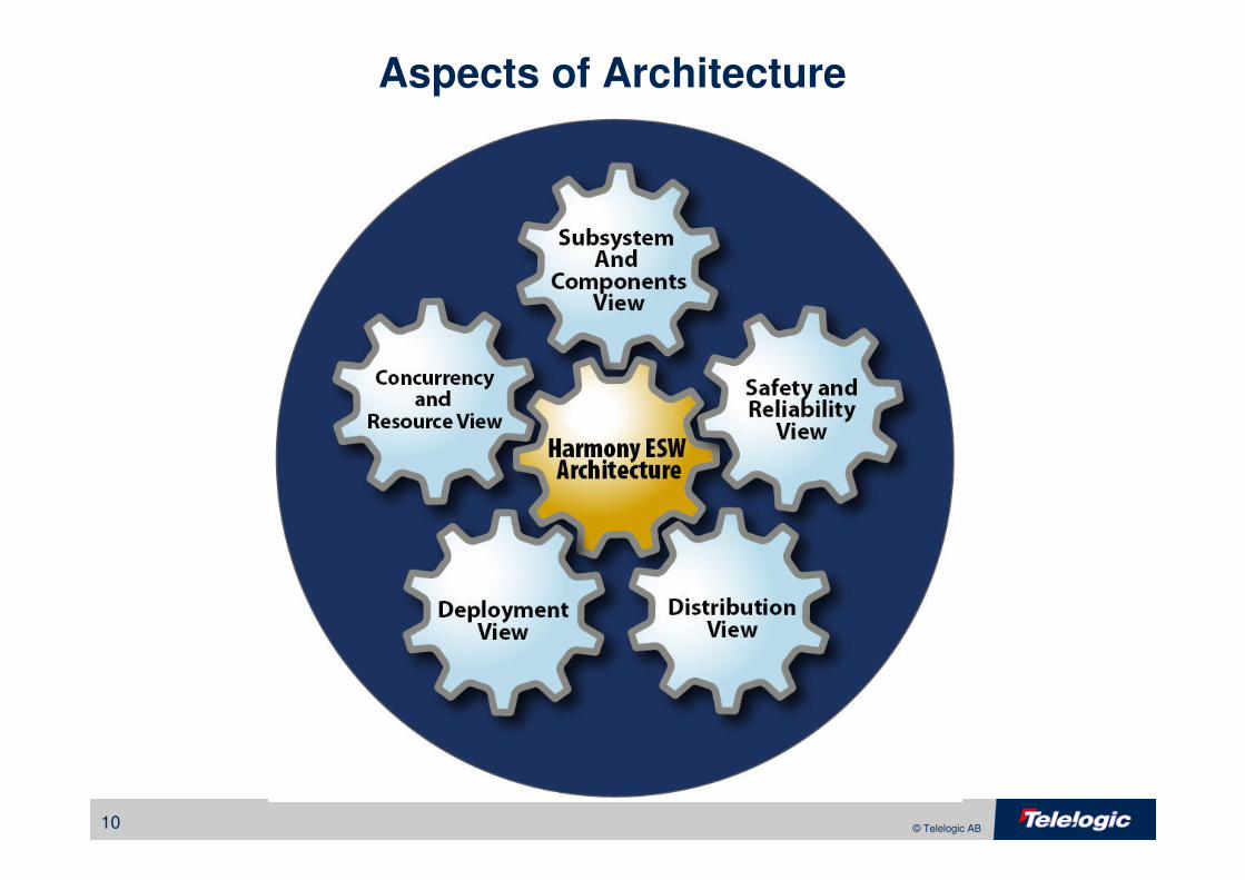
• (Harmony) Architectural Design consists of 5 interrelated model views:
– Concurrency and Resource View
– Deployment View
– Distribution View
– Safety and Reliability View
– Subsystem and Component View
Each Architectural View will have its own design patterns.
The complete system architecture is the set of design patterns
used in of the aspects of physical architecture.
10 © Telelogic AB
Aspects of Architecture
v 1.1 (c) Telelogic 2007 Do not copy or reproduce without permission11 © Telelogic AB
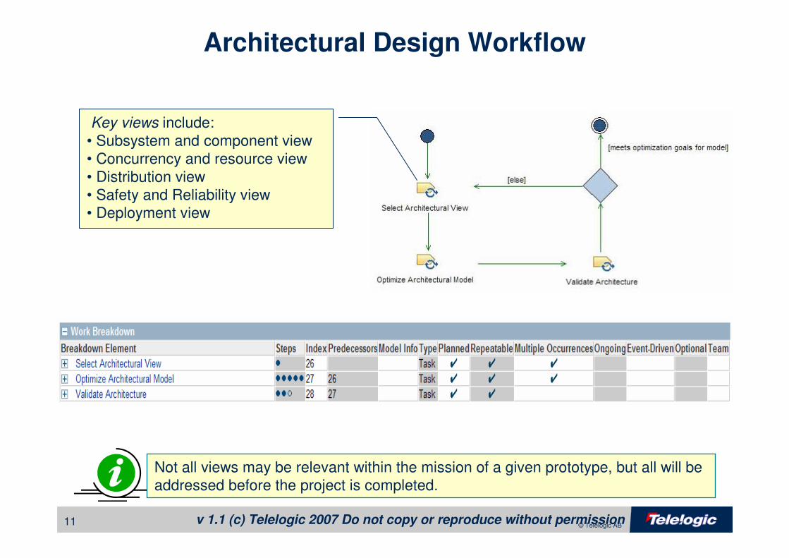
Architectural Design Workflow
Key views include:
• Subsystem and component view
• Concurrency and resource view
• Distribution view
• Safety and Reliability view
• Deployment view
Not all views may be relevant within the mission of a given prototype, but all will be
addressed before the project is completed.
v 1.1 (c) Telelogic 2007 Do not copy or reproduce without permission12 © Telelogic AB
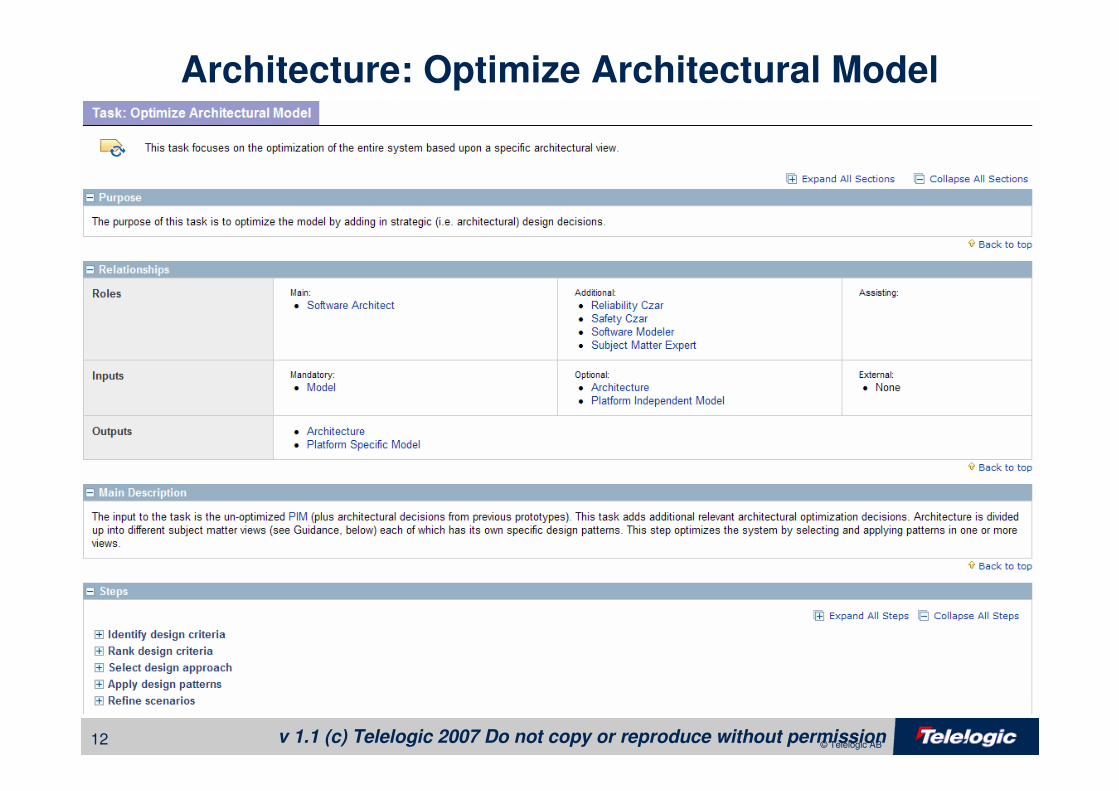
Architecture: Optimize Architectural Model
13 © Telelogic AB
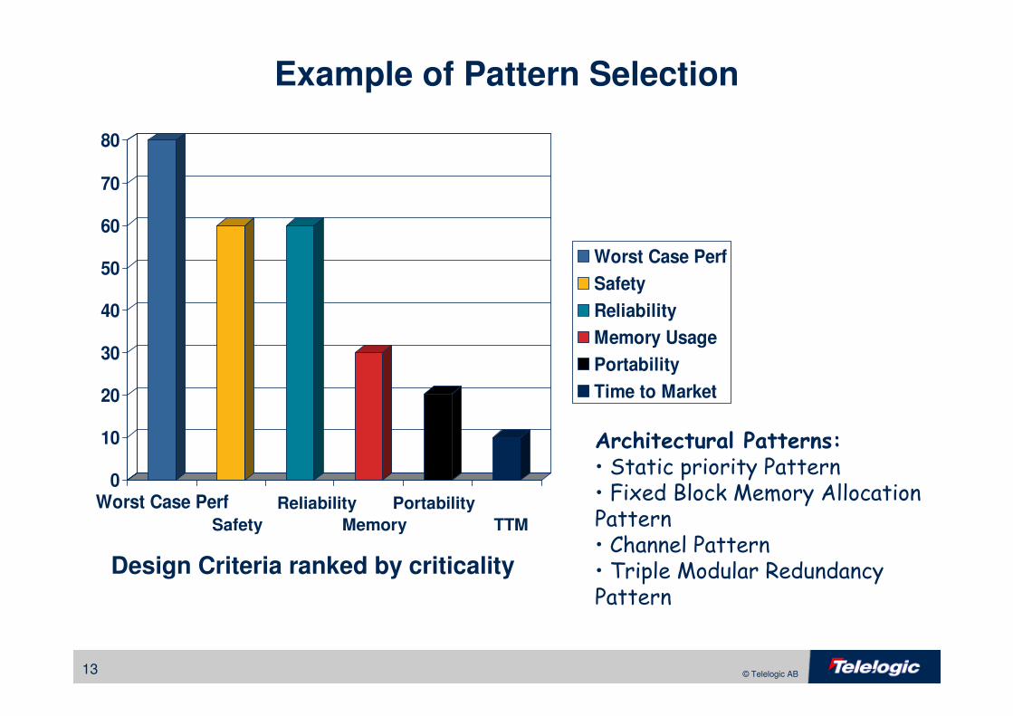
Example of Pattern Selection
0
10
20
30
40
50
60
70
80
Worst Case Perf
Worst Case Perf
Safety
Reliability
Memory Usage
Portability
Time to Market
Architectural Patterns:
• Static priority Pattern• Fixed Block Memory Allocation Pattern • Channel Pattern• Triple Modular Redundancy Pattern
Design Criteria ranked by criticality
Safety
Reliability
Memory
Portability
TTM
14 © Telelogic AB
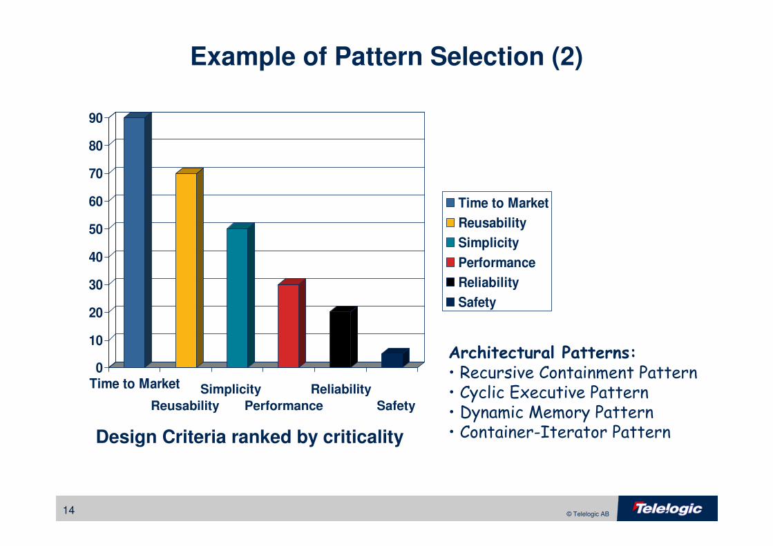
Example of Pattern Selection (2)
0
10
20
30
40
50
60
70
80
90
Time to Market
Time to Market
Reusability
Simplicity
Performance
Reliability
Safety
Architectural Patterns:
• Recursive Containment Pattern• Cyclic Executive Pattern• Dynamic Memory Pattern• Container-Iterator PatternDesign Criteria ranked by criticality
Reusability
Simplicity
Performance
Reliability
Safety
15 © Telelogic AB
Mechanistic Design
• Addition and refinement of objects to implement analysis models
• Addition of “glue” objects
– Containers and Collections
– Interfaces
– Medium-level policies
– Optimized rendezvous among threads
– Aid reuse by enforcing
• Good abstraction
• Good encapsulation
v 1.1 (c) Telelogic 2007 Do not copy or reproduce without permission16 © Telelogic AB
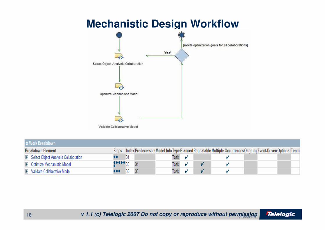
Mechanistic Design Workflow
v 1.1 (c) Telelogic 2007 Do not copy or reproduce without permission17 © Telelogic AB
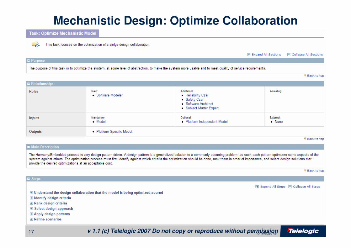
Mechanistic Design: Optimize Collaboration
18 © Telelogic AB
Detailed Design
• Refinement of details within objects themselves
– Visibility
– Internal decomposition of services
– Internal data structuring and typing
– Internal safety and reliability means
• Data redundancy
– Internal implementation policy of associations and object messaging

19 © Telelogic AB
Design Patterns
• Design patterns are
– generalized solutions to recurring optimization problems
– reified structures of object collaboration that reappear in a variety of
contexts
– Parameterized collaborations of objects, where the object roles are the
formal parameters and the objects that play those roles are the actual
parameters when the pattern is instantiated
• UML has introduced a notation to explicitly capture design patterns.
• Shown as a dotted ellipse with dotted lines to the collaborating objects or classes
20 © Telelogic AB
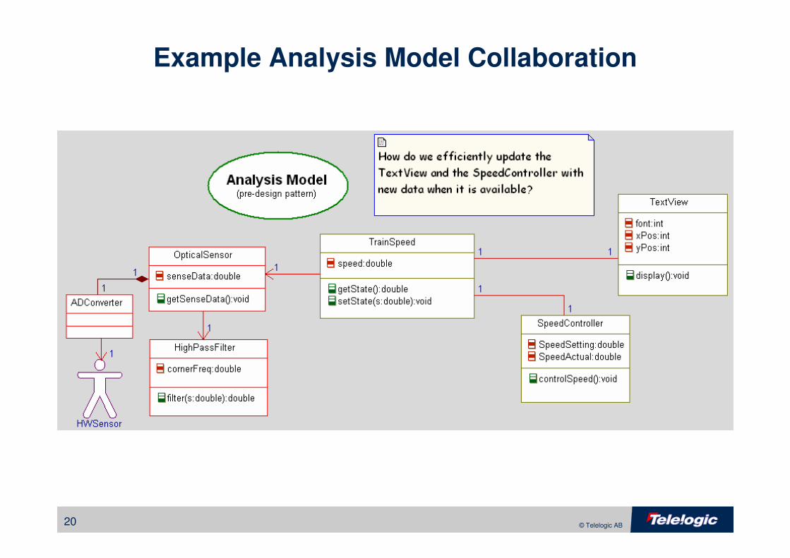
Example Analysis Model Collaboration
21 © Telelogic AB
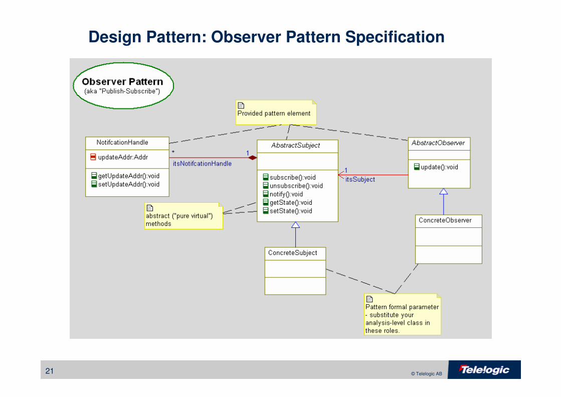
Design Pattern: Observer Pattern Specification
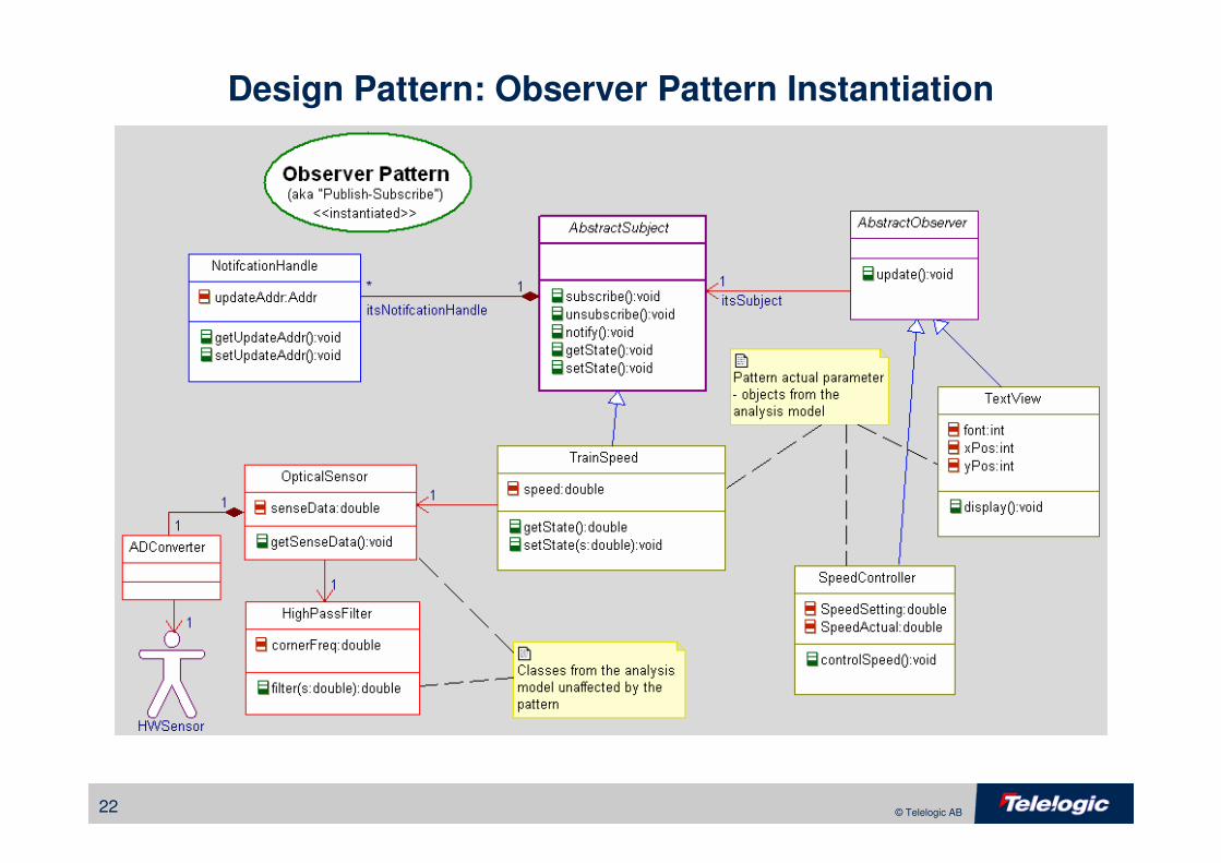
22 © Telelogic AB
Design Pattern: Observer Pattern Instantiation
23 © Telelogic AB
Why Use Design Patterns?
• Reuse effective design solutions
• Provide a more powerful vocabulary of design concepts to developers
• Develop “optimal” designs for specific design criteria
• Develop more understandable designs
24 © Telelogic AB
Properties of Design Patterns
• Problem Context
– Statement of the characteristics of a problem context that make the solution
useful
– Statement of the characteristics optimized by the solution
• Solution
– The design pattern per se
– Often shown as a class diagram with accompanying sequence and state
diagrams
– Often shown with a particular example application
• Consequences
– Design is all about optimization
– Every pattern has benefits and costs
• Benefits are optimizations that can be achieved using the pattern
• Costs are deoptimizations that result from the use of the pattern
25 © Telelogic AB
How do I Apply Design Patterns???
1. Construct the (working) initial model (PIM)
2. Identify the design criteria
3. Rank the design criteria in order of importance
4. Identify design patterns that optimize the system (architectural) or collaboration (mechanistic) for the critical design criteria at the expense of the lesser important ones
� Architectural patterns apply system-wide
� Mechanistic patterns apply collaboration-wide
� Detailed design patterns apply class-wide
5. Apply the design patterns
6. Test the (working) design solution (PSM)
� Is the original functionality retained?
� Are the desired optimizations achieved?
26 © Telelogic AB
A Brief Selection of Important Architectural Design Patterns
27 © Telelogic AB
Channel Pattern
• Problem
– Efficient execution of a system in which data is successively transformed in a
series of steps
– Want to organize and manage a hi-reliability, hi-availability, or safety-critical
system that must provide redundancy of end-to-end behaviors
• Solution
– Construct the system as a channel, a large scale subsystem which handles
data from acquisition all the way through dependent actuation. Provide as
many independent channels as necessary.
• Consequences
– A simple organizational pattern that permits redundancy to be easily added.
– May use additional memory since channels are designed to be independent,
requiring replication (redundancy)

28 © Telelogic AB
Channel Pattern
Input Filter Output FilterAbstract
Transformation
Output
Sink
«channel»
datum
[raw]
datum
[cooked]
datum
[partially cooked]
"Object in State" notationin the UML. State is insquare brackets.
Concrete
Transformation
transformacquire issue
29 © Telelogic AB
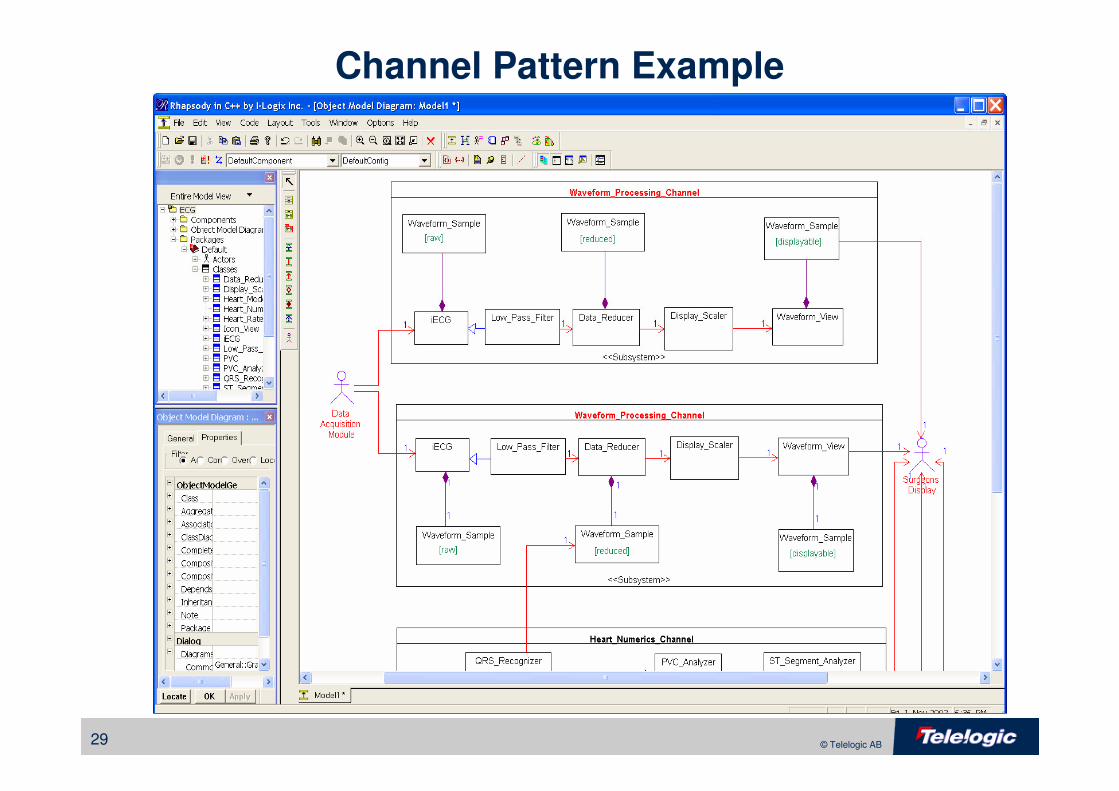
Channel Pattern Example
30 © Telelogic AB
Concurrency Architecture Patterns
31 © Telelogic AB
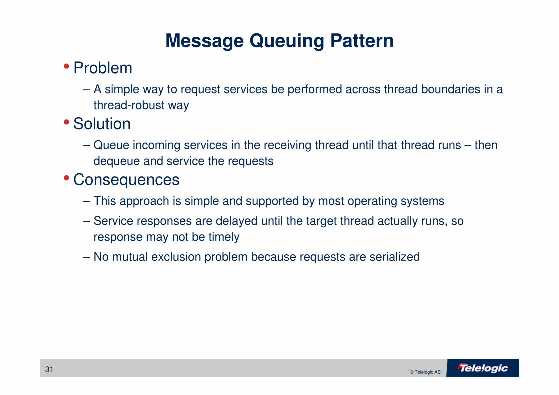
Message Queuing Pattern
• Problem
– A simple way to request services be performed across thread boundaries in a
thread-robust way
• Solution
– Queue incoming services in the receiving thread until that thread runs – then
dequeue and service the requests
• Consequences
– This approach is simple and supported by most operating systems
– Service responses are delayed until the target thread actually runs, so
response may not be timely
– No mutual exclusion problem because requests are serialized
32 © Telelogic AB
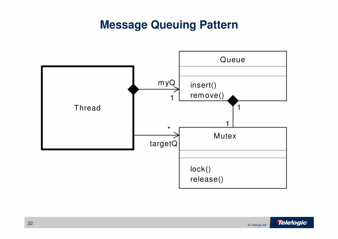
Message Queuing Pattern
Thread
myQ
targetQ
1
1
*
1
Mutex
lock()
release()
Queue
insert()
remove()
33 © Telelogic AB
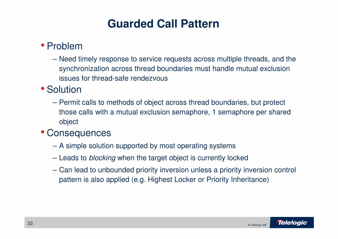
Guarded Call Pattern
• Problem
– Need timely response to service requests across multiple threads, and the
synchronization across thread boundaries must handle mutual exclusion
issues for thread-safe rendezvous
• Solution
– Permit calls to methods of object across thread boundaries, but protect
those calls with a mutual exclusion semaphore, 1 semaphore per shared
object
• Consequences
– A simple solution supported by most operating systems
– Leads to blocking when the target object is currently locked
– Can lead to unbounded priority inversion unless a priority inversion control
pattern is also applied (e.g. Highest Locker or Priority Inheritance)
34 © Telelogic AB
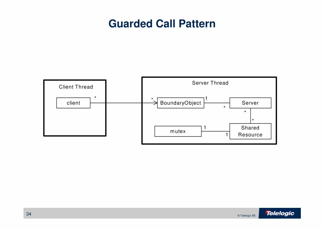
Guarded Call Pattern
mutex
BoundaryObjectclient
Client ThreadServer Thread
Server
1
1
*
1 Shared
Resource
*
*
* *
35 © Telelogic AB
Rendezvous Pattern
• Problem
– Need a collaboration structure that allows any arbitrary set of
preconditional invariants to be met for thread synchronization,
independent of task phasings, scheduling policies, and priorities.
• Solution
– Reify the rendezvous policy as a class that mediates how the threads
collaborate
• Consequences
– An easy-to-implement pattern that can implement an arbitrarily complex
set of thread rendezvous preconditions
– Thread Barrier Pattern is a common instantiation of this pattern
36 © Telelogic AB
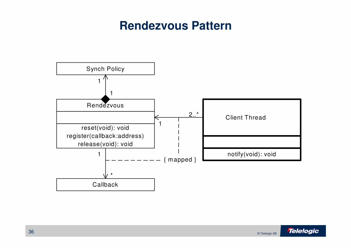
Rendezvous Pattern
Rendezvous
Client Thread
*
1reset(void): void
register(callback:address)
release(void): void
Callback
2..*
1{ mapped }
Synch Policy
1
1
notify(void): void
37 © Telelogic AB
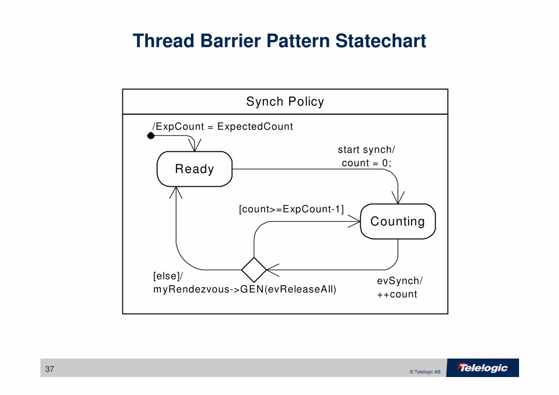
Thread Barrier Pattern Statechart
Synch Policy
Ready
Counting
start synch/
count = 0;
[count>=ExpCount-1]
[else]/
myRendezvous->GEN(evReleaseAll)
/ExpCount = ExpectedCount
evSynch/
++count
38 © Telelogic AB
Memory Patterns
• Pooled Allocation Pattern
• Fixed Sized Buffer Allocation Pattern
• Smart Pointer Pattern
39 © Telelogic AB
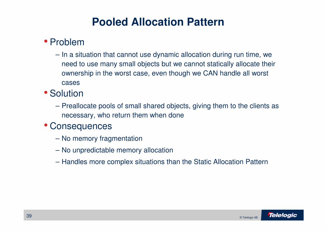
Pooled Allocation Pattern
• Problem
– In a situation that cannot use dynamic allocation during run time, we
need to use many small objects but we cannot statically allocate their
ownership in the worst case, even though we CAN handle all worst
cases
• Solution
– Preallocate pools of small shared objects, giving them to the clients as
necessary, who return them when done
• Consequences
– No memory fragmentation
– No unpredictable memory allocation
– Handles more complex situations than the Static Allocation Pattern
40 © Telelogic AB
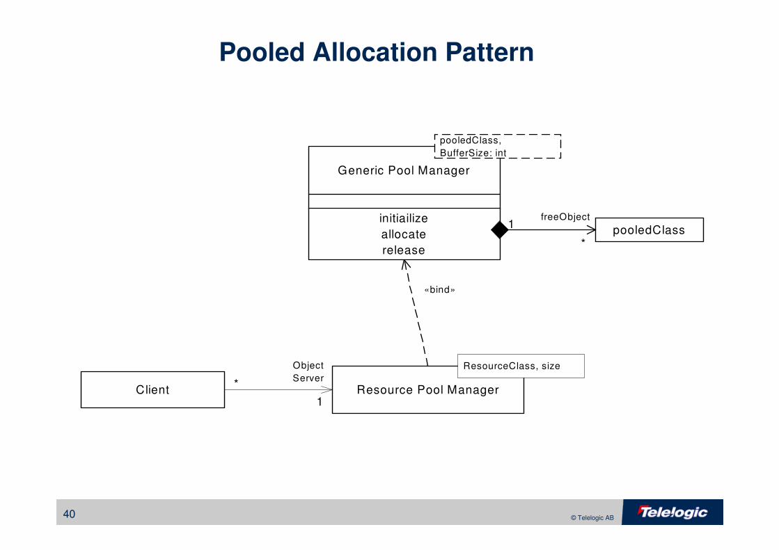
Pooled Allocation Pattern
Client1
Generic Pool Manager
initiailize
allocate
release
*
Object
Server
«bind»
pooledClass,
BufferSize: int
Resource Pool Manager
ResourceClass, size
pooledClass*
1freeObject
41 © Telelogic AB
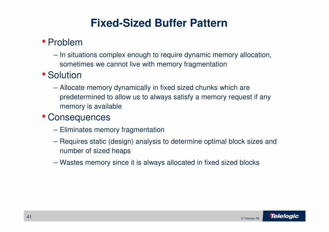
Fixed-Sized Buffer Pattern
• Problem
– In situations complex enough to require dynamic memory allocation,
sometimes we cannot live with memory fragmentation
• Solution
– Allocate memory dynamically in fixed sized chunks which are
predetermined to allow us to always satisfy a memory request if any
memory is available
• Consequences
– Eliminates memory fragmentation
– Requires static (design) analysis to determine optimal block sizes and
number of sized heaps
– Wastes memory since it is always allocated in fixed sized blocks
42 © Telelogic AB
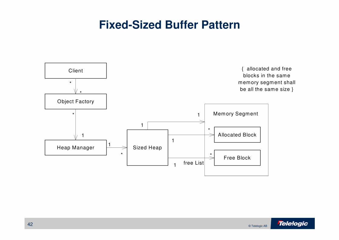
Fixed-Sized Buffer Pattern
Memory Segment
Heap Manager Sized Heap
Allocated Block
Free Block
Object Factory
Client
1
*
*
1
1
1
1
*
1
*
*
*
{ allocated and free
blocks in the same
memory segment shall
be all the same size }
free List
43 © Telelogic AB
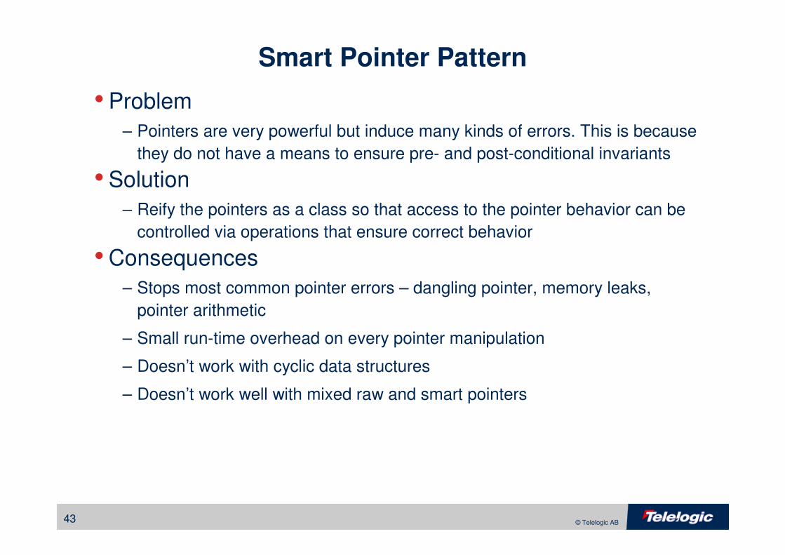
Smart Pointer Pattern
• Problem
– Pointers are very powerful but induce many kinds of errors. This is because
they do not have a means to ensure pre- and post-conditional invariants
• Solution
– Reify the pointers as a class so that access to the pointer behavior can be
controlled via operations that ensure correct behavior
• Consequences
– Stops most common pointer errors – dangling pointer, memory leaks,
pointer arithmetic
– Small run-time overhead on every pointer manipulation
– Doesn’t work with cyclic data structures
– Doesn’t work well with mixed raw and smart pointers
44 © Telelogic AB
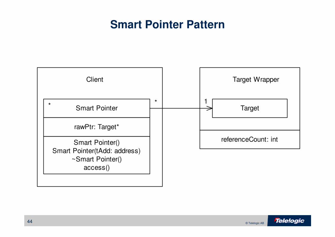
Smart Pointer Pattern
* 1TargetSmart Pointer
Client
*
rawPtr: Target*
Smart Pointer()
Smart Pointer(tAdd: address)
~Smart Pointer()
access()
referenceCount: int
Target Wrapper
45 © Telelogic AB
Distribution Patterns
• Observer Pattern
• Proxy Pattern
• Broker Pattern
46 © Telelogic AB
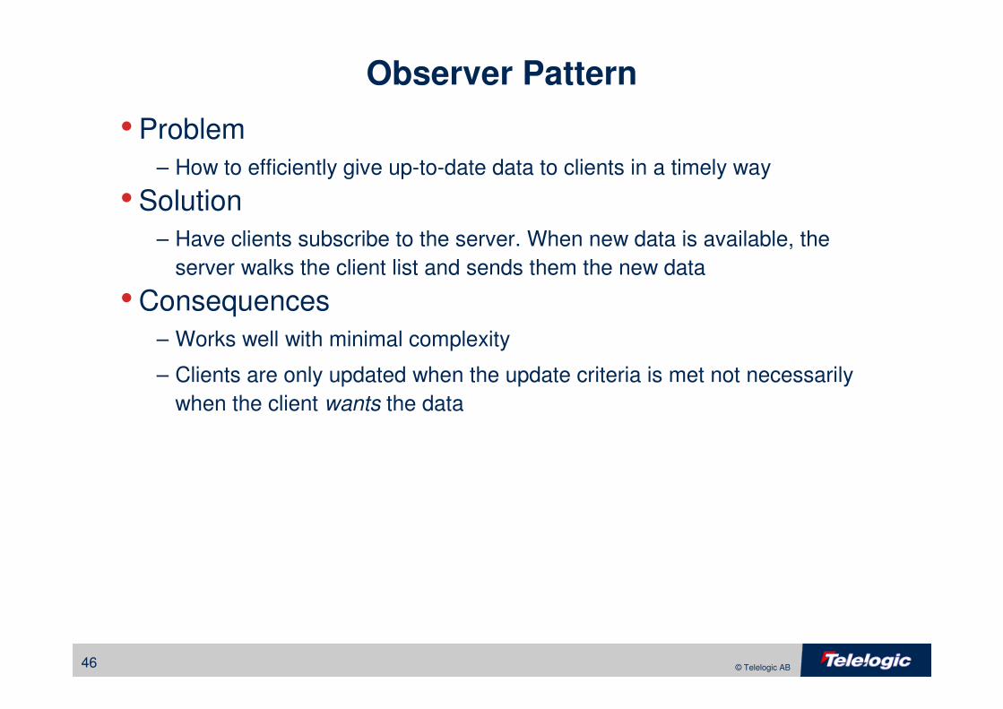
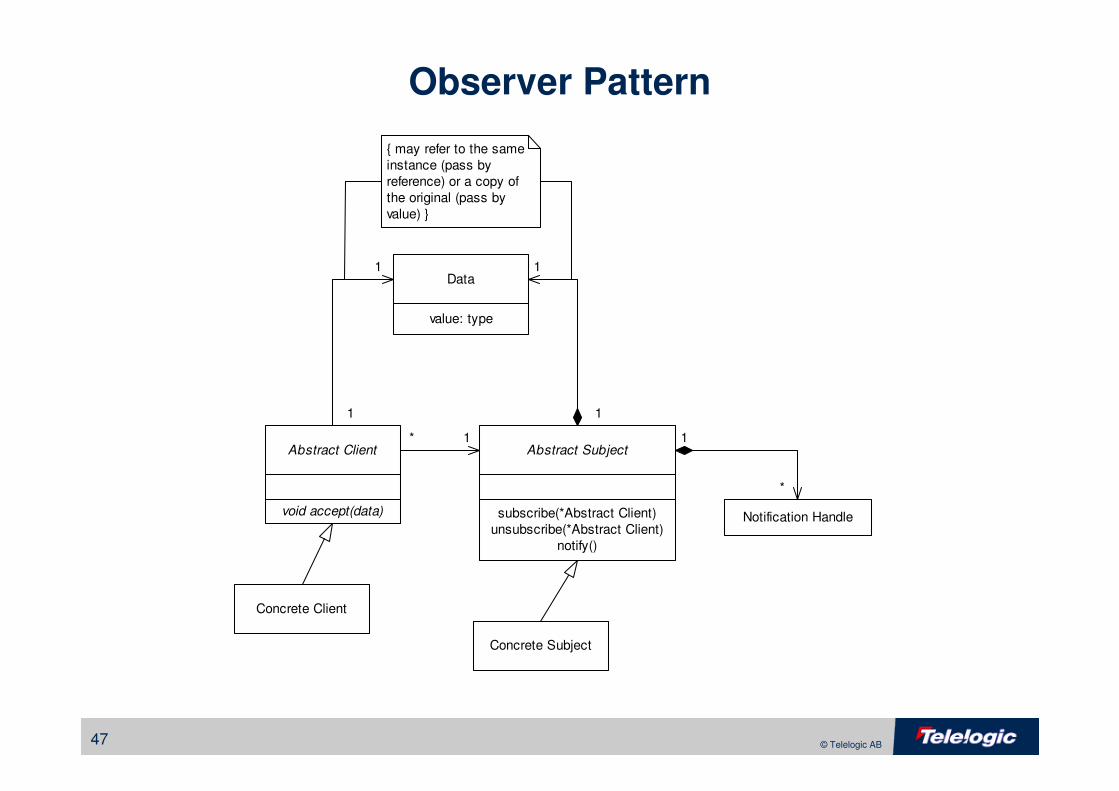
Observer Pattern
• Problem
– How to efficiently give up-to-date data to clients in a timely way
• Solution
– Have clients subscribe to the server. When new data is available, the
server walks the client list and sends them the new data
• Consequences
– Works well with minimal complexity
– Clients are only updated when the update criteria is met not necessarily
when the client wants the data
47 © Telelogic AB
Observer Pattern
Concrete Subject
Abstract Subject
Notification Handle
Abstract Client
subscribe(*Abstract Client)
unsubscribe(*Abstract Client)
notify()
* 1 1
*
Concrete Client
void accept(data)
Data
value: type
1
1 1
1
{ may refer to the same
instance (pass by
reference) or a copy of
the original (pass by
value) }
48 © Telelogic AB
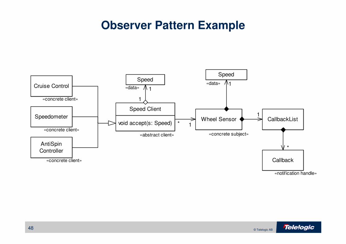
Observer Pattern Example
Wheel Sensor
Cruise Control
Speedometer
AntiSpin
Controller
CallbackList
Callback
*
1
1
Speed
1
Speed Client
void accept(s: Speed)
Speed
1
«concrete subject»«abstract client»
«concrete client»
«concrete client»
«concrete client»
«data»«data»
«notif ication handle»
*
1
49 © Telelogic AB
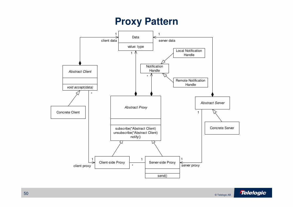
Proxy Pattern
• Problem
– Use an observer pattern across multiple address spaces with a variety of
different servers and clients, isolating away the knowledge of the
infrastructure of the means to communicate
• Solution
– Similar to a observer pattern but with client and server proxies to isolate the
required infrastructure
• Consequences
– A simple adaptation of the observer pattern
– Good isolation of subject from communications
– Optimizes bus traffic
50 © Telelogic AB
Proxy Pattern
Abstract Proxy
Client-side Proxy
Notification
HandleAbstract Client
*
1
Concrete Client
void accept(data)
Data
value: type
1
1
1
Concrete Server
1
*
1
server dataclient data
*
client proxy server proxyServer-side Proxy
1
*
Abstract Server
subscribe(*Abstract Client)
unsubscribe(*Abstract Client)
notify()
Local Notification
Handle
Remote Notification
Handle
send()
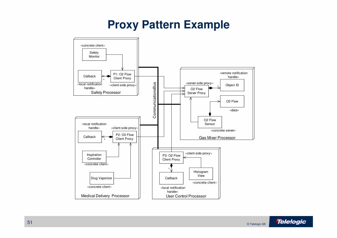
51 © Telelogic AB
Proxy Pattern Example
«concrete server»
«concrete client»
Safety
Monitor
Safety Processor
Medical Delivery Processor User Control Processor
Gas Mixer Processor
O2 Flow
Sensor
Inspiration
Controller
O2 Flow
Server Proxy
«server-side proxy»
P2: O2 Flow
Client Proxy
P3: O2 Flow
Client Proxy
P1: O2 Flow
Client Proxy
Histogram
ViewDrug Vaporizer Callback
Callback
Callback
Object ID
«concrete client»
«concrete client»
«local notification
handle»
«local notification
handle»
«local notification
handle»
«remote notification
handle»
«client-side proxy»
«client-side proxy»
«client-side proxy»
*
*
*
*
Co
mm
un
ica
tio
ns B
us
«concrete client»
O2 Flow
«data»
52 © Telelogic AB
Broker Pattern
• Problem
– Support a symmetric distribution architecture (as for dynamic load
balancing), and allow objects to find each other without knowing their
locations a priori
• Solution
– Add a broker as an object repository, such that when servers run, they
register with the broker; when clients need to access a server, they request
the location of the server from the broker
• Consequences
– Good support for symmetric architectures
– Good commercial support with CORBA
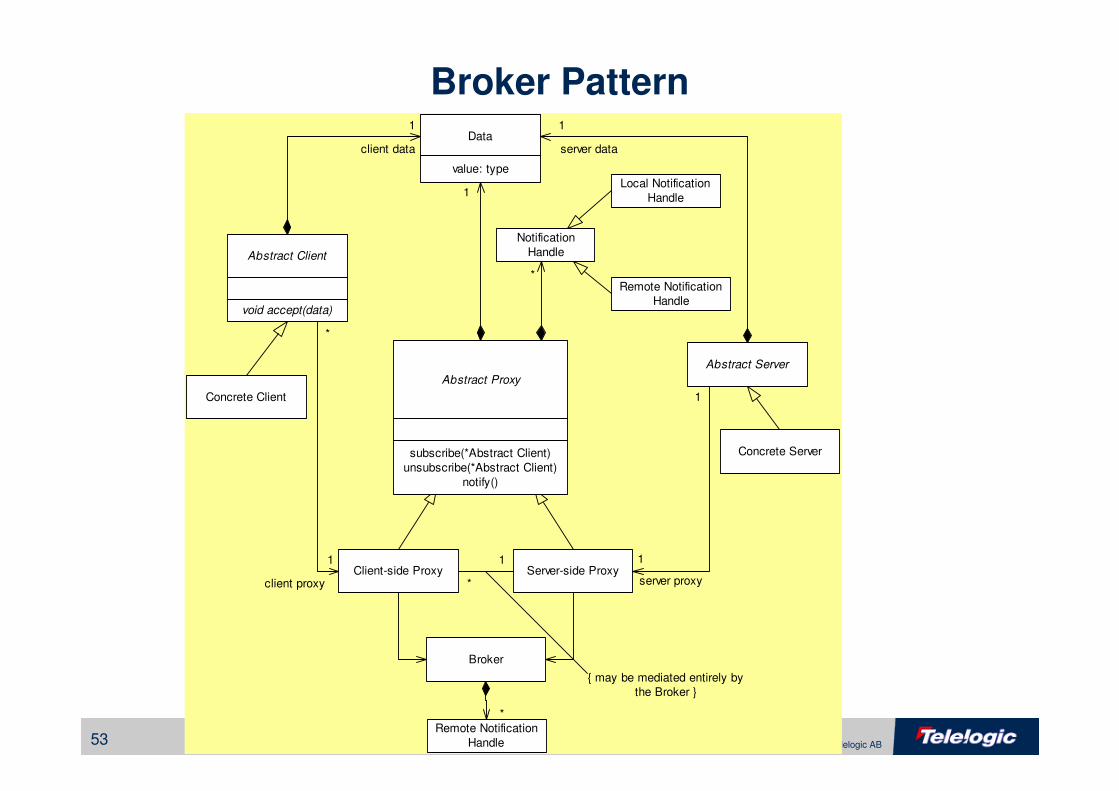
53 © Telelogic AB
Broker Pattern
Abstract Proxy
Client-side Proxy
Notification
HandleAbstract Client
*
1
Concrete Client
void accept(data)
Data
value: type
1
1
1
Concrete Server
1
*
1
server dataclient data
*
client proxy server proxyServer-side Proxy
1
*
Abstract Server
subscribe(*Abstract Client)
unsubscribe(*Abstract Client)
notify()
Local Notification
Handle
Remote Notification
Handle
Broker
Remote Notification
Handle
*
{ may be mediated entirely by
the Broker }
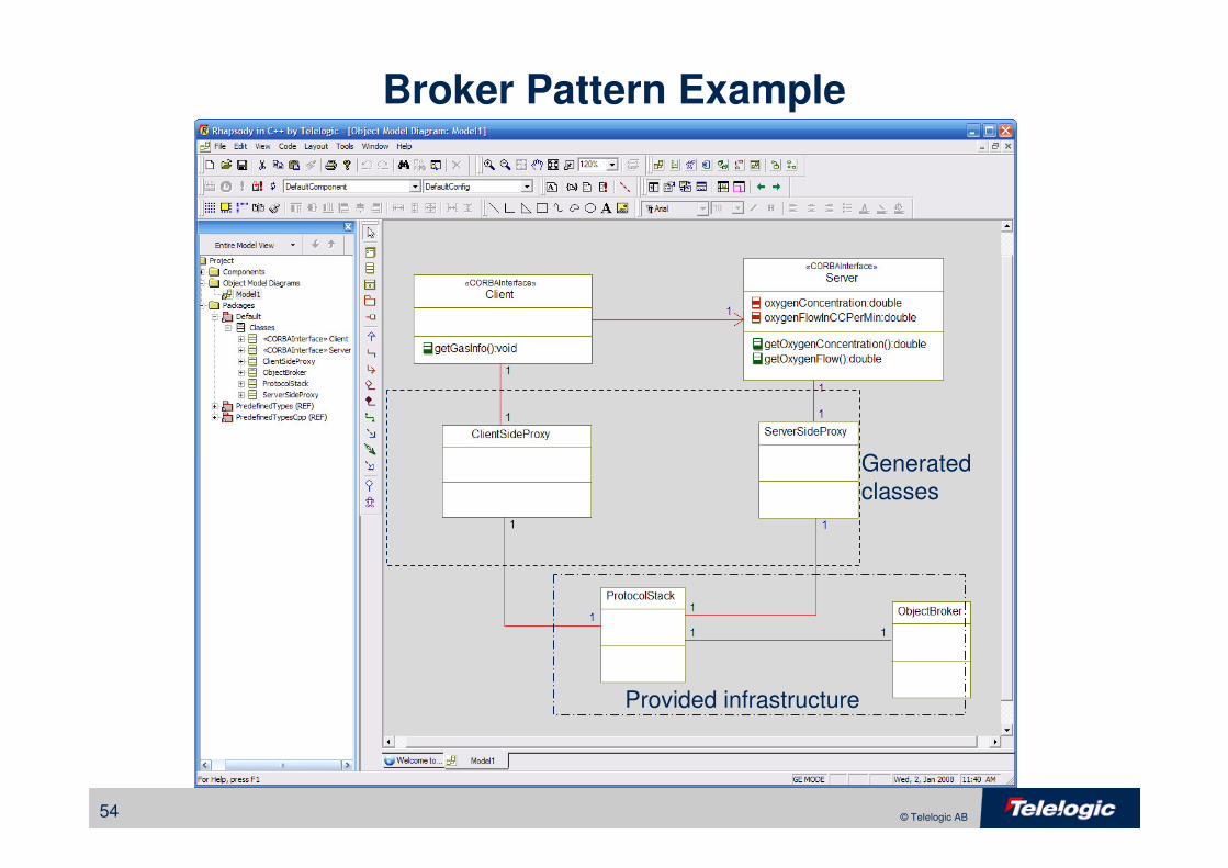
54 © Telelogic AB
Broker Pattern Example
Generated
classes
Provided infrastructure
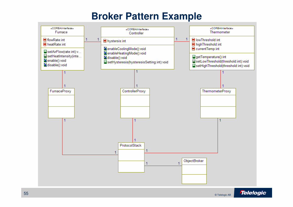
55 © Telelogic AB
Broker Pattern Example
56 © Telelogic AB
Safety and Reliability Patterns
• Protected Single Channel Pattern
• Homogeneous Redundancy Pattern
• Triple Modular Redundancy Pattern
57 © Telelogic AB
Safety and Reliability
• Reliability is measured by MTBF
– MTBF = probability of being able to deliver functionality
– Reliability is a stochastic measure
• Safety is measured by risk
– risk = severityfault * likelihoodfault
• Fault is nonconformant behavior
– Error: a design or implementation flaw
• Hardware
• Software
– Failure: breakage of something that was previously correct
• Hardware only
58 © Telelogic AB
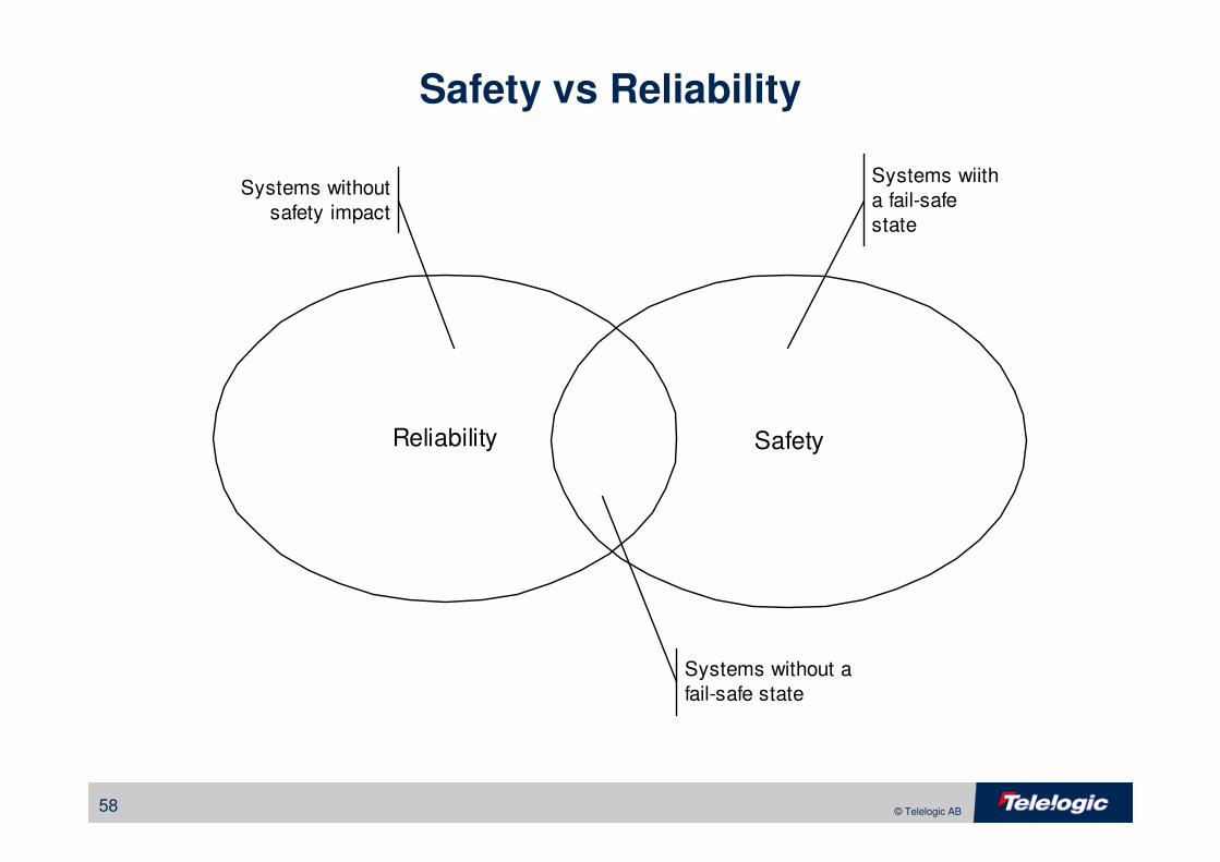
Safety vs Reliability
SafetyReliability
Systems without a
fail-safe state
Systems wiith
a fail-safe
state
Systems without
safety impact
59 © Telelogic AB
Protected Single Channel Pattern
• Problem
– Provide protection against errors (design flaws) in a cost effective way
• Solution
– A variant of the Channel pattern the uses light-weight redundancy to
provide identification of errors
• Consequences
– Low design cost
– Low recurring cost
– Not able to continue in the presence of faults
60 © Telelogic AB
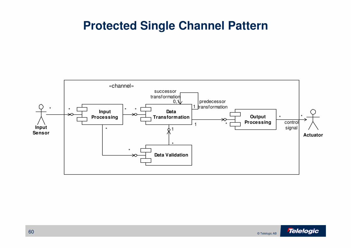
Protected Single Channel Pattern
InputProcessing
DataTransformation Output
ProcessingInput
Sensor Actuator
Data Validation
controlsignal
«channel»
* * * *
*
*
*
1
1
*
* *
1
0,1
successortransformation
predecessortransformation
61 © Telelogic AB
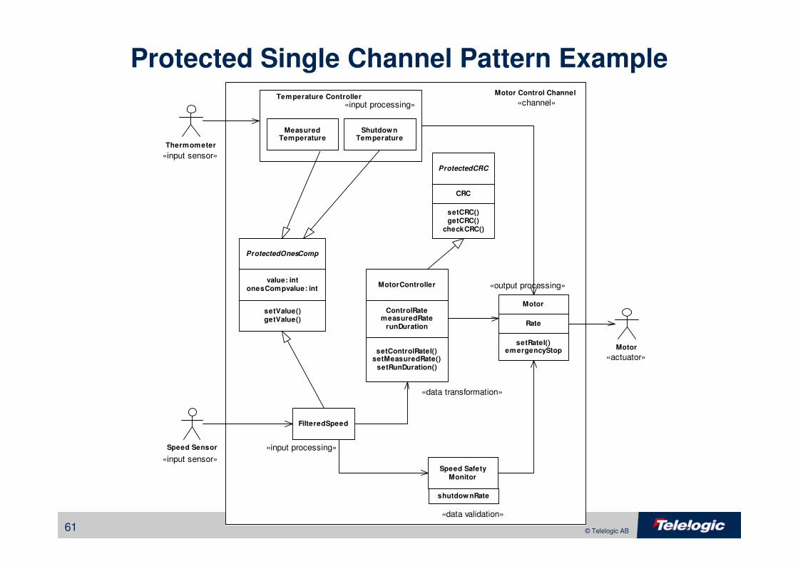
Protected Single Channel Pattern Example
Speed Sensor
Motor
Thermometer
Motor
Rate
ProtectedCRC
CRC
setCRC()getCRC()
checkCRC()
setRateI()emergencyStop
FilteredSpeed
ProtectedOnesComp
value: intonesCompvalue: int
setValue()getValue()
MotorController
ControlRatemeasuredRate
runDuration
setControlRateI()setMeasuredRate()
setRunDuration()
Speed SafetyMonitor
«output processing»
«input processing»
«input processing»
«data transformation»
«data validation»
«input sensor»
«input sensor»
«actuator»
shutdownRate
Temperature Controller
MeasuredTemperature
ShutdownTemperature
Motor Control Channel
«channel»
62 © Telelogic AB
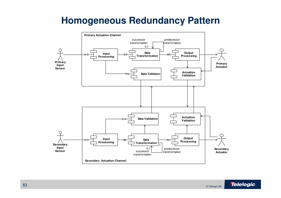
Homogeneous Redundancy Pattern
• Problem
– Provide the ability to continue in the presence of a fault
• Solution
– Provide “redundancy in the large” by replicating channels
• Consequences
– Low design-time cost
– High recurring cost
– Able to continue in the presence of a failure
– Does not recover from errors
63 © Telelogic AB
Homogeneous Redundancy Pattern
InputProcessing
OutputProcessing
PrimaryInput
Sensor
Data Validaton
Primary Actuation Channel
ActuationValidation
PrimaryActuator
DataTransformation
OutputProcessing
Data ValidationActuationValidation
SecondaryActuator
InputProcessing
SecondaryInput
Sensor
DataTransformation
Secondary Actuation Channel
10,1
successortransformation
predecessortransformation
1
0,1successor
transformation
predecessortransformation
64 © Telelogic AB
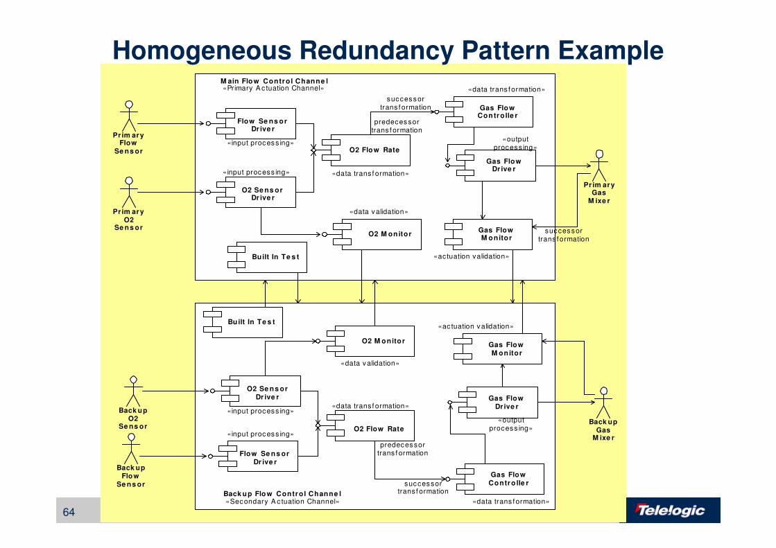
O2 Se ns orDr ive r
Gas FlowControlle r
Gas FlowDr ive r
Pr im aryO2
Se ns orO2 M onitor
M ain Flow Control Channe l
Gas FlowM onitor
Pr im aryGas
M ixe r
Flow Se ns orDr ive r
Pr im aryFlow
Se ns or O2 Flow Rate
O2 Se ns orDr ive r
Gas FlowContro lle r
Gas FlowDr ive r
Back upO2
Se ns or
O2 M onitorGas FlowM onitor
Back upGas
M ixe r
Flow Se ns orDr ive r
Back upFlow
Se ns or
O2 Flow Rate
Back up Flow Control Channe l
successortrans formation
predecessortrans f ormation
predecessortrans f ormation
successortransf ormation
«input process ing»
«input process ing»
«input process ing»
«input process ing»
«data validation»
«data validation»
«data transf ormation»
«data trans formation»
«outputprocess ing»
«outputprocess ing»
«ac tuation validation»
«actuation validation»
«Primary A c tuation Channel»
«Secondary A c tuation Channel» «data trans formation»
successortrans formation
«data transf ormation»
Built In Te s t
Built In Te s t
Homogeneous Redundancy Pattern Example
65 © Telelogic AB
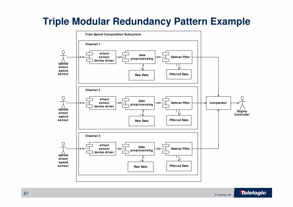
Triple Modular Redundancy Pattern
• Problem
– Want to provide protection against single point failures and be able to
continue
• Solution
– Replicate the channel three times, run all three in parallel
– If one channel breaks, then the other two will concur
• Consequences
– A common solution to redundancy
– Low design cost
– Very high recurring cost
– Good support for failures but not for errors
66 © Telelogic AB
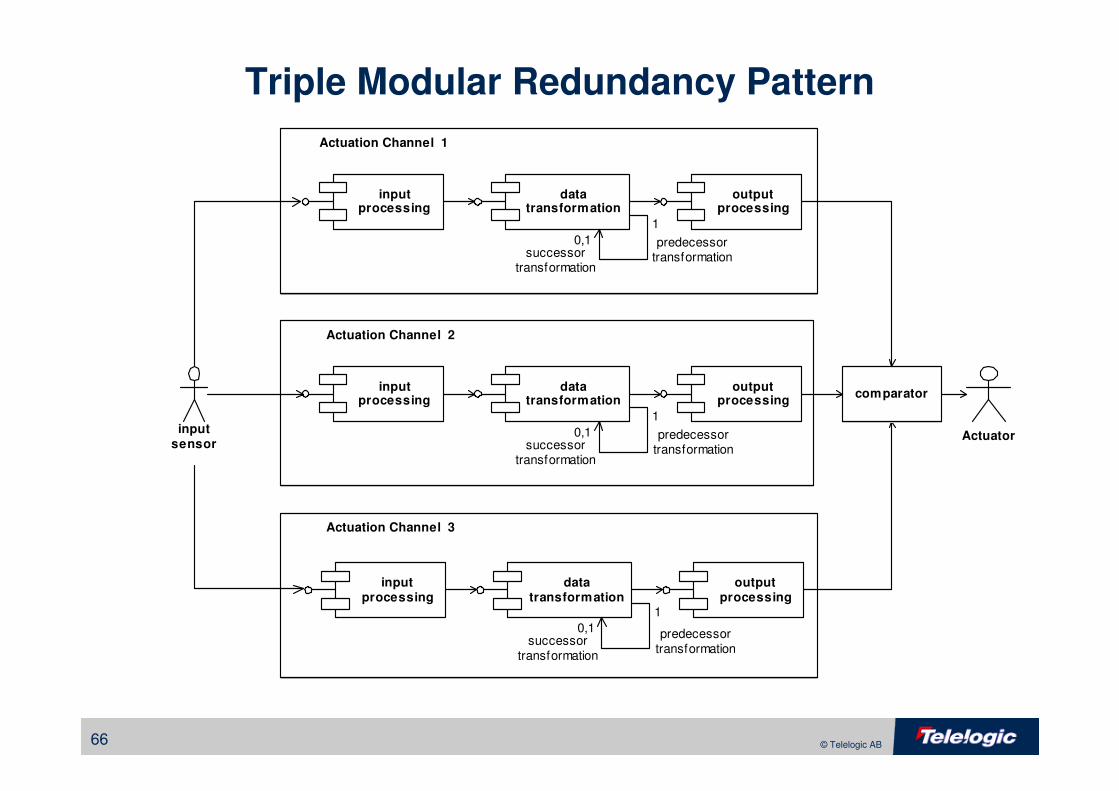
Triple Modular Redundancy Pattern
inputprocessing
datatransformation
outputprocessing
inputsensor
Actuator
inputprocessing
datatransformation
outputprocessing
inputprocessing
datatransformation
outputprocessing
comparator
Actuation Channel 3
0,1successor
transformation
predecessortransformation
1
0,1successor
transformation
predecessortransformation
1
0,1successor
transformation
predecessortransformation
1
Actuation Channel 2
Actuation Channel 1
67 © Telelogic AB
Triple Modular Redundancy Pattern Example
wheelsensor
device driver
datapreprocessing
EngineController
comparator
1
Channel 1
opticalwheelspeed
sensor Raw Data Filtered Data
Kalman Filter
1
* *
Train Speed Computation Subsystem
wheelsensor
device driver
datapreprocessing
1
Channel 2
opticalwheelspeed
sensor Raw Data Filtered Data
Kalman Filter
1
* *
wheelsensor
device driver
datapreprocessing
1
Channel 3
opticalwheelspeed
sensor Raw Data Filtered Data
Kalman Filter
1
* *
68 © Telelogic AB
Real-Time Pattern References
White papers on RT UML and related topics at www.telelogic.com/modeling