Embed Size (px)
Citation preview

Real-time advanced AVO seismic processing
QCs for validation of key processing steps
Stavanger,
27th of January 2016
FORCE Seminar
Mathieu DENTI
Senior Geoscientist Team Leader, Norway Scope

Introduction (1/2):
Advanced seismic processing QCs were implemented during the seismic imaging
project in order to monitor the AVO behavior of the seismic data after key
processing steps;
Conducted on the CGG Multi-Client New Ventures Horda 2014 dataset;
Objective: is the Zoeppritz compliancy of the data preserved or improved so that
accurate quantitative interpretation of processing outputs can be attempted
following the seismic processing?
Introduction (2/2):
4 different key processing steps were selected during the course of the signal
processing to conduct these QCs:
Step 1: after pre-migration Radon;
Step 2: after 5D signal enhancement (far trace denoise + destriping, shot/channel
amplitude correction, common offset denoise + demultiple and intrabed multiple
attenuation);
Step 3: after F-XY denoise;
Step 4: after dip filtering and RMO correction.

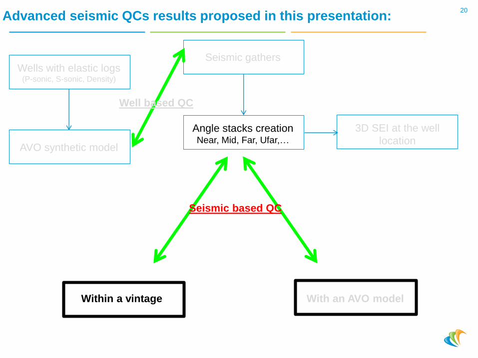
Advanced seismic QCs results proposed in this presentation:4
Seismic gathers
Angle stacks creationNear, Mid, Far, Ufar,…
Wells with elastic logs (P-sonic, S-sonic, Density)
Within a vintage With an AVO model
AVO synthetic model
Well based QC
3D SEI at the well
location
Seismic based QC

Advanced seismic QCs results proposed in this presentation:5
Seismic gathers
Angle stacks creationNear, Mid, Far, Ufar,…
Wells with elastic logs (P-sonic, S-sonic, Density)
Within a vintage With an AVO model
AVO synthetic model
Well based QC
3D SEI at the well
location
Seismic based QC

Objective and key observations to be done during those QCs:
AVO synthetic versus offset gathers:
– Is the seismic AVO trend consistent with the synthetic AVO trend?
– Do we observe an increase of the correlation between the seismic AVO fit and the AVO synthetic?
Inversion analysis at the well location:
– Does the correlation between inverted attributes and well logs increase?
6

Well 35/9-5: location
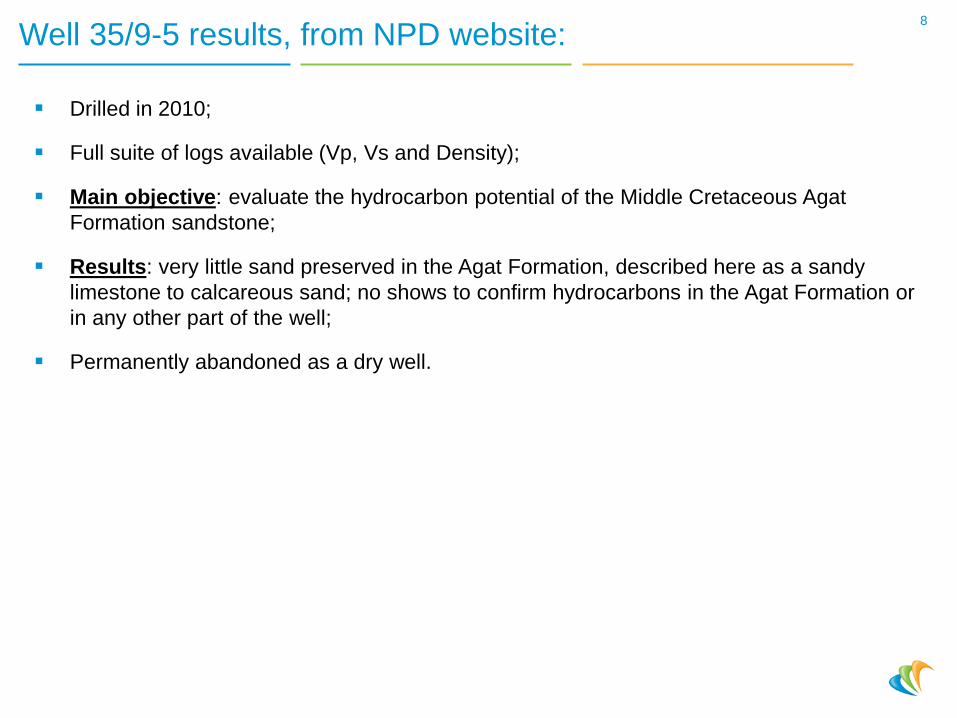
Well 35/9-5 results, from NPD website:
Drilled in 2010;
Full suite of logs available (Vp, Vs and Density);
Main objective: evaluate the hydrocarbon potential of the Middle Cretaceous Agat
Formation sandstone;
Results: very little sand preserved in the Agat Formation, described here as a sandy
limestone to calcareous sand; no shows to confirm hydrocarbons in the Agat Formation or
in any other part of the well;
Permanently abandoned as a dry well.
8
9
Am
plit
ude
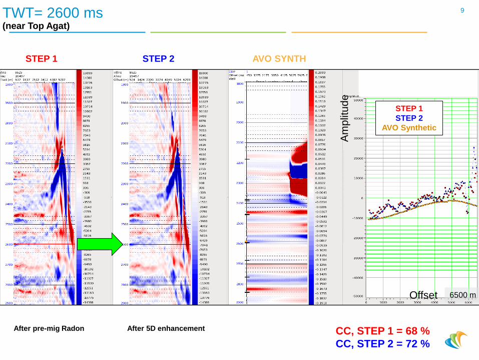
TWT= 2600 ms(near Top Agat)
STEP 1
STEP 2
AVO Synthetic
After pre-mig Radon After 5D enhancement
STEP 1 STEP 2 AVO SYNTH
CC, STEP 1 = 68 %
CC, STEP 2 = 72 %
Offset 6500 m

10
Am
plit
ude
TWT= 2600 ms(near Top Agat)
STEP 2
STEP 3
AVO Synthetic
Offset 6500 m
After 5D enhancement After F-XY denoise
STEP 2 STEP 3 AVO SYNTH
CC, STEP 3 = 74 %
11
Am
plit
ude
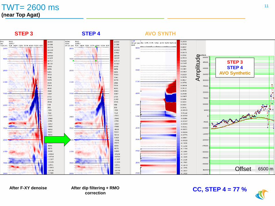
TWT= 2600 ms(near Top Agat)
STEP 3
STEP 4
AVO Synthetic
After F-XY denoise After dip filtering + RMO
correction
STEP 3 STEP 4 AVO SYNTH
Offset 6500 m
CC, STEP 4 = 77 %

12
Am
plit
ude
TWT= 2825 ms(near Top Krossfjord FM)
STEP 1
STEP 2
AVO Synthetic
After pre-mig Radon After 5D enhancement
STEP 1 STEP 2 AVO SYNTH
Offset 6500 m
CC, STEP 1 = 69 %
CC, STEP 2 = 71 %
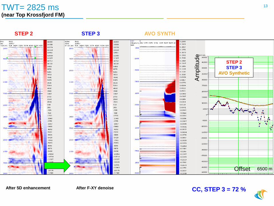
13
Am
plit
ude
TWT= 2825 ms(near Top Krossfjord FM)
STEP 2
STEP 3
AVO Synthetic
After 5D enhancement After F-XY denoise
STEP 2 STEP 3 AVO SYNTH
Offset 6500 m
CC, STEP 3 = 72 %

14
Am
plit
ude
TWT= 2825 ms(near Top Krossfjord FM)
STEP 3
STEP 4
AVO Synthetic
After F-XY denoise After dip filtering + RMO
correction
STEP 3 STEP 4 AVO SYNTH
Offset 6500 m
CC, STEP 4 = 76 %

Inversion analysis at the well location:Step 1 > pre-mig Radon
15
Vp Vs Density IpVp/Vs
ratioNear Mid Far UFar
Well logs
Upscaled well logs
Inverted attributes
Initial model
Seismic traces
Synthetic created from well logs
Synthetic from inverted attributes
CC (upscaled well logs
versus inverted
attributes)
Ip = 83,2%
Vp/Vs ratio = 49,0 %

16
Vp Vs Density IpVp/Vs
ratioNear Mid Far UFar
Seismic traces
Synthetic created from well logs
Synthetic from inverted attributes
Well logs
Upscaled well logs
Inverted attributes
Initial model
CC (upscaled well logs
versus inverted
attributes)
Ip = 85,7%
Vp/Vs ratio = 56,2 %
Inversion analysis at the well location:Step 2 > 5D signal enhancement

17
Vp Vs Density IpVp/Vs
ratioNear Mid Far UFar
Seismic traces
Synthetic created from well logs
Synthetic from inverted attributes
Well logs
Upscaled well logs
Inverted attributes
Initial model
CC (upscaled well logs
versus inverted
attributes)
Ip = 85,7%
Vp/Vs ratio = 56,6 %
Inversion analysis at the well location:Step 3 > F-XY denoise

18
Seismic traces
Synthetic created from well logs
Synthetic from inverted attributes
Vp Vs Density IpVp/Vs
ratioNear Mid Far UFar
Well logs
Upscaled well logs
Inverted attributes
Initial model
CC (upscaled well logs
versus inverted
attributes)
Ip = 86,4%
Vp/Vs ratio = 58,1 %
Inversion analysis at the well location:Step 4 > Dip filter + RMO corr.

Observations/Conclusions:
Less amplitude dispersion as we proceed through the processing sequence;
Amplitude trend consistent with prediction coming from the AVO model;
Increased correlation between inverted attributes and upscaled well logs;
Limitation: observation valid only at the well location.
19
Advanced seismic QCs results proposed in this presentation:20
Seismic gathers
Angle stacks creationNear, Mid, Far, Ufar,…
Wells with elastic logs (P-sonic, S-sonic, Density)
Within a vintage With an AVO model
AVO synthetic model
Well based QC
3D SEI at the well
location
Seismic based QC

Objective and key observations to be done during those QCs:
Is the repeatability between angle stacks increasing?
Is this behaviour seen for a «statistically meaningful» population of traces?
21

Comparison between one reference angle stack and other angle stacks:
Methodology:22
Reference
stackOther
stacksCC and NRMS

Angle stacks: Step 1 > pre-mig Radon
23
Near Mid Far Ufar

24
Near Mid Far Ufar
Angle stacks: Step 4 > Dip filter + RMO corr.

25
Correlation Coefficient:
Normalized Root Mean Square:
2
NRMS1CC
2
Lower Bound:
Couple of traces to be comparedCC
NRMS
BσAσ
BA,CovBA,CC
BRMS ARMS
B-ARMS 2BA,NRMS
Statistical measurements:
Mid
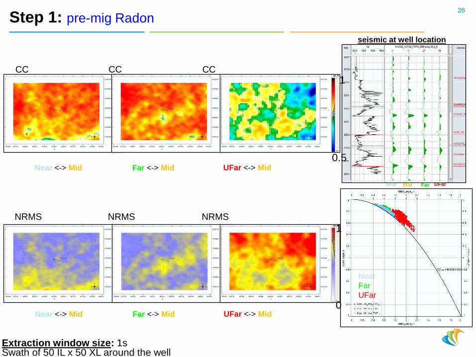
Step 1: pre-mig Radon26
seismic at well location
Near Far UFar
Near <-> Mid Far <-> Mid UFar <-> Mid
CC CC CC
Near <-> Mid Far <-> Mid UFar <-> Mid
Near
Far
UFar
1
0
1
0.5
Extraction window size: 1sSwath of 50 IL x 50 XL around the well
NRMSNRMSNRMS

27
CC CC CC
Near
Far
UFar
1
0
1
0.5
Extraction window size: 1sSwath of 50 IL x 50 XL around the well
seismic at well location
MidNear Far UFar
Near <-> Mid Far <-> Mid UFar <-> Mid
Near <-> Mid Far <-> Mid UFar <-> Mid
Step 2: 5D signal enhancement
NRMSNRMSNRMS

28
Near
Far
UFar
CC CC CC
1
0
1
0.5
Extraction window size: 1sSwath of 50 IL x 50 XL around the well
seismic at well location
MidNear Far UFar
Near <-> Mid Far <-> Mid UFar <-> Mid
Near <-> Mid Far <-> Mid UFar <-> Mid
Step 3: F-XY denoise
NRMSNRMSNRMS
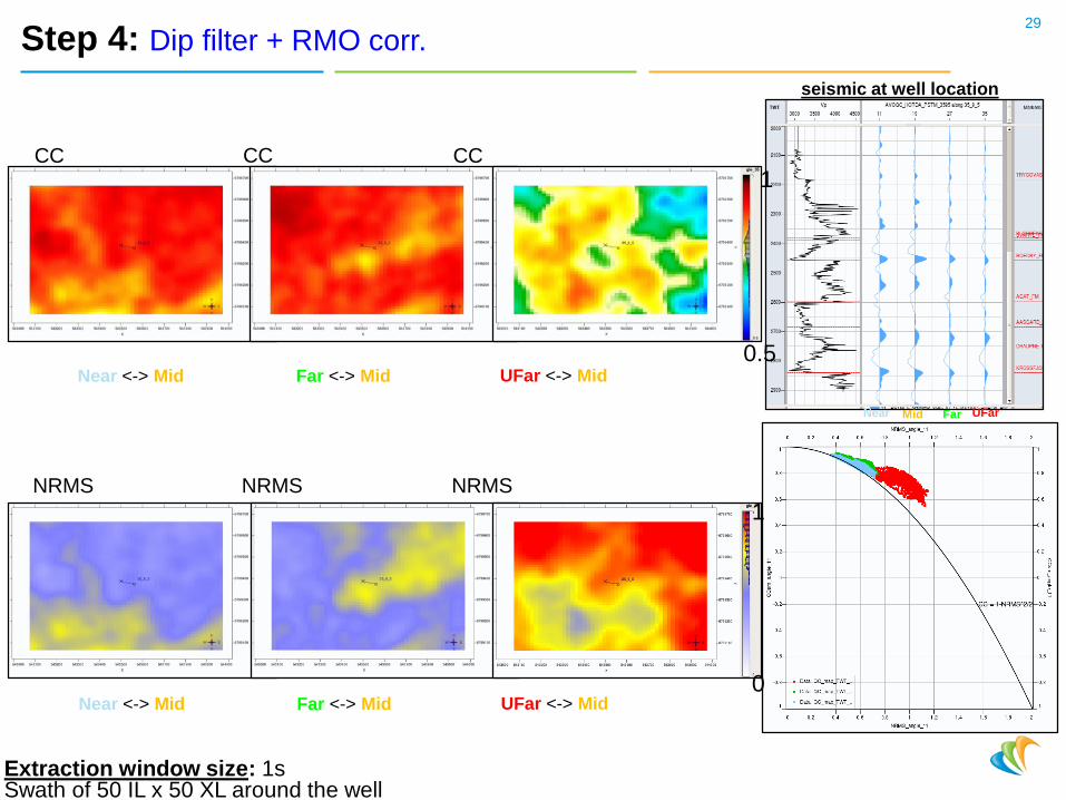
29
Near
Far
UFar
NRMSNRMSNRMS
CC CC CC
1
0
1
0.5
Extraction window size: 1sSwath of 50 IL x 50 XL around the well
seismic at well location
MidNear Far UFar
Near <-> Mid Far <-> Mid UFar <-> Mid
Near <-> Mid Far <-> Mid UFar <-> Mid
Step 4: Dip filter + RMO corr.

Observations/Conclusions:
Increased repeatability between angle stacks;
30

Advanced seismic QCs results proposed in this presentation:31
Seismic gathers
Angle stacks creationNear, Mid, Far, Ufar,…
Wells with elastic logs (P-sonic, S-sonic, Density)
Within a vintage With an AVO model
AVO synthetic model
Well based QC
3D SEI at the well
location
Seismic based QC

Objective and key observations to be done during those QCs:
Is the Zoeppritz compliancy of the seismic data improving during the processing > are less
residuals observed between an AVO model and the real seismic data?
32

Comparison between angle stacks and synthetic angle stacks generated from an
AVO analysis.
33
Seismic
angle stacks
AVO Synthetic
angle stacksResiduals,
CC, NRMS
AVO analysis
using a robust
2 terms AVO fit
Methodology:

34Step 1: pre-mig Radon / «Real» angle stacks
Near Mid Far Ufar

35
Near Mid Far Ufar
Step 1: pre-mig Radon / Synthetic angle stacks

36
Near Mid Far Ufar
Step 4: Dip filter + RMO corr. / «Real» angle stacks

37
Near Mid Far Ufar
Step 4: Dip filter + RMO corr. / Synthetic angle stacks
38
Near Mid Far Ufar
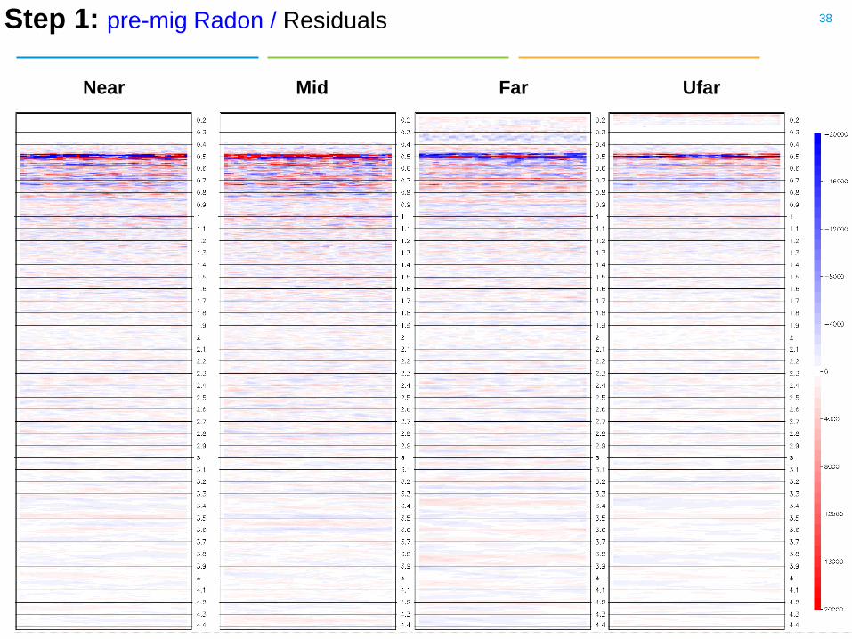
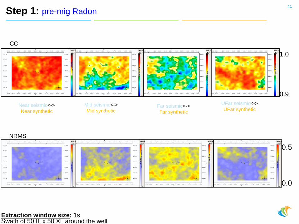
Step 1: pre-mig Radon / Residuals
39
Near Mid Far Ufar
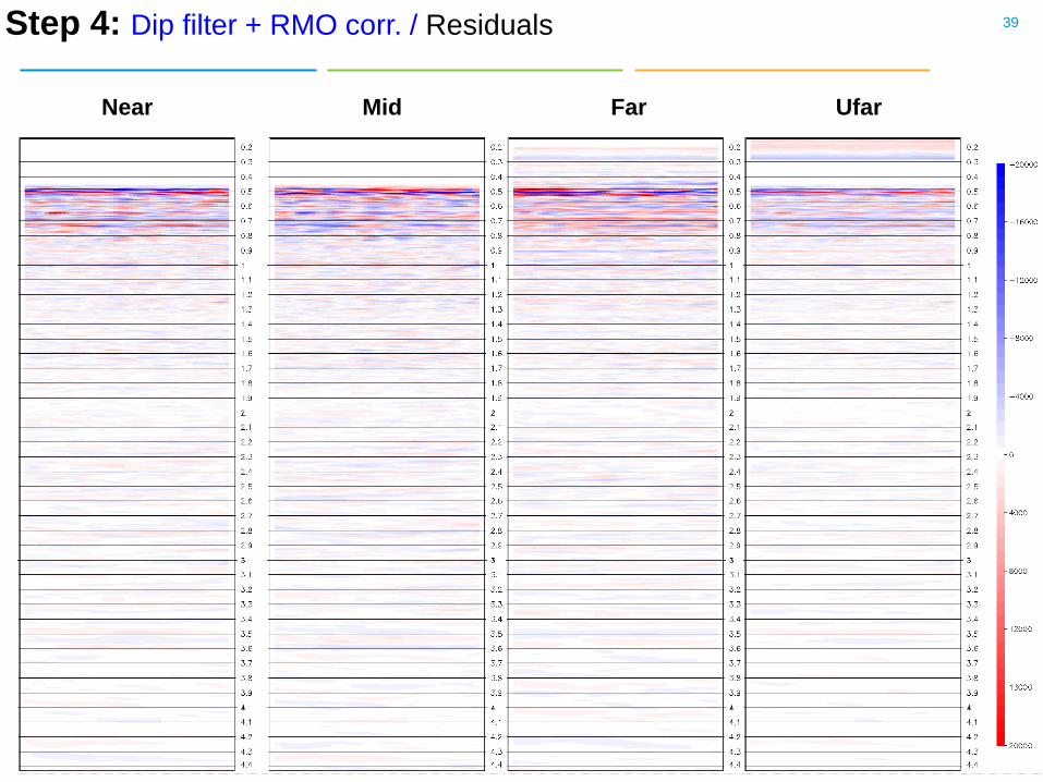
Step 4: Dip filter + RMO corr. / Residuals

MidInput seismic
AVO synthetic
Residuals
Amplitude spectra of the residuals:40
Near Mid
Far UFar
Red: early
Yellow: late
41
Near seismic<->
Near synthetic
Mid seismic<->
Mid syntheticFar seismic<->
Far synthetic
CC
UFar seismic<->
UFar synthetic
1.0
0.9
0.5
0.0
Extraction window size: 1sSwath of 50 IL x 50 XL around the well
Step 1: pre-mig Radon
NRMS

42
Near seismic<->
Near synthetic
Mid seismic<->
Mid syntheticFar seismic<->
Far synthetic
CC
UFar seismic<->
UFar synthetic
1.0
0.9
0.5
0.0
Extraction window size: 1sSwath of 50 IL x 50 XL around the well
Step 2: 5D signal enhancement
NRMS

43
Near seismic<->
Near synthetic
Mid seismic<->
Mid syntheticFar seismic<->
Far synthetic
CC
UFar seismic<->
UFar synthetic
1.0
0.9
0.5
0.0
Extraction window size: 1sSwath of 50 IL x 50 XL around the well
Step 3: F-XY denoise
NRMS

44
NRMS
Near seismic<->
Near synthetic
Mid seismic<->
Mid syntheticFar seismic<->
Far synthetic
CC
UFar seismic<->
UFar synthetic
1.0
0.9
0.5
0.0
Extraction window size: 1sSwath of 50 IL x 50 XL around the well
Step 4: Dip filter + RMO corr.
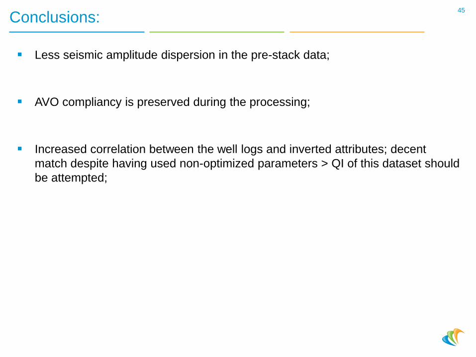
Conclusions:
Less seismic amplitude dispersion in the pre-stack data;
AVO compliancy is preserved during the processing;
Increased correlation between the well logs and inverted attributes; decent
match despite having used non-optimized parameters > QI of this dataset should
be attempted;
45

Recommendations:
These QCs should become standard in any seismic processing project;
QCs should not be restricted to a few traces at arbitrarily chosen well locations.
46


![[Castagna J.P.] AVO Course Notes, Part 3. Poor AVO](https://img.dokumen.tips/doc/110x75/563db964550346aa9a9ce6c7/castagna-jp-avo-course-notes-part-3-poor-avo.jpg)


