Embed Size (px)
Citation preview

CUSTOMERSUPPORT
INFORMATION
Order toll-free in the U.S. 24 hours, 7 A.M. Monday to midnight Friday: 877-877-BBOXFREE technical support, 24 hours a day, 7 days a week: Call 724-746-5500 or fax 724-746-0746Mail order: Black Box Corporation, 1000 Park Drive, Lawrence, PA 15055-1018Web site: www.blackbox.com • E-mail: [email protected]
SEPTEMBER 1993AC400AAC401A
Real Color 16 LCD Projection PanelMonochrome 16 LCD Projection Panel

1
REAL COLOR AND MONOCHROME 16 LCD PROJECTION PANELS
FEDERAL COMMUNICATIONS COMMISSIONRADIO FREQUENCY INTERFERENCE STATEMENT
This equipment generates, uses, and can radiate radio frequency energy and if not installed and used properly, that is, in strict accordance with themanufacturer’s instructions, may cause interference to radio communication.It has been tested and found to comply with the limits for a Class Acomputing device in accordance with the specifications in Subpart J ofPart 15 of FCC rules, which are designed to provide reasonable protectionagainst such interference when the equipment is operated in a commercialenvironment. Operation of this equipment in a residential area is likely tocause interference, in which case the user at his own expense will be requiredto take whatever measures may be necessary to correct the interference.
Changes or modifications not expressly approved by the party responsible for compliance could void the user’s authority to operate the equipment.
This digital apparatus does not exceed the Class A limits for Radio noise emission fromdigital apparatus set out in the Radio Interference Regulation of Industry Canada.
Le présent appareil numérique n’émet pas de bruits radioélectriques dépassant les limitesapplicables aux appareils numériques de la classe A/ prescrites dans le Règlement sur lebrouillage radioélectrique édicté par Industrie Canada.

2
REAL COLOR AND MONOCHROME 16 LCD PROJECTION PANELS
TRADEMARKS
UL® is a registered trademark of Underwriters Laboratories Incorporated.
Macintosh® and Apple® are registered trademarks of Apple Computer, Inc.
IBM® and PS/2® are registered trademarks of IBM Corporation.
MS-DOS® is a registered trademark of Microsoft Corporation.
Compaq® is a registered trademark of Compaq Computer Corporation.
Dell® is a registered trademark of Dell Corporation.
Epson® is a registered trademark of Seiko Epson C orporation.
Sharp® is a registered trademark of Sharp Corporation.
Toshiba® is a registered trademark of Toshiba Corporation.
Zenith® is a registered trademark of Zenith Electronics Corporation.
Any other trademarks mentioned in this manual are acknowledged to be the property of the trademark owners.

3
REAL COLOR AND MONOCHROME 16 LCD PROJECTION PANELS
ContentsChapter Page
1. Specifications.................................................................................................. 4
2. Introduction ................................................................................................... 52.1 Description ............................................................................................ 52.2 Shipping Container Contents .............................................................. 62.3 General Guidelines ............................................................................... 7
3. Installation...................................................................................................... 83.1 Setup Instructions................................................................................. 83.2 Connecting the Projection Panel to a Desktop Computer ................123.3 Connecting the Projection Panel to an IBM PC
Compatible Laptop Computer ............................................................133.4 Connecting the Projection Panel to a Macintosh
Series Computer ...................................................................................14
4. Operation .......................................................................................................154.1 Adjusting the Projection Panel ............................................................154.2 Non-Shift Control Button Functions ...................................................174.3 Shift-Activated Control Button Functions ...........................................194.4 Using the Control Buttons to Make Adjustments...............................224.5 User Menu.............................................................................................234.6 Moving Through the User Menu.........................................................244.7 Adjusting a Menu Option ....................................................................24
5. Maintenance and Troubleshooting ..............................................................285.1 Cleaning the Display Surface ...............................................................285.2 Cleaning the Projection Panel Filter ...................................................285.3 Troubleshooting Guide ........................................................................29
Appendix A: Working With Colors (AC400A only).........................................32
Appendix B: Interface Requirements ...............................................................33B.1 Power Connector Polarity ....................................................................34B.2 Screen Area...........................................................................................34
Appendix C: Special Guidelines for IBM and Compatibles ............................36C.1 IBM Computers with Two Display Cards ............................................36C.2 Instructions for Activating Portables and Laptops .............................37

4
REAL COLOR AND MONOCHROME 16 LCD PROJECTION PANELS
1. SpecificationsResolution — 640 x 480
Power — UL® approved 12 VDC, 1.5A power supply
Size — 15.3"H x 13.1"W x 2.6"D (38.9 x 33.3 x 6.6 cm)
Weight — 5.9 lb. (2.7 kg)

5
CHAPTER 2: Introduction
2. Introduction
Fig. 2-1. The Projection Panel on an Overhead Projector.
2.1 DescriptionFor remarkably impressivepresentations, use the Real Color or Monochrome 16 LCD ProjectionPanel. The Panel, which projects 16 real colors or 16 shades of grey,delivers the computer compatibilityand ease of use you never thoughtpossible in an LCD projection panel.Fig. 2-1 illustrates the Panel coupledwith an overhead projector.

6
REAL COLOR AND MONOCHROME 16 LCD PROJECTION PANELS
The Projection Panel is easy touse. Simply connect the Panel to acomputer graphics card and placethe unit onto an ordinary overheadprojector. The data and graphicsnormally displayed on the computermonitor will be projected in imagesthat you can easily see in typicalroom lighting. The Projection Panelhas a temperature-regulating fan,which works with the heat-producingoverhead projector, to hold theliquid crystal display (LCD) to theoptimum temperature. You can usethe Projection Panel on a wide rangeof overhead projectors rated up to650 watts.
The Projection Panel, with a640x480 pixel display, is compatiblewith the Macintosh® series andMacintosh II series; with Apple® IIGSRGB; with IBM® PC and compatiblesin CGA, EGA, and VGA modes, andwith the IBM PS/2® with VGA or CGA.
2.2 Shipping Container ContentsThe components shown in Fig. 2-2are included with the ProjectionPanel.
1. Projection Panel
2. This User Manual
3. 12-volt power supply
4, 6. 15-pin Mac II, LC, Apple IIgs
5. 15-pin VGA
If any pieces are missing when you first open the box, contact BlackBox immediately.
1
2 3
6
5
4
Fig. 2-2. The Projection Panel and Included Components.

7
CHAPTER 2: Introduction
2.3 General GuidelinesFollow these guidelines when youuse the Projection Panel.
• Be sure the Projection Panel is on whenever the overheadprojector is turned on.
CAUTIONIf the Projection Panel is noton when it is on top of anoperating overhead pro-jector, the Panel couldsustain damage.
• Do not use the Projection Panelfor extended periods of time onan overhead projector known fordiscoloring or melting standardtransparencies.
• When you use the Panel with ahigh-wattage projector or if younotice extreme discoloration ofthe Panel, periodically removethe Panel from the overheadprojector to allow it to cool.
• The bottom of the Panel canbecome very hot to the touchafter use. Be careful to let thePanel cool before lifting it.
• Do not block the ProjectionPanel fan or free air movementunder and around the Panel.Air flows from back to front.
• Turn the overhead projector offand unplug the Projection Panelwhen not in use.
• Handle the Projection Panel asyou would anything made ofglass. Be especially careful not to drop it.
• You can easily clean theProjection Panel with standardnon-abrasive glass cleaner. Applythe cleaner to the cleaning clothand then wipe the glass surfacelightly. Do not use excessiveamounts of liquid or pressure onthe top or bottom optical panels.
• Avoid scratching the ProjectionPanel surface with sharp metalobjects. The top surface is madeof glass or a scratch-resistanthardened polymer. If you needto clean the surface, use normalglass-cleaner solution. Do notuse abrasive cleaners, solvents, or other harsh chemicals.
• Avoid leaving the ProjectionPanel in direct sunlight orextreme cold for extendedperiods of time.

8
REAL COLOR AND MONOCHROME 16 LCD PROJECTION PANEL
3. Installation
Fig. 3-1. Projection Panel and Overhead Projector, Showing Cable Connections.
3.1 Setup InstructionsThis chapter explains theconnections you must make betweenthe three pieces of equipment youwill be using—the Projection Panel,your computer, and monitor. Besure to follow the instructions foryour type of computer.

9
CHAPTER 3: Installation
3.1.1 CABLES
Three cables are supplied with theProjection Panel:
1. A Macintosh II/MacintoshLC/Apple IIGS loop-throughcable
2. A VGA/MCGA loop-throughcable
3. A loop-through cable for EGA,CGA, or Macintosh video
Fig. 3-2. Cables.
15-pin VGA 9-pin VGA15-pin MacII
The cables that come with yourProjection Panel are used to connectthe computer’s video port to theProjection Panel and the monitor.Each of the three cables has a 26-pinconnector for the Projection Panel,a connector matching the video cardand a connector for the monitor.The Projection Panel receives thecomputer’s signals, amplifies thesignals, and sends them out to themonitor.
10
REAL COLOR AND MONOCHROME 16 LCD PROJECTION PANEL
10
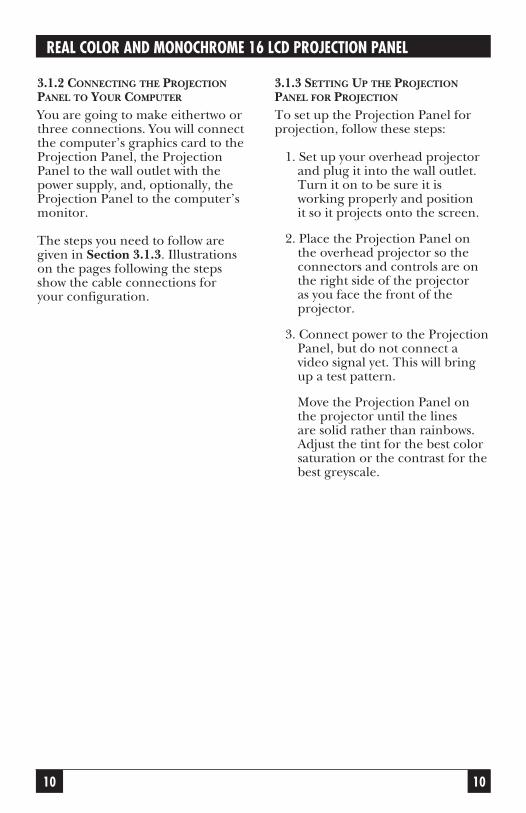
3.1.2 CONNECTING THE PROJECTIONPANEL TO YOUR COMPUTER
You are going to make eithertwo orthree connections. You will connectthe computer’s graphics card to theProjection Panel, the ProjectionPanel to the wall outlet with thepower supply, and, optionally, theProjection Panel to the computer’smonitor.
The steps you need to follow aregiven in Section 3.1.3. Illustrationson the pages following the stepsshow the cable connections for your configuration.
3.1.3 SETTING UP THE PROJECTIONPANEL FOR PROJECTION
To set up the Projection Panel forprojection, follow these steps:
1. Set up your overhead projectorand plug it into the wall outlet.Turn it on to be sure it isworking properly and position it so it projects onto the screen.
2. Place the Projection Panel onthe overhead projector so theconnectors and controls are onthe right side of the projector as you face the front of theprojector.
3. Connect power to the ProjectionPanel, but do not connect avideo signal yet. This will bringup a test pattern.
Move the Projection Panel onthe projector until the lines are solid rather than rainbows.Adjust the tint for the best colorsaturation or the contrast for thebest greyscale.

11
CHAPTER 3: Installation
11
Fig. 3-3. Selecting the Proper “Y” Cable for Your Computer.
6. Unplug the computer monitorcable from the graphics card.Plug the monitor to the shortend (marked Monitor) of theProjection Panel cable to thecomputer monitor.
7. Plug the long end of theProjection Panel cable (markedfor the appropriate computer)to the computer’s video port.
8. Tighten the thumb screws onthe cable connectors to ensureproper grounding.
Refer to Appendix A for additionalimportant information on how toproperly place a Projection Panel on an overhead projector.
4. Follow the instructions in thistable to select the proper “Y”cable for your computer:5.Connect the 26-pin end (markedLCD) of the “Y” cable to theProjection Panel.
NOTESkip step 6 if you areconnecting to a classic-styleMacintosh.
Computer Cable Looks like
IBM or compatible 15-pin
with VGA Graphics Card
or IBM PS/2 with built-in
VGA or MCGA Graphics
IBM or Compatible 9-pin
with EGA or CGA
Graphics Card or
Classic Style Macintosh
Macintosh II Series or 15-pin
Macintsoh LC, Apple IIGS

12
REAL COLOR AND MONOCHROME 16 LCD PROJECTION PANEL
3.2 Connecting the Projection Panelto a Desktop ComputerFigure 3-4 shows how to connect theProjection Panel to typical desktopcomputers, which include CGA,EGA, VGA, Macintosh II, andMacintosh LC setups.
All cables are labeled (forexample, LCD, Monitor, VGA, etc.)to indicate where they connect.
Fig. 3-4. Desktop Computer with a Y-Cable.

13
CHAPTER 3: Installation
3.3 Connecting the Projection Panelto an IBM PC Compatible LaptopComputerFigure 3-5 shows a typical laptopinstallation.
Fig. 3-5. Typical Laptop Installation.
When the external port isactivated, many laptop computersautomatically turn off their internaldisplay. For more information, seeAppendix C or your computermanual for typical laptop commands.The short end of the loop-throughcable is not connected in thisinstallation.
CAUTIONThe Projection Panel is notcompatible with theMacintosh laptop. Do notattempt to connect theProjection Panel to aMacintosh laptop. Seriousdamage to the computer orProjection Panel couldresult.

14
REAL COLOR AND MONOCHROME 16 LCD PROJECTION PANEL
3.4 Connecting the Projection Panelto a Macintosh Series ComputerFigure 3-6 shows how to connect theProjection Panel to a Macintoshseries computer.
Fig. 3-6. Macintosh Series Computer.
Because classic-style Macintoshcomputers do not have a videoconnector, you must install aninternal adapter. The Macintosh128, 512, and Plus require an A10adapter. The SE and SE/30 requirean A20. The Macintosh Classicrequires an A21. Call your dealer formore information. Note that theshort end of the loop-through cableis not connected in this installation.
NOTEBecause the SE and Plusmodels of the Macintoshcomputer only display inmonochrome at a resolutionof 512x342 pixels, a RealColor 16 LCD ProjectionPanel connected to one ofthese models will onlyproject monochrome and willnot fill the entire ProjectionPanel screen.

15
CHAPTER 4: Operation
4. OperationSome of the buttons are auto-
repeat buttons; that is, pressing andholding these buttons causes themto constantly send instructions.Other buttons toggle through afixed number of settings and requireyou to press the button each time totrigger the next setting.
4.1 Adjusting the Projection PanelAt this point, bring up the softwareyou want to project. You should beprojecting an image on the screen.This section will show you how toadjust the Projection Panel to getclear, crisp images. You can adjustthe Projection Panel using the 10-function keypad.
4.1.1 CONTROL BUTTON FUNCTIONS
There are ten operating controlbuttons on the Projection Panel. ASHIFT button, located in the lowerleft corner, allows several of thesebuttons to have a dual function(non-shift functions are printed in gray, shift functions are in blue). Six of the buttons are combinedas dual-action switches.

16
REAL COLOR AND MONOCHROME 16 LCD PROJECTION PANELS
Fig. 4-1. Projection Panel Keypad.
Table 4-1. Non-Shift and Shift Keys.
NON-SHIFT SHIFTKEYS KEYS
Tint (up/down) Level (up/down)
Contrast (up/down)
Sync+ Sync-
Position (up/down)
Position (left/right) Menu (toggle)
Clear Reset
Reverse Palette
resetcleartint
levelposition
palettereverse
sync-sync+
menupositionshift

17
CHAPTER 4: Operation
4.2 Non-Shift Control ButtonsTo activate one of the non-shiftbuttons (printed in grey) on theoperating control panel, just pressthe button.
4.2.1 TINT (TRUE COLOR)Press the Tint key to adjust the color.The Tint Up key adds red and greento the image. Blue levels areaffected by a mix of red and green.
Fig. 4-3. Contrast (Monochrome).
4.2.3 SYNC+The Projection Panel has beencalibrated to automatically matchsignals sent by specific computersystems (CGA, EGA, VGA, PS/2, andMacintosh series). However, eachindividual video card varies slightlyfrom others.
tintlevel
Fig. 4-2. Tint (True Color).
4.2. CONTRAST (MONOICHROME)The Contrast key allows the userto adjust the brightness of thedisplayed image for optimumviewing. Contrast Up increases theperceived brightness of all shadesequally, while Contrast Downdecreases the brightness of allshades equally. There are 64contrast levels available.
contrastlevel
sync+sync-
Fig. 4-4. Sync+.

18
REAL COLOR AND MONOCHROME 16 LCD PROJECTION PANELS
Projected characters or graphicsmay appear to shimmer because ofdifferences in signal outputs of somecomputers. Press the Sync+ buttonuntil projected characters “lock” intoposition and shimmering iseliminated.
Each time Sync+ is pushed, it fine-tunes the Projection Panel to matchsignals from the graphics system.Sync+ continuously cycles forwardthrough all 16 positions (press sync-to cycle back to a good syncposition).
4.2.4 POSITION, UP OR DOWN
Press the up or down positionbutton to center the image verticallyon the screen. This button auto-repeats.
4.2.5 POSITION, LEFT OR RIGHT
Press the up or down positionbutton to center the imagehorizontally on the screen. Thisbutton auto-repeats.
position
Fig. 4-5. Position, Up or Down.
positionmenu
Fig. 4-6. Position, Left or Right.
4.2.6 CLEAR
Pressing the Clear button cleans anyunwanted random patterns that mayhave appeared on the screen outsidethe image area. In some cases,positioning the image will leave atrail of data. Use the Clear button to remove this unwanted data.
You may also use this control toblank the screen by clearing the testpattern to all black or all yellow.Disconnect the video signal to bringup the test pattern and press Clear.Background color depends on thestate of Reverse. Pressing Clearagain will restore the screen.

19
CHAPTER 4: Operation
Fig. 4-7. Clear.
4.2. REVERSE
If you wish to reverse the way you seean image, light letters on a darkbackground or dark letters on a lightbackground, press the Reversebutton. Pressing it again causes thedisplay to return to the originalimage. All colors will be switchedwith their complements.See Appendix A for more infor-mation on working with colors.
Fig. 4-8. Reverse.
4.3 Shift-Activated Control ButtonFunctionsThe functions shown on theoperating control panel in blueletters are activated when the Shiftbutton is held down while acommand button is pushed.
clearreset
reversepalette

20
REAL COLOR AND MONOCHROME 16 LCD PROJECTION PANELS
4.3.1 SYNC-Each time Sync- is pushed, it finetunes the Projection Panel to matchsignals from the graphics system.Sync- continuously cycles backwardthrough all 16 positions.
4.3.2 RESET
The master reset function, holdingdown the Shift button and pressingReset, returns the display settings(Position, Sync, Palette, Reverse, andLevel) for the video mode beingdisplayed to factory defaults.
The Reset function does not affectTracking, Text Mode, Text Slice,Tint, Contrast, or EGA mode unlessthe menu is showing on the screen.If the menu is displayed, all displaysettings and menu items, includingthe color bars, are reset to factory-default values.
Fig. 4-9. Holding Down Shift and Pushing a Command Button.
shift sync+sync-
Fig. 4-10. Sync-.

21
CHAPTER 4: Operation
Fig. 4-11. Reset.
4.3.3 PALETTE
Pressing the Palette button selectsthe displayed color palette size. Thisbutton allows you to switch between8-color and 16-color displays on theReal Color Panel and select one ofseven, color-to-greyshade mappingson the Monochrome panel.
4.3.4 LEVEL UP AND LEVEL DOWN
The Level button adjusts the colormapping to compensate forcomputer-to-computer differences.Just as colors look different ondifferent monitors, there will alwaysbe some color differences betweenthe monitor and the ProjectionPanel. If the color match betweenthe monitor and the ProjectionPanel is not satisfactory, the level canbe adjusted to change the mapping.It is important, however, to ensurethat the Tint or Contrast is setcorrectly prior to adjusting the level.
Level Up or Level Down increasesyour flexibility by allowing you tochoose which tones ofcolor/greyscale will be projected.
Pressing Level Up increases thelimits of the range of tone which willbe depicted by that color. PressingLevel Down will cause a smallerband of tone to be depicted as agiven color. There are 64 steps. Thelevel controls operate only on analogvideo signals such as those fromVGA, MCGA, or Macintosh II displaysystems.
shift clearreset
shift reversepalette
Fig. 4-12. Palette.

22
REAL COLOR AND MONOCHROME 16 LCD PROJECTION PANELS
Fig. 4-13. Level Up and LevelDown.
4.3.5 MENU
Pressing the Menu control displaysthe User Menu, which allows you toadjust the initial color balance andtracking, change the text mode andlanguage, and flip the projectionimage. The User Menu also providesinformation about the video input.After you display the User Menu, usethe Position (< >) control buttonsto move within and between menuoptions, and the Position ( ^ or v )to change an option.
For information about the UserMenu, see the section later in thischapter.
Shift-Menu (either button) movesyou in or out of menu mode.
Fig. 4-14. Menu.
4.4 Using the Control Buttons toMake AdjustmentsNow that you have reviewed thefunctions of each of the controlbuttons, here is the order in whichyou use them to achieve the bestpossible projected image.
1. Press the Tint or Contrastbuttons up or down to changethe color of your image or textfor the best viewing. Tint orcontrast is easiest to adjust withan image that contains largeareas of different color orgreyscale.
2. Move the image on the screenwith the Position Up, Down,Left, and Right buttons until it is centered.
3. Focus the overhead projectoruntil the image is crisp andclear.
shifttint
level
shift positionmenu

23
CHAPTER 4: Operation
NOTEThe Projection Panel mustbe placed correctly on theoverhead projector. Incorrectplacement may cause theProjection Panel to projectblurry or mis-convergedimages. For more infor-mation, see Appendix A.
4. Press Sync until the image islocked in as a solid image withno shimmer or movement. Thisbutton toggles through thepresent settings to the specificcomputer graphics type. PressSync until you achieve the bestimage.
5. For VGA, MCGA, and MacintoshII, you may need to hold downShift and press Level Up orLevel Down to choose the bestcolor matching. For best resultswhen adjusting the level, displayan image that has a wide rangeof colors.
For VGA text display, you mayneed to adjust the Text Mode ifthe text characters are jagged orshimmering.
6. If your computer is one of thestandard supported systems,your image should be fullyadjusted at this point. However,if your computer is any othertype, you may see evenly spacedfuzzy vertical lines, or text mayappear to be too wide or toonarrow for the screen. Tocorrect this problem, go to theUser Menu (press the Menucontrol button) and adjust thetracking.
7. You may want to press Reverseto select either light characterson a dark background or darkcharacters on a lightbackground. Use the settingwhich best suits your graphics ortext.
8. To restore factory-set defaultvalues, hold down Shift andpress Reset while the menu isbeing displayed.
4.5 User MenuPressing the Menu control buttondisplays the User Menu on yourcomputer’s monitor. The UserMenu allows you to change the colorbalance, adjust the tracking, andcontrol how information isdisplayed.

24
REAL COLOR AND MONOCHROME 16 LCD PROJECTION PANELS
4.6 Moving Through the User MenuAfter you display the User Menu, usethe Position control buttons (leftand right) to move within andbetween option columns.
These keys are auto-repeatbuttons; that is, pressing andholding these buttons causes themto constantly send instructions.
Tint/.Contrast and Level buttonsare still active when in Menu Mode.
4.7 Adjusting a Menu OptionUse the Position Up and Downcontrol buttons to adjust menuoptions. These keys auto-repeat.Pressing Shift RESET when themenu is showing resets all menuitems, including the coloradjustments, to factory-defaultvalues.
4.7.1 COLOR BALANCE (TRUE COLORONLY)Adjust the Tint control to get thebest colors. Black and white willalways have a reddish tint. If thecolors still need adjustment, displaythe menu by pressing Shift-Menu. Ifyou press Shift-Reset when the menuis displayed, the color balance will bereset to its factory default values.Resetting to default and slightlyadjusting the Tint control may beenough to improve the colors.
NO VIDEO
TRACK 800
HORZ 15.3
VERT +60
MODE 15
LANGUAGE
REAR PROJECT
TEXT SLICE
TEXT MODE
EGA 64
RED GRN LevelTRACKENGLISH
OFF
1
ON
OFF
Fig. 4-15. Projection Panel Menu.

25
CHAPTER 4: Operation
If the colors still need adjustment,follow these steps and use the redand green adjustments to fine-tunethe panel:
1. Move the green bar down untilyou have a rich red and a solidblack.
2. Move the red bar down until youhave a rich, true green. If cyanturns green, the green bar turnsbrown, and the white turnsmagenta, you have moved thebar too far down.
3. If your white is magenta-tinted,drop the red bar down a fewsteps until it is white, but not sofar that the black turns red.White and black, however, arealways going to be slightlyreddish.
4.7.2 EGA 64 For the True Color Panel, EGA 64may affect the color brown on someEGA systems and some VGA systemswhen in EGA mode. If your brown isdisplaying as light red, turn on theEGA 64 setting.
For the Monochrome Panel, EGA64 may allow you to get all 16 shadesof grey instead of 15 shades.
Default value is OFF.
4.7.3 TRACKING
The Tracking adjustment bar allowsyou to match the Projection Panel’sinternal clock to the differentcomputer graphics signals. Usingtracking allows the Projection Panelto project crisp images from a rangeof computer graphics systems. Thereare 64 tracking levels.
You need to adjust the tracking if the display shows evenly spaced,fuzzy vertical lines, or if theprojected image is too wide or toonarrow for the screen.Move the tracking bar down (lowernumbers) to make the image looknarrower. Move the tracking bar up(higher numbers) to make theimage look wider. The default Trackvalue is shown with the VideoInformation. As you move theTracking adjustment bar up ordown, the Track value changes.Move the Tracking adjustment barup or down until the fuzzy linesmove apart on the screen ordisappear, or the text fits the screen.The ideal is to have no bars visibleand all the projected text or graphicson the screen.

26
REAL COLOR AND MONOCHROME 16 LCD PROJECTION PANELS
4.7.4 VIDEO/NO VIDEO
The Video column providesinformation about the current videoinput. If video is not present, theUser Menu displays “No Video,” withno Horizontal or Mode informationand the test pattern or blank screenvisible in the image area.
The Video information columnshows the tracking setting (describedpreviously), the horizontal syncfrequency and polarity (HORZ), thevertical sync frequency and polarity(VERT), and the video modenumber (MODE).
These values (except for Track)are for informational purposes andcannot be adjusted. If you areexperiencing problems, be sure towrite down these values beforecalling Technical Support.
4.7.5 LANGUAGE
Menus can be displayed in eitherEnglish, French, German, Italian, orSpanish. The User Menu allows youto choose the language. The defaultis English.
4.7.6 REAR PROJECTION
Select ON to flip the image from leftto right for rear projection screens.The default is OFF. Rear projectionallows you to use a standardoverhead projector without complexmirror setups for rear projection.
Fig. 4-16. Tracking.

27
CHAPTER 4: Operation
Fig. 4-17. Rear Projection.
Selecting ON for the Text Modelocks VGA text to solid pixels (noshimmering). CGA graphics,however, may be compressed. Unlessyou regularly project CGA graphicswith the Projection Panel, text modeshould be set to ON.
Text Mode works only when text is present. For example, this modeworks in VGA text but not in VGAgraphics.
You are now ready to begin apresentation.
Now that the Projection Panel isproperly connected and you haveadjusted the image on the screen,you are ready to begin projectingyour computer data and graphics.
The projected images will be livefrom your computer and change asyou change the computer data.
4.7.7 TEXT SLICE
Text Slice allows you to adjust VGAtext characters to look their best.The Projection Panel discards one of seven pixels to adjust characters.Text Slice allows you to choosewhich of the seven pixels you wantthe Projection Panel to discard. TextSlice is ON for only 720 text mode(VGA text). Text Slice has no effecton characters when Text Mode isOFF. Adjust the Text Slice until yourcharacters are solid and fullyformed.
4.7.8 TEXT MODE
The Projection Panel screen area is640 pixels wide. Text that extendsbeyond 640 pixels may be eithercompressed or truncated. When text(or graphics) is compressed, it istightly spaced to fit the displayscreen. Truncated text (or graphics)is not respaced to fit the display;rather, anything beyond the rightedge of the screen display is notshown.

28
REAL COLOR AND MONOCHROME 16 LCD PROJECTION PANELS
5. Maintenance and Troubleshooting2. If the surface needs cleaning,
you can use any normal non-abrasive glass cleaner on it.Apply the cleaner to a cleaningcloth and then wipe the surfacelightly. Do not use excessiveamounts of liquid. Do not useabrasive cleaners, solvents, orother harsh chemicals.
5.2 Cleaning the Projection PanelFilterThe filter, which is located at thefront of the Projection Panel,catches dust particles before they get into the Projection Panel. Youneed to routinely clean the filter. Toclean the filter, follow these steps:
1. Unsnap the fan cover.
The information in this chapter is a guide to the cleaning andmaintenance of your ProjectionPanel, as well as to locating andsolving possible problems.
5.1 Cleaning the Display Surface1. Handle the Projection Panel
as you would anything made ofglass. Be especially careful not to drop it.
The hardened polymer surfaceof the Real Color 16 LCDProjection Panel (AC400A) isdesigned to be scratch and dentresistant. However, you shouldavoid scratching it with sharpmetal objects. The Monochrome16 LCD Projection Panel(AC401A) surface is made ofglass, and you should follow theinstructions in step 2.

29
CHAPTER 5: Maintenance and Troubleshooting
2. Gently remove the filter andclean it by washing it in gentlesoap. Be sure to let the filter drycompletely before re-inserting itin the Projection Panel.
The frequency with which youwill need to clean the filterdepends on how often you use the Panel. Typically, you will need to clean the filterapproximately once every three to six months or when the Projection Panel overheatsfrom a clogged filter.
5.3 Troubleshooting GuideBefore calling Technical Support for assistance, attempt to solve theproblem by checking thistroubleshooting guide.
Problem: Nothing on screen.
Possible Causes and Solutions:
• You may not have any power or you may be using the wrongpower supply. Check to see thatthe proper Projection Panelpower supply is being used with the Projection Panel.
Filter
Fig. 5-1. The Projection Panel Filter.

30
REAL COLOR AND MONOCHROME 16 LCD PROJECTION PANELS
• The power supply may not beplugged into a live AC outlet.Check to ensure that the powersupply is connected to theProjection Panel and to a live AC wall outlet.
• Your power supply may beplugged into a power strip that is not turned on.
• Your overhead projector may notbe set up correctly. Check to see that the projector is on andplugged in properly. Also checkthe bulb, and make sure theoverhead deflector is correctlypositioned.
• You Projection Panel may not beadjusted properly. Also, checkand adjust the contrast and levelcontrol settings.
Problem: Color or VGA text notbeing projected.
Possible Causes and Solutions:
• Your level control may need to be adjusted. Adjust theProjection Panel level control upor down until the text is visible.
• Your software may be displayingcolors that are too similar. Setyour software to increase thedifference between displayedcolors.
Problem: Image not centered onthe screen.
Possible Causes and Solutions:
• Adjust position to center imageon screen.
Problem: Only the test pattern isbeing displayed.
Possible Causes and Solutions:
• Your Projection Panel videocables may not be connectedcorrectly. Check to see that thecable is connected to the videoport on the computer’s graphicscard.
• Your computer graphics systemmay not be set up correctly.Check the following: yourcomputer’s color graphics cardis turned on; your computer hasa compatible graphics card; andthe computer’s external videocard has been turned on.
Problem: Image is too wide ornarrow for screen.
Possible Causes and Solutions:
• You may need to adjust thetracking to reduce or enlargethe projected image.
• Check to see that your computeris using a compatible graphicscard.
• You may be using a high-resolution display card. Make sure your computer iscompatible. Change theresolution if you can.

31
CHAPTER 5: Maintenance and Troubleshooting
Problem: Image is out of focus.
Possible Causes and Solutions:
• Overhead is not adjustedcorrectly. Adjust overhead untilimage is in focus.
• The surface of the ProjectionPanel or overhead projector mayneed cleaning.
Problem: Vertical lines or bleeding.
Possible Causes and Solutions:
• Adjust tint to minimize verticallines or bleeding from aroundprojected boxes or borders.
Problem: The projected colors donot match the monitor.
Possible Causes and Solutions:
• Adjust the level and/or tintcontrols. However, just as thereare differences in the displays of different monitors, there willalways be some differencesbetween the computer screenand the projected image.

32
REAL COLOR AND MONOCHROME 16 LCD PROJECTION PANELS
A. Working With Colors (AC400A only)
1. Apply power to the ProjectionPanel, but do not connect avideo cable to it.
2. Place the Projection Panel onyour projector and turn theprojector on. A test patternconsisting of a series of colorbars and a line grid shouldappear.
3. Looking at the projectionscreen, move the ProjectionPanel around on the projectoruntil all lines, both horizontaland vertical, are solid. (As youmove the Projection Panelaround, you will see the linessplit apart from single dark linesto rainbow-colored lines).
4. Position the Projection Panel on the spot at which the lines are the most converged.
NOTEThis appendix applies onlyto the Real Color 16 LCDProjection Panel (AC400A).
ConvergenceColor alignment on a screen isknown as convergence. Colors thatare aligned correctly, pixel by pixel,will produce sharp lines on thescreen. If the colors do not aligncorrectly, objects on the screen willseem to have multi-colored shadows.Poor color convergence ormisconvergence, then, createsblurred images, which can cause eye strain.
You can adjust convergence bypositioning the Projection Panel onan overhead projector. To adjust theconvergence, follow these steps:

33
APPENDIX B: Interface Requirements
B. Interface Requirements
Table B-1. Pin Assignments for the 26-pin connector.
Input Pin Signal Description Output Pin
1 Vertical sync 10
2 Horizontal sync 11
8 Blue analog 14
6 Intensity TTL 12
7 Green TTL 13
9 Red analog 15
16 Blue TTL 3
17 Red TTL 4
18 Green analog 5
20, 21 GND
22 GND
23 Key (TTL/analog sensor)
24 GND
25 GND
26 Hercules 19
The Projection Panel is equippedwith a 26-pin connector. Table B-1shows the pin assignments for the26-pin connector.

34
REAL COLOR AND MONOCHROME 16 LCD PROJECTION PANELS
B.1 Power Connector PolarityThe power connector on yourProjection Panel uses the polarityshown in Fig. B-1.
Fig. B-1. Power Connector Polarity.
The Projection Panel is shipped witha 12-Volt, 1.5-Amp power supplydesigned to work specifically withthe Projection Panel. Many portablecomputers and peripherals usesimilar-looking power supplies.
CAUTIONDo not substitute otherpower supplies. You coulddamage the Projection Panel.
To double check, look for thelabel on the Projection Panel powersupply.
B.2 Screen AreaThe Projection Panel’s screen is 640 by 480 pixels. (Pixels are tinyrectangular dots that are turned onand off by the computer to createimages.) Various computer monitorshave different pixel dimensions.Depending on the computer’sresolution, the images may not fillthe entire screen.Fig. B-2 representsthe Macintosh display. Table B-2 listsseveral common computer monitorsand their screen areas.

35
APPENDIX B: Interface Requirements
Fig. B-2. Macintosh Display.
Table B-2. Common Computer Monitors and Their Screen Areas.
Computer Monitor Projection Panel Screen Area
AT&T, CGA 640 x 400 pixels
EGA 640 x 350 pixels
Macintosh 512 x 342 pixels
Macintosh II, VGA 640 x 480 pixels
Macintosh LC 512 x 384 pixels
640 pixels
512 pixels
480 pixels
342 pixels

36
REAL COLOR AND MONOCHROME 16 LCD PROJECTION PANELS
C. Special Guidelines for IBMand Compatibles
For most IBM and IBMcompatibles:
1. Follow the instructions forsetting up the Projection Panel.
2. Insert your MS-DOS disk in driveA. (Skip this step if you have ahard drive.)
3. When the DOS prompt appears,type MODE CO80(CO for color, the number 80for 80 columns).
4. The color card should beactivated.
If you have a monochromemonitor and want to switch back,at the DOS prompt, type:MODE MONO
The Projection Panel will go offand your monochrome monitorwill come on.
C.1 IBM Computers with Two DisplayCardsIf your computer has both a colorand monochrome display, you mayneed to turn on the color card.Because your computer will onlydisplay on one monitor at a time,you need to ensure that the colordisplay is on when using theProjection Panel.
You can do this in a variety of ways.Some computers require specialcommands other than MS-DOS® commands. The bestreference for finding thesecommands is your computermanual.
See Section C.2 for instructions on how to setup a color ormonochrome display.

00
APPENDIX C: Special Guidelines for IBM and Compatibles
37
C.2 Instructions for ActivatingPortables and LaptopsRefer to Table C-1 for commands toactivate or de-activate the ProjectionPanel.
Table C-1. Portable and Laptop Activation Chart.
Computer Activate Port De-activate VideoModel Command Command Standard
Compaq® portable II Ctrl Alt < Ctrl Alt > CGA
Compaq portable III Ctrl Alt < Ctrl Alt > CGA
Compaq SLT Ctrl Alt < Ctrl Alt > VGA
Compaq LTE/286 Ctrl Alt < Ctrl Alt > CGA
Dell® 316LT Ctrl Alt F11 Ctrl Alt F10 VGA
Epson® LT Switch for CRT Switch for LCD CGA
On On
Epson 286e Switch for CRT Switch for LCD EGA
On On
Gridcase 1200 series Active port N/A CGA
Gridcase 1400 series Ctrl Alt Tab Ctrl Alt Tab VGA
Gridcase 1520 Ctrl Alt Tab Ctrl Alt Tab CGA
Gridcase 1530 Ctrl Alt Tab Ctrl Alt Tab CGA
Gridcase 1535 EXP Ctrl Alt Tab Ctrl Alt Tab CGA
IBM P70 386 Active Port N/A VGA
Mitsubishi Sw2 on off off off Sw2 off on on on EGA
Packard Bell PB286LT Fn F10 Fn F10 EGA
Sharp® PC-5541 Switch for CRT Switch for LCD VGA
On On
Toshiba® 1000 Fn End Fn Home CGA
Toshiba 1100 Ctrl Alt End Ctrl Alt Home CGA
Toshiba 1200, 1600 Fn End Fn Home CGA
Toshiba 3100 Ctrl Alt End Ctrl Alt Home CGA

Table C-1 (continued). Portable and Laptop Activation Chart.
Computer Activate Port De-activate VideoModel Command Command Standard
Toshiba 3100-e Ctrl Alt End Ctrl Alt Home EGA
Toshiba 3100sx Active Port N/A VGA
Toshiba 3200sx Active Port N/A VGA
Toshiba 3200 Fn End Fn Home EGA
Toshiba 5100 Ctrl Alt End Ctrl Alt Home EGA
Toshiba 5100/100 Active Port N/A EGA
Toshiba 5200 Active Port N/A VGA
Toshiba 5100/100 Active Port N/A VGA
Zenith 128, 170, 180, Fn F10 Fn F10 CGA
183, 184, Supersport
Zenith Supersport 286e Fn F10 Fn F10 VGA
Supersport sx
Supersport
00
REAL COLOR AND MONCHROME 16 LCD PROJECTION PANELS
38

39
Index
Numbers512x342 pixels, 15640 by 480 pixels, 36640x480 pixel display, 7
CCGA, 7, 10,, 18, 28
EEGA, 7, 10,, 18, 21, 26
MMCGA, 10, 24MS DOS, 38
RRGB, 7
VVGA, 7, 10, 13, 18, 22, 24, 26, 28

1000 Park Drive • Lawrence, PA 15055-1018 • 724-746-5500 • Fax 724-746-0746
© Copyright 1993. Black Box Corporation. All rights reserved.