Embed Size (px)
Citation preview

INTERNATIONAL TELECOMMUNICATION UNION
ITU-T H.225.0TELECOMMUNICATIONSTANDARDIZATION SECTOROF ITU
(11/2000)
SERIES H: AUDIOVISUAL AND MULTIMEDIA SYSTEMSInfrastructure of audiovisual services – Transmission multiplexing and synchronization
Call signalling protocols and media stream packetization for packet-based multimedia communication systems
ITU-T Recommendation H.225.0(Formerly CCITT Recommendation)

ITU-T H-SERIES RECOMMENDATIONS
AUDIOVISUAL AND MULTIMEDIA SYSTEMS
CHARACTERISTICS OF VISUAL TELEPHONE SYSTEMS H.100–H.199INFRASTRUCTURE OF AUDIOVISUAL SERVICES
General H.200–H.219Transmission multiplexing and synchronization H.220–H.229Systems aspects H.230–H.239Communication procedures H.240–H.259Coding of moving video H.260–H.279Related systems aspects H.280–H.299
SYSTEMS AND TERMINAL EQUIPMENT FOR AUDIOVISUAL SERVICES H.300–H.399SUPPLEMENTARY SERVICES FOR MULTIMEDIA H.450–H.499
For further details, please refer to the list of ITU-T Recommendations.

ITU-T Recommendation H.225.0
Call signalling protocols and media stream packetization forpacket-based multimedia communication systems
Summary
This Recommendation covers the technical requirements for narrow-band visual telephone services defined in H.200/AV.120-series Recommendations, in those situations where the transmission path includes one or more packet-based networks, each of which is configured and managed to provide a non-guaranteed Quality of Service (QOS) which is not equivalent to that of N-ISDN such that additional protection or recovery mechanisms beyond those mandated by ITU-T H.320 need be provided in the terminals. It is noted that ITU-T H.322 addresses the use of some other LANs which are able to provide the underlying performance not assumed by the H.323/H.225.0 Recommendations.
This Recommendation describes how audio, video, data, and control information on a packet-based network can be managed to provide conversational services in H.323 equipment.
Annex G describes methods to allow address resolution between administrative domains in H.323 systems for the purpose of completing calls between the administrative domains. An administrative domain exposes itself to other administrative domains through a type of logical element known as a border element.
Products claiming compliance with Version 4 of H.225.0 (this version) shall comply with all of the mandatory requirements of this Recommendation. Version 4 products can be identified by H.225.0 messages containing a protocolIdentifier value of {itu-t (0) recommendation (0) h (8) 2250 version (0) 4}
Source
ITU-T Recommendation H.225.0 was revised by ITU-T Study Group 16 (2001-2004) and approved under the WTSA Resolution 1 procedure on 17 November 2000.
ITU-T H.225.0 (11/2000) i

FOREWORD
The International Telecommunication Union (ITU) is the United Nations specialized agency in the field of telecommunications. The ITU Telecommunication Standardization Sector (ITU-T) is a permanent organ of ITU. ITU-T is responsible for studying technical, operating and tariff questions and issuing Recommendations on them with a view to standardizing telecommunications on a worldwide basis.
The World Telecommunication Standardization Assembly (WTSA), which meets every four years, establishes the topics for study by the ITU-T study groups which, in turn, produce Recommendations on these topics.
The approval of ITU-T Recommendations is covered by the procedure laid down in WTSA Resolution 1.
In some areas of information technology which fall within ITU-T's purview, the necessary standards are prepared on a collaborative basis with ISO and IEC.
NOTE
In this Recommendation, the expression "Administration" is used for conciseness to indicate both a telecommunication administration and a recognized operating agency.
INTELLECTUAL PROPERTY RIGHTS
ITU draws attention to the possibility that the practice or implementation of this Recommendation may involve the use of a claimed Intellectual Property Right. ITU takes no position concerning the evidence, validity or applicability of claimed Intellectual Property Rights, whether asserted by ITU members or others outside of the Recommendation development process.
As of the date of approval of this Recommendation, ITU had received notice of intellectual property, protected by patents, which may be required to implement this Recommendation. However, implementors are cautioned that this may not represent the latest information and are therefore strongly urged to consult the TSB patent database.
ITU 2002
All rights reserved. No part of this publication may be reproduced or utilized in any form or by any means, electronic or mechanical, including photocopying and microfilm, without permission in writing from ITU.
ii ITU-T H.225.0 (11/2000)

CONTENTS
Page
1 Scope........................................................................................................................... 1
2 References................................................................................................................... 3
3 Definitions................................................................................................................... 5
4 Conventions................................................................................................................. 5
5 Abbreviations.............................................................................................................. 5
5.1 General abbreviations.................................................................................................. 5
5.2 RAS message abbreviations........................................................................................ 7
6 Packetization and synchronization mechanism........................................................... 8
6.1 General approach........................................................................................................ 8
6.2 Use of RTP/RTCP....................................................................................................... 116.2.1 Audio.............................................................................................................. 126.2.2 Video messages.............................................................................................. 136.2.3 Data messages................................................................................................ 14
7 H.225.0 message definitions....................................................................................... 14
7.1 Use of Q.931 messages............................................................................................... 14
7.2 Common Q.931 information elements........................................................................ 177.2.1 Header information elements......................................................................... 177.2.2 Message-specific information elements......................................................... 18
7.3 Q.931 message details................................................................................................. 267.3.1 Alerting.......................................................................................................... 267.3.2 Call Proceeding.............................................................................................. 287.3.3 Connect.......................................................................................................... 297.3.4 Connect Acknowledge................................................................................... 307.3.5 Disconnect...................................................................................................... 307.3.6 Information.................................................................................................... 317.3.7 Progress.......................................................................................................... 317.3.8 Release........................................................................................................... 337.3.9 Release Complete........................................................................................... 337.3.10 Setup.............................................................................................................. 347.3.11 Setup Acknowledge....................................................................................... 387.3.12 Status.............................................................................................................. 397.3.13 Status Inquiry................................................................................................. 39
7.4 Q.932 message details................................................................................................. 407.4.1 Facility........................................................................................................... 407.4.2 Notify............................................................................................................. 43
ITU-T H.225.0 (11/2000) iii

7.4.3 Other messages.............................................................................................. 43
Page
7.5 Q.931 timer values...................................................................................................... 43
7.6 H.225.0 common message elements........................................................................... 44
7.7 Required support of RAS messages............................................................................ 55
7.8 Terminal and Gateway Discovery messages............................................................... 567.8.1 GatekeeperRequest (GRQ)............................................................................ 567.8.2 GatekeeperConfirm (GCF)............................................................................ 577.8.3 GatekeeperReject (GRJ)................................................................................ 58
7.9 Terminal and Gateway Registration messages........................................................... 587.9.1 RegistrationRequest (RRQ)........................................................................... 587.9.2 RegistrationConfirm (RCF)........................................................................... 607.9.3 RegistrationReject (RRJ)............................................................................... 63
7.10 Terminal/Gatekeeper Unregistration messages........................................................... 637.10.1 UnregistrationRequest (URQ)....................................................................... 637.10.2 UnregistrationConfirm (UCF)....................................................................... 647.10.3 UnregistrationReject (URJ)........................................................................... 65
7.11 Terminal to Gatekeeper Admission messages............................................................ 657.11.1 AdmissionRequest (ARQ)............................................................................. 657.11.2 AdmissionConfirm (ACF)............................................................................. 687.11.3 AdmissionReject (ARJ)................................................................................. 69
7.12 Terminal to Gatekeeper requests for changes in bandwidth....................................... 707.12.1 BandwidthRequest (BRQ)............................................................................. 707.12.2 BandwidthConfirm (BCF)............................................................................. 717.12.3 BandwidthReject (BRJ)................................................................................. 72
7.13 Location Request messages......................................................................................... 727.13.1 LocationRequest (LRQ)................................................................................. 727.13.2 LocationConfirm (LCF)................................................................................. 737.13.3 LocationReject (LRJ)..................................................................................... 74
7.14 Disengage messages.................................................................................................... 757.14.1 DisengageRequest (DRQ).............................................................................. 757.14.2 DisengageConfirm (DCF).............................................................................. 767.14.3 DisengageReject (DRJ).................................................................................. 77
7.15 Status Request messages............................................................................................. 777.15.1 InfoRequest (IRQ)......................................................................................... 777.15.2 InfoRequestResponse (IRR).......................................................................... 797.15.3 InfoRequestAck (IACK)................................................................................ 817.15.4 InfoRequestNak (INAK)................................................................................ 81
7.16 Non-Standard message................................................................................................ 81
iv ITU-T H.225.0 (11/2000)

7.17 Message Not Understood............................................................................................ 82
Page
7.18 Gateway Resource Availability messages.................................................................. 827.18.1 ResourcesAvailableIndicate (RAI)................................................................ 827.18.2 ResourcesAvailableConfirm (RAC).............................................................. 83
7.19 RAS timers and Request in Progress (RIP)................................................................. 83
7.20 Service Control messages........................................................................................... 857.20.1 ServiceControlIndication (SCI)..................................................................... 857.20.2 ServiceControlResponse (SCR)..................................................................... 86
8 Mechanisms for maintaining QOS.............................................................................. 87
8.1 General approach and assumptions............................................................................. 87
8.2 Use of RTCP in measuring QOS................................................................................ 878.2.1 Sender reports................................................................................................ 878.2.2 Receiver Reports............................................................................................ 88
8.3 Audio/Video jitter procedures..................................................................................... 88
8.4 Audio/Video skew procedures.................................................................................... 88
8.5 Procedures for maintaining QOS................................................................................ 88
8.6 Echo control................................................................................................................ 89
Annex A RTP/RTCP.............................................................................................................. 90
A.1 Introduction................................................................................................................. 90
A.2 RTP use scenarios....................................................................................................... 92A.2.1 Simple multicast audio conference................................................................ 92A.2.2 Audio and video conference.......................................................................... 92A.2.3 Mixers and translators.................................................................................... 93
A.3 Definitions................................................................................................................... 93
A.4 Byte order, alignment and time format....................................................................... 95
A.5 RTP data transfer protocol.......................................................................................... 95A.5.1 RTP fixed header fields................................................................................. 95A.5.2 Multiplexing RTP sessions............................................................................ 97A.5.3 Profile-specific modifications to the RTP header.......................................... 97
A.6 RTP Control Protocol (RTCP).................................................................................... 99A.6.1 RTCP packet format...................................................................................... 99A.6.2 RTCP transmission interval........................................................................... 101A.6.3 Sender and receiver reports............................................................................ 103A.6.4 SDES: Source Description RTCP packet...................................................... 109A.6.5 BYE: Goodbye RTCP packet........................................................................ 111A.6.6 APP: Application-defined RTCP packet....................................................... 111
A.7 RTP translators and mixers......................................................................................... 112
ITU-T H.225.0 (11/2000) v

A.7.1 General description........................................................................................ 112
PageA.7.2 RTCP processing in translators...................................................................... 114A.7.3 RTCP processing in mixers........................................................................... 114A.7.4 Cascaded mixers............................................................................................ 115
A.8 SSRC identifier allocation and use............................................................................. 115A.8.1 Probability of collision................................................................................... 115A.8.2 Collision resolution and loop detection......................................................... 116
A.9 Security....................................................................................................................... 118
A.10 RTP over network and transport protocols................................................................. 118
A.11 Summary of protocol constants................................................................................... 119A.11.1 RTCP packet types......................................................................................... 119A.11.2 SDES types.................................................................................................... 119
A.12 RTP profiles and payload format specifications......................................................... 120
A.13 Algorithms................................................................................................................... 121
A.14 Bibliography................................................................................................................ 121
Annex B RTP profile............................................................................................................. 122
B.1 Introduction................................................................................................................. 122
B.2 RTP and RTCP packet forms and protocol behaviour................................................ 123
B.3 Payload types.............................................................................................................. 123
B.4 Audio........................................................................................................................... 124B.4.1 Encoding-independent recommendations...................................................... 124B.4.2 Guidelines for sample-based audio encodings............................................... 125B.4.3 Guidelines for frame-based audio encodings................................................. 125B.4.4 Audio encodings............................................................................................ 125
B.5 Video........................................................................................................................... 126
B.6 Payload type definitions.............................................................................................. 127
B.7 Port assignment........................................................................................................... 128
Annex C RTP payload format for H.261 video streams........................................................ 128
C.1 Introduction................................................................................................................. 128
C.2 Structure of the packet stream..................................................................................... 128C.2.1 Overview of ITU-T H.261............................................................................. 128C.2.2 Considerations for packetization.................................................................... 129
C.3 Specification of the packetization scheme.................................................................. 130C.3.1 Usage of RTP................................................................................................. 130C.3.2 Recommendations for operation with hardware codecs................................ 131C.3.3 Packet loss issues........................................................................................... 132C.3.4 Use of optional H.261-specific control packets............................................. 132
vi ITU-T H.225.0 (11/2000)

C.3.5 Control packets definition.............................................................................. 133
Page
C.4 Bibliography................................................................................................................ 134
Annex D RTP payload format for H.261A video streams..................................................... 134
D.1 Introduction................................................................................................................. 134
D.2 H.261A RTP packetization......................................................................................... 134
Annex E Video packetization................................................................................................ 135
E.1 H.263........................................................................................................................... 135
Annex F Audio and multiplexed packetization...................................................................... 135
F.1 G.723.1........................................................................................................................ 136
F.2 G.728........................................................................................................................... 136
F.3 G.729........................................................................................................................... 137
F.4 Silence suppression..................................................................................................... 140
F.5 GSM codecs................................................................................................................ 141F.5.1 Frame packetization....................................................................................... 141F.5.2 Informative references................................................................................... 141
F.6 G.722.1........................................................................................................................ 142
F.7 TIA/EIA-136 ACELP................................................................................................. 143F.7.1 TIA/EIA-136 ACELP frame format.............................................................. 143F.7.2 TIA/EIA-136 ACELP silence suppression mode.......................................... 144F.7.3 TIA/EIA-136 ACELP packetization.............................................................. 144F.7.4 TIA/EIA-136 ACELP referenced standard.................................................... 145
F.8 TIA/EIA-136 US1....................................................................................................... 145F.8.1 TIA/EIA-136 US1 frame format.................................................................... 145F.8.2 TIA/EIA-136 US1 silence mode frames (TX-DTX)..................................... 145F.8.3 TIA/EIA-136 US1 packetization................................................................... 146F.8.4 TIA/EIA-136 US1 reference standard........................................................... 146
F.9 IS-127 EVRC.............................................................................................................. 146F.9.1 IS-127 EVRC description.............................................................................. 146F.9.2 IS-127 EVRC packetization........................................................................... 147F.9.3 IS-127 EVRC reference standards................................................................. 148
F.10 H.223 MUX-PDU packetization................................................................................. 148F.10.1 Introduction.................................................................................................... 148F.10.2 MUX-PDU packetization format................................................................... 149
Annex G Communication between administrative domains.................................................. 149
G.1 Scope........................................................................................................................... 149
G.2 Definitions................................................................................................................... 151
G.3 Abbreviations.............................................................................................................. 151
ITU-T H.225.0 (11/2000) vii

Page
G.4 References................................................................................................................... 151
G.5 System models............................................................................................................ 152G.5.1 Hierarchical.................................................................................................... 152G.5.2 Distributed or full mesh................................................................................. 153G.5.3 Clearing house............................................................................................... 153G.5.4 Aggregation point.......................................................................................... 153G.5.5 Overlapping administrative domains............................................................. 154
G.6 Addressing conventions.............................................................................................. 154
G.7 Operation..................................................................................................................... 154G.7.1 Address templates and descriptors................................................................. 154G.7.2 Discovery of a border element or a set of border elements........................... 157G.7.3 Resolution procedures.................................................................................... 157G.7.4 Usage information exchange.......................................................................... 158
G.8 Protocol....................................................................................................................... 158G.8.1 Security considerations.................................................................................. 158G.8.2 Message definitions....................................................................................... 159
G.9 Signalling examples.................................................................................................... 174G.9.1 Distributed or full mesh................................................................................. 175G.9.2 Clearing house............................................................................................... 178
Annex H H.225.0 message syntax (ASN.1)........................................................................... 196
Annex I H.263+ video packetization..................................................................................... 230
Appendix I RTP/RTCP algorithms........................................................................................ 230
Appendix II RTP profile........................................................................................................ 230
Appendix III H.261 packetization.......................................................................................... 231
Appendix IV H.225.0 operation on different packet-based network protocol stacks............ 231
IV.1 TCP/IP/UDP................................................................................................................ 231IV.1.1 Discovering the gatekeeper............................................................................ 231IV.1.2 Endpoint-to-endpoint communications.......................................................... 234
IV.2 SPX/IPX...................................................................................................................... 234IV.2.1 Discovering the gatekeeper............................................................................ 235IV.2.2 Endpoint-to-endpoint communication........................................................... 235
Appendix V ASN.1 usage in this Recommendation.............................................................. 235
V.1 Tagging....................................................................................................................... 235
V.2 Types........................................................................................................................... 235
V.3 Constraints and ranges................................................................................................ 235
V.4 Extensibility................................................................................................................ 235
viii ITU-T H.225.0 (11/2000)
Page
Appendix VI H.225.0 identifiers of tunnelled signalling protocols....................................... 236
ITU-T H.225.0 (11/2000) ix

ITU-T Recommendation H.225.0
Call signalling protocols and media stream packetization for packet-based multimedia communication systems
The ITU-T,
considering
the widespread adoption of and the increasing use of ITU-T H.320 for videophony and videoconferencing services over networks conforming to the N-ISDN characteristics specified in the I-series Recommendations,
appreciating
the desirability and benefits of enabling the above services to be carried, wholly or in part, over Local Area Networks while also maintaining the capability of interworking with H.320 terminals,
and noting
the characteristics and performances of the many types of Local Area Network which are of potential interest,
recommends
that systems and equipment meeting the requirements of ITU-T H.322 or ITU-T H.323 are utilized to provide these facilities.
1 Scope
This Recommendation describes the means by which audio, video, data, and control are associated, coded, and packetized for transport between H.323 equipment on a packet-based network. This includes the use of an H.323 gateway, which in turn may be connected to H.320, H.324, or H.310/H.321 terminals on N-ISDN, GSTN, or B-ISDN respectively. The equipment descriptions and procedures are described in ITU-T H.323 while this Recommendation covers protocols and message formats. Communication via an H.323 gateway to an H.322 gateway for guaranteed Quality of Service (QOS) LANs and thus to H.322 endpoints is also possible.
This Recommendation is intended to operate over a variety of different packet-based networks, including IEEE 802.3, Token Ring, etc. Thus, this Recommendation is defined as being above the Transport layer such as TCP/IP/UDP, SPX/IPX, etc. Specific profiles for particular transport protocol suites are included in Appendix IV. Thus, the scope of H.225.0 communication is between H.323 entities on the same packet-based network, using the same transport protocol. This packet-based network may be a single segment or ring, or it logically could be an enterprise data network comprising multiple packet-based networks bridged or routed to create one interconnected network. It should be emphasized that operation of H.323 terminals over the entire Internet, or even several connected packet-based networks may result in poor performance. The possible means by which quality of service might be assured on this packet-based network, or on the Internet in general is beyond the scope of this Recommendation. However, this Recommendation provides a means for the user of H.323 equipment to determine that quality problems are the result of packet-based network congestion, as well as procedures for corrective actions. It is also noted that the use of multiple H.323 gateways connected over the public ISDN network is a straightforward method for increasing quality of service.
ITU-T H.225.0 (11/2000) 1

ITU-T H.323 and this Recommendation are intended to extend ITU-T H.320 and ITU-T H.221 connections onto the non-guaranteed QOS packet-based network environment conferences. As such the primary conference model1 is one with size in the range of a few participants to a few thousand, as opposed to large-scale broadcast operations, with strong admission control, and tight conference control.
This Recommendation makes use of (RTP/RTCP) Real-time Transport Protocol/Real-Time Transport Control Protocol for media stream packetization and synchronization for all underlying packet-based networks (see Annexes A, B, and C). Please note that the usage of RTP/RTCP as specified in this Recommendation is not tied in any way to the usage of TCP/IP/UDP. This Recommendation assumes a call model where initial signalling on a non-RTP transport address is used for call establishment and capability negotiation (see ITU-T H.323 and ITU-T H.245), followed by the establishment of one or more RTP/RTCP connections. This Recommendation contains details on the usage of RTP/RTCP.
In ITU-T H.221, audio, video, data, and control are multiplexed into one or more synchronized physical SCN calls. On the packet-based network side of an H.323 call, none of these concepts apply. There is no need to carry from the SCN side the H.221 concept of a P × 64 kbit/s call, e.g. 2 by 64 kbit/s, 3 by 64 kbit/s, etc. Thus, on the packet-based network side, for example, there are only single "connection" calls with a maximum rate limited to 128 kbit/s, not 2 × 64 kbit/s fixed rate calls. Another example has single "connection" packet-based network calls with a maximum rate limited to 384 kbit/s interworking with 6 × 64 kbit/s on the SCN side2. The primary rationale of this approach is to put complexity in the gateway rather than the terminal and to avoid extending onto the packet-based network features of H.320 that are tightly tied to ISDN unless this is necessary.
In general, H.323 terminals are not aware directly of the H.320 transfer rate while interworking through an H.323 gateway; instead, the gateway uses H.245 FlowControlCommand messages to limit the media rate on each logical channel in use to that allowed by the H.221 multiplex. The gateway may allow the packet-based network side video rates to substantially underrun the SCN side rates (or the reverse) though the usage of a rate reducing function and H.261 fill frames; the details of such operations are beyond the scope of ITU-T H.323 and this Recommendation. Note that the H.323 terminal is indirectly aware of the H.320 transfer rates via the video maximum bit rate fields in ITU-T H.245 and shall not transmit at rates that exceed these rates.
This Recommendation is designed so that, with an H.323 gateway, interoperability with H.320 (1990), H.320 (1993), and H.320 (1996) terminals is possible. However, some features of this Recommendation may be directed toward allowing enhanced operations with future versions of ITU-T H.320. It is also possible that the quality of service on the H.320 side may vary based on the features and capabilities of the H.323 gateway (see Figure 1).
1 An optional broadcast-only conference model is under consideration; of necessity the broadcast model does not provide tight admissions or conference control.
2 Note that video and data rates on the LAN side must match the video and data rates in the SCN side H.320 multiplex; the audio and control rates are not required to match. Stated another way one would normally expect that, using H.245 flow control, the LAN/SCN gateway will force the video and data rates to fit into the H.221 SCN multiplex. However, since audio may be transcoded in the gateway often, one will frequently find that the LAN audio rate and the SCN rate do not match. Also there should be no expectation that the H.221 bit rate for control (800 bit/s) will generally match the H.245 bit rate on the LAN side. Also note that the LAN rate may under-run the SCN rate for either/both video or/and data, but it cannot exceed the maximum amount that fits into the SCN side multiplex.
2 ITU-T H.225.0 (11/2000)

Figure 1/H.225.0 – H.225.0 scope
The general approach of this Recommendation is to provide a means of synchronizing packets that makes use of the underlying packet-based network/transport facilities. This Recommendation does not require all media and control to be mixed into a single stream, which is then packetized. The framing mechanisms of ITU-T H.221 are not utilized for the following reasons:• Not using H.221 allows each media to receive different error treatment as appropriate.• H.221 is relatively sensitive to the loss of random groups of bits; packetization allows
greater robustness in the packet-based network environment.• H.245 and Q.931 can be sent over reliable links provided by the packet-based network.• The flexibility and power of H.245 as compared to H.242.
2 References
The following ITU-T Recommendations and other references contain provisions which, through reference in this text, constitute provisions of this Recommendation. At the time of publication, the editions indicated were valid. All Recommendations and other references are subject to revision; all users of this Recommendation are therefore encouraged to investigate the possibility of applying the most recent edition of the Recommendations and other references listed below. A list of the currently valid ITU-T Recommendations is regularly published.
[1] ITU-T G.711 (1988), Pulse code modulation (PCM) of voice frequencies.
[2] ITU-T G.722 (1988), 7 kHz audio-coding within 64 kbit/s.
ITU-T H.225.0 (11/2000) 3
[3] ITU-T G.728 (1992), Coding of speech at 16 kbit/s using Low-delay code excited linear prediction.
[4] ITU-T G.723.1 (1996), Dual rate speech coder for multimedia communications transmitting at 5.3 and 6.3 kbit/s.
[5] ITU-T G.729 (1996), Coding of speech at 8 kbit/s using conjugate-structure algebraic-code-excited linear prediction (CS-ACELP).
[6] ITU-T H.221 (1999), Frame structure for a 64 to 1920 kbit/s channel in audiovisual teleservices.
[7] ITU-T H.230 (1999), Frame-synchronous control and indication signals for audiovisual systems.
[8] ITU-T H.233 (1995), Confidentiality system for audiovisual services.
[9] ITU-T H.242 (1999), System for establishing communication between audiovisual terminals using digital channels up to 2 Mbit/s.
[10] ITU-T H.243 (2000), Procedures for establishing communication between three or more audiovisual terminals using digital channels up to 1920 kbit/s.
[11] ITU-T H.245 (2000), Control protocol for multimedia communication.
[12] ITU-T H.261 (1993), Video codec for audiovisual services at p 64 kbit/s.
[13] ITU-T H.263 (1998), Video coding for low bit rate communication.
[14] ITU-T H.320 (1999), Narrow-band visual telephone systems and terminal equipment.
[15] ITU-T T.122 (1998), Multipoint communication service – Service definition.
[16] ITU-T T.123 (1999), Network-specific data protocol stacks for multimedia conferencing.
[17] ITU-T T.125 (1998), Multipoint communication service protocol specification.
[18] ITU-T H.321 (1998), Adaptation of H.320 visual telephone terminals to B-ISDN environments.
[19] ITU-T H.322 (1996), Visual telephone systems and terminal equipment for local area networks which provide a guaranteed quality of service.
[20] ITU-T H.324 (1998), Terminal for low bit-rate multimedia communication.
[21] ITU-T H.310 (1998), Broadband audiovisual communication systems and terminals.
[22] ITU-T Q.931 (1998), ISDN user-network interface layer 3 specification for basic call control.
[23] ITU-T Q.932 (1998), Digital subscriber signalling system No. 1 – Generic procedures for the control of ISDN supplementary services.
[24] ITU-T X.680 (1997) | ISO/IEC 8824-1:1998, Information technology – Abstract Syntax Notation One (ASN.1): Specification of basic notation.
[25] ITU-T X.681/Amd.1 (1997), Information technology – Abstract Syntax Notation One (ASN.1): Information object specification.
[26] ITU-T X.691 (1997) | ISO/IEC 8852-2:1998, Information technology – ASN.1 encoding rules – Specification of Packed Encoding Rules (PER).
[27] ITU-T E.164 (1997), The international public telecommunication numbering plan.
[28] ISO/IEC 10646-1:2000 Information technology – Universal Multiple-Octet Coded Character Set (UCS) – Part 1: Architecture and Basic Multilingual Plane.
4 ITU-T H.225.0 (11/2000)
[29] ITU-T Q.850 (1998), Usage of cause and location in the digital subscriber Signalling System No. 1 and the Signalling System No. 7 ISDN user part.
[30] ITU-T Q.950 (2000), Supplementary services protocols, structure, and general principles.
[31] ITU-T H.235 (2000), Security and encryption for H-series (H.323 and other H.245-based) multimedia terminals.
[32] ISO/IEC 11571:1998, Information technology – Telecommunications and information exchange between systems – Private Integrated Services Networks Addressing.
[33] IETF RFC 1738 (1994), Uniform Resource Locators (URL).
[34] IETF RFC 2068 (1997), Hypertext Transfer Protocol – HTTP/1.1.
[35] IETF RFC 1766 (1995), Tags for the Identification of Languages.
[36] ITU-T H.248 (2000), Gateway control protocol.
3 Definitions
See definitions in ITU-T H.323. In ITU-T H.323 the term "endpoint" is used to refer to terminals, gateways, and MCUs as elements that are capable of receiving or initiating calls. In this Recommendation the term "terminal" is often used in a general way in descriptions of call setup, and should be understood as referring to an element that can take part in call setup, including a gateway or MCU.
4 Conventions
In this Recommendation, "shall" refers to a mandatory requirement, while "should" refers to a suggested but optional feature or procedure. The term "may" refers to an optional course of action without expressing a preference.
When a term such as "MCU" is used, an H.323 MCU is referred to. If an H.231 MCU is intended, this will be explicitly noted.
In this Recommendation kilobits/second is abbreviated kbit/s and is measured in units of 1000. Thus, 64 kbit/s is exactly 64 000 bits per second.
Unless otherwise specified, the aligned variant PER encoding of ASN.1 shall be used for all ASN.1 specified in this Recommendation.
Q.931 message names are Capitalized. ASN.1 is in bold.
5 Abbreviations
This Recommendation uses the following abbreviations:
5.1 General abbreviations
BAS Bit rate Allocation Signal
CIF Common Intermediate Format
CRV Call Reference Value
ECS Encryption Control Signal
FFS For Further Study
GOB Group of Blocks
ITU-T H.225.0 (11/2000) 5
H-MLP High speed Multi-Layer Protocol
HSD High Speed Data
IA5 International Alphabet No. 5
IE Information Element
IETF Internet Engineering Task Force
IP Internet Protocol
LAN Local Area Network
LD-CELP Low Delay – Code Excited Linear Prediction
LSB Least Significant Bit
LSD Low Speed Data
MB Macro Block (see ITU-T H.261)
MBE Multi-Byte Extension
MCC Multipoint Command Conference
MCN Multipoint Command Negating
MCS Multipoint Command Symmetrical data transmission
MCS Multipoint Communication Service
MCU Multipoint Control Unit
MF MultiFrame
MLP Multi-Layer Protocol
MPI Minimum Picture Interval
MSB Most Significant Bit
NA Not Applicable
NS Non-Standard
NSAP Network Service Access Point
PCM Pulse Code Modulation
PDU Protocol Data Unit
QCIF Quarter Common Intermediate Format
QOS Quality of Service
RAS Registration, Admission and Status
RTCP Real-time Transport Control Protocol
RTP Real-time Transport Protocol
SBE Single Byte Extension
SC Service Channel
SCM Selected Communications Mode
SCN Switched Circuit Network
TCP Transport Control Protocol
TSAP Transport Service Access Point
6 ITU-T H.225.0 (11/2000)

UDP User Datagram Protocol
URL Uniform Resource Locator
VCF Video Command "Freeze picture Request"
VCU Video Command "Fast Update Request"
5.2 RAS message abbreviations
ACF Admissions Confirm
ARJ Admissions Reject
ARQ Admissions Request
BCF Bandwidth Confirm
BRJ Bandwidth Reject
BRQ Bandwidth Request
DCF Disengage Confirm
DRJ Disengage Reject
DRQ Disengage Request
GCF Gatekeeper Confirm
GRJ Gatekeeper Reject
GRQ Gatekeeper Request
IACK Information request Acknowledgement
INAK Information request Negative Acknowledgement
IRQ Information Request
IRR Information Request Response
LCF Location Confirm
LRJ Location Reject
LRQ Location Request
RAC Resource Availability Confirmation
RAI Resource Availability Indication
RCF Registration Confirm
RIP Request In Progress
RRJ Registration Reject
RRQ Registration Request
SCI Service Control Indication
SCR Service Control Response
UCF Unregistration Confirm
URJ Unregistration Reject
URQ Unregistration Request
ITU-T H.225.0 (11/2000) 7

6 Packetization and synchronization mechanism
6.1 General approach
Before any calls are made, an endpoint may discover/register with a gatekeeper. If this is the case, it is desirable for the endpoint to know the vintage of the gatekeeper it is registering with. It is also desirable for the gatekeeper to know the vintage of endpoints that register with it. For these reasons, both the discovery and registration sequences contain an H.245 style OBJECT IDENTIFIER that allows the vintage to be determined in terms of the version of ITU-T H.323 implemented. This sequence also may contain optional non-standard message parts to allow endpoints to establish non-standard relationships. At the end of this sequence, both gatekeepers and endpoints are aware of the version numbers and the non-standard status of each other.
The version number is mandatory and non-standard information is optional in the Setup/Connect sequence described below to allow two endpoints to inform each other of their vintage and non-standard status. Note, however, that all Q.931 messages have a field for an optional non-standard message in the User-user information element, and that all RAS channel messages have an optional field for non-standard information. In addition, a non-standard RAS message has been defined that can be sent at any time.
The unreliable channel for registration, admissions, and status messaging is called the RAS channel. The general approach to starting a call is to send a mandatory admission request on the RAS channel3, followed by an initial Setup message on a reliable channel transport address (this address may have been returned in the admission confirmation message, or may have been known to the calling terminal). As a result of this initial message, a call setup sequence commences based on Q.931 operations with enhancements described below. The sequence is complete when the terminal receives in the Connect message a reliable transport address on which to send H.245 control messages4.
When messages are sent on the reliable H.225.0 call signalling channel, only one whole message shall be sent within the boundaries defined by the reliable transport; there shall be no fragmentation of H.225.0 messages across transport PDUs. (In IP implementations as outlined in Appendix IV, this PDU is defined by TPKT.)
Once the reliable H.245 control channel has been established, additional channels for audio, video, and data may be established based on the outcome of the capability exchange using H.245 logical channel procedures. Also, the nature of the packet-based network-side multi-media conference (centralized vs. distributed/multicast) is negotiated on a per connection basis5. This negotiation is performed per media, in the sense that, for example, audio/video may be distributed, while data and control are centralized.
When messages are sent on the reliable H.245 control channel, more than one message may be sent within the boundaries defined by the reliable transport PDU as long as whole messages are sent; there shall be no fragmentation of H.245 messages across transport PDUs. (In IP implementations as outlined in Appendix IV, this PDU is defined by TPKT.)
H.225.0 terminals shall be capable of sending audio and video using RTP via unreliable channels to minimize delay. Error concealment or other recovery action may be applied to overcome lost
3 A terminal that is not registered with a gatekeeper is not required to send an admissions request.4 Note that the H.245 address may be sent in the Alerting or Call Proceeding message to shorten call
setup time. Note that the H.245 channel may be opened immediately after the receipt of the H.245 address in the Setup message.
5 The LAN side conference may be part centralized and part distributed, as decided by the MC controlling the conference. However, the terminal is not aware of this fact. Generally, of course, all terminals will see the same Selected Communications Mode (SCM) (see ITU-T H.243 for a definition).
8 ITU-T H.225.0 (11/2000)

packets; in general audio/video packets are not re-transmitted since this would result in excessive delay in the packet-based network environment6. It is assumed that bit errors are detected in the lower layers, and errored packets are not sent up to H.225.0. Note that audio/video and call signalling/H.245 control are never sent on the same channel, and do not share a common message structure. H.225.0 terminals shall be capable of sending and receiving audio and video on separate transport addresses using separate instances of RTP to allow for media-specific frame sequence numbers and separate quality of service treatment for each media. However, an optional mode where audio and video packets are mixed in a single frame which is sent to a single transport address is for further study.
T.120 capabilities are negotiated using H.245, and upon receipt of appropriate messages, T.120 conferences are established using the transport/packet-based network stacks of T.123 as appropriate. T.120 shall be conveyed over the packet-based network between endpoints on another transport address. Table 1 shows the number of TSAP identifiers used for each media on a point-to-point call. It is also true that a given H.323 terminal may be able to participate in more than one conference at a time, resulting in the use of additional TSAP identifiers. All H.245 logical channels used are unidirectional except for those associated with T.120, which are bidirectional.
Table 1/H.225.0 – TSAP IDs used by H.225.0per point-to-point unicast call
Usage of TSAP IDs Reliable or unreliable Well known or dynamic
Audio/RTP Unreliable DynamicAudio/RTCP Unreliable DynamicVideo/RTP Unreliable DynamicVideo/RTCP Unreliable DynamicCall Signalling Reliable Well known or dynamicH.245 Reliable DynamicData (T.120) Reliable Well known or dynamicRAS Unreliable Well known or dynamicNOTE – If well known TSAP identifiers are used, there can only be a single endpoint per network address. Also, in the direct call model the caller requires a well known TSAP identifier for the Call Signalling channel to start the call.
Although the transport address for, say, audio and video, may share the same packet-based network address and differ only by TSAP identifier, some manufacturers may choose to use different packet-based network addresses for audio and video. The only requirement is that the convention of Annexes A and B should be followed in the numbering of TSAP identifiers in the RTP session7.
Table 1 describes the basic case of point-to-point unicast operations between two terminals. To facilitate the construction of gateways, MCUs, and gatekeepers, dynamic TSAP IDs may be used instead of well known TSAP IDs. Tables 2 and 3 illustrate an example of TSAP ID usage for the gateway/MCU case, and for the gatekeeper case.
6 Fast Update of full frames, MBs, or GOBs may be requested via H.245 signalling.7 Note that any TSAP ID can be used for the initial RTP session; the major reason to follow the RTP
convention is for possible IETF RTP interoperability.
ITU-T H.225.0 (11/2000) 9
Table 2/H.225.0 – TSAP IDs used on one MCU/Gateway Port (Unicast example)
Usage of TSAP IDs Reliable or unreliable Well known or dynamic
Audio/RTP Unreliable DynamicAudio/RTCP Unreliable DynamicVideo/RTP Unreliable DynamicVideo/RTCP Unreliable DynamicCall Signalling Reliable Dynamic (Note)H.245 Reliable DynamicData (T.120) Reliable DynamicRAS Unreliable Dynamic (Note)NOTE – See Note 1 of Table 3.
Table 3/H.225.0 – Example of TSAP IDs usage by H.225.0 gatekeeper supporting the gatekeeper mediated call model of Figure 28/H.323 for a point-to-point call
Usage of TSAP IDs Reliable or unreliable Well known or dynamic Number of channels
Call Signalling Reliable Dynamic or well known (Note 1)
2 per call (Note 2)
H.245 Reliable Dynamic 2 per call (Note 2)RAS Unreliable Well known 1NOTE 1 – If the well known TSAP ID is used the gatekeeper may be limited to a single endpoint per device; therefore dynamic TSAP IDs should be used.NOTE 2 – 0 for direct call model; 2 for gatekeeper-mediated call model.
Note that a reliable transport address is used for call setup for the terminal to terminal case, and also for the gatekeeper-mediated case. The reliable call signalling connection shall be kept active according to the following rules:1) For terminal-to-terminal call signalling (see Figure 26/H.323), either terminal may choose to
close the reliable call signalling channel, or to leave it open.2) For the gatekeeper-mediated call signalling case (see Figure 25/H.323), the terminals shall
keep the reliable port active throughout the call. However, the gatekeeper may choose to close this signalling channel, but should keep the channel open for calls that involve gateways. This will allow the end-to-end transmission of Q.931 information elements such as display information.
3) If for some reason the reliable link becomes inactive via a transport level failure or other problem, the link shall be reopened, and the call shall not be dropped. Call state and the use of the CRV (Call Reference Value from Q.931) are not affected by the closing of the reliable link unless the H.245 channel is also closed, indicating the end of the call.
Note that more than one H.245 channel may be open at a given time, i.e. an endpoint may be in more than one call/conference at the same time. Note also that within a specific call, a terminal may have more than one channel of the same type open, e.g. two audio channels for stereo audio. The only limitation is that there shall be one and only one H.245 control channel per point-to-point call.
10 ITU-T H.225.0 (11/2000)
H.245 logical channel signalling is used to start and stop video, audio, and data protocol usage. This process calls for closing the open channel, and then reopening with a new mode of operation. As part of the process of opening the channel, before sending the open logical channel acknowledgment, the endpoint uses the ARQ/ACF or BRQ/BCF sequence to ensure that sufficient bandwidth is available for the new channel (unless sufficient bandwidth is available from a previous ARQ/ACF or BRQ/BCF sequence). In some cases, the gateway may find that the SCN side mode change occurs more quickly than the packet-based network side mode change, resulting in the possibility of the loss of audio information. The gateway may adopt several approaches at the discretion of the manufacturer:a) the gateway may transcode audio, thus hiding the SCN mode changes;b) the gateway may simply throw away audio information; orc) the gateway may operate as an H.231 MCU, thus gaining control over all SCN side mode
changes.
No general rule exists concerning whether H.245 or RTP procedures (see Annexes A, B and C) take precedence; each conflict and its resolution is specifically mentioned in this Recommendation.
Note also that there is no fixed association between SSRCs and logical channels; Recommendation H.245 provides this association which may be used for audio/video synchronization.
In general, two types of conference modes of operation on the packet-based network side are possible: distributed and centralized. It is also possible that different choices may be made for different media, e.g. distributed audio/video and centralized data. Procedures for determining what sort of conference to establish are in ITU-T H.323; the messages of this Recommendation are intended to support all allowed combinations, noting that distributed control and data are for further study although supported by the H.245 capability signalling.
6.2 Use of RTP/RTCP
The H.225.0 endpoint shall be capable of using separate TSAP IDs for audio and video and the associated RTCP channels as described in Annexes A and B. Optionally, endpoints may choose to use different packet-based network addresses for audio and video, but for each packet-based network address the convention of Annexes A and B should be followed in the use of TSAP IDs. Using H.245 signalling, additional audio and video channels may be established if the terminal supports this capability.
An optional capability to use a single transport address for both audio and video is for further study.
Unless an exception is specifically mentioned here, implementations shall follow those of RTP as contained in Annex A unless modified by text in this Recommendation. Implementations shall follow the RTP profile (see Annex B) only as specifically mentioned in this Recommendation.
RTP translators and mixers are not elements of the H.323 system, and any information about them in Annexes A and B shall be regarded as informative. Note that both gateways and MCUs have some aspects of both mixers and translators, and the information in Annexes A and B may be helpful in the implementation of gateways and MCUs. However, MCUs are not mixers, and mixers are not MCUs. Note that gateways, for example, on a packet-based network-to-packet-based network call via the gateway may act as translators.
Version (V): Version 2 of RTP shall be used.
CSRC Count (CC): Use of the CSRC count in this Recommendation is optional. When not in use, the value of CC shall be zero (0). The CSRC may be used by MCUs to provide information on contributors to the audio sum when distributed audio processing is occurring. Note that there are no capabilities associated with the ability to understand the CSRC count so the MCU/MC has no way of knowing whether and how the terminal in the conference makes use of the information.
ITU-T H.225.0 (11/2000) 11
CNAME: In the simplest case of a point-to-point connection on the packet-based network, the SSRC is used to identify an audio/video source from a terminal, and the streams are associated by a CNAME as being supplied by the same endpoint as specified in Annex A.
When using RTCP, either RR or SR packets shall be sent periodically as described in Annex A. The CNAME SDES message shall be used. Other SDES messages (see Annex A) are optional, but shall not be used for conference control or conference information when either H.245 and/or T.120 control functions are in use. Information provided by ITU-T H.245 and/or ITU-T T.120 shall be regarded as the correct information.
The RTCP BYE message shall not be relied on for RTP session termination. The H.323 terminal determines when a call is disconnected via the procedures of ITU-T H.323. The only mandatory use of the RTCP BYE packet is for SSRC collision resolution.
The H.323 terminal, when engaged in any conference, whether point-to-point or multi-point, shall restrict the logical channel bit rate averaged over a period as defined in ITU-T H.245 to that signalled in the H.245 FlowControlCommands, H.245 logical channel commands, and the T.120 flow control mechanism.
When the H.323 terminal is connected to an H.323 gateway, the gateway shall use the means of ITU-T H.245 and ITU-T T.120 to force the H.323 terminal to transmit at a rate less than or equal to the SCN side media rates and receive at a rate equal or higher than the SCN rate, with the following exceptions:
• Control bandwidth on the packet-based network need not match that in ITU-T H.221.• Audio bandwidth on the packet-based network may match that in ITU-T H.221 on the SCN,
but with gateway transcoding a match is not required.• In the case where the gateway is using a rate reducer: the packet-based network-side H.323
terminal shall not exceed the H.245 signalled rate, which will probably be less than the rate being sent over the SCN.
Encryption for H.323 endpoints is for further study.
6.2.1 Audio
Before considering how audio is packetized using RTP, attention must be directed toward how it is signalled via H.245, and the relationship of this signalling to RTP. In general, when the audio channel is opened, an H.245 logical channel is opened. H.245 signalling in the AudioCapability structure is given in terms of the maximum number of frames per packet. The frame size for this Recommendation varies with the audio coding in use.
All H.323 terminals offering audio communication shall support G.711. For all frame-oriented audio codecs, receivers shall signal the maximum number of audio frames they are capable of accepting in a single audio packet. Transmitters may send any whole number of audio frames in each packet, up to the maximum stated by the receiver. Transmitters shall not split audio frames across packets, and shall send whole numbers of octets in each audio packet.
Sample-based codecs, such as G.711 and G.722, shall be considered to be frame-oriented, with a frame size of eight samples. (See Annex B for additional information regarding guidelines for sample-based audio encoding.) For audio algorithms such as G.723.1 which use more than one size of audio frame, audio frame boundaries within each packet shall be signalled in-band to the audio channel.
For audio algorithms which use a fixed frame size (see ITU-T G.728 and ITU-T G.729 for the frame size used by each) audio frame boundaries shall be implied by the ratio of packet size to audio frame size; in other words only whole audio frames shall be put in the RTP packet.
12 ITU-T H.225.0 (11/2000)
Payload Type (PT): Only ITU-T payload types such as (0)[PCMU], (8)[PCMA], (9)[G722], and (15)[G728] shall be used for ITU codecs signalled in ITU-T H.245. Dynamic payload types exchanged using H.245 signalling shall be used for any ITU-T payload types not listed in Annex B.
It is recommended that if an interruption in sequence numbers is observed, the receiver may repeat the most recent received sounds such that the amplitude of the repeated sound decays to silence; other similar procedures may be used at the discretion of the manufacturer.
Each G.711 octet shall be octet aligned in an RTP packet. The sign bit of each G.711 octet shall correspond to the most significant bit of the octet in the RTP packet (i.e. assuming the G.711 samples are handled as octets on the host machine, the sign bit shall be the most significant bit of the octet as defined by the host machine format).
When sending 48/56 kbit/s PCM toward the packet-based network, the H.323 gateway shall pad the extra 1 or 2 bits in each octet in accordance with Note 2 in Table 1b/G.711, and use the RTP values for PCMA or PCMU(8 or 0). For -law the padding consists of "1" in both the 7th and 8th bit. For A-law the 7th bit shall be 0 and the 8th bit 1. In the reverse direction the H.323 gateway shall truncate 64 kbit/s G.711 on the packet-based network side to fit the G.711 rate being used in H.320. Thus, on the packet-based network side only 64 kbit/s G.711 shall be used.
When sending 48/56 kbit/s G.722 toward the packet-based network, the H.323 gateway shall pad the extra 1 or 2 bits in each octet, and use dynamic RTP payload types as signalled by ITU-T H.245 to differentiate between 64 kbit/s (which uses PT = 9) and the reduced rate cases. In the reverse direction the H.323 gateway shall truncate 64 kbit/s G.722 on the packet-based network side to fit the G.711 rate being used in H.320. Thus, on the packet-based network side only 64 kbit/s G.722 shall be used.
If possible, the H.323 terminal should make use of the silence suppression feature of RTP, especially when the conference is multicast. The H.323 terminal shall be able to receive silence compressed RTP streams. Coders may omit sending audio signals during silent periods after sending a single frame of silence, or may send silence background fill frames if such techniques are specified by the audio codec Recommendation in use.
6.2.2 Video messages
Payload Type (PT): Only ITU-T payload types such as that for ITU-T H.261 or ITU-T H.263 shall be used for ITU codecs signalled in ITU-T H.245. Dynamic payload types may be used for codecs which can be signalled via H.245 and for which packetization formats have not been defined.
Marker (M): The marker bit should be set according to the procedures described in Annex A except in cases where it would increase end-to-end delay.
In order to recover from the loss of video packets, H.245 VideoFastUpdatePicture, VideoFastUpdateMB, and VideoFastUpdateGOB shall be supported. Use of the RTCP control packets Full Intra Request (FIR) [send me a full frame] and Negative Acknowledgment (NACK) [Send me certain packets] is optional, and signalled in H.245 capabilities.
In C.3.3, error recovery method 3) may be impractical if the NACK does not arrive within one frame time.
H.261 is packetized on the packet-based network side as per Annex C. As long as sufficiently large RTP packets are available, fragmentation on MB boundaries by the transmitter is not required. However, if the H.323 terminal fragments H.261 packets on the RTP level, this fragmentation shall occur on MB boundaries. All H.323 terminals shall be able to receive MB fragmented packets as well as GOB fragmented packets, or packets with a mix of MBs and GOBs. Note that failure to support MB fragmentation in the transmitter may result in the loss of an entire GOB, and may also lower the packet rate. RTP packets used shall not exceed the size of the Maximum Transfer Unit (MTU) on a given packet-based network to maximize robustness of operation, but if the smallest independently coded element of the coding scheme (e.g. a macroblock) is larger than the MTU size
ITU-T H.225.0 (11/2000) 13

it is not required to break up the packet over MTUs. MBs shall not be split across packets; all packets shall end on a GOB or MB boundary. The H.323 transmitter may choose to fill out a packet containing a small GOB with additional MBs, but this is not required.
To preclude the possibility of corruption in multiple pictures caused by the loss of an RTP packet, the RTP packetizer in an H.323 endpoint shall not include video from more than one picture in an RTP packet.
The SBIT is the number of most significant bits that shall be ignored in the first data octet. EBIT is the number of least significant bits that shall be ignored in the last data octet.
The RTP packetizer shall not intentionally octet align video at the start of RTP packets. In other words, if EBIT = n in an RTP packet, SBIT in the next RTP packet shall equal 8 – n, 0 < n < 8, and if EBIT = 0 in an RTP packet, SBIT in the next RTP packet shall equal 0. This requirement avoids possible additional end-to-end delay caused by bit-shifting. This requirement shall apply across picture boundaries.
Annex D specifies an H.323 extension to the video packet header that contains an optional octet count. The use of this optional extension is described in Annex D.
See Appendix IV for packet-based network-specific advice on video packetization.
6.2.3 Data messages
There are no special data messages or formats; T.120 is used on the packet-based network as per ITU-T T.123. Centralized vs. distributed data conferencing on the packet-based network is described in ITU-T H.323, and is negotiated via H.245.
T.120 flow control on the packet-based network is managed using packet-based network protocols when requested by H.245 FlowControlCommand and maxBitRate limits.
See ITU-T H.323 for the procedures used to connect a running T.120 conference to an H.323 conference, or to add an H.323 call to a T.120 conference.
The protocol to be used by H.224 on the packet-based network is for further study.
7 H.225.0 message definitions
This clause concerns the definition of messages for call setup, call control, and communications between terminals, gateways, gatekeepers, and MCUs.
The ASN.1 definitions for all H.225.0 messages appear in Annex H.
7.1 Use of Q.931 messages
Implementations shall follow ITU-T Q.931 as specified in this Recommendation. Terminals may also support optional Q.931 and H.450 messages. The messages shall contain all of the mandatory information elements and may contain any of the optional information elements as defined in ITU-T Q.931 as described in this Recommendation. Note that the H.225.0 endpoint may, according to ITU-T Q.931, ignore all optional messages it does not support without harming interoperability, but shall respond to an unknown message with a Status message.
Each H.225.0 endpoint shall be able to receive and identify an incoming Q.931 or H.450 message as such. It shall be capable of processing the mandated Q.931 messages; it may be capable of processing the optional Q.931 messages. In any case, each H.225.0 endpoint shall be able to ignore messages unknown to it without disturbing operation.
Each H.225.0 endpoint shall be able to interpret and generate the information elements mandated in the following for the respective Q.931 and H.450 messages. It may interpret and generate the optional information elements as defined below as well. It also may interpret other information
14 ITU-T H.225.0 (11/2000)

elements of Q.931, or other Q-series or H.450 protocols. The endpoints shall be able to ignore unknown information elements contained in a Q.931 or H.450 message without disturbing operation. Procedures for receiving unrecognized "comprehension required" information elements shall apply according to 5.8.7.1/Q.931. H.225.0 endpoints shall not send multiple information elements of the same type in the same message; for example, they shall not send multiple Calling Party Number information elements as described in Annex A/Q.951.
Information Elements shall be encoded according to ITU-T Q.931, except where modified in this Recommendation. However, ITU-T Q.931 shall always dictate the proper ordering of information elements within a message, regardless of the order of elements listed within this Recommendation.
Intermediate systems (gateways and gatekeepers) shall follow the rules below with regard to Q.931 optional messages and information elements:1) The gateway should and the gatekeeper shall, after appropriate modification, forward all
information elements (optional or mandatory) associated with mandatory Q.931 messages either from the terminal to the gateway/terminal or in the reverse direction. This includes such information elements as User-user information and the Display information.
2) A gateway should forward all Q.931 or H.450 optional messages and information elements in both directions. If the call signalling channel is not kept up by the gatekeeper, this is not possible.
3) As long as the Q.931 call signalling channel is up, a gatekeeper shall forward all Q.931 or H.450 optional messages and information elements in both directions after appropriate modification. If the call signalling channel is not kept up by the gatekeeper, this is not possible. Note that the gatekeeper may act as a signalling element that can provide features (such as supplementary service features) and may therefore modify, terminate, or originate Q.931 messages.
H.323 gateways may be capable of converting H.450-series supplementary services and H.225.0 messages to the corresponding supplementary services and messages of ISO/IEC 11582, ISUP and other SCN signalling standards. Details are the scope of ITU-T H.246 and its annexes.
H.323 gateways may be capable of passing on unmodified signalling messages of ISO/IEC 11582, ISUP and other SCN signalling standards using tunnelling of non-H.323 signalling in H.225.0. Details are in Annex M/H.323 (see M.1/H.323, M.2/H.323, etc.).
In this version of this Recommendation, all references are to the 1998 version of ITU-T Q.931. The procedures of 3.1/Q.931 for circuit mode connection setup are followed. However, the implementor is reminded that although "bearer" is being signalled for, no actual "B-channels" of the ISDN type exist on the packet-based network side. Successful completion of the "call" results in an end-to-end reliable channel supporting H.245 messaging. Actually "bearer" setup is done using H.245. However, the use of Q.931 on the packet-based network side enables interworking with Q.931 on the SCN side as well as providing a well-tested framework for general connection oriented calling features.
In general, the symmetric procedures of Annex D/Q.931 are used. This implies that the Q.931 state machine is followed as per Annex D/Q.931 with the exception that the procedure of D.3/Q.931 (Call collisions) shall not be followed; recovery from this glare condition is left to the application layer.
Endpoints not supporting Q.931 shifted code sets shall ignore all Q.931 messages using such methods.
Table 4 shows what messages are mandatory and optional for H.323 and H.225.0 call setup using Q.931 on the packet-based network.
ITU-T H.225.0 (11/2000) 15

Table 4/H.225.0 – H.225.0 usage of Q.931/Q.932 Messages
Transmit(M, F, O, CM)a)
Receive and act on(M, F, Ob), CM)
Call establishment messagesAlerting M MCall Proceeding O CMc)f)
Connect M MConnect Acknowledge F FProgress O CMf)
Setup M MSetup Acknowledge O O
Call Clearing messagesDisconnect F FRelease F FRelease Complete Md) M
Call Information Phase messagesResume F FResume Acknowledge F FResume Reject F FSuspend F FSuspend Acknowledge F FSuspend Reject F FUser Information O O
Miscellaneous messagesCongestion Control F FInformation O CMf)
Notify O OStatus Me) M
Status Inquiry O M
16 ITU-T H.225.0 (11/2000)
Table 4/H.225.0 – H.225.0 usage of Q.931/Q.932 Messages
Transmit(M, F, O, CM)a)
Receive and act on(M, F, Ob), CM)
Q.932/H.450 messagesFacility M MHold F FHold Acknowledge F FHold Reject F FRetrieve F FRetrieve Acknowledge F FRetrieve Reject F Fa) M: Mandatory, F: Forbidden, O: Optional, CM: Conditionally Mandatory.
Something is CM if it is required once an option is supported.b) Note that Status shall not be sent in response to a message listed here as "O"; the receiver shall
simply ignore the message if it does not support it.c) Terminals intended to use gateways shall receive and act on Call Proceeding.d) Release Complete is required for any situation in which the H.225.0 reliable call signalling channel
is open. If this channel is not open, H.245 session end may be used to terminate the conference.e) The endpoint shall respond to an unknown message with a Status message; response to Status
Inquiry is also mandatory. However, an endpoint is not required to send Status Inquiry. As a practical matter, the endpoint should be able to understand a Status message received in response to a message sent that was not known to the receiver.
f) Endpoints that support optional features that use these messages (such as H.245 tunnelling, H.450 supplementary services, tunnelling of signalling protocols, or features that use genericData) shall process these messages.
7.2 Common Q.931 information elements
7.2.1 Header information elementsFor all Q.931 messages, there are three common fields that are mandatory in addition to the message type that are described in this subclause.
7.2.1.1 Protocol discriminatorAs defined in 4.2/Q.931.Shall be set to 08H – this identifies the message as Q.931/I.451 user-network message (encoded following Figure 4-2/Q.931). If a gatekeeper is acting as a network to supply supplementary services, it may be appropriate to use another value. This is for further study.
7.2.1.2 Call referenceAs defined in 4.3/Q.931.A call reference value length of two octets shall be supported by any H.323 endpoint.The call reference value is chosen at the side originating the call and has to be locally unique. For subsequent communication, the calling and the called side shall use this call reference value in all the messages belonging to this particular call.
ITU-T H.225.0 (11/2000) 17

The value is encoded following Figure 4-5/Q.931 for a two-octet call reference value. The most significant octet of the reference value is always encoded in octet No. 2.Note that the CRV is only unique on a particular part of a call, e.g. between two terminals, or between a terminal and a gatekeeper. If a given terminal has two calls in the same conference, each shall have the same conference ID but different CRVs.The call reference flag shall be set according to the procedures described in ITU-T Q.931.Note that the CRV values passed in RAS messages shall conform to the structure as specified in ITU-T Q.931. Specifically, the call reference flag shall be included as the most significant bit of the Call ReferenceValue. This restricts the actual CRV to the range of 0 through 32 767, inclusive.The Global Call Reference, as shown Figure 4-5/Q.931 and having the numeric value 0, is used to refer to all calls on the Call Signalling Channel or the RAS channel.7.2.1.3 Message typeThe message type is encoded according to Figure 4-6/Q.931 using the values specified in Table 4-2/Q.931. H.225.0 specific extensions are for further study.7.2.2 Message-specific information elementsThe general encoding rules for the following information elements are defined in 4.5.1/Q.931 and Table 4-3/Q.931. These rules shall be followed. The escape mechanism (see Figure 4-8/Q.931) is optional.
7.2.2.1 Bearer capabilityThis information element is encoded according to Figure 4-11/Q.931 and Table 4-6/Q.931. If this information element is received in a packet-based network-to-packet-based network call, it may be ignored by the receiver. If this information element appears in a Setup message for a call-independent signalling connection as defined in ITU-T H.450.1, the coding shall follow 7.2.2.1.2. In all other cases, coding shall follow 7.2.2.1.1. The octet number references refer to Figure 4-11/Q.931.
7.2.2.1.1 Bearer capability default encodingH.323 entities shall encode the Bearer capability IE as follows unless indicated otherwise in subsequent clauses.
Extension bit for octet No. 3 (bit 8)– Shall be set to "1".
Coding Standard (octet No. 3, bits 6-7)– Shall be set to "00" indicating "ITU-T".Information transfer capability (octet No. 3, bits 1-5)– For calls originating from an ISDN endpoint, the information indicated to the gateway shall
be forwarded.NOTE – This is to allow some advance information about the nature of the connection to be forwarded to the H.323 endpoint, e.g. voice only vs. data vs. video; this would have an impact on the bandwidth required as well as on the ability/willingness to accept the call or not.
– Calls that originate from an H.323 endpoint shall use this field to indicate their wish to place an audiovisual call. Therefore, the field shall be set either to "unrestricted digital information", i.e. "01000" or to "restricted digital information", i.e. "01001". If a speech only call is to be placed, the H.323 terminal shall set the information transfer capability to either "speech" (i.e. "00000") or to "3.1 kHz audio" (i.e. "10000").
Extension bit for octet No. 4 (bit 8)– Shall be set to "0" if the information transfer rate is set to "multirate"; shall be set to "1"
otherwise.
18 ITU-T H.225.0 (11/2000)

Transfer Mode (octet No. 4, bits 6, 7)– Shall specify "circuit mode", value "00".
Information transfer rate (octet No. 4, bits 1-5)– Shall be encoded following Table 4-6/Q.931 except that the value "00000" (for packet
mode) is not permitted unless the gateway is connected to a packet network.
Rate multiplier (octet No. 4.1)– Shall be present if information transfer rate is set to "multirate".– The extension bit (bit 8) shall be set to "1".– The bits 1 through 7 shall indicate the bandwidth needed for the call as defined in the
following (note, that in contrast to ITU-T Q.931, a value of "0000001" is allowed here).– For a call originating from an ISDN endpoint, the gateway shall simply pass on the
information that it receives from the ISDN.– For a call incoming from an H.324 endpoint, the gateway shall set the rate multiplier to 01H.– For a call incoming from B-ISDN, some translation from ITU-T Q.2931 to ITU-T Q.931
needs to be performed. This is for further study.– For a call originated from an H.323 endpoint, this shall be used to indicate the bandwidth to
be used for this call. If the called system is another H.323 endpoint, this value may reflect the bandwidth to be used on the packet-based network but the receiving terminal is not required to follow this information. If a gateway is involved, then this value shall reflect the number of external connections to be set up. The bandwidth needed for the call is the bandwidth needed on the SCN side, and may or may not match the bandwidth allowed on the packet-based network by the ACF/BCF messages.
Layer 1 protocol (Octet No. 5)– The extension bit (bit 8) shall be set to "1".– Bits 6 and 7 shall indicate the layer one identifier, i. e. "01".– Bits 1 through 5 shall indicate the layer one protocol.– The allowed values are G.711 (A-law "00011" and μ-law "00010") to indicate a voice-only
call and H.221 and H.242 ("00101") to indicate an H.323 videophone call.
Octets Nos. 5a, 5b, 5c, 5d, 6 and 7 shall not be present.
7.2.2.1.2 Bearer capability encoding for H.450.1 call-independent signalling connections
H.323 entities shall encode the Bearer capability IE as follows for call-independent signalling connections as defined in ITU-T H.450.1.
Extension bit for octet No. 3 (bit 8)– Shall be set to "1".
Coding standard (octet No. 3, bits 6-7)– Shall be set to "01" indicating "Other international standard". Note that when this coding
standard is indicated, the coding defined in ITU-T Q.931 shall apply for octets 1 to 2 and bit 8 of octets 3 to 4. Information transfer capability, Transfer mode and Information transfer rate shall be encoded as indicated and no other octets shall be included.
Information transfer capability (octet No. 3, bits 1-5)– Shall be set to "01000", indicating "Unrestricted digital information".
ITU-T H.225.0 (11/2000) 19

Extension bit for octet No. 4 (bit 8)– Shall be set to "1".
Transfer mode (octet No. 4, bits 6, 7)– Shall be set to "00", indicating "Call-independent signalling connection".
Information transfer rate (octet No. 4, bits 1-5)– Shall be set to "00000", indicating "Call-independent signalling connection".
Octets 4.1 and higher shall not be included.
7.2.2.2 Call identity
The possible use of the Call identity IE is for further study. This study should consider multi-stage dialing, including terminal-to-gatekeeper-to-terminal and terminal-to-gateway-to-terminal, and loose source routing.
7.2.2.3 Call state
This information element is encoded following Figure 4-13/Q.931.
Octet No. 3 coding standard (bits 8-7)– Set to "00" to indicate ITU-T standardized coding.
Call state value (octet No. 3, bits 1-6)– Set as per Table 4-8/Q.931 but do not use the global interface state values. Values are
interpreted as User State as per use of Annex D/Q.931. Note that most of the listed codes will not be generated by an H.323 terminal.
7.2.2.4 Called party number
This information element is encoded following Figure 4-14/Q.931 and Table 4-9/Q.931.
Octet No. 3 extension (bit 8)– Set to "1".
Type of number (octet No. 3, bits 5-7)– Encoded following the values and rules of Table 4-9/Q.931.
Numbering plan identification (octet No. 3, bits 1-4)– Encoded following the values and rules of Table 4-9/Q.931. A number in the form of a
dialled digit string should be coded as "0000" (Unknown). If set to "1001" (Private Numbering Plan) in a packet-based network originated call, this indicates that:1) the dialled digit string is not present in Setup; and2) the call will be routed via an alias address in the User-user information.
Type of number (octet No. 3, bits 5-7)– Encoded following the values and rules of Table 4-9/Q.931. A number with the Numbering
plan identification coded as "0000" (Unknown) shall be coded as "000" (Unknown). A number with the Numbering plan identification coded as "0001" (ISDN/Telephony Numbering Plan, ITU-T E.164) with the Type of number coded as "000" (Unknown) may be used for backward compatibility.
Number "digits"– Any number of IA5 characters, according to the formats specified in the appropriate
numbering/dialling plan.
20 ITU-T H.225.0 (11/2000)

NOTE – An E.164 number shall only consist of IA5 characters "0", "1", "2", "3", "4", "5", "6", "7", "8", "9" and "0".
7.2.2.5 Called party subaddress
Use as per ITU-T Q.931.
7.2.2.6 Calling party number
This information element is encoded following Figure 4-16/Q.931 and Table 4-11/Q.931.
Type of number (octet No. 3, bits 5-7)– Encoded following the values and rules of Table 4-11/Q.931. A number with the Numbering
plan identification coded as "0000" (Unknown) shall be coded as "000" (Unknown). A number with the Numbering plan identification coded as "0001" (ISDN/Telephony Numbering Plan, ITU-T E.164) with the Type of number coded as "000" (Unknown) may be used for backward compatibility.
Numbering plan identification (octet No. 3, bits 1-4)– Encoded following the values and rules of Table 4-11/Q.931. A number in the form of a
dialled digit string should be coded as "0000" Unknown. If set to "1001" (Private Numbering Plan) in a packet-based network originated call, this indicates that:1) the dialled digit string is not present in Setup; and2) the call will be routed via an alias address in the User-user information.
Octet No. 3a– Encoded following the values and rules of Table 4-11/Q.931.
Number "digits"– Any number of IA5 characters, according to the formats specified in the appropriate
numbering/dialling plan.NOTE – An E.164 number shall only consist of IA5 characters "0", "1", "2", "3", "4", "5", "6", "7", "8", "9" and "0".H.323 endpoints shall not send multiple Calling Party Number IEs in the same message. Gateways may provide support for interworking with Q.931 SETUP messages that contain multiple Calling Party Number IEs. Gateways that provide such support shall map the first Q.931 Calling Party Number IE to the Calling Party Number IE of the H.225.0 Setup message, and map subsequent Q.931 Calling Party Number IEs to the additionalSourceAddresses field of the H.225.0 Setup message.
7.2.2.7 Calling party subaddressUse as per ITU-T Q.931.
7.2.2.8 CauseIf received, the rules defined in ITU-T Q.850 apply. Note that either Cause or ReleaseCompleteReason is mandatory for Release Complete; the Cause IE is optional elsewhere. The Cause IE and the ReleaseCompleteReason (a part of the Release Complete message) are mutually exclusive. Gateways shall map from a ReleaseCompleteReason to the Cause IE when sending a Release Complete message to the circuit-switched side from the packet-based network side (see Table 5). (The reverse mapping is not required as packet-based network entities are required to decode the Cause IE.)
ITU-T H.225.0 (11/2000) 21

Table 5/H.225.0 – ReleaseCompleteReason to Cause IE mapping
ReleaseCompleteReason code Corresponding Q.931/Q.850 cause value
noBandwidth 34 – No circuit/channel availablegatekeeperResources 47 – Resource unavailable, unspecifiedunreachableDestination 3 – No route to destinationdestinationRejection 16 – Normal call clearinginvalidRevision 88 – Incompatible destinationnoPermission 111 – Protocol error, unspecifiedunreachableGatekeeper 38 – Network out of ordergatewayResources 42 – Switching equipment congestionbadFormatAddress 28 – Invalid number format (address incomplete)adaptiveBusy 41 – Temporary FailureinConf 17 – User busyundefinedReason 31 – Normal, unspecifiedfacilityCallDeflection 16 – Normal call clearingsecurityDenied 31 – Normal, unspecifiedcalledPartyNotRegistered 20 – Subscriber absentcallerNotRegistered 31 – Normal, unspecifiednewConnectionNeeded 47 – Resource unavailable, unspecifiednonStandardReason 127 – Interworking, unspecifiedreplaceWithConferenceInvite 31 – Normal, unspecifiedgenericDataReason 31 – Normal, unspecifiedneededFeatureNotSupported 31 – Normal, unspecifiedtunnelledSignallingRejected 127 – Interworking, unspecified
7.2.2.9 Channel identification
Use is for further study; may be used to provide feedback on multiple call attempts.
7.2.2.10 Connected Number
Encoded following 5.4.1/Q.951.
7.2.2.11 Connected Sub-Address
Encoded following 5.4.2/Q.951.
7.2.2.12 Congestion level
Shall not be used.
7.2.2.13 Date/time
Encoded following Figure 4-21/Q.931.
7.2.2.14 Display
Encoded following Figure 4-22/Q.931. The maximum length of the entire information element is 82 octets.
22 ITU-T H.225.0 (11/2000)
7.2.2.15 Extended Facility information element
Any Extended Facility IE that is used to indicate unmodified semantics as defined in Q.95x-series Recommendations shall be encoded following 8.2.4/Q.932. In this case, the Service ADUs shall be formed according to ROSE [uses ITU-T X.208 (Specification of ASN.1) and ITU-T X.209 (Specification of basic encoding rules for ASN.1)] as defined in ITU-T X.229.
7.2.2.16 Facility
In order to signal call redirection specific to H.323 procedures (call forwarding, redirecting a call to the MC, or forcing a call to be routed to the gatekeeper) or in case of supplementary service signalling according to ITU-T H.450, the User-user information element of the Facility message is used. This particular case shall be indicated by coding a Facility IE of length zero; i.e. the Facility information element shall consist of exactly 2 octets as follows:• Octet No. 1 (information element identifier) shall be set to "00011100" ("1C'H) to indicate
the Facility IE.• Octet No. 2 (information element length) shall be set to "0" to indicate that no further octets
belonging to this information element follow.
In order to indicate call forwarding, the Facility IE shall be empty and the Facility-UUIE shall indicate in the alternativeAddress or the alternativeAliasAddress the terminal to which the call is to be redirected. In this case, the facilityReason shall be set to callForwarded.
To instruct an endpoint to call a different endpoint because the calling endpoint wishes to join a conference and the called endpoint does not have the MC, the Facility IE would be left empty as well. The conferenceID shall indicate the conference to join and the reason in the Facility-UUIE shall be routeCallToMC.
Also, to instruct the calling endpoint to signal the called endpoint through the called endpoint's gatekeeper, the Facility IE is left empty. The conferenceID in the Facility-UUIE shall indicate the conference to join and the reason in the Facility-UUIE shall be routeCallToGatekeeper.
Any Facility IE that is used to indicate unmodified semantics as defined in Q.95x-series Recommendations shall be encoded following 8.2.3/Q.932. In this case, the Service ADUs shall be formed according to ROSE [uses ITU-T X.208 (Specification of ASN.1) and ITU-T X.209 (Specification of basic encoding rules for ASN.1)] as defined in ITU-T X.229.
7.2.2.17 High layer compatibility
FFS.
7.2.2.18 Keypad facility
Encoded following Figure 4-24/Q.931. The use of the exclamation point character "!" shall represent a hookflash indication. Endpoints not supporting reception of the hookflash indication shall ignore the "!" if received.
7.2.2.19 Low layer compatibility
FFS.
7.2.2.20 More data
Shall not be used.
7.2.2.21 Network-specific facilities
Shall not be used.
ITU-T H.225.0 (11/2000) 23

7.2.2.22 Notification indicator
Encoded following 4.5.22/Q.931.
7.2.2.23 Progress indicator
Encoded following Figure 4-29/Q.931 and Table 4-20/Q.931.
This information element is only required for interfacing an H.323 terminal to an ISDN- and ATM-based terminal where detailed call proceeding information is available. In this case, the gateway shall forward this information to the H.323 terminal. The H.323 end system need not interpret this information element.
If this information element is generated by an H.323 terminal, the following restrictions apply:
Coding standard (octet No. 3, bit 6,7)– Shall indicate "ITU-T" ("00").
Location– Following Table 4-20/Q.931.– The values "user" ("0000"), "private network serving the local user" ("0001"), and "private
network serving the remote user" ("0101") are permitted.
Progress description– Following Table 4-20/Q.931.
7.2.2.24 Redirecting Number
Encoded following 4.6.7/Q.931. Note that this IE is provided only to facilitate interworking with the SCN, and not to provide a mechanism for H.323-based call diversion services. Call diversion services in H.323 are defined by ITU-T H.450.3.
7.2.2.25 Repeat indicator
Shall not be used.
7.2.2.26 Restart indicator
Shall not be used.
7.2.2.27 Segmented message
Shall not be used. Note that there is no critical upper limit on the message size in ITU-T H.323 and this Recommendation.
7.2.2.28 Sending complete
Encoded following Figure 4-33/Q.931.
No restrictions apply.
7.2.2.29 Signal
Encoded following Figure 4-34/Q.931 and Table 4-24/Q.931.
No restrictions apply.
7.2.2.30 Transit network selection
Shall not be used.
24 ITU-T H.225.0 (11/2000)

7.2.2.31 User-user
Encoded following Figure 4-36/Q.931 and Table 4-26/Q.931, as modified here.
The User-user information element shall be used by all H.323 entities to convey H.323-related information. Actual user-user information to be exchanged only between the involved terminals is nested in the user-data field of the H323-UserInformation PDU (to which no restrictions apply).
The following restrictions apply:
Length of user-user contents– Shall be 2 octets instead of 1 (as in Figure 4-36/Q.931).
Protocol discriminator– Shall indicate ITU-T X.208 and ITU-T X.209 (ASN.1) coded user information
("00000101").NOTE – This is taken from the 1998 revision of ITU-T Q.931 that references the earlier revisions of ASN.1. The correct references to ASN.1 are ITU-T X.680 (syntax) and ITU-T X.691 (PER).
User information– Shall contain an ASN.1 structure (H323-UserInformation) that – besides the H.323
relevant information – includes the actual user data as follows. The ASN.1 is encoded using the aligned variant of the packed encoding rules as specified in ITU-T X.691.
The H323-UserInformation structure contains the h323-uu-pdu and user-data fields.
The h323-uu-pdu field of the H323-UserInformation structure contains the following fields. Note that not all fields in h323-uu-pdu are permitted in every message. See the description of each individual message for restrictions.– h323-message-body – This field contains information specific to a particular Q.931
message, as described in 7.3 and 7.4. A sender may select a choice of empty if there is no need to send the UUIE field (Facility-UUIE, etc.) in a particular message, such as when a Facility message is used to transport non-call associated information. Note that beginning with version 4 of this Recommendation, if a message is associated with a particular call, then the sender shall include the UUIE field. This is necessary in order to provide the callIdentifier field.
– nonStandardData – This field carries information not defined in this Recommendation (for example, proprietary data).
– h4501SupplementaryService – This field carries a sequence of H4501SupplementaryService APDUs as defined in Table 3/H.450.1.
– h245Tunneling – This element is set to TRUE if tunneling of H.245 messages is enabled. Systems compliant with H.225.0 version 4 or higher shall set this element to TRUE if the Fast Connect procedure is used to establish the call.
– h245Control – This field carries a sequence of tunneled H.245 PDUs. Each octet string shall contain exactly one H.245 PDU.
– nonStandardControl – This field contains control information not defined in this Recommendation (for example, proprietary control information).
– callLinkage – The contents of this field are typically controlled by a call linkage service. For the procedures and semantics of this field refer to ITU-T H.323.
– tunnelledSignallingMessage – A tunnelled entire signalling message in its native format to support additional end-to-end call control signalling. The tunnelledProtocolID field identifies the protocol being tunnelled. The messageContent field is a sequence of actual entire tunnelled messages in their native binary format; this allows aggregation of tunnelled
ITU-T H.225.0 (11/2000) 25

messages in one H.225.0 messsage. If the tunnellingRequired field is present, the call shall only proceed if tunnelling is supported.
– provisionalRespToH245Tunneling – This flag is used to signal that the called entity has not yet decided whether H.245 tunnelling is applicable for this call. If present, the h245Tunneling flag shall be ignored by the receiving entity.
– stimulusControl – This field is reserved for future use by the ITU-T for a stimulus-based protocol.
– genericData – This field is a list of generic elements related to features that are defined outside of the base H.225.0 specification. These parameters may be used, for example, for tunnelling information transparently through H.225.0.
The user-data field of the H323-UserInformation structure contains the following fields:– protocol-discriminator – This field is encoded following Table 4-26/Q.931.– user-information – This field is encoded following 4.5.30/Q.931.
7.3 Q.931 message details
Note that the lengths of the information elements specified in the tables below refer to messages that are generated by H.323 terminals only. The size of the User-user information element shown is understood as the size of the user-data structure in H323-UserInformation and does not include the h323-UU-PDU. The total size of H323-UserInformation is limited to 65 536 octets. Regardless of the specified sizes, messages forwarded from the SCN side may have different (larger) sizes.
Also note that an information element specified below as mandatory, optional, or forbidden refers only to whether or not H.323 terminals may originate such information elements.
7.3.1 Alerting
This message may be sent by the called user to indicate that called user alerting has been initiated. In everyday terms, the "phone is ringing."
Follow Table 3-2/Q.931 (1998 version) as modified below in Table 6.
Table 6/H.225.0 – Alerting
Information element H.225.0 status (M/F/O) Length in H.225.0
Protocol discriminator M 1Call reference M 3Message type M 1Bearer capability O 5-6Extended facility O 8-*Channel identification FFS NAFacility O 8-*Progress indicator O 2-4Notification indicator O 2-*Display O 2-82Signal O 2-3High layer compatibility FFS NAUser-user M 2-131
26 ITU-T H.225.0 (11/2000)

The User-user information element contains the Alerting-UUIE defined in the H.225.0 Message Syntax. The Alerting-UUIE includes the following:
protocolIdentifier – Set to the version of H.225.0 supported.
destinationInfo – Contains an EndpointType to allow the caller to determine whether the call involves a gateway or not.
h245Address – This is a specific transport address on which the called endpoint or gatekeeper handling the call would like to establish H.245 signalling. This address may also be sent in Call Proceeding, Progress, or Connect.
callIdentifier – A globally unique call identifier set by the originating endpoint which can be used to associate RAS signalling with the modified Q.931 signalling used in this Recommendation.
h245SecurityMode – An H.323 entity that receives a Setup message with the h245SecurityCapability set shall respond with the corresponding, acceptable h245SecurityMode in the Call Proceeding, Alerting, Progress, or Connect.
tokens – This is some data which may be required to allow the operation. The data shall be inserted into the message if available.
cryptoTokens – Encrypted tokens.
fastStart – Used only in the fast connect procedure, fastStart supports the signalling needed to open a logical channel. This uses the OpenLogicalChannel structure defined in ITU-T H.245, but the sender of this indicates the modes it prefers to receive and transmit, and the transport addresses where it expects to receive media streams.
multipleCalls – If TRUE, this indicates that the sender of the message is capable of signalling multiple calls over a single call signalling connection.
maintainConnection – If TRUE, this indicates that the sender of the message is capable of supporting a signalling connection when no calls are currently signalled over the connection.
alertingAddress – Contains the alias addresses for the alerting party
presentationIndicator – Indicates whether presentation of the alertingAddress should be allowed or restricted.
screeningIndicator – Indicates whether the alertingAddress was provided by the endpoint or network (gatekeeper), and whether the alertingAddress was screened by a gatekeeper.
fastConnectRefused – A called endpoint should return this element in any message up to and including the Connect message when establishing a call to indicate that it refuses the Fast Connect procedure.
serviceControl – Contains service-specific data, or references to it, that may be used as part of the setup procedure by the calling endpoint (e.g. a menu of options for call diversion) as described, for example, in Annex K/H.323.
capacity – This field indicates the sending endpoint's available call capacity at this point in time, assuming that this Alerting message represents an active call. When sending this field, the endpoint shall include the currentCallCapacity element.
featureSet – This field specifies a set of generic features that relate to this call.
ITU-T H.225.0 (11/2000) 27

7.3.2 Call Proceeding
This message may be sent by the called user to indicate that requested call establishment has been initiated and no more call establishment information will be accepted. See Table 7.
Table 7/H.225.0 – Call Proceeding
Information element H.225.0 status (M/F/O) Length in H.225.0
Protocol discriminator M 1Call reference M 3Message type M 1Bearer capability O 5-6Extended facility O 8-*Channel identification FFS NAFacility O 8-*Progress indicator O 2-4Notification indicator O 2-*Display O 2-82High layer compatibility FFS NAUser-user M 2-131
The User-user information element contains the CallProceeding-UUIE defined in the H.225.0 Message Syntax. The CallProceeding-UUIE includes the following:
protocolIdentifier – Set to the version of H.225.0 supported.
destinationInfo – Contains an EndpointType to allow the caller to determine whether the call involves a gateway or not.
h245Address – This is a specific transport address on which the called endpoint or gatekeeper handling the call would like to establish H.245 signalling.
callIdentifier – A globally unique call identifier set by the originating endpoint which can be used to associate RAS signalling with the modified Q.931 signalling used in this Recommendation.
h245SecurityMode – An H.323 entity that receives a Setup message with the h245SecurityCapability set shall respond with the corresponding, acceptable h245SecurityMode in the Call Proceeding, Alerting, Progress, or Connect.
tokens – This is some data which may be required to allow the operation. The data shall be inserted into the message if available.
cryptoTokens – Encrypted tokens.
fastStart – Used only in the fast connect procedure, fastStart supports the signalling needed to open a logical channel. This uses the OpenLogicalChannel structure defined in ITU-T H.245, but the sender of this indicates the modes it prefers to receive and transmit, and the transport addresses where it expects to receive media streams.
multipleCalls – If TRUE, this indicates that the sender of the message is capable of signalling multiple calls over a single call signalling connection.
maintainConnection – If TRUE, this indicates that the sender of the message is capable of supporting a signalling connection when no calls are currently signalled over the connection.
28 ITU-T H.225.0 (11/2000)

fastConnectRefused – A called endpoint should return this element in any message up to and including the Connect message when establishing a call to indicate that it refuses the Fast Connect procedure.
featureSet – This field specifies a set of generic features that relate to this call.
7.3.3 Connect
This message shall be sent by the called entity to the calling entity (gatekeeper, gateway, or calling terminal) to indicate acceptance of the call by the called entity. Follow Table 3-4/Q.931, as modified in Table 8 below.
Table 8/H.225.0 – Connect
Information element H.225.0 status (M/F/O) Length in H.225.0
Protocol discriminator M 1Call reference M 3Message type M 1Bearer capability O (Note) 5-6Extended facility O 8-*Channel identification FFS NAFacility O 8-*Progress indicator O 2-4Notification indicator O 2-*Display O 2-82Date/Time O 8Connected Number O 2-*Connected Sub-Address O 2-23Low layer compatibility FFS NAHigh layer compatibility FFS NAUser-user M 2-131NOTE – Bearer capability is mandatory if the message is between a terminal and a gateway.
The User-user information element contains the Connect-UUIE defined in the H.225.0 Message Syntax. The Connect-UUIE includes the following:
protocolIdentifier – Set by the called endpoint to the version of H.225.0 supported.
h245Address – This is a specific transport address on which the called endpoint or gatekeeper handling the call would like to establish H.245 signalling. This address shall be sent if sent earlier in Alerting, Progress, or Call Proceeding.
destinationInfo – Contains an EndpointType to allow the caller to determine whether the call involves a gateway or not.
conferenceID – Will contain a unique number to allow the conference to be uniquely identified from all others as received in the Setup.
callIdentifier – A globally unique call identifier set by the originating endpoint which can be used to associate RAS signalling with the modified Q.931 signalling used in this Recommendation.
ITU-T H.225.0 (11/2000) 29

h245SecurityMode – An H.323 entity that receives a Setup message with the h245SecurityCapability set shall respond with the corresponding, acceptable h245SecurityMode in the Call Proceeding, Alerting, Progress, or Connect.
tokens – This is some data which may be required to allow the operation. The data shall be inserted into the message if available.
cryptoTokens – Encrypted tokens.
fastStart – Used only in the fast connect procedure, fastStart supports the signalling needed to open a logical channel. This uses the OpenLogicalChannel structure defined in ITU-T H.245, but the sender of this indicates the modes it prefers to receive and transmit, and the transport addresses where it expects to receive media streams.
multipleCalls – If TRUE, this indicates that the sender of the message is capable of signalling multiple calls over a single call signalling connection.
maintainConnection – If TRUE, this indicates that the sender of the message is capable of supporting a signalling connection when no calls are currently signalled over the connection.
language – Indicates the language(s) in which the user would prefer to receive announcements and prompts. The field contains one or more RFC 1766 compliant language tags.
connectedAddress – Contains the alias addresses for the connected (answering) party; the dialled digit string of the connected party is in the Connected Number IE .
presentationIndicator – Indicates whether presentation of the connectedAddress should be allowed or restricted. If both presentationIndicator and the presentation indicator of the Connected Number IE are present and are in conflict, the presentation indicator of the Connected Number IE shall be used.
screeningIndicator – Indicates whether the connectedAddress was provided by the endpoint or network (gatekeeper), and whether the connectedAddress was screened by a gatekeeper. If both screeningIndicator and the screening indicator of the Connected Number IE are present and are in conflict, the screening indicator of the Connected Number IE shall be used.
fastConnectRefused – A called endpoint should return this element in any message up to and including the Connect message when establishing a call to indicate that it refuses the Fast Connect procedure.
serviceControl – Contains service-specific data, or references to it, that could be used by an endpoint or gateway (e.g. for displaying a menu of options to a caller) as described, for example, in Annex K/H.323.
capacity – This field indicates the sending endpoint's available call capacity at this point in time, assuming that this Connect message represents an active call. When sending this field, the endpoint shall include the currentCallCapacity element.
featureSet – This field specifies a set of generic features that relate to this call.
7.3.4 Connect Acknowledge
This message shall not be sent.
7.3.5 Disconnect
This message shall not be sent by an H.323 entity.
The contents and semantics of a Disconnect message received from the network are defined in Table 3-6/Q.931 and in 10.5 of ISO/IEC 11582.
30 ITU-T H.225.0 (11/2000)
7.3.6 Information
This message may be sent to provide additional information. It may be used to provide information for call establishment (e.g. overlap sending) or miscellaneous call-related information. It may be used to deliver proprietary features.
This message may be sent by an H.323 entity.
This message follows Table 3-7/Q.931 with the following modifications (see Table 9).
Table 9/H.225.0 – Information Message Content
Information element H.225.0 status (M/F/O) Length in H.225.0
Protocol discriminator M 1Call reference M 3Message type M 1Sending complete O 1Display O 2-82Keypad facility O 2-34Signal O 2-3Called party number O 2-35User-user M 2-131
The User-user information element contains the Information-UUIE defined in the H.225.0 Message Syntax. The Information-UUIE includes the following:
protocolIdentifier – Set to the version of H.225.0 supported.
callIdentifier – A globally unique call identifier set by the originating endpoint which can be used to associate RAS signalling with the modified Q.931 signalling used in this Recommendation.
tokens – This is some data which may be required to allow the operation. The data shall be inserted into the message if available.
cryptoTokens – Encrypted tokens.
fastStart – This field shall not be included, and shall be ignored upon receipt.
fastConnectRefused – This field shall not be included, and shall be ignored upon receipt.
circuitInfo – This field provides information about the SCN circuit or circuits used for this call.
7.3.7 Progress
This message may be sent by an H.323 gateway to indicate the progress of a call in the event of interworking with SCN. This message may also be sent by an H.323 endpoint before the Connect message, depending on supplementary service interaction.
Follow Table 3-9/Q.931 and 10.10 of ISO/IEC 11582 as modified in Table 10 below.
ITU-T H.225.0 (11/2000) 31

Table 10/H.225.0 – Progress
Information element H.225.0 status (M/F/O) Length in H.225.0
Protocol discriminator M 1Call reference M 3Message type M 1Bearer capability O (Note) 5-6Cause O 2-32Extended facility O 8-*Channel identification FFS NAFacility O 8-*Progress indicator M 2-4Notification indicator O 2-*Display O 2-82High layer compatibility FFS NAUser-user M 2-131NOTE – The Bearer capability information element is mandatory if the message is between a terminal and a gateway.
The User-user information element contains the Progress-UUIE defined in the H.225.0 Message Syntax. The Progress-UUIE includes the following:
protocolIdentifier – Set to the version of H.225.0 supported.
destinationInfo – Contains an EndpointType to allow the caller to determine whether the call involves a gateway or not.
h245Address – This is a specific transport address on which the called endpoint or gatekeeper handling the call would like to establish H.245 signalling. This address shall be sent if sent earlier in Call Proceeding, Alerting, or Connect.
callIdentifier – A globally unique call identifier set by the originating endpoint which can be used to associate RAS signalling with the modified Q.931 signalling used in this Recommendation.
h245SecurityMode – An H.323 entity that receives a Setup message with the h245SecurityCapability set shall respond with the corresponding, acceptable h245SecurityMode in the Call Proceeding, Alerting, Progress, or Connect.
tokens – This is some data which may be required to allow the operation. The data shall be inserted into the message if available.
cryptoTokens – Encrypted tokens.
fastStart – Used only in the fast connect procedure, fastStart supports the signalling needed to open a logical channel. This uses the OpenLogicalChannel structure defined in ITU-T H.245, but the sender of this indicates the modes it prefers to receive and transmit, and the transport addresses where it expects to receive media streams.
multipleCalls – If TRUE, this indicates that the sender of the message is capable of signalling multiple calls over a single call signalling connection.
maintainConnection – If TRUE, this indicates that the sender of the message is capable of supporting a signalling connection when no calls are currently signalled over the connection.
32 ITU-T H.225.0 (11/2000)

fastConnectRefused – A called endpoint should return this element in any message up to and including the Connect message when establishing a call to indicate that it refuses the Fast Connect procedure.
7.3.8 Release
This message shall not be sent by an H.323 entity.
The contents and semantics of a Release message received are defined in Table 3-10/Q.931 and in 10.5 of ISO/IEC 11582.
7.3.9 Release Complete
This message shall be sent by a terminal to indicate release of the call if the reliable call signalling channel is open. Afterwards, the Call Reference Value (CRV) is available for reuse.
The disconnect/release/release complete sequence is not used since the only added value is that a network-to-user information element can be appended to the Release message. As this does not apply to the packet-based network environment, the single step method of sending only Release Complete is used.
Follow Table 3-11/Q.931. Table 11 modifications apply.
Table 11/H.225.0 – Release Complete
Information element H.225.0 status (M/F/O) Length in H.225.0
Protocol discriminator M 1Call reference M 3Message type M 1Cause CM (Note) 2-32Facility O 8-*Notification indicator O 2-*Display O 2-82Signal O 2-3User-user M 2-131NOTE – Either the Cause IE or the ReleaseCompleteReason shall be present.
If this message is sent in response to a Facility message with an empty Facility IE, the ReleaseCompleteReason shall be set to facilityCallDeflection.
If this message is forwarded from a SCN by a gateway, the cause value shall be set as specified in ITU-T Q.931.
The User-user information element contains the ReleaseComplete-UUIE defined in the H.225.0 Message Syntax. The ReleaseComplete-UUIE includes the following:
protocolIdentifier – Set to the version of H.225.0 supported.
reason – More information on why the call was released. A reason of genericDataReason indicates that the call was cleared as a result of a generic element or feature; in this case, additional information may be specified in the genericData field of the h323-uu-pdu of this message. A reason of neededFeatureNotSupported indicates that a feature required by one entity is not supported by another. A reason of tunnelledSignallingRejected is sent if the call is cleared because the sender does not allow tunnelled non-H.323 signalling and tunnelling is required in order for the call to succeed.
ITU-T H.225.0 (11/2000) 33

callIdentifier – A globally unique call identifier set by the originating endpoint which can be used to associate RAS signalling with the modified Q.931 signalling used in this Recommendation.
tokens – This is some data which may be required to allow the operation. The data shall be inserted into the message if available.
cryptoTokens – Encrypted tokens.
busyAddress – Contains the alias addresses for the busy party.
presentationIndicator – Indicates whether presentation of the busyAddress should be allowed or restricted.
screeningIndicator – Indicates whether the busyAddress was provided by the endpoint or network (gatekeeper), and whether the busyAddress was screened by a gatekeeper.
capacity – Indicates the sending endpoint's available call capacity after the call referenced in this Release Complete message has been released. When sending this field, the endpoint shall include the currentCallCapacity element.
serviceControl – Contains service-specific data, or references to it, for post-call services (e.g. an error message or announcement) as described, for example, in Annex K/H.323.
featureSet – This field specifies a set of generic features that relate to this call.
7.3.10 Setup
This message shall be sent by a calling H.323 entity to indicate its desire to set up a connection to the called entity.
Follow Table 3-15/Q.931 as modified in Table 12.
Table 12/H.225.0 – Setup
Information element H.225.0 status (M/F/O/CM) Length in H.225.0
Protocol discriminator M 1Call reference M (Note 2) 3Message type M 1Sending complete O 1Repeat indicator F NABearer capability M 5-6Extended facility O 8-*Channel identification FFS NAFacility O 8-*Progress indicator F NANetwork specific facilities F NANotification indicator O 2-*Display O 2-82Keypad facility O 2-34Signal O 2-3Calling party number O 2-131Calling party subaddress CM (Note 1) NACalled party number O 2-131
34 ITU-T H.225.0 (11/2000)

Table 12/H.225.0 – Setup
Information element H.225.0 status (M/F/O/CM) Length in H.225.0
Called party subaddress CM (Note 1) NARedirecting Number O 2-*Transit network selection F NARepeat indicator F NALow layer compatibility FFS NAHigh layer compatibility FFS NAUser-user M 2-131NOTE 1 – Subaddresses are needed for some SCN call scenarios; they should not be used for packet-based network side only calls.NOTE 2 – If an ARQ was previously sent, the CRV used here shall be the same.
The User-user information element contains the Setup-UUIE defined in the H.225.0 Message Syntax. The Setup-UUIE includes the following:
protocolIdentifier – Set to the version of H.225.0 supported.
h245Address – This is a specific transport address on which the calling endpoint or gatekeeper handling the call would like to establish the H.245 signalling. This should only be provided by the sender if it is capable of handling H.245 procedures before receiving a Connect on the Call Signalling channel.
sourceAddress – Contains the alias addresses of the source. The primary address shall be first. Note that the E.164 number of the source, if any, shall be contained within the Calling Party Number information element.
sourceInfo – Contains an EndpointType to allow the called party to determine whether the call involves a gateway or not.
destinationAddress – This is the address to which the endpoint wishes to be connected. The primary address shall be first. When calling an endpoint using only a dialled digit string, this address shall be placed in the Q.931 Called Party Number IE. The destinationAddress, if available, shall be included in the Setup message by terminals compliant with version 2 or higher of this Recommendation.
destCallSignalAddress – Needed to inform the gatekeeper of the destination terminal's call signalling transport address; redundant in the direct terminal-to-terminal case. In all cases where the information is available to the sender of the Setup message, this field shall be filled in.
destExtraCallInfo – Needed to make possible additional channel calls, i.e. for a 2 × 64 kbit/s call on the SCN side. Shall only contain dialled digit strings, E.164 numbers, or Private numbers and shall not contain the number of the initial channel. (See Note.)
destExtraCRV – CRVs for the additional SCN calls specified by destExtraCallInfo. Their use is for further study. They can be used to associate RAS signalling with the modified Q.931 signalling used in this Recommendation.
activeMC – Indicates that the calling endpoint is under the influence of an active MC.
conferenceID – Unique conference identifier.
ITU-T H.225.0 (11/2000) 35

conferenceGoal:• create – Start a new conference.• invite – Invite a party into an existing conference.• join – Join an existing conference.• capability-negotiation – Negotiate capabilities for a later loosely coupled conference.• callIndependentSupplementaryService – Transport of supplementary services APDUs in a
non-call related manner.
callServices – Provides information on support of optional Q-series protocols to gatekeeper and called terminal.
callType – Using this value, called party's gatekeeper can attempt to determine "real" bandwidth usage. The default value is pointToPoint for all calls; it should be recognized that the call type may change dynamically during the call and that the final call type may not be known when the Setup is sent.
sourceCallSignalAddress – Contains the transport address for the source; this value shall be used in the ARQ message by the receiver of the Setup. In all cases where the information is available to the sender of the Setup message, this field shall be filled in. The value of sourceCallSignalAddress shall be equal to the value that was used in the ARQ by the sender of the Setup, and shall be echoed by the endpoint receiving the Setup in its ARQ.
remoteExtensionAddress – Contains the alias address of a called endpoint in cases where this information is needed to traverse multiple Gateways. In all cases where the information is available to the sender of the Setup message, this field shall be filled in.
callIdentifier – A globally unique call identifier set by the originating endpoint which can be used to associate RAS signalling with the modified Q.931 signalling used in this Recommendation.
h245SecurityCapability – A set of capabilities the sender can use to secure the H.245 channel.
tokens – This is some data which may be required to allow the operation. The data shall be inserted into the message if available.
cryptoTokens – Encrypted tokens.
fastStart – Used only in the fast connect procedure, fastStart supports the signalling needed to open a logical channel. This uses the OpenLogicalChannel structure defined in ITU-T H.245, but the sender of this indicates the modes it prefers to receive and transmit, and the transport addresses where it expects to receive media streams.
mediaWaitForConnect – If TRUE, indicates that the recipient of the Setup message shall not transmit media until sending the Connect message.
canOverlapSend – If TRUE, indicates that the sender of Setup shall support overlap sending.
endpointIdentifier – This is an endpoint identifier that was assigned to the terminal in the RCF message. This field shall be present when the Setup is sent towards the gatekeeper where the endpoint is registered, and shall not be present when the Setup is sent to any other entity.
multipleCalls – If TRUE, this indicates that the sender of the message is capable of signalling multiple calls over a single call signalling connection.
maintainConnection – If TRUE, this indicates that the sender of the message is capable of supporting a signalling connection when no calls are currently signalled over the connection.
36 ITU-T H.225.0 (11/2000)

ConnectionParameters – Allow specification of parameters needed by gateways that provide multiple connection types and/or aggregation (for example, an H.323/H.320 gateway):• scnConnectionType – Provides information to a gateway on the type of individual
connection used to produce the entire SCN call. Endpoints or gatekeepers should fill in this field if the information is available to them. If the option "mutirate" is indicated, then the information transfer rate octet in the bearer capability shall also indicate "multirate" and the rate multiplier octet shall indicate the number of connections. In all other cases, if the scnConnectionType field is present, it overrides any indication about the individual connection type contained in the transfer rate (octet #4) and rate multiplier (octet #4.1) of the bearer capability IE.
• numberOfSCNConnections – Indicates the number of connections of type scnConnectionType which are aggregated together to produce the SCN call. This field, when multiplied by the bandwidth of the individual connection specified in scnConnectionType, denotes the bandwidth for the entire call on the SCN. Endpoints or gatekeepers should fill in this field if the information is available to them. Note that if the scnConnectionType is set to unknown, then a unit of bandwidth of 64 kbit/s is assumed. If both this field and the scnConnectionType fields are present, then the total bandwidth indicated shall agree with the total SCN bandwidth indicated by the transfer rate (octet #4) and rate multiplier (octet #4.1) of the Bearer capability IE.
• scnConnectionAggregation – Indicates how the individual connections are aggregated together to produce the complete SCN call. Endpoints or gatekeepers should fill in this field if the information is available to them. The default option, to be used when the actual aggregation mechanism is unknown, is "auto". Where bonding is known to be used, but the precise bonding mode is unknown, then the option "bonded-mode1" should be used.
language – Indicates the language(s) in which the user would prefer to receive announcements and prompts. The field contains one or more RFC 1766 compliant language tags.
presentationIndicator – Indicates whether presentation of the sourceAddress should be allowed or restricted. If both presentationIndicator and the presentation indicator of the Calling Party Number IE are present and are in conflict, the presentation indicator of the Calling Party Number IE shall be used.
screeningIndicator – Indicates whether the sourceAddress was provided by the endpoint or network (gatekeeper), and whether the sourceAddress was screened by a gatekeeper. If both screeningIndicator and the screening indicator of the Calling Party Number IE are present and are in conflict, the screening indicator of the Calling Party Number IE shall be used.
serviceControl – Contains service-specific data, or references to it, that may be used as part of the setup procedure at the called endpoint (e.g. an image or icon to be displayed while alerting) as described, for example, in Annex K/H.323.
symmetricOperationRequired – If present, indicates that the called endpoint must select identical transmit and receive audio capabilities. This element shall not be included unless the fastStart element is also included.
capacity – This field indicates the sending endpoint's available call capacity at this point in time, assuming that this Setup message represents an active call. When sending this field, the endpoint shall include the currentCallCapacity element.
circuitInfo – This field provides information about the SCN circuit or circuits used for this call.
desiredProtocols – Identifies the type of protocols, in order of preference, the originating endpoint desires for its call (e.g. voice or fax). A resolving entity may use this field to locate an endpoint that also supports the protocol, giving consideration to the order of preference.
ITU-T H.225.0 (11/2000) 37

neededFeatures – This field specifies a list of generic features that are required in order for the call to succeed.
desiredFeatures – This field specifies a list of generic features that are preferred for the call, but are not required in order for it to succeed.
supportedFeatures – This field specifies a list of generic features that the sender support and has chosen to declare.
parallelH245Control – This field carries a sequence of tunneled H.245 Terminal Capability Set PDUs and optionally Master Slave Determination PDUs. Each octet string shall contain exactly one H.245 PDU.
additionalSourceAddresses – This field carries a sequence of alias addresses that correspond to the second and subsequent Calling Party Number IEs in non-H.323 networks. For example, in ISDN, multiple calling party numbers may be present to support the "Two Calling party number information elements delivery option" defined in Annex A/Q.951.NOTE – If the destExtraCallInfo is present, a CRV for each call to be made may be supplied in destExtraCRV. These CRVs will be used to identify any response to each call launched. These procedures are for further study. If the destExtraCRV field is not present, a gateway shall aggregate all call information into a single response, with the effect that if one call fails on the SCN side, the entire call is treated as a failure.
7.3.11 Setup Acknowledge
This message may be sent by an H.323 entity. However, it may be forwarded from the network via a gateway. Processing on receipt is optional, but an entity that indicates canOverlapSend in Setup shall support Setup Acknowledge.
The contents and semantics of a Setup Acknowledge message received from the network are defined in Table 3-16/Q.931, as modified in Table 13.
Table 13/H.225.0 – Setup acknowledge
Information element H.225.0 status (M/F/O) Length in H.225.0
Protocol discriminator M 1Call reference M 3Message type M 1Channel identification FFS NADisplay O 2-82User-user M 2-131
For backward compatibility with systems prior to H.225.0 version 4, the sender of this message shall not include the h4501SupplementaryService or the h245Control field in the h323-message-body field of the User-user information element.
The User-user information element contains the SetupAcknowledge-UUIE defined in the H.225.0 Message Syntax. The SetupAcknowledge-UUIE includes the following:protocolIdentifier – Set to the version of H.225.0 supported.callIdentifier – A globally unique call identifier set by the originating endpoint, which can be used to associate RAS signalling with the modified Q.931 signalling used in this Recommendation.tokens – This is some data which may be required to allow the operation. The data shall be inserted into the message if available.cryptoTokens – Encrypted tokens.
38 ITU-T H.225.0 (11/2000)

7.3.12 Status
The Status message shall be used to respond to an unknown call signalling message or to a Status Inquiry message.
Follow Table 3-17/Q.931 as modified in Table 14.
Table 14/H.225.0 – Status
Information element H.225.0 status (M/F/O) Length in H.225.0
Protocol discriminator M 1Call reference (Note) M 3Message type M 1Cause M 4-32Call State M 3Display O 2-82User-user M 2-131NOTE – This message may carry the global call reference if the message applies to all calls on a connection carrying multiple calls.
For backward compatibility with systems prior to H.225.0 version 4, the sender of this message shall not include the h4501SupplementaryService or the h245Control field in the h323-message-body field of the User-user information element.
The User-user information element contains the Status-UUIE defined in the H.225.0 Message Syntax. The Status-UUIE includes the following:
protocolIdentifier – Set to the version of H.225.0 supported.
callIdentifier – A globally unique call identifier set by the originating endpoint, which can be used to associate RAS signalling with the modified Q.931 signalling used in this Recommendation.
tokens – This is some data which may be required to allow the operation. The data shall be inserted into the message if available.
cryptoTokens – Encrypted tokens.
7.3.13 Status Inquiry
The Status Inquiry message may be used to request call status as described in 8.4.2/H.323.
Follow Table 3-18/Q.931 as modified by Table 15.
Table 15/H.225.0 – Status Inquiry
Information element H.225.0 status (M/F/O) Length in H.225.0
Protocol discriminator M 1Call reference (Note) M 3Message type M 1Display O 2-82User-user M 2-131NOTE – This message may carry the global call reference if the message applies to all calls on a connection carrying multiple calls.
ITU-T H.225.0 (11/2000) 39

For backward compatibility with systems prior to H.225.0 version 4, the sender of this message shall not include the h4501SupplementaryService or the h245Control field in the h323-message-body field of the User-user information element.
The User-user information element contains the StatusInquiry-UUIE defined in the H.225.0 Message Syntax. The StatusInquiry-UUIE includes the following:
protocolIdentifier – Set to the version of H.225.0 supported.
callIdentifier – A globally unique call identifier set by the originating endpoint which can be used to associate RAS signalling with the modified Q.931 signalling used in this Recommendation.
tokens – This is some data which may be required to allow the operation. The data shall be inserted into the message if available.
cryptoTokens – Encrypted tokens.
7.4 Q.932 message details
The messages defined in the following are derived from ITU-T Q.932 and ITU-T H.450. Refer to ITU-T Q.932 and ITU-T H.450 for further details.
7.4.1 Facility
The Facility message shall be used to provide information on where a call should be directed (FacilityReason = routeCallToMC), or for an endpoint to indicate that the incoming call must go through a gatekeeper (FacilityReason = routeCallToGatekeeper).
In order to signal call redirection specific to H.323 procedures, the User-user information element of the Facility message is used. This particular case shall be indicated by coding a Facility IE of length zero. In this case, the Facility information element shall consist of exactly 2 octets. An H.323 entity shall handle the empty (H.323-specific) Facility IE properly and shall be capable of skipping other Facility IEs that it does not understand.
The Facility message may be used to request or acknowledge a supplementary service according to H.450-series Recommendations. For that reason, one or more H.450 Supplementary Service APDUs shall be carried within the User-user information element of the Facility message. The H.450 Supplementary Service APDUs shall be coded according to clause 8/H.450.1. The Facility information element shall be contained with length zero. Note that a Facility message of H.225.0 version 2 or version 3 that carries only H.450 Supplementary Service APDUs might choose not to include the Facility-UUIE, but instead use the "empty" h323-message-body choice. In this case, a Facility message would not have a callIdentifier field in it. In H.225.0 version 4 and higher, a sender shall include a Facility-UUIE carrying a callIdentifier field in every call-associated Facility message, and shall set the reason field value to transportedInformation.
If a Facility IE carrying semantics of ITU-T Q.932 and encoded as defined in ITU-T Q.932 and ITU-T Q.95x is present, it shall consist of at least 8 octets as required by Table 7-2/Q.932. The use of Facility IEs of that type is for further study.
The Facility message may be used by an endpoint or gatekeeper to request the recipient to establish an H.245 channel between the two entities (FacilityReason = startH245).
The Facility message may be used by an endpoint or gatekeeper to send a new set of tokens in the tokens and/or cryptoTokens field of the Facility message (FacilityReason = newTokens). This may be useful, for example, for applications in which tokens are used to allow some action to take place only for a limited amount of time.
Follow 7.1.1/Q.932 and 10.8 of ISO/IEC 11582, as modified in Table 16.
40 ITU-T H.225.0 (11/2000)

Table 16/H.225.0 – Facility
Information element H.225.0 status (M/F/O) Length in H.225.0
Protocol discriminator M 1Call reference (Note 1) M 3Message type M 1Extended facility O (Note 2) 8-*Facility O (Note 2) 2 or 8-*Notification indicator O 2-*Display O 2-82Calling Party Number F NACalled Party Number F NAUser-user M 2-131NOTE 1 – This message may carry the global call reference if the message applies to all calls on a connection carrying multiple calls.NOTE 2 – If the Facility message is used for carrying Q.95x supplementary service signalling, one of either the Facility or Extended Facility information elements is required. If the Facility message is used for Supplementary Service control according to H.450.x-series Recommendations, or if the Facility message is used for the reroute to MC/GK functions, then the zero-length Facility information element is required.
Coding of Message Type information element
The message type information element of the Facility message shall be coded "0110 0010".
The User-user information element contains the Facility-UUIE defined in the H.225.0 Message Syntax. The Facility-UUIE includes the following:
protocolIdentifier – Set to the version of H.225.0 supported.
alternativeAddress – This is a specific transport address to which the calling party should direct the call; if present, alternativeAliasAddress is not needed.
alternativeAliasAddress – Contains aliases that can be used to redirect the call; if an alias is provided, alternativeAddress is not needed.
conferenceID – Unique conference identifier; not needed if the conferences field is used.
reason – More information about the Facility message. A reason of featureSetUpdate indicates that the purpose of the message is to update featureSet information that was sent previously. A reason of forwardedElements indicates that the purpose of the message is to forward elements of another message in case that message cannot be sent, as would be the case when a routing gatekeeper receives a Call Proceeding message after it has already sent Call Proceeding. A reason of transportedInformation indicates that the purpose of the message is to transport higher-layer information, for example in the h4501SupplementaryService field; the Facility-UUIE in this case is included only in order to provide the callIdentifier.
callIdentifier – A globally unique call identifier set by the originating endpoint which can be used to associate RAS signalling with the modified Q.931 signalling used in this Recommendation.
destExtraCallInfo – Needed to make possible additional channel calls, i.e. for a 2 × 64 kbit/s call on the SCN side. Shall only contain dialled digit strings, E.164 numbers, or Private numbers and shall not contain the number of the initial channel.
ITU-T H.225.0 (11/2000) 41
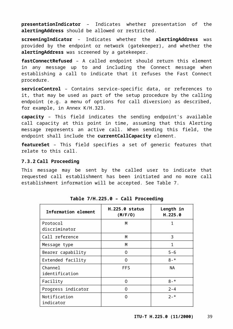
remoteExtensionAddress – Contains the alias address of a called endpoint in cases where this information is needed to traverse multiple Gateways.
tokens – This is some data which may be required to allow the operation. The data shall be inserted into the message if available.
cryptoTokens – Encrypted tokens.
conferences – One or more conferences that may be joined.
h245Address – This is a specific transport address on which the endpoint or gatekeeper sending this facility would like the recipient to establish H.245 signalling. Note that this field may be present when an intermediate signalling entity is conveying the h245Address field from a Call Proceeding message. The receiving entity is instructed to initiate H.245 procedures only when reason is startH245.
fastStart – Used only in the fast connect procedure, fastStart supports the signalling needed to open a logical channel. This uses the OpenLogicalChannel structure defined in ITU-T H.245, but the sender of this indicates the modes it prefers to receive and transmit, and the transport addresses where it expects to receive media streams. This field is present in a Facility message when a routing gatekeeper received it in a Call Proceeding message from the called user and is forwarding the information to the calling user. This field shall not be included by an endpoint.
multipleCalls – If TRUE, this indicates that the sender of the message is capable of signalling multiple calls over a single call signalling connection.
maintainConnection – If TRUE, this indicates that the sender of the message is capable of supporting a signalling connection when no calls are currently signalled over the connection.
fastConnectRefused – A called endpoint should return this element in any message up to and including the Connect message when establishing a call to indicate that it refuses the Fast Connect procedure. This field is present in a Facility message when a routing gatekeeper received it in a Call Proceeding message from the called user and is forwarding the information to the calling user.
serviceControl – Contains service-specific data, or references to it, that could be used by an endpoint or gateway (e.g. for displaying a menu of options to a participant in a call), as described, for example, in Annex K/H.323.
circuitInfo – This field provides information about the SCN circuit or circuits used for this call.
featureSet – This field specifies a set of generic features that relate to this call.
destinationInfo – Contains an EndpointType to allow the caller to determine whether the call involves a gateway or not. This field is present in a Facility message when a routing gatekeeper received it in a Call Proceeding message from the called user and is forwarding the information to the calling user. This field did not exist in the Facility message prior to H.225.0 version 4.
h245SecurityMode – An H.323 entity that receives a Setup message with the h245SecurityCapability set responds with the corresponding, acceptable h245SecurityMode in the Call Proceeding, Alerting, Progress, or Connect. This field is present in a Facility message when a routing gatekeeper received it in a Call Proceeding message from the called user and is forwarding the information to the calling user. This field did not exist in the Facility message prior to H.225.0 version 4.
42 ITU-T H.225.0 (11/2000)

7.4.2 Notify
This message may be sent by an H.323 entity. Processing on receipt is optional.
Follow Table 3-8/Q.931 as modified in Table 17.
Table 17/H.225.0 – Notify
Information element H.225.0 status (M/F/O) Length in H.225.0
Protocol discriminator M 1Call reference M 3Message type M 1Bearer capability O (Note) 5-6Notification indicator M 3Display O 2-82User-user M 2-131NOTE – Included to indicate a change of the bearer capability.
For backward compatibility with systems prior to H.225.0 version 4, the sender of this message shall not include the h4501SupplementaryService or the h245Control field in the h323-message-body field of the User-user information element.
The User-user information element contains the Notify-UUIE defined in the H.225.0 Message Syntax. The Notify-UUIE includes the following:
protocolIdentifier – Set to the version of H.225.0 supported.
callIdentifier – A globally unique call identifier set by the originating endpoint which can be used to associate RAS signalling with the modified Q.931 signalling used in this Recommendation.
tokens – This is some data which may be required to allow the operation. The data shall be inserted into the message if available.
cryptoTokens – Encrypted tokens.
7.4.3 Other messages
The call control messages which can carry optional Facility, Extended Facility, or Notification Indicator information elements are specified in 8.3.
7.5 Q.931 timer values
Two Q.931 timers shall be supported:• The "setup timer" T303 (see Tables 9-1/Q.931 and 9-2/Q.931) defining how long the calling
endpoint shall wait for an Alerting, Call Proceeding, Connect, Release Complete or other message from the called endpoint after it has sent a Setup message. This time-out value shall be at least 4 seconds. Note that some applications may appear in networks which have inherently longer delays (for example, compare the Internet to a local enterprise network or intranet).
• The "establishment timer" T301 (see Tables 9-1/Q.931 and 9-2/Q.931) defining after which time the calling endpoint shall stop waiting for the called endpoint to respond. This timer starts when Alerting is received and normally terminates on Connect or when the caller terminates the call attempt and sends Release Complete. This time-out value shall be 180 seconds (3 minutes) or greater.
Note that the packet-based network-side values of these timers is the same as that used in the SCN.
ITU-T H.225.0 (11/2000) 43

Other timers may be supported as part of optional H.450-series Supplementary Service Recommendations.
7.6 H.225.0 common message elements
This clause describes ASN.1 structures that are used in more than one Registration, Admission, and Status (RAS) messages. Some may also be used in the User-user part of the Q.931 messages.
requestSeqNum in messages is used to keep track of multiple outstanding requests. Any associated response messages (success or failure) shall have the corresponding requestSeqNum returned with it. Retransmitted messages shall have the same requestSeqNum. RequestSeqNum increments by 1 modulo 65536.
The protocolIdentifier is included as part of discovery, registration and Setup/Connect to allow the parties involved to determine the vintage of the implementations involved.
nonStandardParameter: This parameter is optional in the discovery, registration, and Setup/Connect sequences to allow the parties involved to determine the non-standard status of the endpoints involved. A gatekeeper or gateway is not obligated to pass on nonStandardData it does not support or understand as this might interfere with its operations.
The TransportAddress structure is meant to capture the various transport formats and includes any transport-specific scheme in addition to the possibly local reference to a TSAP identifier.
IPv4 and IPv6 addresses shall be encoded with the most significant octet of the address being the first octet in the respective OCTET STRING, e.g. the class B IPv4 address 130.1.2.97 shall have the "130" being encoded in the first octet of the OCTET STRING, followed by the "1" and so forth.
The IPv6 address a148:2:3:4:a:b:c:d shall have the "a1" encoded in the first octet, "48" in the second, "00" in the third, "02" in the fourth and so forth.
A TransportAddress of type ipSourceRoute in which the route SEQUENCE has no entries shall be interpreted as representing the same address as of type ipAddress which contains the same values for both ip and port.
IPX addresses, node, netnum, and port shall be encoded with the most significant octet of each field being the first octet in the respective OCTET STRING.
Note that this structure does not use the Transport Address = "packet-based network Address plus TSAP identifier" language of ITU-T H.323. Instead, the terms common in each transport domain are used.
The EndpointType structure conveys information about the H.323 entity at the end of the signalling link. The H.323 entity would complete one or more of the gatekeeper, gateway, mcu, or terminal message elements. If the H.323 entity has an MC, then the mc Boolean would be TRUE. Clause 6.3/H.323 describes the representation of an MCU when collocated with a gateway; in this case, the H.323 device may include both the gateway and the mcu elements within its EndpointType definition. Presence of the set component indicates that the entity is a Simple Endpoint Type (SET) device as defined, for example, in Annex F/H.323. The bit positions in the set component indicate the type of SET device; their meaning is defined in Annex F/H.323 and other Recommendations that specify SET device types. The supportedTunnelledProtocols field supplies a prioritized list (highest priority first) of supported tunnelled protocols.
The TunnelledProtocol structure identifies a tunnelled signalling protocol as described, for example, in M.1/H.323 and M.2/H.323. The tunnelledProtocolObjectID field is an OBJECT IDENTIFIER identifying the protocol being tunnelled. The tunnelledProtocolAlternateID provides an alternate identifier format. The subIdentifier field allows specification of a particular version of a standard protocol.
44 ITU-T H.225.0 (11/2000)

The TunnelledProtocolAlternateIdentifier structure provides a string-based identifier format for a tunnelled protocol. The protocolType provides the general type of protocol, such as ISUP. The protocolVariant field provides a specific variation of that standard, such as ANSI.
Tunnelled protocols that are defined as of this Recommendation are shown in Tables VI.1 and Table VI.2. Note that tunnelling is not restricted to the protocols listed in those tables.
The GatewayInfo structure contains a protocol element, which allows the gateway to indicate the protocols it supports.
The SupportedProtocols structure indicates a choice of protocols with which an H.323 entity has the capability to interwork. For example, selection of the h310 choice indicates that the entity provides interworking with H.310.
In each supported protocol capability structure (H310Caps, H320Caps, etc.), the dataRatesSupported element indicates the data rates supported for each protocol the device supports. The supportedPrefixes element indicates the prefixes associated with a supported protocol, and in some cases also with the data rates.
The McuInfo structure contains a protocol element, which allows the MCU to indicate the protocols it supports.
The CapacityReportingCapability structure indicates an endpoint's ability to report call capacity information.
The CapacityReportingSpecification structure indicates the call capacity information that an endpoint is requested to report. callStart indicates a request for capacity information at the beginning of the call (i.e. in the ARQ or Setup). callEnd indicates a request for capacity information at the end of the call (i.e. in the DRQ or Release Complete). An empty when sequence indicates a request that the endpoint not report capacity information.
The CallCapacityInfo structure allows an endpoint to indicate its call acceptance capacity for each type of call the endpoint supports. It therefore represents the current idle status of the endpoint. For example, in a voice gateway CallCapacityInfo would represent the number of idle circuits.
The CallCapacity structure allows an endpoint to indicate its maximum capacity for each type of call and its current available capacity for each type of the call the endpoint supports.
The CallsAvailable structure represents a subset of an endpoint's total call capacity. The group field allows the subset to be identified by a group label. The group may be the same as that reported in the CircuitIdentifier.
The DataRate structure provides gateway protocol rate information. channelRate is the basic channel rate in hundreds of bits. channelMultiplier indicates the number of channels at the channelRate. For example, if a gateway supports a 3B call, channelMultiplier = 3 and channelRate = 640 for a 64 kbit/s channel.
The VendorIdentifier structure allows a vendor to identify a product. The vendor element allows identification in terms of country code, extension, and manufacturer code. productId and versionId are text strings that can provide product information.
The H221NonStandard structure allows definition of a nonstandard field. The t35CountryCode element shall identify the country, as described in Annex A/T.35. The t35Extension element shall contain a country code extension that is assigned nationally, unless the t35CountryCode is binary "1111 1111", in which case this field shall contain the country code found in Annex B/T.35. The manufacturerCode shall be assigned nationally and identifies an equipment manufacturer.
The AliasAddress structure is meant to capture the various external address formats that reference a particular transport location on the packet-based network. When registering an address consisting of dialled digits with a gatekeeper, an endpoint shall use the dialedDigits field and shall use only the digits 0-9. When registering an E.164 address with a gatekeeper, an endpoint shall use the
ITU-T H.225.0 (11/2000) 45

e164Number field and shall use only the digits 0-9. When registering or otherwise representing a prefix, an endpoint shall use the dialedDigits field and shall use only the digits 0-9 and "#" and "*". The mobileUIM field is an identification module for systems compatible with 2nd Generation and 3rd Generation wireless networks, and permits interworking with Public Land Mobile Networks as described, for example, in Annex E/H.246.
The AddressPattern structure allows specification of a wildcarded AliasAdress or a range of PartyNumbers. The wildcard field represents the possible wildcarded expansion of the AliasAddress structure. For dialled digits or E.164 numbers this expansion is possible at the end of the number. For email addresses the expansion is possible at the beginning. For example, if wildcard is "+1 303", the pattern could represent any number in the Denver area code. The range field of the AddressPattern structure represents a range of addresses, including the indicated start and end of range.
The mechanisms that an endpoint uses to determine the address type is left as an implementation issue. The representation of the various number types in messages is captured in Table 18. Note that if an endpoint does not know the type or scope of an address, then it should represent this as Private Unknown when coded in Q.931 messages and as a dialedDigits AliasAddress when coded in RAS messages.
Table 18/H.225.0 – Type of number representation mapping
Type of number Q.931 representation H.225.0 information element representation
H.225.0 UUIE representation
Unknown (default and version 1 interoperability mode)
Private Numbering Plan, Type of number = Unknown ("000") (Note 1)
Private Numbering Plan, Type of number = Unknown ("000")
dialedDigits AliasAddress (Note 2)
Private unknown Private Numbering Plan, Type of number = Unknown ("000") (Note 1)
Private Numbering Plan, Type of number = Unknown ("000") (Note 1)
dialedDigits AliasAddress (Note 2)
Private, Level 2 Regional Number
Private Numbering Plan, Type of number = Level 2 Regional Number ("001")
Private Numbering Plan, Type of number = Unknown ("000") (Note 1)
privateNumber of PartyNumber AliasAddress, TypeOfNumber = level2RegionalNumber
Private, Level 1 Regional Number
Private Numbering Plan, Type of number = Level 1 Regional Number ("010")
Private Numbering Plan, Type of number = Unknown ("000") (Note 1)
privateNumber of PartyNumber AliasAddress, TypeOfNumber = level1RegionalNumber
Private, PISN specific Number
Private Numbering Plan, Type of number = PISN specific Number ("011")
Private Numbering Plan, Type of number = Unknown ("000") (Note 1)
privateNumber of PartyNumber AliasAddress, TypeOfNumber = pISNSpecificNumber
Private, Level 0 Regional Number (Local)
Private Numbering Plan, Type of number = Level 0 Regional Number ("100")
Private Numbering Plan, Type of number = Unknown ("000") (Note 1)
privateNumber of PartyNumber AliasAddress, TypeOfNumber = localNumber
46 ITU-T H.225.0 (11/2000)

Table 18/H.225.0 – Type of number representation mapping
Type of number Q.931 representation H.225.0 information element representation
H.225.0 UUIE representation
E.164 Public number, unknown
ISDN/Telephony Numbering Plan, Type of number = Unknown ("000")
ISDN/Telephony Numbering Plan, Type of number = Unknown ("000")
e164Number of PartyNumber AliasAddress, TypeOfNumber = Unknown
E.164 Public number, International Number
ISDN/Telephony Numbering Plan, Type of number = International Number ("001")
ISDN/Telephony Numbering Plan, Type of number = International Number ("001")
e164Number of PartyNumber AliasAddress, TypeOfNumber = internationalNumber
E.164 Public number, National Number
ISDN/Telephony Numbering Plan, Type of number = National Number ("010")
ISDN/Telephony Numbering Plan, Type of number = National Number ("010")
e164Number of PartyNumber AliasAddress, TypeOfNumber = nationalNumber
E.164 Public number, Network Specific Number
ISDN/Telephony Numbering Plan, Type of number = NetworkSpecific Number ("011")
ISDN/Telephony Numbering Plan, Type of number = NetworkSpecific Number ("011")
e164Number of PartyNumber AliasAddress, TypeOfNumber = networkSpecificNumber
E.164 Public number, Subscriber Number
ISDN/Telephony Numbering Plan, Type of number = Subscriber Number ("100")
ISDN/Telephony Numbering Plan, Type of number = Subscriber Number ("100")
e164Number of PartyNumber AliasAddress, TypeOfNumber = subscriberNumber
E.164 Public number, Abbreviated Number
ISDN/Telephony Numbering Plan, Type of number = Abbreviated Number ("110")
ISDN/Telephony Numbering Plan, Type of number = Abbreviated Number ("110")
e164Number of PartyNumber AliasAddress, TypeOfNumber = abbreviatedNumber
NOTE 1 – When Numbering plan identification = Private, the private number digits are encoded in privateNumber of PartyNumber, which includes the type of number. The Type of number field in the information element shall be ignored on reception, and coded according to this table on transmission.NOTE 2 – A privateTypeOfNumber = Unknown PartyNumber AliasAddress shall be treated the same as a dialedDigits AliasAddress.
The MobileUIM structure represents an identification module for systems compatible with 2nd Generation and 3rd Generation wireless networks. The choices available are:• ansi-41-uim – This is for wireless networks defined by American standards.• gsm-uim – This is for wireless networks defined by European standards.
The ANSI-41-UIM structure identifies an identification module for systems compliant with American standards for wireless networks. The choices available are:• imsi – This is for International Mobile Station Identification numbers.• min – This is for Mobile Identification Numbers.• mdn – This is for Mobile Directory Numbers.
ITU-T H.225.0 (11/2000) 47

• msisdn – This is for Mobile Station ISDN numbers.• esn – This is for Electronic Serial Numbers.• mscid – This is for Mobile Switching Center numbers plus Market Identification or System
Identification numbers.• sid – This is for System Identification numbers.• mid – This is for Market Identification numbers.• systemMyTypeCode – This is for vendor identification numbers.• systemAccessType – This is for the system access type.• qualificationInformationCode – This is for the qualification information code.• sesn – This is for SIM Electronic Serial Numbers.• soc – This is for System Operator Codes.
The GSM-UIM structure identifies an identification module for systems compliant with European standards for wireless networks. The choices available are:• imsi – This is for International Mobile Station Identification.• tmsi – This is for Temporary Mobile Station Identification.• msisdn – This is for Mobile Station ISDN numbers.• imei – This is for International Mobile Equipment Identification numbers.• hplmn – This is for Home Public Land Mobile Network Numbers.• vplmn – This is for Visiting Public Land Mobile Network Numbers.
The ExtendedAliasAddress structure provides a means for associating common information with alias addresses. The presentationIndicator indicates whether presentation of the address should be allowed or restricted. The screeningIndicator indicates whether the address was provided by the endpoint or by the network, and whether it has been screened by the network.
The Endpoint structure is used to indicate back-up, redundant, or alternative information about an endpoint:• nonStandardData – Carries information not defined in this Recommendation (for example,
proprietary data).• aliasAddress – This is a list of alias addresses, by which other endpoints may identify this
endpoint.• callSignalAddress – This is the call signalling transport address for this endpoint.• rasAddress – This is the registration and status transport address for this endpoint.• endpointType – This specifies the type of the endpoint.• tokens – Tokens associated with this endpoint (i.e. endpoint described in the Endpoint
structure).• cryptoTokens – CryptoTokens associated with this endpoint (i.e. the endpoint described in
the Endpoint structure).• priority – Used when a SEQUENCE of Endpoints is presented. Endpoints with lower
priority numbers are preferred over endpoints with higher priority numbers. Endpoints without priority numbers are equivalent to those with a priority of 0 (highest priority).
• remoteExtensionAddress – Contains the alias address of an endpoint in cases where this information is needed to traverse multiple gateways.
• destExtraCallInfo – Contains external addresses for multiple calls.• alternateTransportAddresses – Indicates support for transports other than TCP.
48 ITU-T H.225.0 (11/2000)
The AlternateTransportAddresses structure conveys call signalling addresses for transports other than TCP.
The UseSpecifiedTransport structure defines a choice of signalling transport protocols. A value of tcp indicate the TCP protocol. A value of annexE indicates the protocol defined by Annex E/H.323.
The AlternateGK structure is used to indicate a list of alternative, or back-up, gatekeepers:• rasAddress – The transport address used for RAS signalling. • gatekeeperIdentifier – Optionally included to identify the back-up or alternative
gatekeeper. If it is supplied, it shall be included in future RAS messages sent to the back-up gatekeeper.
• needToRegister – Set to TRUE to indicate that the endpoint must register with the alternate before sending other RAS requests.
• priority – Indicates the priority of the gatekeeper back-up or alternative. A lower number implies a higher priority.
The AltGKInfo structure is used to provide information about alternate gatekeepers:• alternateGatekeeper – Sequence of prioritized alternate gatekeepers.• altGKisPermanent – TRUE to indicate that all future RAS signals should be redirected to a
gatekeeper listed in the alternateGatekeeper field; FALSE if only the message that caused the Reject should be redirected. This flag shall be set to TRUE if a needToRegister flag is set to TRUE in the alternateGatekeeper field.
The QseriesOptions structure supplies information to the gatekeeper or other endpoints concerning the support provided by a terminal for optional Q-series protocols. It is used in the ARQ, Setup, and RRQ messages.
The GloballyUniqueID and ConferenceIdentifier are meant to be globally unique identifiers (GloballyUniqueID), the use of which is described in ITU-T H.323. A GloballyUniqueID is encoded with octet zero being encoded first. A GloballyUniqueID is formed according to Table 19.
Table 19/H.225.0 – Globally unique ID formation
Field Data type Octet No. Note
time_low Unsigned 32-bit integer
0-3 The low field of the timestamp
time_mid Unsigned 16-bit integer
4-5 The middle field of the timestamp
time_hi_and_version Unsigned 16-bit integer
6-7 The high field of the timestamp multiplexed with the version number
clock_seq_hi_and_reserved Unsigned 8-bit integer
8 The high field of the clock sequence multiplexed with the variant
clock_seq_low Unsigned 8-bit integer
9 The low field of the clock sequence
node Unsigned 48-bit integer
10-15 The spatially unique node identifier
The GloballyUniqueID consists of a record of 16 octets and shall not contain padding between fields. The total size is 128 bits.
ITU-T H.225.0 (11/2000) 49
To minimize confusion about bit assignments within octets, the GloballyUniqueID record definition is defined only in terms of fields that are integral numbers of octets. The version number is multiplexed with the timestamp (time_high), and the variant field is multiplexed with the clock sequence (clock_seq_high).
The timestamp is a 60-bit value represented by Coordinated Universal Time (UTC) as a count of 100 nanosecond intervals since 00:00:00.00, 15 October 1582 (the date of Gregorian reform to the Christian calendar).
The version number is multiplexed in the 4 most significant bits of the time_hi_and_version field, and is set to 1 (binary "0001").
The variant field determines the layout of the GloballyUniqueID. The structure of a DCE GloballyUniqueID is fixed across different versions. Other GloballyUniqueID variants may not interoperate with a DCE GloballyUniqueID. Interoperability of GloballyUniqueIDs is defined as the applicability of operations such as string conversion, comparison, and lexical ordering across different systems. The variant field consists of a variable number of the MSBs of the clock_seq_hi_and_reserved field (see Table 20).
Table 20/H.225.0 – Contents of the DCE variant field
msb1 msb2 msb3 Description
0 – – Reserved, NCS backward compatibility1 0 – DCE variant1 1 0 Reserved, Microsoft Corporation GUID1 1 1 Reserved for future definition
The clock sequence is required to detect potential losses of monotonicity of the clock. The clock sequence is encoded in the 6 least significant bits of the clock_seq_hi_and_reserved field and in the clock_seq_low field.
The node field consists of the IEEE address, usually the host address. For systems with multiple IEEE 802 nodes, any available node address can be used. The lowest addressed octet (octet number 10) contains the global/local bit and the unicast/multicast bit, and is the first octet of the address transmitted on an 802.3 packet-based network.
The clock sequence value should be changed whenever:• the GloballyUniqueID generator detects that the local value of UTC has gone backward;
this may be due to normal functioning of the DCE Time Service.• the GloballyUniqueID generator has lost its state of the last value of UTC used, indicating
that time may have gone backward; this is typically the case on reboot.
While a node is operational, the GloballyUniqueID generator always saves the last UTC used to create a GloballyUniqueID. Each time a new GloballyUniqueID is created, the current UTC is compared to the saved value and if either the current value is less (the non-monotonic clock case) or the saved value was lost, then the clock sequence is incremented modulo 16 384, thus avoiding production of duplicate GloballyUniqueIDs.
The clock sequence should be initialized to a random number to minimize the correlation across systems.
A GloballyUniqueID is generated according to the following algorithm:1) Determine the values for the UTC-based timestamp and clock sequence to be used in the
GloballyUniqueID.2) Set the time_low field equal to the least significant 32 bits (bits numbered 0 to 31 inclusive)
of the timestamp in the same order of significance.
50 ITU-T H.225.0 (11/2000)
3) Set the time_mid field equal to the bits numbered 32 to 47 inclusive of the timestamp in the same order of significance.
4) Set the 12 least significant bits (bits numbered 0 to 11 inclusive) of the time_hi_and_version field equal to the bits numbered 48 to 59 inclusive of the timestamp in the same order of significance.
5) Set the 4 most significant bits (bits numbered 12 to 15 inclusive) of the time_hi_and_version field to the 4-bit version number corresponding to the GloballyUniqueID version being created, as shown in Table 20.
6) Set the clock_seq_low field to the 8 least significant bits (bits numbered 0 to 7 inclusive) of the clock sequence in the same order of significance.
7) Set the 6 least significant bits (bits numbered 0 to 5 inclusive) of the clock_seq_hi_and_reserved field to the 6 most significant bits (bits numbered 8 to 13 inclusive) of the clock sequence in the same order of significance.
8) Set the 2 most significant bits (bits numbered 6 and 7) of the clock_seq_hi_and_reserved to 0 and 1, respectively.
9) Set the node field to the 48-bit IEEE address in the same order of significance as the address.
If a system wants to generate a GloballyUniqueID but has no IEEE 802 compliant network card or other source of IEEE 802 addresses, then an alternative method should be used to generate a replacement value for the address. The ideal solution is to obtain a 47-bit cryptographic quality random number, and use it as the most significant 47 bits of the node ID, with the least significant bit of the first octet of the node ID set to 1. This bit is the unicast/multicast bit, which will never be set in IEEE 802 addresses obtained from network cards; hence, there can never be a conflict between GloballyUniqueIDs generated by machines with and without network cards.
If a system does not have a primitive to generate cryptographic quality random numbers, then in most systems there are usually a fairly large number of sources of randomness available from which one can be generated. Such sources are system specific, but often include the percentage of memory in use, the size of main memory in bytes, the amount of free main memory in bytes, the size of the paging or swap file in bytes, free bytes of paging or swap file, the total size of user virtual address pace in bytes, the total available user address space bytes, the size of boot disk drive in bytes, the free disk space on boot drive in bytes, the current time, the amount of time since the system booted, the individual sizes of files in various system directories, etc.
For use in human-readable text, a GloballyUniqueID string representation is specified as a sequence of fields, some of which are separated by single dashes.
Each field is treated as an integer and has its value printed as a zero-filled hexadecimal digit string with the most significant digit first. The hexadecimal values a to f inclusive are output as lower case characters, and are case insensitive on input. The sequence is the same as the GloballyUniqueID constructed type.
The formal definition of the GloballyUniqueID string representation is provided by the following extended BNF:
UUID = <time_low> <hyphen> <time_mid> <hyphen> <time_high_and_version> <hyphen> <clock_seq_and_reserved> <clock_seq_low> <hyphen> <node>time_low = <hexOctet> <hexOctet> <hexOctet> <hexOctet>time_mid = <hexOctet> <hexOctet>time_high_and_version = <hexOctet> <hexOctet>clock_seq_and_reserved = <hexOctet>clock_seq_low = <hexOctet>node = <hexOctet><hexOctet><hexOctet> <hexOctet><hexOctet><hexOctet>
ITU-T H.225.0 (11/2000) 51

hexOctet = <hexDigit> <hexDigit>phexDigit = <digit> | <a> | <b> | <c> | <d> | <e> | <f>digit = "0" | "1" | "2" | "3" | "4" | "5" | "6" | "7" | "8" | "9"hyphen = "-"a = "a" | "A"b = "b" | "B"c = "c" | "C"d = "d" | "D"e = "e" | "E"f = "f" | "F"
The following is an example of the string representation of a GloballyUniqueID:
f81d4fae-7dec-11d0-a765-00a0c91e6bf6
timeToLive is a number of seconds that a registration is to be considered valid.
The H248PackagesDescriptor structure is a PackagesDescriptor as defined in ITU-T H.248, in binary format.
The H248SignalsDescriptor structure is a SignalsDescriptor as defined in ITU-T H.248, in binary format.
The FeatureDescriptor structure is a GenericData element that is used to generically identify a feature.
CircuitInfo – This structure provides information about the SCN circuit or circuits used for this call. The sourceCircuitID field provides information about the source circuit when the call originates on the SCN, and might be used by an ingress gateway to report the source circuit identifier to the gatekeeper. The destinationCircuitID provides information about the destination circuit when the call terminates on the SCN, and might be used by a gatekeeper to select a destination circuit on an egress gateway.
The CircuitIdentifier structure designates a facility for purposes of reporting by a gateway or selection by a gatekeeper. The CircuitIdentifier structure supports a variety of interfaces.
The CicInfo structure designates SS7 bearer channels. The cic field is the circuit identifier code as defined in ITU-T Q.763, encoded with the least significant bits in the first octet and the most significant bits in the last octet. The pointCode field contains the point code as defined in ITU-T Q.763. The first octet of the pointCode identifies the network (network indicator code) and the remaining octets identify the SS7 point code value. The cic and pointCode fields are variable in length to allow for national variants.
The GroupID structure identifies a physical or logical group and a member (or set of members) within that group. For example, group could identify a physical interface, while member could identify a particular DS0 on that interface. If the member field is omitted, the gateway is expected to select an available facility in the specified group.
The ServiceControlDescriptor structure contains service-specific data, or references to it, intended for user presentation or other service control communications as described, for example, in Annex K/H.323. The following options are possible:• url – This selection contains a URL-referenced protocol or resource. • signal – This selection contains a SignalsDescriptor as defined in ITU-T H.248, in binary
format. The optional streamID and notifyCompletion elements shall be omitted from the Signal sequence in the SignalsDescriptor.
• nonStandard – This selection contains information not defined in this Recommendation (for example, proprietary data).
• callCreditServiceControl – This selection contains information related to controlling the duration of a call and advising the user of account balance information.
52 ITU-T H.225.0 (11/2000)

The ServiceControlSession structure contains a description of a service control session as described, for example, in Annex K/H.323. It contains the following fields:• sessionId – An integer identifying this session that is unique for the client. Note that the
identifiers received through different signalling paths (e.g. RAS and call signalling) are orthogonal and may overlap.
• contents – A ServiceControl structure with the relevant contents, or communication mechanism.
• reason – Indicates whether this is a new session (open) or a modification to an existing session (refresh), or that the session is being terminated by the provider (close) and existing resources such as a GUI, etc., should be closed.
The RasUsageInfoTypes structure lists types of usage information that may be reported by an endpoint to a gatekeeper. The endpoint uses this structure to indicate its capabilities with respect to collecting and reporting usage information, and the gatekeeper uses this structure to request usage information of particular types. The nonStandardUsageTypes field allows a vendor to refer to proprietary usage information types. The startTime and endTime fields refer to the times at which a call started and ended, respectively. The terminationCause parameter refers to the reason that the call ended.
The RasUsageSpecification structure is a template that allows a gatekeeper to request particular types of usage information at specific points in a call. The when field indicates the point or points in the call at which time the endpoint is requested to report the information; start refers to the start of the call, end refers to the end of the call, and inIrr refers to unsolicited IRR messages. The callStartingPoint field defines the point or points in the call that shall be considered the start of the call for the purposes of reporting usage information; a value of connect refers to transmission or reception of the Connect message, and a value of alerting refers to transmission or reception of the Alerting message. The required field indicates the types of usage information that the endpoint is required to report. A RasUsageSpecification structure in which nothing is selected in either the when or required fields indicates a request to disable the reporting of usage information.
The RasUsageInformation structure is a collection of usage data pertaining to a particular call. The nonStandardUsageFields field allows a vendor to list usage information of proprietary types. The alertingTime field indicates the time at which the Alerting message was sent or received. The connectTime field indicates the time at which the Connect message was sent or received. The endTime field indicates the time at which the Release Complete message was sent or received.
The CallTerminationCause structure indicates the reason for the end of a call. The releaseCompleteReason field indicates the reason that was specified in the Release Complete message. The releaseCompleteCauseIE field provides the Cause IE from the Release Complete message.
The BandwidthDetails structure defines additional bandwidth usage information that is not available in the BandWidth structure. The sender field is set to TRUE if the message is sent by the sender of the stream, or FALSE if sent by the receiver. The multicast field is set to TRUE if the stream is multicast, or FALSE otherwise. The bandwidth field indicates the bandwidth used for the stream in units of hundreds of bits per second. The rtcpAddresses field indicates the RTCP addresses used for the media stream.
The CallCreditCapability structure indicates certain capabilities of an endpoint related to billing for a call. By default, an endpoint is assumed not to have these optional capabilities. If a field in this structure is not included, this indicates that the status of the capability represented by that field has not changed since the last time it was reported. The canDisplayAmountString field indicates whether the endpoint can display a text string that contains the amount of currency in a user's account. The canEnforceDurationLimit field indicates whether an endpoint has the capability to disengage a call when a call duration limit indicated by the gatekeeper has elapsed.
ITU-T H.225.0 (11/2000) 53

The CallCreditServiceControl structure allows a gatekeeper to provide certain billing-related control and information to an endpoint. This structure provides the following fields:• amountString – This field indicates the amount of money in a user's account, e.g. "$10.00".
The string shall include the appropriate currency symbol. Note that standard abbreviations for currency types, such as "USD" for United States dollars, are defined by ISO 4217. The amountString field shall be encoded in Basic ISO/IEC 10646-1 (Unicode).
• billingMode – This field indicates the billing mode for this call. A mode of debit indicates that the call will result in charges against the amount of money available in a user's account. A mode of credit indicates that the call will result in charges to be paid at a later time. An endpoint could use this information, for example, to determine the type of announcement to play or display.
• callDurationLimit – This field indicates the remaining amount of time allowed for a particular call.
• enforceCallDurationLimit – This field indicates whether the endpoint is requested to disengage the call after the amount of time indicated by callDurationLimit has elapsed. If this field is not provided, the endpoint shall interpret this to indicate that the directive has not changed from its previous state.
• callStartingPoint – This field indicates the point in the call that timing is requested to begin if call duration enforcement is provided by the endpoint.
The GenericData structure consists of an id to identify the data, and the parameters field to convey the actual parameters.
The GenericIdentifier structure provides various ways to identify an object.
The EnumeratedParameter structure provides a generic parameter. It consists of an id to identify the parameter, and a content field to convey any associated data.
The Content structure supports a number of different data types, including raw, text, unicode, bool, number8, number16, number32, id, alias, transport, compound and nested. This allows for flexible definition of a generic parameter. The raw choice allows for a parameter or set of parameters whose actual data structure is defined elsewhere; for example, it could consist of PER-encoded ASN.1 or data in type-length-value form, or could be an encapsulated message of another signalling protocol.
The FeatureSet structure allows an entity to specify generic feature information. The entity specifies the set of features that it requires for successful completion of the call using the neededFeatures field, the set of features that it prefers but does not require using the desiredFeatures field, and the set of features that it supports in the supportedFeatures field. The replacementFeatureSet BOOLEAN is set to TRUE to indicate that this feature set replaces any previously sent feature set, or FALSE otherwise.
The TransportChannelInfo structure provides information about a media transport channel. The sendAddress field is the transport address of the sender, and the recvAddress is the transport address of the receiver.
The RTPSession structure provides a description of an RTP session. It has the following fields:• rtpAddress – This field provides the send and receive addresses of the RTP stream.• rtcpAddress – This field provides the send and receive addresses of RTCP messages.• cname – This field provides the CNAME as specified in clause 6 and in Annex A.• ssrc – This field is used to identify the source of an RTP stream, as described in clause 6 and
in Annex A.• sessionId – This field provides the identifier of this RTP session, as described in ITU-T
H.245.
54 ITU-T H.225.0 (11/2000)

• associatedSessionIds – This field provides the identifiers of associated RTP sessions, as described in ITU-T H.245.
• multicast – This field indicates whether this is a multicast session.• bandwidth – This field indicates the bandwidth used for the stream in units of hundreds of
bits per second.
7.7 Required support of RAS messages
Table 21 shows the RAS messages that are supported by different endpoint types.
Table 21/H.225.0 – Status of RAS messages
RAS Message Endpoint(Tx)
Endpoint(Rx)
Gatekeeper(Tx)
Gatekeeper (Rx)
GRQ O MGCF O MGRJ O MRRQ M MRCF M MRRJ M MURQ O M O MUCF M O M OURJ O O M OARQ M MACF M MARJ M MBRQ M M O MBCF M (Note 1) M M OBRJ M M M OIRQ M MIRR M MIACK O CMINAK O CMDRQ M M O MDCF M M M MDRJ M (Note 2) M M MLRQ O O MLCF O M OLRJ O M ONSM O O O OXRS M M M MRIP CM M CM MRAI O MRAC O M
ITU-T H.225.0 (11/2000) 55

Table 21/H.225.0 – Status of RAS messages
RAS Message Endpoint(Tx)
Endpoint(Rx)
Gatekeeper(Tx)
Gatekeeper (Rx)
SCI O O O OSCR O O O OM: Mandatory, O: Optional, F: Forbidden, CM: Conditionally Mandatory, blank: "Not Applicable".NOTE 1 – If a gatekeeper sends a BRQ requesting a lower rate, the endpoint shall reply with BCF if the lower rate is supported, otherwise with BRJ. If a gatekeeper sends a BRQ requesting a higher rate, the endpoint may reply with BCF or BRJ.NOTE 2 – Terminal shall not send DRJ in response to a valid DRQ from its gatekeeper.
7.8 Terminal and Gateway Discovery messages
The GRQ message requests that any gatekeeper receiving it respond with a GCF granting it permission to register. The GRJ is a rejection of this request indicating that the requesting endpoint should seek another gatekeeper.
7.8.1 GatekeeperRequest (GRQ)
Note that one GRQ is sent per logical endpoint; thus, an MCU or a Gateway might send many.
The GRQ message includes the following:
requestSeqNum – This is a monotonically increasing number unique to the sender. It shall be returned by the receiver in any messages associated with this specific message.
protocolIdentifier – Identifies the H.225.0 vintage of the sending endpoint.
nonStandardData – Carries information not defined in this Recommendation (for example, proprietary data).
rasAddress – This is the transport address that this endpoint uses for registration and status messages.
endpointType – This specifies the type(s) of the endpoint that is registering (the MC bit shall not be set by itself).
gatekeeperIdentifier – String to identify the gatekeeper from which the terminal would like to receive permission to register. A missing or null string gatekeeperIdentifier indicates that the terminal is interested in any available gatekeeper.
callServices – Provides information on support of optional Q-series protocols to gatekeeper and called terminal.
endpointAlias – A list of alias addresses, by which other terminals may identify this terminal.
alternateEndpoints – A sequence of prioritized endpoint alternatives for rasAddress, endpointType, or endpointAlias.
tokens – This is some data which may be required to allow the operation. The data shall be inserted into the message if available.
cryptoTokens – Encrypted tokens.
authenticationCapability – This indicates the authentication mechanisms supported by the endpoint.
algorithmOIDs – Indicates the entire set of encryption algorithms supported by the endpoint.
56 ITU-T H.225.0 (11/2000)

integrity – Indicates to the recipient which integrity mechanism is to be applied on the RAS messages.
integrityCheckValue – Provides improved message integrity/message authentication of the RAS messages. The cryptographically based integrity check value is computed by the sender applying a negotiated integrity algorithm and the secret key upon the entire message. Prior to integrityCheckValue computation, this field shall be ignored and shall be empty. After computation, the sender puts the computed integrity check value in the integrityCheckValue field and transmits the message.
supportsAltGK – Indicates whether the endpoint supports the alternate gatekeeper mechanism.
featureSet – This field specifies a set of generic features.
genericData – This field is a list of generic elements related to features that are defined outside of the base H.225.0 specification. These parameters may be used, for example, for tunnelling information transparently through RAS.
7.8.2 GatekeeperConfirm (GCF)
The GCF message includes the following:
requestSeqNum – This shall be the same value that was passed in the GRQ.
protocolIdentifier – Identifies the vintage of the accepting gatekeeper.
nonStandardData – Carries information not defined in this Recommendation (for example, proprietary data).
gatekeeperIdentifier – String to identify gatekeeper that is sending the GCF.
rasAddress – This is the transport address that the gatekeeper uses for registration and status messages.
alternateGatekeeper – Sequence of prioritized alternatives for gatekeeperIdentifier and rasAddress.
authenticationMode – This indicates the authentication mechanism to be used. The gatekeeper shall choose authenticationMode from authenticationCapability provided by the endpoint in GRQ.
tokens – This is some data which may be required to allow the operation. The data shall be inserted into the message if available.
cryptoTokens – Encrypted tokens.
algorithmOID – Indicates the encryption algorithm required by the gatekeeper.
integrity – Indicates to the recipient which integrity mechanism is to be applied on the RAS messages.
integrityCheckValue – Provides improved message integrity/message authentication of the RAS messages. The cryptographically based integrity check value is computed by the sender applying a negotiated integrity algorithm and the secret key upon the entire message. Prior to integrityCheckValue computation, this field shall be ignored and shall be empty. After computation, the sender puts the computed integrity check value in the integrityCheckValue field and transmits the message.
featureSet – This field specifies a set of generic features.
genericData – This field is a list of generic elements related to features that are defined outside of the base H.225.0 specification. These parameters may be used, for example, for tunnelling information transparently through RAS.
ITU-T H.225.0 (11/2000) 57

7.8.3 GatekeeperReject (GRJ)
The GRJ message includes the following:
requestSeqNum – This shall be the same value that was passed in the GRQ.
protocolIdentifier – Identifies the vintage of the rejecting gatekeeper.
nonStandardData – Carries information not defined in this Recommendation (for example, proprietary data).
gatekeeperIdentifier – String to identify gatekeeper that is sending the GRJ.
rejectReason – Codes for why the GRQ was rejected by this gatekeeper. A reason of genericDataReason indicates that the request was rejected as a result of a generic element or feature; in this case, additional information may be specified in the genericData field.
altGKInfo – Optional information about alternative gatekeepers.
tokens – This is some data which may be required to allow the operation. The data shall be inserted into the message if available.
cryptoTokens – Encrypted tokens.
integrityCheckValue – Provides improved message integrity/message authentication of the RAS messages. The cryptographically based integrity check value is computed by the sender applying a negotiated integrity algorithm and the secret key upon the entire message. Prior to integrityCheckValue computation, this field shall be ignored and shall be empty. After computation, the sender puts the computed integrity check value in the integrityCheckValue field and transmits the message.
featureSet – This field specifies a set of generic features.
genericData – This field is a list of generic elements related to features that are defined outside of the base H.225.0 specification. These parameters may be used, for example, for tunnelling information transparently through RAS.
7.9 Terminal and Gateway Registration messages
The RRQ is a request from a terminal to a gatekeeper to register. If the gatekeeper responds with a RCF, the terminal shall use the responding gatekeeper for future calls. If the gatekeeper responds with a RRJ, the terminal must seek another gatekeeper to register with.
7.9.1 RegistrationRequest (RRQ)
The RRQ message includes the following:
requestSeqNum – This is a monotonically increasing number unique to the sender. It shall be returned by the receiver in any response associated with this specific message.
protocolIdentifier – Identifies the H.225.0 vintage of the sending endpoint.
nonStandardData – Carries information not defined in this Recommendation (for example, proprietary data).
discoveryComplete – Set to TRUE if the requesting endpoint has preceded this message with the gatekeeper discovery procedure; set to FALSE if registering only. Note that registration may age, and the endpoint will get a failure on an RRQ or ARQ with a reason code of discoveryRequired or notRegistered respectively. This indicates that the endpoint should perform the discovery procedure (either dynamic or static) before issuing the RRQ with discoveryComplete set to TRUE.
callSignalAddress – This is the call signalling transport address for this endpoint. If multiple transports are supported, they shall be registered all at once.
58 ITU-T H.225.0 (11/2000)

rasAddress – This is the registration and status transport address for this endpoint.
terminalType – This specifies the type(s) of the endpoint that is(are) registering; note that the mc bit shall not be set by itself; either the terminal, mcu, gateway, or gatekeeper bit shall also be set. If vendor information is provided, this information shall be identical to that in endpointVendor. If the terminalType is gateway or mcu, then the optional supportedPrefixes value is a list of prefix addresses by which other endpoints may identify SCN protocols and data rates supported by this entity. This field may be used in addition to or as an alternative to the terminalAlias and terminalAliasPattern fields. All of the endpoint's supported prefixes shall be included in each RRQ unless the additiveRegistration option is specified, in which case the supported prefixes in an RRQ shall be added to the list of currently registered prefixes for the endpoint. With the additive RRQ, supported prefixes already registered to this endpoint shall be considered still registered. Note that prefixes are not part of a PartyNumber (E.164 or others). In order to register a PartyNumber (or a range or pattern of them), the endpoint shall use the terminalAlias and terminalAliasPattern fields as described below.
terminalAlias – This optional value is a list of alias addresses, by which other terminals may identify this terminal. This field may be used in addition to or as an alternative to the terminalAliasPattern and supportedPrefixes fields. If the terminalAlias is null, a dialedDigits address may be assigned by the gatekeeper, and included in the RCF. If an email-ID is available for the endpoint, it should be registered. Note that multiple alias addresses may refer to the same transport addresses. All of the endpoint's aliases that it desires to register shall be included in this list unless the additiveRegistration option is specified, in which case the endpoint aliases in an RRQ shall be added to the list of aliases currently registered for the endpoint.
gatekeeperIdentifier – String to identify the gatekeeper that the terminal wishes to register with.
endpointVendor – Information about the endpoint vendor.
alternateEndpoints – A sequence of prioritized endpoint alternatives for callSignalAddress, rasAddress, terminalType, or terminalAlias.
timeToLive – Duration of the validity of the registration, in seconds. After this time the gatekeeper may consider the registration stale.
tokens – This is some data which may be required to allow the operation. The data shall be inserted into the message if available.
cryptoTokens – Encrypted tokens.
integrityCheckValue – Provides improved message integrity/message authentication of the RAS messages. The cryptographically based integrity check value is computed by the sender applying a negotiated integrity algorithm and the secret key upon the entire message. Prior to integrityCheckValue computation, this field shall be ignored and shall be empty. After computation, the sender puts the computed integrity check value in the integrityCheckValue field and transmits the message.
keepAlive – If set to TRUE, indicates that the endpoint has sent this RRQ as a "keep alive". An endpoint can send a lightweight RRQ consisting of only rasAddress, keepAlive, endpointIdentifier, gatekeeperIdentifier, tokens, and timeToLive. A gatekeeper in receipt of RRQ with a keepAlive field set to TRUE should ignore fields other than endpointIdentifier, gatekeeperIdentifier, tokens, and timeToLive. The rasAddress in a lightweight RRQ shall only be used by a gatekeeper as the destination for an RRJ when the endpoint is not registered.
endpointIdentifier – The endpointIdentifier provided by the gatekeeper during the original RCF.
willSupplyUUIEs – If set to TRUE, this indicates that the endpoint will supply Q.931 message information in IRR messages if requested by the gatekeeper.
ITU-T H.225.0 (11/2000) 59

maintainConnection – If TRUE, this indicates that the sender of the message is capable of supporting a signalling connection when no calls are currently signalled over the connection.
alternateTransportAddresses – This field conveys call signalling addresses for transports other than TCP. Inclusion of an address indicates support for the corresponding transport.
additiveRegistration – If present, this field indicates that this message is an "additive" RRQ, meaning that the endpoint has sent this RRQ as an addition of information to an existing registration. An endpoint may send an additive RRQ consisting of only callSignalAddress, rasAddress, terminalType, terminalAlias, terminalAliasPattern, alternateEndpoints, endpointIdentifier, gatekeeperIdentifier, and tokens. A gatekeeper in receipt of an RRQ with the additiveRegistration field present shall ignore fields other than these. The rasAddress in an additive RRQ shall be used by a gatekeeper as the destination for the subsequent RRJ if the endpoint is not registered or if the terminalAlias and/or terminalAliasPattern conflicts with the gatekeeper's registration policy.
terminalAliasPattern – This optional value is a list of address patterns specifying aliases and addresses by which other endpoints may identify this endpoint. This field may be used in addition to or as an alternative to the terminalAlias and supportedPrefixes fields. All of the endpoint's aliases and addresses shall be included in each RRQ unless the additiveRegistration option is TRUE, in which case the endpoint aliases and addresses in the RRQ shall be added to the list of aliases currently registered for the endpoint.
supportsAltGK – Indicates whether the endpoint supports the alternate gatekeeper mechanism.
usageReportingCapability – This field may be included by the endpoint to advertise its ability to collect and report various types of usage information.
multipleCalls – If TRUE, this field indicates that the sender of the message is capable of signalling multiple calls over a single call signalling connection.
supportedH248Packages – This field indicates a list of H.248 packages supported by this endpoint.
callCreditCapability – This field describes certain billing-related capabilities of this endpoint.
capacityReportingCapability – This field describes the endpoint's ability to report call capacity information.
capacity – This field indicates the endpoint's maximum and current call capacity. When sending this field, the endpoint shall include the maximumCallCapacity and currentCallCapacity elements.
featureSet – This field specifies a set of generic features.
genericData – This field is a list of generic elements related to features that are defined outside of the base H.225.0 specification. These parameters may be used, for example, for tunnelling information transparently through RAS.
7.9.2 RegistrationConfirm (RCF)
The RCF message includes the following:
requestSeqNum – This shall be the same value that was passed in the RRQ.
protocolIdentifier – Identifies the vintage of the accepting gatekeeper.
nonStandardData – Carries information not defined in this Recommendation (for example, proprietary data).
callSignalAddress – This is an array of transport addresses for H.225.0 call signalling messages; one for each transport that the gatekeeper will respond to. This address includes the TSAP identifier.
terminalAlias – This optional value is a list of alias addresses, by which other terminals may identify this terminal. This field may be used in addition to or as an alternative to the
60 ITU-T H.225.0 (11/2000)

terminalAliasPattern and supportedPrefixes fields. It specifies the alias addresses that have been accepted from those proposed in the associated RRQ message. If none were proposed in the RRQ, this list gives aliases assigned by the gatekeeper.
gatekeeperIdentifier – String to identify the gatekeeper that has accepted the terminals registration.
endpointIdentifier – A gatekeeper assigned terminal identity string; shall be echoed in subsequent RAS messages.
alternateGatekeeper – Sequence of prioritized alternatives for gatekeeperIdentifer and rasAddress.
timeToLive – Duration of the validity of the registration, in seconds. After this time the gatekeeper may consider the registration stale.
tokens – This is some data which may be required to allow the operation. The data shall be inserted into the message if available.
cryptoTokens – Encrypted tokens.
integrityCheckValue – Provides improved message integrity/message authentication of the RAS messages. The cryptographically based integrity check value is computed by the sender applying a negotiated integrity algorithm and the secret key upon the entire message. Prior to integrityCheckValue computation, this field shall be ignored and shall be empty. After computation, the sender puts the computed integrity check value in the integrityCheckValue field and transmits the message.
willRespondToIRR – True if the gatekeeper will send an IACK or INAK message in response to an unsolicited IRR message with its needsResponse field set to TRUE.
preGrantedARQ – Indicates events for which the gatekeeper has pre-granted admission. This allows for faster call setup times in environments where admission is guaranteed through means other than the ARQ/ACF exchange. Note that even if these fields are set to TRUE, an endpoint can still send an ARQ to the gatekeeper for reasons such as address translation, or the endpoint does not support this modified signalling mode. If the preGrantedARQ sequence is not present, then ARQ signalling shall be used in all cases. The fields are:• makeCall – If the makeCall flag is TRUE, then the gatekeeper has pre-granted permission
to the endpoint to initiate calls without first sending an ARQ. If the makeCall flag is FALSE, the endpoint shall always send ARQ to get permission to make a call.
• useGKCallSignalAddressToMakeCall – If the makeCall and useGKCallSignalAddressToMakeCall flags are both set to TRUE, then if the endpoint does not send an ARQ to the gatekeeper to make a call, the endpoint shall send all H.225 call signalling to the gatekeeper call signalling channel.
• answerCall – If the answerCall flag is TRUE, then the gatekeeper has pre-granted permission to the endpoint to answer calls without first sending an ARQ. If the answerCall flag is FALSE, the endpoint shall always send ARQ to get permission to answer a call.
• useGKCallSignalAddressToAnswer – If the answerCall and useGKCallSignalAddressToAnswer flags are both set to TRUE, then when an endpoint does not send an ARQ to the gatekeeper to answer a call, the endpoint shall ensure that all H.225.0 call signalling comes from the gatekeeper. If an endpoint has been instructed to use the gatekeeper when answering, but it does not know whether an incoming call has come from the gatekeeper (which may involve looking at the transport address), the endpoint shall issue ARQ irrespective of the state of the useGKCallSignalAddressToAnswer flag.
ITU-T H.225.0 (11/2000) 61

• irrFrequencyInCall – This indicates the frequency, in seconds, of IRR messages sent to the gatekeeper when the endpoint is in one or more calls. If it is not present, the gatekeeper does not want unsolicited IRR messages. When the endpoint is sending these IRR messages, the call reference value shall be made unique for the terminal, as it would have been generated in an Admission Request. However, this is not a "normal" CRV, and cannot be reused for further communication (DRQ, IRQ or BRQ). The call identifier shall be the same as used in the call signalling channel messages for the related call.
• totalBandwidthRestriction – This field limits the total use of bandwidth for the endpoint when in calls. If it is not present, there is no constant bandwidth restriction.
• alternateTransportAddresses – This field conveys call signalling addresses for transports other than TCP. Inclusion of an address indicates support for the corresponding transport.
• useSpecifiedTransport – This field allows the gatekeeper to instruct the endpoint as to which signalling transport protocol to use for making calls. If this field is included and the specified transport is not tcp, then the alternateTransportAddresses shall also be included in this message.
maintainConnection – If TRUE, this indicates that the gatekeeper (in the case of gatekeeper routing) is capable of supporting a signalling connection when no calls are currently signalled over the connection.
serviceControl – Contains service specific data or addressing information that the endpoint may use for non-call related service control communication with the network as described, for example, in Annex K/H.323.
supportsAdditiveRegistration – If present, this field indicates that the gatekeeper supports additive registration capabilities. If not present, the gatekeeper does not support additive registration.
terminalAliasPattern – This optional value is a list of address patterns specifying aliases and addresses by which other endpoints may identify this endpoint. This field may be used in addition to or as an alternative to the terminalAlias and supportedPrefixes fields. It specifies the aliases and addresses that have been accepted from those proposed in the associated RRQ message. If none were proposed in the RRQ, this list gives aliases and addresses assigned by the gatekeeper.
supportedPrefixes – This optional value is a list of prefixes by which other endpoints may identify this endpoint. This field may be used in addition to or as an alternative to the terminalAlias and terminalAliasPattern fields. It specifies the address prefixes that have been accepted from those proposed in the associated RRQ message. If none were proposed in the RRQ, this list gives prefixes assigned by the gatekeeper.
usageSpec – This field may be included by the gatekeeper to request that the endpoint collect and report the indicated call usage information at the specified points in time.
featureServerAlias – This field is reserved for future use by the ITU-T for a stimulus-based protocol.
capacityReportingSpec – This field indicates the type of call capacity information that an endpoint is requested to report.
featureSet – This field specifies a set of generic features.
genericData – This field is a list of generic elements related to features that are defined outside of the base H.225.0 specification. These parameters may be used, for example, for tunnelling information transparently through RAS.
62 ITU-T H.225.0 (11/2000)

7.9.3 RegistrationReject (RRJ)
The RRJ message includes the following:
requestSeqNum – This shall be the same value that was passed in the RRQ.
protocolIdentifier – Identifies the vintage of the rejecting gatekeeper.
nonStandardData – Carries information not defined in this Recommendation (for example, proprietary data).
rejectReason – The reason for the rejection of the registration. This field may contain an invalidTerminalAliases value, in which case it contains a list of aliases, addresses and supported prefixes that were determined to be invalid in the associated RRQ message. A reason of genericDataReason indicates that the request was rejected as a result of a generic element or feature; in this case, additional information may be specified in the genericData field.
gatekeeperIdentifier – String to identify the gatekeeper that has rejected the terminal's registration.
altGKInfo – Optional information about alternative gatekeepers.
tokens – This is some data which may be required to allow the operation. The data shall be inserted into the message if available.
cryptoTokens – Encrypted tokens.
integrityCheckValue – Provides improved message integrity/message authentication of the RAS messages. The cryptographically based integrity check value is computed by the sender applying a negotiated integrity algorithm and the secret key upon the entire message. Prior to integrityCheckValue computation, this field shall be ignored and shall be empty. After computation, the sender puts the computed integrity check value in the integrityCheckValue field and transmits the message.
featureSet – This field specifies a set of generic features.
genericData – This field is a list of generic elements related to features that are defined outside of the base H.225.0 specification. These parameters may be used, for example, for tunnelling information transparently through RAS.
7.10 Terminal/Gatekeeper Unregistration messages
7.10.1 UnregistrationRequest (URQ)
The URQ requests that the association between a terminal and a gatekeeper be broken. Note that unregister is bidirectional, i.e. a gatekeeper can request a terminal to consider itself unregistered, and a terminal can inform a gatekeeper that it is revoking a previous registration.
The URQ message includes the following:
requestSeqNum – This is a monotonically increasing number unique to the sender. It shall be returned by the receiver in any response associated with this specific message.
callSignalAddress – This is one or more of the transport call signalling addresses for this endpoint which are to be unregistered.
endpointAlias – This optional value is a list of alias addresses, by which other terminals may identify this terminal. This field may be used in addition to or as an alternative to the endpointAliasPattern and supportedPrefixes fields. If this field, the endpointAliasPattern field, and the supportedPrefixes field are not present, all aliases are unregistered in a single message. The dialedDigits value, if assigned, is required. Only values listed here are unregistered; this allows, for example, an h323-ID to be unregistered while leaving the dialedDigits value registered.
ITU-T H.225.0 (11/2000) 63

nonStandardData – Carries information not defined in this Recommendation (for example, proprietary data).
endpointIdentifier – Confirmation of identity; not sent by the gatekeeper.
alternateEndpoints – A sequence of prioritized endpoint alternatives for callSignalAddress or endpointAlias.
gatekeeperIdentifier – A gatekeeperIdentifier which the endpoint received in the alternateGatekeeper list in an RCF from the gatekeeper when it registered or in a previous URJ message.
tokens – This is some data which may be required to allow the operation. The data shall be inserted into the message if available.
cryptoTokens – Encrypted tokens.
integrityCheckValue – Provides improved message integrity/message authentication of the RAS messages. The cryptographically based integrity check value is computed by the sender applying a negotiated integrity algorithm and the secret key upon the entire message. Prior to integrityCheckValue computation, this field shall be ignored and shall be empty. After computation, the sender puts the computed integrity check value in the integrityCheckValue field and transmits the message.
reason – Used when the gatekeeper sends the URQ to indicate why the gatekeeper considers the endpoint unregistered. A reason of maintenance indicates that the gatekeeper or endpoint is being taken down for maintenance.
endpointAliasPattern – This optional value is a list of address patterns specifying aliases and addresses by which other endpoints may identify this endpoint. This field may be used in addition to or as an alternative to the endpointAlias and supportedPrefixes fields. If this field, the endpointAlias field and the supportedPrefixes field are not present, all aliases and addresses are unregistered in a single message. Otherwise, only values listed here are unregistered.
supportedPrefixes – This optional value is a list of prefixes by which other endpoints may identify this endpoint. This field may be used in addition to or as an alternative to the terminalAlias and terminalAliasPattern fields. If this field, the endpointAlias field and the endpointAliasPattern field are not present, all aliases and addresses are unregistered in a single message. Otherwise, only values listed here are unregistered.
alternateGatekeeper – Sequence of prioritized alternatives for gatekeeperIdentifier and rasAddress.
genericData – This field is a list of generic elements related to features that are defined outside of the base H.225.0 specification. These parameters may be used, for example, for tunnelling information transparently through RAS.
7.10.2 UnregistrationConfirm (UCF)
The UCF message includes the following:
requestSeqNum – This shall be the same value that was passed in the URQ.
nonStandardData – Carries information not defined in this Recommendation (for example, proprietary data).
tokens – This is some data which may be required to allow the operation. The data shall be inserted into the message if available.
cryptoTokens – Encrypted tokens.
integrityCheckValue – Provides improved message integrity/message authentication of the RAS messages. The cryptographically based integrity check value is computed by the sender applying a
64 ITU-T H.225.0 (11/2000)

negotiated integrity algorithm and the secret key upon the entire message. Prior to integrityCheckValue computation, this field shall be ignored and shall be empty. After computation, the sender puts the computed integrity check value in the integrityCheckValue field and transmits the message.
genericData – This field is a list of generic elements related to features that are defined outside of the base H.225.0 specification. These parameters may be used, for example, for tunnelling information transparently through RAS.
7.10.3 UnregistrationReject (URJ)
The URJ message includes the following:
requestSeqNum – This shall be the same value that was passed in the URQ.
rejectReason – The reason for the rejection of the unregistration.
nonStandardData – Carries information not defined in this Recommendation (for example, proprietary data).
altGKInfo – Optional information about alternative gatekeepers.
tokens – This is some data which may be required to allow the operation. The data shall be inserted into the message if available.
cryptoTokens – Encrypted tokens.
integrityCheckValue – Provides improved message integrity/message authentication of the RAS messages. The cryptographically based integrity check value is computed by the sender applying a negotiated integrity algorithm and the secret key upon the entire message. Prior to integrityCheckValue computation, this field shall be ignored and shall be empty. After computation, the sender puts the computed integrity check value in the integrityCheckValue field and transmits the message.
genericData – This field is a list of generic elements related to features that are defined outside of the base H.225.0 specification. These parameters may be used, for example, for tunnelling information transparently through RAS.
7.11 Terminal to Gatekeeper Admission messages
The ARQ message requests that an endpoint be allowed access to the packet-based network by the gatekeeper, which either grants the request with an ACF or denies it with an ARJ.
7.11.1 AdmissionRequest (ARQ)
The ARQ message includes the following:
requestSeqNum – This is a monotonically increasing number unique to the sender. It shall be returned by the receiver in any messages associated with this specific message.
callType – Using this value, the gatekeeper can attempt to determine "real" bandwidth usage. The default value is pointToPoint for all calls. It should be recognized that the call type may change dynamically during the call and that the final call type may not be known when the ARQ is sent.
callModel – If direct, the endpoint is requesting the direct terminal to terminal call model. If gatekeeperRouted, the endpoint is requesting the gatekeeper mediated model. The gatekeeper is not required to comply with this request.
endpointIdentifier – This is an endpoint identifier that was assigned to the terminal by RCF.
ITU-T H.225.0 (11/2000) 65

destinationInfo – Sequence of alias addresses for the destination, such as dialedDigits, PartyNumber (e164Number or privateNumber), or h323-IDs. When sending the ARQ to answer a call, destinationInfo indicates the destination of the call (the answering endpoint). If at least one alias is registered with a gatekeeper and no two aliases in the ARQ are registered to distinct people, the gatekeeper shall recognize the ARQ as referring to the registered identity. In the case of conflicting aliases the admission request should be rejected with cause AliasesInconsistent. If the gatekeeper does not provide this validation, it shall consider the first registered address to be the destination.
destCallSignalAddress – Transport address used at the destination for call signalling.
destExtraCallInfo – Contains external addresses for multiple calls.
srcInfo – Sequence of alias addresses for the source endpoint, such as dialedDigits, PartyNumber (e164Number or privateNumber) or h323-IDs. When sending the ARQ to answer a call, srcInfo indicates the originator of the call.
srcCallSignalAddress – Transport address used at the source for call signalling.
bandWidth – The bidirectional bandwidth requested for the call, in units of 100 bits per second. For example, a 128 kbit/s call would be signalled as a request for 256 kbit/s. The value refers only to the audio and video bit rate excluding headers and overhead.
callReferenceValue – The CRV from Q.931 for this call; only local validity. This is used by a gatekeeper to associate the ARQ with a particular call.
nonStandardData – Carries information not defined in this Recommendation (for example, proprietary data).
callServices – Provides information on support of optional Q-series protocols to gatekeeper and called terminal.
conferenceID – Unique conference identifier.
activeMC – If TRUE, the calling party has an active MC; otherwise, FALSE.
answerCall – Used to indicate to a gatekeeper that a call is incoming.
canMapAlias – If set to TRUE, indicates that if the resulting ACF contains destinationInfo, destExtraCallInfo and/or remoteExtensionAddress fields, the endpoint shall copy this information to the destinationAddress, destExtraCallInfo and remoteExtensionAddress fields of the Setup message respectively, or into the Called Party Number IE if appropriate. If the endpoint is a gateway used to exit the H.323 network, the gateway will convert the destination information into the appropriate signalling format used outside of the H.323 network (for example, DTMF). If the GK would replace addressing information from the ARQ and canMapAlias is FALSE, then the gatekeeper should reject the ARQ. Systems compliant with H.225.0 version 4 and higher shall set this field to TRUE.
callIdentifier – A globally unique call identifier set by the originating endpoint which can be used to associate RAS signalling with the modified Q.931 signalling used in this Recommendation.
srcAlternatives – A sequence of prioritized source endpoint alternatives for srcInfo, srcCallSignalAddress, or rasAddress.
destAlternatives – A sequence of prioritized destination endpoint alternatives for destinationInfo or destCallSignalAddress.
gatekeeperIdentifier – A gatekeeperIdentifier which the endpoint received in the alternateGatekeeper list in an RCF from the gatekeeper when it registered or in a previous ARJ message.
66 ITU-T H.225.0 (11/2000)

tokens – This is some data which may be required to allow the operation. The data shall be inserted into the message if available.
cryptoTokens – Encrypted tokens.
integrityCheckValue – Provides improved message integrity/message authentication of the RAS messages. The cryptographically based integrity check value is computed by the sender applying a negotiated integrity algorithm and the secret key upon the entire message. Prior to integrityCheckValue computation, this field shall be ignored and shall be empty. After computation, the sender puts the computed integrity check value in the integrityCheckValue field and transmits the message.
transportQOS – An endpoint may use this to indicate its capability to reserve transport resources. The TransportQOS structure includes the following:• endpointControlled – The endpoint will apply its own reservation mechanism.• gatekeeperControlled – The gatekeeper will perform resource reservation on behalf of the
endpoint.• noControl – No resource reservation is needed.
willSupplyUUIEs – If set to TRUE, this indicates that the endpoint will supply Q.931 message information in IRR messages if requested by the gatekeeper.
callLinkage – The contents of this field are typically controlled by a call linkage service. For the procedures and semantics of this field, refer to clause 10/H.323.
gatewayDataRate – The requested data rate for the SCN side of a call through a gateway. This data rate if present shall be equal to the data rate specified in the Bearer capability IE of the Setup message. A gatekeeper might use this field in selecting a gateway to handle the call.
capacity – This field indicates the sending endpoint's available call capacity at this point in time, assuming that the gatekeeper confirms the ARQ by sending an ACF. When sending this field, the endpoint shall include the currentCallCapacity element.
circuitInfo – This field provides information about the SCN circuit or circuits used for this call.
desiredProtocols – Identifies the type of protocols, in order of preference, the originating endpoint desires for its call (e.g. voice or fax). A resolving entity may use this field to locate an endpoint that also supports the protocol, giving consideration to the order of preference.
desiredTunnelledProtocol – This field identifies a protocol that is requested to be tunnelled.
featureSet – This field specifies a set of generic features that relate to this call.
genericData – This field is a list of generic elements related to features that are defined outside of the base H.225.0 specification. These parameters may be used, for example, for tunnelling information transparently through RAS.NOTE – Both destinationInfo and destCallSignalAddress are optional, but at least one shall be present unless the endpoint is answering a call. There is no absolute rule over which is preferred as this may be site specific, but the address should be provided if available. It is cautioned that the best results will be obtained by considering the nature of the transport protocols in use.
ITU-T H.225.0 (11/2000) 67

7.11.2 AdmissionConfirm (ACF)
The ACF message includes the following:
requestSeqNum – This shall be the same value that was passed in the ARQ.
bandWidth – The allowed maximum bandwidth for the call; may be less than that requested.
callModel – Tells terminal whether call signalling sent on destCallSignalAddress goes to a gatekeeper or to a terminal. A value of gatekeeperRouted indicates that call signalling is being passed via the gatekeeper, while direct indicates that the endpoint-to-endpoint call mode is in use.
destCallSignalAddress – The transport address to which to send Q.931 call signalling, but may be an endpoint or gatekeeper address depending on the call model in use.
irrFrequency – The frequency, in seconds, that the endpoint shall send IRRs to the gatekeeper while on a call, including while on hold. If not present, the endpoint does not send IRRs while active on a call, and it is expected that the gatekeeper will poll the endpoint.
nonStandardData – Carries information not defined in this Recommendation (for example, proprietary data).
destinationInfo – The address of the initial channel, used when calling through a gateway.
destExtraCallInfo – Needed to make possible additional channel calls, i.e. for a 2 × 64 kbit/s call on the SCN side. Shall only contain dialedDigits or PartyNumber addresses and shall not contain the number of the initial channel.
destinationType – This specifies the type of the destination endpoint.
remoteExtensionAddress – Contains the alias address of a called endpoint in cases where this information is needed to traverse multiple gateways.
alternateEndpoints – A sequence of prioritized endpoint alternatives for destCallSignalAddress or destinationInfo.
tokens – This is some data which may be required to allow the operation. The data shall be inserted into the message if available.
cryptoTokens – Encrypted tokens.
integrityCheckValue – Provides improved message integrity/message authentication of the RAS messages. The cryptographically based integrity check value is computed by the sender applying a negotiated integrity algorithm and the secret key upon the entire message. Prior to integrityCheckValue computation, this field shall be ignored and shall be empty. After computation, the sender puts the computed integrity check value in the integrityCheckValue field and transmits the message.
transportQOS – The gatekeeper may indicate to the endpoint where the responsibility lies for resource reservation. If the gatekeeper received a TransportQOS in ARQ, then it should include transportQOS (possibly modified according to gatekeeper implementation) in ACF.
willRespondToIRR – TRUE if the gatekeeper will send an IACK or INAK message in response to an unsolicited IRR message when the IRR's needsResponse field set to TRUE.
uuiesRequested – The gatekeeper may request the endpoint to notify the gatekeeper of H.225.0 call signalling messages that the endpoint sends or receives if the endpoint indicated this capability in the ARQ by setting willSupplyUUIEs to TRUE. uuiesRequested indicates the set of H.225.0 call signalling messages of which the endpoint shall notify the gatekeeper.
language Indicates the language(s) in which the user would prefer to receive announcements and prompts. The field contains one or more RFC 1766 compliant language tags.
68 ITU-T H.225.0 (11/2000)

alternateTransportAddresses – This field conveys call signalling addresses for transports other than TCP. Inclusion of an address indicates support for the corresponding transport.
useSpecifiedTransport – This field allows the gatekeeper to instruct the endpoint as to which signalling transport protocol to use for making the call. If this field is included and the specified transport is not tcp, then the alternateTransportAddresses shall also be included in this message.
circuitInfo – This field provides information about the SCN circuit or circuits used for this call. For example, it allows a gatekeeper to instruct an egress gateway to select particular SCN facilities to be used for the call.
usageSpec – This field may be included by the gatekeeper to request that the endpoint collect and report the indicated call usage information at the specified points in time in this call.
supportedProtocols – This field indicates the protocols supported by the destination endpoint.
serviceControl – This field contains service-specific data, or references to it, that could be used by an endpoint (e.g. a message to be played to the caller) as described, for example, in Annex K/H.323.
multipleCalls – If TRUE, this field indicates that the destination endpoint is capable of signalling multiple calls over a single call signalling connection. If FALSE, the destination endpoint does not have this capability. If this field is not present, the gatekeeper does not know whether the remote endpoint has this capability.
featureSet – This field specifies a set of generic features that relate to this call.
genericData – This field is a list of generic elements related to features that are defined outside of the base H.225.0 specification. These parameters may be used, for example, for tunnelling information transparently through RAS.
7.11.3 AdmissionReject (ARJ)
The ARJ message includes the following:
requestSeqNum – This shall be the same value that was passed in the ARQ.
rejectReason – This is the reason the admission request was denied. Note that the rejectReason of routeCallToSCN is an appropriate choice only when the ARJ is directed to an ingress gateway (the ARQ was sent by a gateway and the answerCall BOOLEAN in the ARQ is FALSE). If rejectReason is routeCallToSCN, the rejectReason for this choice also includes a telephone number, or list of telephone numbers, to which the gateway can redirect the call in the SCN, if the gateway supports such a procedure. If rejectReason is exceedsCallCapacity, the gatekeeper has determined that the destination does not have the capacity to accept this call at this point in time. A rejectReason of collectDestination indicates that the gatekeeper is requesting that the gateway collect the final destination address, and that the serviceControl field of the ARJ indicates the prompt to be presented to the user. A rejectReason of collectPIN indicates that the gatekeeper is requesting that the gateway collect a personal identification number or authorization code, and that the serviceControl field of the ARJ indicates the prompt to be presented to the user. A reason of genericDataReason indicates that the request was rejected as a result of a generic element or feature; in this case, additional information may be specified in the genericData field.
nonStandardData – Carries information not defined in this Recommendation (for example, proprietary data).
altGKInfo – Optional information about alternative gatekeepers.
tokens – This is some data which may be required to allow the operation. The data shall be inserted into the message if available.
cryptoTokens – Encrypted tokens.
ITU-T H.225.0 (11/2000) 69
callSignalAddress – This is the gatekeeper's call signalling address returned when the reject reason is routeCallToGatekeeper.
integrityCheckValue – Provides improved message integrity/message authentication of the RAS messages. The cryptographically based integrity check value is computed by the sender applying a negotiated integrity algorithm and the secret key upon the entire message. Prior to integrityCheckValue computation, this field shall be ignored and shall be empty. After computation, the sender puts the computed integrity check value in the integrityCheckValue field and transmits the message.
serviceControl – This field contains service-specific data, or references to it, that could be used by an endpoint (e.g. for displaying the reason a call failed) as described, for example, in Annex K/H.323.
featureSet – This field specifies a set of generic features that relate to this call.
genericData – This field is a list of generic elements related to features that are defined outside of the base H.225.0 specification. These parameters may be used, for example, for tunnelling information transparently through RAS.
7.12 Terminal to Gatekeeper requests for changes in bandwidth
The BRQ message requests that an endpoint be granted a changed packet-based network bandwidth allocation by the gatekeeper, which either grants the request with a BCF or denies it with a BRJ.
The gatekeeper may request that an endpoint raise or lower the bandwidth in use with a BRQ. If the request is to raise the rate, the endpoint may reply with either BRJ or BCF. If the request is for a lower rate, the endpoint shall reply with a BCF if the lower rate is supported, otherwise with BRJ.
7.12.1 BandwidthRequest (BRQ)
The BRQ message includes the following:
requestSeqNum – This is a monotonically increasing number unique to the sender. It shall be returned by the receiver in any messages associated with this specific message.
endpointIdentifier – This is an endpoint identifier that was assigned to the terminal by RCF.
conferenceID – ID of the call that is to have the bandwidth changed.
callReferenceValue – The CRV from Q.931 for this call; only local validity. This is used by a gatekeeper to associate the BRQ with a particular call.
callType – Using this value, the gatekeeper can attempt to determine "real" bandwidth usage.
bandWidth – The new bidirectional bandwidth requested for the call, in units of 100 bits per second. This is an absolute value that includes only audio and video bitstreams not counting headers and overhead. Unique multicast streams shall only add to the total bandwidth usage one time, even if there are multiple recipients of the media stream.
nonStandardData – Carries information not defined in this Recommendation (for example, proprietary data).
callIdentifier – A globally unique call identifier set by the originating endpoint which can be used to associate RAS signalling with the modified Q.931 signalling used in this Recommendation.
gatekeeperIdentifier – A gatekeeperIdentifier which the endpoint received in the alternateGatekeeper list in an RCF from the gatekeeper when it registered or in a previous BRJ message.
tokens – This is some data which may be required to allow the operation. The data shall be inserted into the message if available.
70 ITU-T H.225.0 (11/2000)

cryptoTokens – Encrypted tokens.
integrityCheckValue – Provides improved message integrity/message authentication of the RAS messages. The cryptographically based integrity check value is computed by the sender applying a negotiated integrity algorithm and the secret key upon the entire message. Prior to integrityCheckValue computation, this field shall be ignored and shall be empty. After computation, the sender puts the computed integrity check value in the integrityCheckValue field and transmits the message.
answeredCall – Set to TRUE to indicate that this party was the original destination (this party answered the call).
callLinkage – The contents of this field are typically controlled by a call linkage service. For the procedures and semantics of this field, refer to clause 10/H.323.
capacity – This field indicates the sending endpoint's available call capacity at this point in time, assuming that the gatekeeper confirms the BRQ by sending a BCF. When sending this field, the endpoint shall include the currentCallCapacity element.
usageInformation – This field allows the endpoint to report usage information for this call. A gatekeeper shall not include this field when sending a BRQ.
bandwidthDetails – Provides bandwidth information for each media stream that the endpoint is currently transmitting or receiving in the same units as the bandWidth field. Each multicast stream shall be reported only one time, even if there are multiple recipients of the media stream.
genericData – This field is a list of generic elements related to features that are defined outside of the base H.225.0 specification. These parameters may be used, for example, for tunnelling information transparently through RAS.
7.12.2 BandwidthConfirm (BCF)
The BCF message includes the following:
requestSeqNum – This shall be the same value that was passed in the BRQ.
bandWidth – The maximum allowed at this time in increments of 100 bits.
nonStandardData – Carries information not defined in this Recommendation (for example, proprietary data).
tokens – This is some data which may be required to allow the operation. The data shall be inserted into the message if available.
cryptoTokens – Encrypted tokens.
integrityCheckValue – Provides improved message integrity/message authentication of the RAS messages. The cryptographically based integrity check value is computed by the sender applying a negotiated integrity algorithm and the secret key upon the entire message. Prior to integrityCheckValue computation, this field shall be ignored and shall be empty. After computation, the sender puts the computed integrity check value in the integrityCheckValue field and transmits the message.
capacity – This field indicates the sending endpoint's available call capacity at this point in time. When sending this field, the endpoint shall include the currentCallCapacity element. This field is not included when the BCF is sent by a gatekeeper.
genericData – This field is a list of generic elements related to features that are defined outside of the base H.225.0 specification. These parameters may be used, for example, for tunnelling information transparently through RAS.
ITU-T H.225.0 (11/2000) 71

7.12.3 BandwidthReject (BRJ)
The BRJ message includes the following:
requestSeqNum – This shall be the same value that was passed in the BRQ.
rejectReason – The reason the change was rejected by the gatekeeper.
allowedBandWidth – The maximum allowed at this time in increments of 100 bits including the current allocation.
nonStandardData – Carries information not defined in this Recommendation (for example, proprietary data).
altGKInfo – Optional information about alternative gatekeepers.
tokens – This is some data which may be required to allow the operation. The data shall be inserted into the message if available.
cryptoTokens – Encrypted tokens.
integrityCheckValue – Provides improved message integrity/message authentication of the RAS messages. The cryptographically based integrity check value is computed by the sender applying a negotiated integrity algorithm and the secret key upon the entire message. Prior to integrityCheckValue computation, this field shall be ignored and shall be empty. After computation, the sender puts the computed integrity check value in the integrityCheckValue field and transmits the message.
genericData – This field is a list of generic elements related to features that are defined outside of the base H.225.0 specification. These parameters may be used, for example, for tunnelling information transparently through RAS.
7.13 Location Request messages
The LRQ requests that a gatekeeper provide address translation. The gatekeeper responds with an LCF containing the transport address of the destination, or rejects the request with LRJ.
7.13.1 LocationRequest (LRQ)
The LRQ message includes the following:
requestSeqNum – This is a monotonically increasing number unique to the sender. It shall be returned by the receiver in any messages associated with this specific message.
endpointIdentifier – This is an endpoint identifier that was assigned to the terminal by RCF.
destinationInfo – Sequence of alias addresses for the destination, such as as dialedDigits, partyNumber (e164Number or privateNumber), or h323-IDs. If at least one alias is registered with a gatekeeper and no two aliases in the LRQ are registered to distinct people, the gatekeeper shall recognize the LRQ as referring to the registered identity. In the case of conflicting aliases the location request should be rejected with cause AliasesInconsistent. If the gatekeeper does not provide this validation, it shall consider the first registered address to be the destination.
nonStandardData – Carries information not defined in this Recommendation (for example, proprietary data).
replyAddress – Transport address to which to send the LCF/LRJ.
sourceInfo – Indicates the sender of the LRQ. The gatekeeper can use this information to decide how to respond to the LRQ.
72 ITU-T H.225.0 (11/2000)

canMapAlias – If set to TRUE, indicates that if the resulting LCF contains destinationInfo, destExtraCallInfo and/or remoteExtensionAddress fields, the endpoint can copy this information to the destinationAddress, destExtraCallInfo and remoteExtensionAddress fields of the Setup message respectively. If the GK would replace addressing information from the LRQ and canMapAlias is FALSE, then the gatekeeper should reject the LRQ. Systems compliant with H.225.0 version 4 and higher shall set this field to TRUE.
gatekeeperIdentifier – A gatekeeperIdentifier which the endpoint received in the alternateGatekeeper list in an RCF from the gatekeeper when it registered or in a previous LRJ message.
tokens – This is some data which may be required to allow the operation. The data shall be inserted into the message if available.
cryptoTokens – Encrypted tokens.
integrityCheckValue – Provides improved message integrity/message authentication of the RAS messages. The cryptographically based integrity check value is computed by the sender applying a negotiated integrity algorithm and the secret key upon the entire message. Prior to integrityCheckValue computation, this field shall be ignored and shall be empty. After computation, the sender puts the computed integrity check value in the integrityCheckValue field and transmits the message.
desiredProtocols – Identifies the type of protocols, in order of preference, the originating endpoint desires for its call (e.g. voice or fax). A resolving entity may use this field to locate an endpoint that also supports the protocol, giving consideration to the order of preference.
desiredTunnelledProtocol – This field identifies a protocol that is requested to be tunnelled.
featureSet – This field specifies a set of generic features that relate to this call.
genericData – This field is a list of generic elements related to features that are defined outside of the base H.225.0 specification. These parameters may be used, for example, for tunnelling information transparently through RAS.
hopCount – This field defines the number of gatekeepers through which this message may propagate. When a gatekeeper receives an LRQ and decides that the message should be forwarded on to another gatekeeeper, it first decrements hopCount. If hopCount is then greater than 0, the gatekeeper inserts the new hop count value into the message to be forwarded. If hopCount has reached 0, the gatekeeper shall not forward the message.
circuitInfo – This field provides information about the SCN circuit or circuits used for this call.
7.13.2 LocationConfirm (LCF)
The LCF message includes the following:
requestSeqNum – This shall be the same value that was passed in the LRQ.
callSignalAddress – The transport address to which to send Q.931 call signalling; uses the reliable well known or dynamic port, but may be an endpoint or gatekeeper address depending on the call model in use.
rasAddress – Registration, admissions, and status address for the located endpoint.
nonStandardData – Carries information not defined in this Recommendation (for example, proprietary data).
destinationInfo – Sequence of alias addresses for the destination, such as dialedDigits, partyNumber (e164Number or privateNumber) or h323-IDs.
destExtraCallInfo – Contains external addresses for multiple calls.
ITU-T H.225.0 (11/2000) 73

destinationType – This specifies the type of the destination endpoint.
remoteExtensionAddress – Contains the alias address of a called endpoint in cases where this information is needed to traverse multiple Gateways.
alternateEndpoints – A sequence of prioritized endpoint alternatives for callSignalAddress, rasAddress, or destinationInfo.
tokens – This is some data which may be required to allow the operation. The data shall be inserted into the message if available.
cryptoTokens – Encrypted tokens.
integrityCheckValue – Provides improved message integrity/message authentication of the RAS messages. The cryptographically based integrity check value is computed by the sender applying a negotiated integrity algorithm and the secret key upon the entire message. Prior to integrityCheckValue computation, this field shall be ignored and shall be empty. After computation, the sender puts the computed integrity check value in the integrityCheckValue field and transmits the message.
alternateTransportAddresses – This field conveys call signalling addresses for transports other than TCP. Inclusion of an address indicates support for the corresponding transport.
supportedProtocols – This field indicates the protocols supported by the endpoint.
multipleCalls – If TRUE, this field indicates that the located endpoint is capable of signalling multiple calls over a single call signalling connection. If FALSE, the endpoint does not have this capability. If this field is not present, the gatekeeper does not know whether the endpoint has this capability.
featureSet – This field specifies a set of generic features that relate to this call.
genericData – This field is a list of generic elements related to features that are defined outside of the base H.225.0 specification. These parameters may be used, for example, for tunnelling information transparently through RAS.
circuitInfo – This field provides information about the SCN circuit or circuits used for this call.
serviceControl – This field contains addressing information that the endpoint may use for call-related service control communication with the network as described, for example, in Annex K/H.323.
7.13.3 LocationReject (LRJ)
The LRJ message includes the following:
requestSeqNum – This shall be the same value that was passed in the LRQ.
rejectReason – This is the reason the location request was denied. If rejectReason is routeCallToSCN, the rejectReason for this choice also includes a telephone number, or list of telephone numbers, to which the gateway can redirect the call in the SCN, if the gateway supports such a procedure. A reason of resourceUnavailable indicates that bandwidth is overutilized or that no entity registered with the gatekeeper has the capacity to handle a call to the requested location at the present time. A reason of genericDataReason indicates that the request was rejected as a result of a generic element or feature; in this case, additional information may be specified in the genericData field.
nonStandardData – Carries information not defined in this Recommendation (for example, proprietary data).
altGKInfo – Optional information about alternative gatekeepers.
74 ITU-T H.225.0 (11/2000)
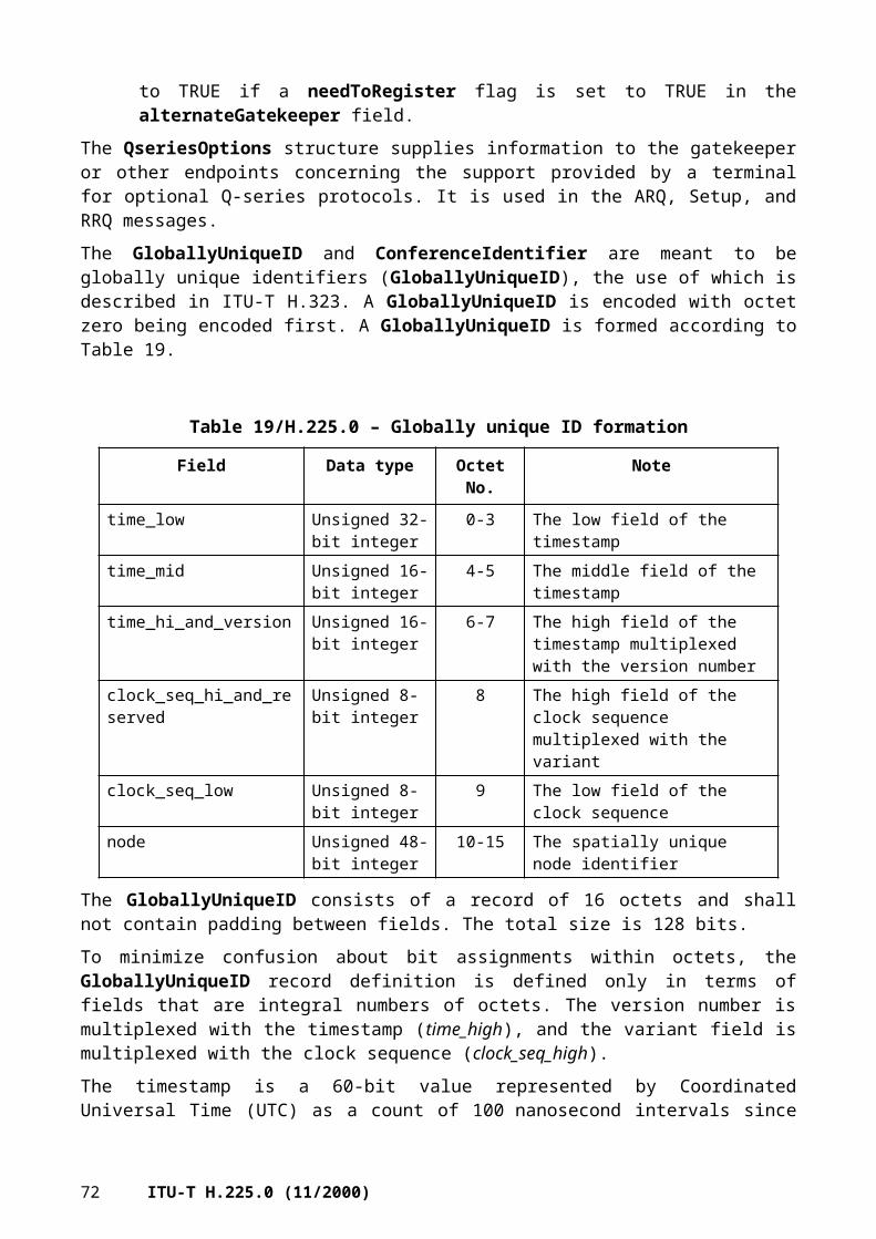
tokens – This is some data which may be required to allow the operation. The data shall be inserted into the message if available.
cryptoTokens – Encrypted tokens.
integrityCheckValue – Provides improved message integrity/message authentication of the RAS messages. The cryptographically based integrity check value is computed by the sender applying a negotiated integrity algorithm and the secret key upon the entire message. Prior to integrityCheckValue computation, this field shall be ignored and shall be empty. After computation, the sender puts the computed integrity check value in the integrityCheckValue field and transmits the message.
featureSet – This field specifies a set of generic features that relate to this call.
genericData – This field is a list of generic elements related to features that are defined outside of the base H.225.0 specification. These parameters may be used, for example, for tunnelling information transparently through RAS.
serviceControl – This field contains addressing information that the endpoint may use for call-related service control communication with the network as described, for example, in Annex K/H.323.
7.14 Disengage messages
7.14.1 DisengageRequest (DRQ)
If sent from an endpoint to a gatekeeper, the DRQ informs the gatekeeper that an endpoint is being dropped. If sent from a gatekeeper to an endpoint, the DRQ forces a call to be dropped; such a request shall not be refused. The DRQ is not sent between endpoints directly.
Note that DRQ is not the same as ReleaseComplete since its purpose is to inform the gatekeeper of the termination of a call; the gatekeeper may not receive the release complete if it is not terminating the call signalling channel.
The DRQ message includes the following:
requestSeqNum – This is a monotonically increasing number unique to the sender. It shall be returned by the receiver in any messages associated with this specific message.
endpointIdentifier – This is an endpoint identifier that was assigned to the terminal by RCF.
conference ID – ID of the call that is to have the bandwidth released.
callReferenceValue – The CRV from Q.931 for this call; only local validity. This is used by a gatekeeper to associate the message with a particular call.
disengageReason – The reason the change was requested by the gatekeeper or the terminal.
nonStandardData – Carries information not defined in this Recommendation (for example, proprietary data).
callIdentifier – A globally unique call identifier set by the originating endpoint which can be used to associate RAS signalling with the modified Q.931 signalling used in this Recommendation.
gatekeeperIdentifier – A gatekeeperIdentifier which the endpoint received in the alternateGatekeeper list in an RCF from the gatekeeper when it registered or in a previous DRJ message.
tokens – This is some data which may be required to allow the operation. The data shall be inserted into the message if available.
cryptoTokens – Encrypted tokens.
ITU-T H.225.0 (11/2000) 75

integrityCheckValue – Provides improved message integrity/message authentication of the RAS messages. The cryptographically based integrity check value is computed by the sender applying a negotiated integrity algorithm and the secret key upon the entire message. Prior to integrityCheckValue computation, this field shall be ignored and shall be empty. After computation, the sender puts the computed integrity check value in the integrityCheckValue field and transmits the message.
answeredCall – Set to TRUE to indicate that this party was the original destination (this party answered the call).
callLinkage – The contents of this field are typically controlled by a call linkage service. For the procedures and semantics of this field, refer to clause 10/H.323.
capacity – This field indicates the sending endpoint's available call capacity at this point in time, assuming that the gatekeeper confirms the DRQ by sending a DCF. When sending this field, the endpoint shall include the currentCallCapacity element. This field is not included when the DRQ is sent by a gatekeeper.
circuitInfo – This field provides information about the SCN circuit or circuits used for this call.
usageInformation – This field allows an endpoint to report usage information for this call. A gatekeeper shall not include this field when sending a DRQ.
terminationCause – This field describes the reason that the call ended. This information is more specific than the reason provided in the disengageReason field. A gatekeeper shall not include this field when sending a DRQ.
serviceControl – This field contains service-specific data, or references to it, that could be used by an endpoint as described, for example, in Annex K/H.323. The gatekeeper could use this field to indicate that the call is ending because some account has expired or the amount paid for the call has been exhausted.
genericData – This field is a list of generic elements related to features that are defined outside of the base H.225.0 specification. These parameters may be used, for example, for tunnelling information transparently through RAS.
7.14.2 DisengageConfirm (DCF)
The DCF message includes the following:
requestSeqNum – This shall be the same value that was passed in the DRQ.
nonStandardData – Carries information not defined in this Recommendation (for example, proprietary data).
tokens – This is some data which may be required to allow the operation. The data shall be inserted into the message if available.
cryptoTokens – Encrypted tokens.
integrityCheckValue – Provides improved message integrity/message authentication of the RAS messages. The cryptographically based integrity check value is computed by the sender applying a negotiated integrity algorithm and the secret key upon the entire message. Prior to integrityCheckValue computation, this field shall be ignored and shall be empty. After computation, the sender puts the computed integrity check value in the integrityCheckValue field and transmits the message.
capacity – This field indicates the sending endpoint's available call capacity after the call indicated in the DCF has been disengaged. When sending this field, the endpoint shall include the currentCallCapacity element. This field is not included when the DCF is sent by a gatekeeper.
circuitInfo – This field provides information about the SCN circuit or circuits used for this call.
76 ITU-T H.225.0 (11/2000)

usageInformation – This field allows an endpoint to report usage information for this call. A gatekeeper shall not include this field when sending a DCF.
genericData – This field is a list of generic elements related to features that are defined outside of the base H.225.0 specification. These parameters may be used, for example, for tunnelling information transparently through RAS.
7.14.3 DisengageReject (DRJ)
DRJ is sent by the gatekeeper if the endpoint is unregistered.
The DRJ message includes the following:
requestSeqNum – This shall be the same value that was passed in the DRQ.
rejectReason – The reason the request was rejected.
nonStandardData – Carries information not defined in this Recommendation (for example, proprietary data).
altGKInfo – Optional information about alternative gatekeepers.
tokens – This is some data which may be required to allow the operation. The data shall be inserted into the message if available.
cryptoTokens – Encrypted tokens.
integrityCheckValue – Provides improved message integrity/message authentication of the RAS messages. The cryptographically based integrity check value is computed by the sender applying a negotiated integrity algorithm and the secret key upon the entire message. Prior to integrityCheckValue computation, this field shall be ignored and shall be empty. After computation, the sender puts the computed integrity check value in the integrityCheckValue field and transmits the message.
genericData – This field is a list of generic elements related to features that are defined outside of the base H.225.0 specification. These parameters may be used, for example, for tunnelling information transparently through RAS.
7.15 Status Request messages
The IRQ is sent from a gatekeeper to a terminal requesting status information in the form of an IRR. The IRR may be also be sent by the terminal at an interval specified in the ACF message without the receipt of an IRQ from the gatekeeper. This message should not be confused with the Q.931 Status message.
When an unsolicited IRR is sent by an endpoint to a gatekeeper of version 2 or higher, it may indicate in the needResponse field that it wishes the gatekeeper to acknowledge receipt of the IRR. In this case it fills in the requestSeqNum field with a number other than 1. The gatekeeper returns either an IACK (positive acknowledgement) or an INAK (negative acknowledgement) message, and shall return the same number in the requestSeqNum field.
7.15.1 InfoRequest (IRQ)
The IRQ message includes the following:
requestSeqNum – This is a monotonically increasing number unique to the sender. It shall be returned by the receiver in any messages associated with this specific message.
ITU-T H.225.0 (11/2000) 77

callReferenceValue – CRV of the call that the query is about. If zero, this message is interpreted as a request for an IRR for each call the terminal is active on. If the terminal is not active on any calls, an IRR shall be sent in response to a callReferenceValue of 0 with all appropriate fields provided. If callReferenceValue is 0, the endpoint shall ignore callIdentifier – in this case the gatekeeper shall fill callIdentifier with 0.
nonStandardData – Carries information not defined in this Recommendation (for example, proprietary data).
replyAddress – A transport address to send IRR to, perhaps not that of the gatekeeper.
callIdentifier – A globally unique call identifier set by the originating endpoint which can be used to associate RAS signalling with the modified Q.931 signalling used in this Recommendation.
tokens – This is some data which may be required to allow the operation. The data shall be inserted into the message if available.
cryptoTokens – Encrypted tokens.
integrityCheckValue – Provides improved message integrity/message authentication of the RAS messages. The cryptographically based integrity check value is computed by the sender applying a negotiated integrity algorithm and the secret key upon the entire message. Prior to integrityCheckValue computation, this field shall be ignored and shall be empty. After computation, the sender puts the computed integrity check value in the integrityCheckValue field and transmits the message.
uuiesRequested – The gatekeeper may request the endpoint to notify the gatekeeper of H.225.0 call signalling messages that the endpoint sends or receives if the endpoint indicated this capability in the ARQ by setting willSupplyUUIEs to TRUE. uuiesRequested indicates the set of H.225.0 call signalling messages of which the endpoint shall notify the gatekeeper.
callLinkage – The contents of this field are typically controlled by a call linkage service. For the procedures and semantics of this field, refer to clause 10/H.323.
usageInfoRequested – This field may be included by a gatekeeper to request that the endpoint report the indicated call usage information in the IRR message.
segmentedResponseSupported – This field indicates whether the gatekeeper will allow the endpoint to return call information for all calls in multiple IRR messages, or "segments". If this field is present, segmentation is allowed. Otherwise, segmentation is not allowed. This field is only significant when the gatekeeper sends an IRQ with a callReferenceValue of 0 and shall not be present otherwise.
nextSegmentRequested – If the gatekeeper sends an IRQ message with callReferenceValue of 0 and includes the segmentedResponseSupported field, the endpoint may return an IRR with only part of the call information, indicated by including the segment field in the IRR. The gatekeeper may request the next segment by retransmitting the previous IRQ message with the nextSegmentRequested field set to the value of the next segment that the gatekeeper expects to receive.
capacityInfoRequested – If present, this field indicates that the gatekeeper is requesting that the endpoint include call capacity information in the IRR.
genericData – This field is a list of generic elements related to features that are defined outside of the base H.225.0 specification. These parameters may be used, for example, for tunnelling information transparently through RAS.
78 ITU-T H.225.0 (11/2000)

7.15.2 InfoRequestResponse (IRR)
The IRR message includes the following:
nonStandardData – Carries information not defined in this Recommendation (for example, proprietary data).
requestSeqNum – In the case of a solicited IRR, this field shall contain the sequence number from the IRQ. In the case of an unsolicited report to a version 1 gatekeeper, this field shall contain one (1). In all other unsolicited IRRs, it shall contain a monotonically increasing number (to be returned by the gatekeeper in its response if needResponse is TRUE).
endpointType – Provides information about the endpoint.
endpointIdentifier – Value assigned by the gatekeeper in the RCF.
rasAddress – Address for registration, admissions, etc.
callSignalAddress – Address of H.225.0 call signalling.
endpointAlias – Alias(es) for endpoint.
perCallInfo – Information about a particular call:• nonStandardData – Carries information not defined in this Recommendation (for example,
proprietary data).• callReferenceValue – Q.931 CRV of that call that the response is about.• conferenceID – Unique conference identifier.• originator – If TRUE the endpoint being queried was the call originator, if FALSE the
endpoint was the call destination.• audio – Information about the audio channel(s). The multicast element shall be included if
the session is multicast.• video – Information about the video channel(s). The multicast element shall be included if
the session is multicast.• data – Information about the data channel(s).• h245 – The transport address of the H.245 control channel.• callSignaling – The transport address of the H.225.0 call signalling channel.• callType – Provides information on call topology.• bandwidth – Current usage in increments of 100 bit/s; includes only audio and video
excluding headers and overhead.• callModel – Indicates the endpoint's idea of which call model is in use.• callIdentifier – A globally unique call identifier set by the originating endpoint which can
be used to associate RAS signalling with the modified Q.931 signalling used in this Recommendation.
• tokens – This is some data which may be required to allow the operation. The data shall be inserted into the message if available.
• cryptoTokens – Encrypted tokens.• substituteConfIDs – A listing of all ConferenceIDs received in H.245 SubstituteCID
messages pertaining to the original RAS perCallInfo conferenceID.• pdu:
– h323pdu – A copy of an H.225.0 and Q.931 PDU as requested by the gatekeeper in uuiesRequested in either ACF or IRQ.
ITU-T H.225.0 (11/2000) 79

– sent – Set to TRUE to indicate the endpoint sent the h323pdu; set to FALSE to indicate the endpoint received the h323pdu.
• callLinkage – The contents of this field are typically controlled by a call linkage service. For the procedures and semantics of this field, refer to clause 10/H.323.
• usageInformation – This field allows the endpoint to report usage information for this call.• circuitInfo – This field provides information about the SCN circuit or circuits used for this
call.
tokens – This is some data which may be required to allow the operation. The data shall be inserted into the message if available.
cryptoTokens – Encrypted tokens.
integrityCheckValue – Provides improved message integrity/message authentication of the RAS messages. The cryptographically based integrity check value is computed by the sender applying a negotiated integrity algorithm and the secret key upon the entire message. Prior to integrityCheckValue computation, this field shall be ignored and shall be empty. After computation, the sender puts the computed integrity check value in the integrityCheckValue field and transmits the message.
needResponse – If this is set to TRUE and the gatekeeper indicated in either RCF or ACF that it will respond to unsolicited IRRs (by setting willRespondToIRR to TRUE), then the gatekeeper shall reply with an IACK or INAK. If the gatekeeper had not indicated in either RCF or ACF that it will respond to unsolicited IRRs (by setting willRespondToIRR to FALSE), then the gatekeeper may ignore the needResponse BOOLEAN.
capacity – Indicates the sending endpoint's call capacity at this point in time. When sending this field, the endpoint shall include the currentCallCapacity element and should only include the maximumCallCapacity when responding to an IRQ that included the capacityInfoRequested element.
irrStatus – This element should be returned in IRR messages in response to an IRQ sent by the gatekeeper. Absence of this element indicates that the IRR message contains complete call detail information. The following values are possible:• complete – Indicates that this IRR contains the last segment of call information for an IRQ
which requests all call details. When segmentation is not used, this field indicates that the IRR contains all of the call details in a single IRR message.
• incomplete – Indicates that the endpoint is not able to fit all of the requested call information in a single IRR message when responding to an IRQ message that contained a callReferenceValue of 0.
• segment – This field indicates the segment number, which is a monotonically increasing value modulo 65536, of this IRR message when segmented IRRs are sent in response to an IRQ containing a callReferenceValue of 0.
• invalidCall – This field indicates that the call referenced in the IRQ message does not exist.
unsolicited – H.323 version 4 and later endpoints shall set this field to TRUE in unsolicited IRR messages as described in 8.4.2/H.323 and shall set it to FALSE it in solicited IRRs.
genericData – This field is a list of generic elements related to features that are defined outside of the base H.225.0 specification. These parameters may be used, for example, for tunnelling information transparently through RAS.
80 ITU-T H.225.0 (11/2000)

7.15.3 InfoRequestAck (IACK)
The IACK message includes the following:
requestSeqNum – This field shall contain the requestSeqNum that was in the IRR.
nonStandardData – Carries information not defined in this Recommendation (for example, proprietary data).
tokens – This is some data which may be required to allow the operation. The data shall be inserted into the message if available.
cryptoTokens – Encrypted tokens.
integrityCheckValue – Provides improved message integrity/message authentication of the RAS messages. The cryptographically based integrity check value is computed by the sender applying a negotiated integrity algorithm and the secret key upon the entire message. Prior to integrityCheckValue computation, this field shall be ignored and shall be empty. After computation, the sender puts the computed integrity check value in the integrityCheckValue field and transmits the message.
7.15.4 InfoRequestNak (INAK)
The INAK message includes the following:
requestSeqNum – This field shall contain the requestSeqNum that was in the IRR.
nonStandardData – Carries information not defined in this Recommendation (for example, proprietary data).
nakReason – Reason the IRR was negatively acknowledged.
altGKInfo – Optional information about alternative gatekeepers.
tokens – This is some data which may be required to allow the operation. The data shall be inserted into the message if available.
cryptoTokens – Encrypted tokens.
integrityCheckValue – Provides improved message integrity/message authentication of the RAS messages. The cryptographically based integrity check value is computed by the sender applying a negotiated integrity algorithm and the secret key upon the entire message. Prior to integrityCheckValue computation, this field shall be ignored and shall be empty. After computation, the sender puts the computed integrity check value in the integrityCheckValue field and transmits the message.
7.16 Non-Standard message
The NonStandardMessage structure is as follows:
requestSeqNum – This is a monotonically increasing number unique to the sender.
nonStandardData – Carries information not defined in this Recommendation (for example, proprietary data).
tokens – This is some data which may be required to allow the operation. The data shall be inserted into the message if available.
cryptoTokens – Encrypted tokens.
integrityCheckValue – Provides improved message integrity/message authentication of the RAS messages. The cryptographically based integrity check value is computed by the sender applying a negotiated integrity algorithm and the secret key upon the entire message. Prior to integrityCheckValue computation, this field shall be ignored and shall be empty. After
ITU-T H.225.0 (11/2000) 81

computation, the sender puts the computed integrity check value in the integrityCheckValue field and transmits the message.
featureSet – This field specifies a set of generic features.
genericData – This field is a list of generic elements related to features that are defined outside of the base H.225.0 specification. These parameters may be used, for example, for tunnelling information transparently through RAS.
7.17 Message Not Understood
This message is sent whenever an H.323 endpoint receives a RAS message it does not understand or it cannot decode. In cases where the destination transport address for the XRS message is not available (i.e. the received RAS message could not be decoded) the XRS may be sent to the transport address from which the not understood RAS message was received. This transport address may be obtained from the underlying transport layer. An XRS message shall not be sent in response to an incoming XRS message. H.323 endpoints should transmit no more than one XRS message per second to the same transport address to avoid network congestion in situations where corrupted messages are received.
RequestSeqNum – Shall be the requestSeqNum of the unknown message, if it can be decoded. If the unknown message cannot be decoded, this field is a monotonically increasing number unique to the sender. The RequestSeqNum should be used for backward compatibility with H.323 version 3 and lower endpoints. H.323 version 4 and higher endpoints should look at the messageNotUnderstood parameter to associate the XRS with a previously transmitted message.
tokens – This is some data which may be required to allow the operation. The data shall be inserted into the message if available.
cryptoTokens – Encrypted tokens.
integrityCheckValue – Provides improved message integrity/message authentication of the RAS messages. The cryptographically based integrity check value is computed by the sender applying a negotiated integrity algorithm and the secret key upon the entire message. Prior to integrityCheckValue computation, this field shall be ignored and shall be empty. After computation, the sender puts the computed integrity check value in the integrityCheckValue field and transmits the message.
messageNotUnderstood – Copy of the message that was received and was not understood.
7.18 Gateway Resource Availability messages
The Resource Availability Indication (RAI) is a notification from a gateway to a gatekeeper of its current call capacity for each H-series protocol and data rate for that protocol. The gatekeeper responds with a Resource Availability Confirmation (RAC) upon receiving a RAI to acknowledge its reception.
7.18.1 ResourcesAvailableIndicate (RAI)
The RAI message includes the following:
requestSeqNum – This is a monotonically increasing number unique to the sender. It shall be returned by the receiver in any response associated with this specific message.
protocolIdentifier – Identifies the vintage of the sending endpoint.
nonStandardData – Carries information not defined in this Recommendation (for example, proprietary data).
endpointIdentifier – A gatekeeper-assigned endpoint identity string.
82 ITU-T H.225.0 (11/2000)

protocols – Indicates the current data rates for each protocol which can be supported given the current state of the device.
almostOutOfResources – When set to TRUE, the device is nearing or at capacity. Any action based on this field is at the manufacturer's discretion. If the device is not near or at capacity this field should be set to FALSE.
tokens – This is some data which may be required to allow the operation. The data shall be inserted into the message if available.
cryptoTokens – Encrypted tokens.
integrityCheckValue – Provides improved message integrity/message authentication of the RAS messages. The cryptographically based integrity check value is computed by the sender applying a negotiated integrity algorithm and the secret key upon the entire message. Prior to integrityCheckValue computation, this field shall be ignored and shall be empty. After computation, the sender puts the computed integrity check value in the integrityCheckValue field and transmits the message.
capacity – Indicates the sending endpoint's call capacity at this point in time. Note that if capacity is provided, the almostOutOfResources BOOLEAN should be ignored by the recipient, since the capacity field provides more detailed information; however, the almostOutOfResources BOOLEAN shall be properly set in order to maintain backward compatibility. When sending the capacity field, the endpoint shall include the currentCallCapacity elements.
genericData – This field is a list of generic elements related to features that are defined outside of the base H.225.0 specification. These parameters may be used, for example, for tunnelling information transparently through RAS.
7.18.2 ResourcesAvailableConfirm (RAC)
The RAC message includes the following:
requestSeqNum – This shall be the same value that was passed in the RAI.
protocolIdentifier – Identifies the vintage of the accepting gatekeeper.
nonStandardData – Carries information not defined in this Recommendation (for example, proprietary data).
tokens – This is some data which may be required to allow the operation. The data shall be inserted into the message if available.
cryptoTokens – Encrypted tokens.
integrityCheckValue – Provides improved message integrity/message authentication of the RAS messages. The cryptographically based integrity check value is computed by the sender applying a negotiated integrity algorithm and the secret key upon the entire message. Prior to integrityCheckValue computation, this field shall be ignored and shall be empty. After computation, the sender puts the computed integrity check value in the integrityCheckValue field and transmits the message.
genericData – This field is a list of generic elements related to features that are defined outside of the base H.225.0 specification. These parameters may be used, for example, for tunnelling information transparently through RAS.
7.19 RAS timers and Request in Progress (RIP)
Table 22 shows recommended default time-out values for the response to RAS messages and subsequent retry counts if a response is not received. (These values are subject to change with further implementation experience and input.)
ITU-T H.225.0 (11/2000) 83

Table 22/H.225.0 – Recommended default time-out values
RAS message Time-out value (s) Retry count
GRQ 5 2RRQ (Note 1) 3 2URQ 3 1ARQ 5 2BRQ 3 2IRQ 3 1IRR (Note 2) 5 2DRQ 3 2LRQ 5 2RAI 3 2SCI 3 2NOTE 1 – The time-out value should be recalculated based upon both the time-to-live (which may be indicated by the gatekeeper in the RCF message) and the desired number of retries.NOTE 2 – In cases where the gatekeeper is expected to reply to an unsolicited IRR with IACK or INAK, the time-out may occur if no reply to the IRR is received.
If an entity receives a request from a version 2 (or later) entity to which a response cannot be generated within a typical retry time-out period, it can send a RIP message specifying the period (in the delay field) after which a response should have been generated. As soon as a response is available, the responding entity should send the response and not wait for the RIP delay to expire. If a requesting entity has not received a response by the time the RIP delay expires, it shall resend the request. The responding entity can then either send a duplicate response or another RIP message. Figure 2 gives an example message exchange which demonstrates a number of aspects of the retry strategy.
Vendors should be aware that any retries will have an impact on the call setup time, which should be minimized. Therefore short retry times are desirable. So that remote entities can anticipate typical retry times for the purpose of deciding when to send a RIP message, entities should avoid retry periods less than 100 ms. Exponential backoff and adapting to measured round-trip times is encouraged. Entities can use the measured round trip time of the RRQ/RCF registration process to modify an initially conservative estimate (of a few seconds) for this purpose. Entities may also use the registration process to exchange version numbers to ensure that the RIP-based retry mechanism is not used when version 1 entities are involved in the signalling.
84 ITU-T H.225.0 (11/2000)

Figure 2/H.225.0 – Example Use of RIP message
The RIP message includes the following:
requestSeqNum – This is the requestSeqNum of the request which is currently being processed.
nonStandardData – Carries information not defined in this Recommendation (for example, proprietary data).
tokens – This is some data which may be required to allow the operation. The data shall be inserted into the message if available.
cryptoTokens – Encrypted tokens.
integrityCheckValue – Provides improved message integrity/message authentication of the RAS messages. The cryptographically based integrity check value is computed by the sender applying a negotiated integrity algorithm and the secret key upon the entire message. Prior to integrityCheckValue computation, this field shall be ignored and shall be empty. After computation, the sender puts the computed integrity check value in the integrityCheckValue field and transmits the message.
delay – Specifies the amount of time in milliseconds that an endpoint shall wait before attempting a retry. The responding endpoint may respond before this period expires.
7.20 Service Control messages
7.20.1 ServiceControlIndication (SCI)
The SCI message is sent from a service provider to indicate to the service client that a separate service control session may be initiated towards the given address. It may be sent from a gatekeeper to an endpoint (e.g. for user presentation of service features) or from an endpoint to a gatekeeper (e.g. to upload a call processing script). Note that H.323 entities of version 3 or earlier are not able to decode this message and thus will not answer.
The SCI message contains the following:
requestSeqNum – This is a monotonically increasing number unique to the sender. It shall be returned by the receiver in any response associated with this specific message.
ITU-T H.225.0 (11/2000) 85

nonStandardData – Carries information not defined in this Recommendation (for example, proprietary data).
serviceControl – Carries a set of service control session information.
endpointIdentifier Set to the value received from the gatekeeper in the RCF message if the message is sent from an endpoint to its gatekeeper.
callSpecific Provided if the sessions given are relating to one specific call. The callIdentifier, conferenceID and answeredCall shall be set to the same value as in the ARQ message the service session is relating to.
tokens – This is some data which may be required to allow the operation. The data shall be inserted into the message if available.
cryptoTokens – Encrypted tokens.
integrityCheckValue – Provides improved message integrity/message authentication of the RAS messages. The cryptographically based integrity check value is computed by the sender applying a negotiated integrity algorithm and the secret key upon the entire message. Prior to integrityCheckValue computation, this field shall be ignored and shall be empty. After computation, the sender puts the computed integrity check value in the integrityCheckValue field and transmits the message.
featureSet – This field specifies a set of generic features.
genericData – This field is a list of generic elements related to features that are defined outside of the base H.225.0 specification. These parameters may be used, for example, for tunnelling information transparently through RAS.
7.20.2 ServiceControlResponse (SCR)
The SCR message is sent to acknowledge the receipt of an SCI message, but does not necessarily mean that the service client will initiate the session as given in SCI.
The SCR message contains the following:
requestSeqNum – This shall be the same value that was passed in the SCI.
result – This field indicates the result of processing the information contained in the SCI message. The following values are defined:• started – The requested service control was started.• failed – There was some error with the request, so the request failed.• stopped – The service control was stopped.• notAvailable – The requested service control was not available at the time of the request.
nonStandardData – Carries information not defined in this Recommendation (for example, proprietary data).
tokens – This is some data which may be required to allow the operation. The data shall be inserted into the message if available.
cryptoTokens – Encrypted tokens.
integrityCheckValue – Provides improved message integrity/message authentication of the RAS messages. The cryptographically based integrity check value is computed by the sender applying a negotiated integrity algorithm and the secret key upon the entire message. Prior to integrityCheckValue computation, this field shall be ignored and shall be empty. After computation, the sender puts the computed integrity check value in the integrityCheckValue field and transmits the message.
86 ITU-T H.225.0 (11/2000)

featureSet – This field specifies a set of generic features.
genericData – This field is a list of generic elements related to features that are defined outside of the base H.225.0 specification. These parameters may be used, for example, for tunnelling information transparently through RAS.
8 Mechanisms for maintaining QOS
8.1 General approach and assumptions
Transport QOS (Quality of Service) on a packet-based network includes such characteristics as:• bit error rate;• packet loss rate;• delay.
Any transport QOS-related signalling (e.g. a reservation request to a router) is done by the terminal as soon as possible, or by the gatekeeper on its behalf. The terminal may wish to make any reservations since the gatekeeper may not be logically near the terminal, or be able to make QOS related requests on behalf of the terminal. The means by which either the terminal or the gatekeeper make QOS or bandwidth reservations are beyond the scope of this Recommendation.
The Sender and Receiver Reports of RTCP shall be the means by which QOS will be assessed.
There are two types of congestion-related delay that might be measured:• short-term increases in delay that will result in a perceptible but not annoying slowing of the
frame rate;• a general rise in delay due to packet-based network congestion over time such that a
feedback-based mechanism is useful.
Essentially, short-term bursts are approached by error concealment, and a longer term congestion is approached by reducing the multimedia load. The assumption is made that all packet-based network multimedia terminals are H.323 terminals, and all will attempt to reduce packet-based network usage as congestion rises rather than "steal" bandwidth from each other.
Bit errors on a packet-based network generally are either corrected at a lower layer, or result in packet loss, so they are not considered further in this clause.
Packet loss requires the receiver to be able to compensate for lost packets in a fashion that conceals errors to the maximum possible extent. For data and control, retransmission at the transport layer is used. For audio and video, retransmission is for further study.
A given level of transport QOS results in a level of user-perceived audio/video QOS that is a function in part of the effectiveness of the methods used to overcome transport QOS problems.
8.2 Use of RTCP in measuring QOS
8.2.1 Sender reports
The sender report serves three main purposes:1) allow synchronization of multiple RTP streams, such as audio and video;2) allow the receiver to know the expected data rate and packet rate;3) allow the receiver to measure the distance in time to the sender.
Of these three purposes, 1) is the most relevant to this Recommendation. Manufacturers may make use of the sender reports in other ways at their discretion.
ITU-T H.225.0 (11/2000) 87

The relevant field for stream synchronization is the RTP timestamp and the NTP timestamp in the sender report of RTCP. The NTP timestamp (if available) gives "wall clock" time and corresponds to the RTP timestamp which has the same units and random offset as the RTP capture timestamp in the media packets.
8.2.2 Receiver Reports
Four parts of the Receiver Reports are used in this Recommendation to measure QOS:1) fraction lost;2) the cumulative packets lost;3) the extended highest sequence number received;4) interarrival jitter.
Items 2) and 3) are used to compute the number of packets lost since the previous receiver report. This can be taken as a long-term measure of packet-based network congestion. See A.6.3.4 for a sample computation. If this loss rate exceeds a value set by the manufacturer, the H.225.0 terminal should reduce the media rates on the packet-based network side according to the procedures in 8.4 below. If item 1) exceeds a value set by the manufacturer, it may also be desirable to take corrective action.
If the interval between receiver reports exceeds a value set by the manufacturer, H.323 terminals should use item 1) as an indicator of serious congestion requiring media rate reduction on the packet-based network side.
Item 4) should be used as an indication of impending congestion. If interarrival jitter increases for three consecutive receiver reports, the H.323 sending terminal should take corrective action.
8.3 Audio/Video jitter procedures
ITU-T H.245 provides commands and procedures for round-trip indications using RoundTripDelayRequest and RoundTripDelayResponse. On a multipoint call the MC responds to a request from the endpoint. RTCP contains a method of calculating round-trip delays based on the Sender Report and the Receiver Report messages. Note that the quantity being measured in each case is not the same, so there is no conflict in using both methods to measure jitter.
See 6.2.5/H.323 for a discussion of how H.245 level signalling can be used to optionally reduce jitter related delays.
8.4 Audio/Video skew procedures
See 6.2.6/H.323 for a discussion of how H.245 level signalling is used to limit the skew between different logical channels.
8.5 Procedures for maintaining QOS
A number of methods exist for the H.323 gateway/terminal to respond to an increase in packet loss or interarrival jitter in the far-end receiver. These methods can be grouped into those that are appropriate for a rapid response to a short-term problem, such as a lost or delayed packet, and those that are appropriate for a response to a longer-term problem such as growing congestion on the packet-based network. Note that these methods do not seek to maintain the current quality of service, but instead to provide for an orderly degradation of service. The following priorities shall be observed such that, if present, media shall be degraded in the following order: Video, Data, Audio, Control.
88 ITU-T H.225.0 (11/2000)

Short-term responses:• reducing the frame rate for a short period of time: This may result in the H.323 gateway
sending additional H.261 fill frames in the packet-based network to SCN direction to compensate for the packet under flow;
• reduce packet rate by switching to the optional mode where audio/video are mixed in one packet (for further study);
• packet rate can also be reduced via the use of MB fragmentation of the video stream.
Longer-term responses:• reducing media bit rate (e.g. switching from 384 kbit/s to 256 kbit/s): This may involve a
simple instruction to the encoder in a terminal, or it may involve the use of a rate reducer function in the H.323 gateway. These changes are signalled via H.245 FlowControl commands, or by logical channel signalling as appropriate;
• turning off media of lesser importance (e.g. turning off video to allow a large amount of T.120 traffic);
• returning a busy signal (adaptive busy) to the receiver as an indication of packet-based network congestion. This may be combined with turning off a media, or even all media other than the control Transport Port. Adaptive busy is signalled via a Q.931 cause value in Release Complete.
It should be noted that responding to interarrival jitter in a multi-router path where a large percentage of packets arrive out of order is difficult. It may be impossible to distinguish this source of jitter from other sources, or to base error recovery strategy on measured jitter. However, packet loss is quantifiable and unambiguous.
8.6 Echo control
Control of acoustic echo is the responsibility of the H-series terminal. In general, given the delay involved in video/audio compression, it is assumed that all H.320, H.323 and H.324 terminals have some form of echo control (cancellation or switching).
However, when the H.323 terminal is on a call with a GSTN telephone, it is typically the case that the GSTN phone does not support echo control. Thus, the user of the H.323 terminal may hear acoustic echo return from the GSTN side. This acoustic echo return can be minimized by the use of a speakerphone with echo control, or the use of a handset or ear phones. Manufacturers may add loss to the audio path when an H.323 terminal is connected to a GSTN POTS phone.
Control of hybrid (2- to 4-wire) echo. The hybrid circuit provides an interface between 4-wire transmission systems and 2-wire terminals. For ISDN speech calls that are carried through the GSTN at 64 kbit/s, echo cancellation is not required. For 64 kbit/s data calls, echo cancellation is not permitted.
In the case of a decomposed gateway interfacing to an SS7 network, indications of the provision of echo cancellation are carried in the ISUP signalling message, as specified in ITU-T Q.115. The H.323 media gateway controller (MGC) can interpret the signalling information and either enable or disable echo cancellation at the media gateway (MG). For speech calls the MGC can enable echo cancellation without deleterious effects on speech quality even if the GSTN has provided echo cancellation in the GSTN.
For voiceband data calls (modem calls) that transit or terminate on an H.323 network, control of echo cancellation is provided by the modems by in-band tones. No out-of-band signalling is required by the GSTN network elements or by the MGCs.
ITU-T H.225.0 (11/2000) 89
ANNEX A
RTP/RTCP
The reader should note that all references in this annex are to a bibliography, and are non-normative, with the exception of [A-10] to ISO/IEC 10646-1, which also appears in the references clause of this Recommendation. In some cases a reference will appear to Appendix I; such references are for informative purposes only. All details required to implement ITU-T H.323 and this Recommendation are contained in this annex and other related annexes and Recommendations or International Standards published by the ITU-T or the ISO.
Readers should note that this annex is not the complete and primary specification of RTP/RTCP; please refer to Appendix I for this informative reference. This annex is intended only for usage with ITU-T H.323 and this Recommendation.
Readers should also note that the terminology used in this annex differs somewhat from that used in ITU-T H.323 and this Recommendation according to Table A.1.
Table A.1/H.225.0 – Terminology correspondence
H.323 and H.225.0 term Annex A (RTP/RTCP) term
media stream datatransport address transport addresspacket-based network address network addressTSAP identifier portAnnex A specification or documentshall mustshould should
It should be further noted that "translators" and "mixers" are not part of the H.323 system. H.323 endpoints such as gateways and MCUs have some of the characteristics of translators and mixers, so this text has been retained as a guide to the implementor. However, support for translators and mixers is not part of H.323, and these subclauses shall be considered informative.
Finally, implementors are reminded to implement RTP only as described in this Recommendation, including Annexes A, B, and C, which contain details and clarifications relevant to H.323/H.225.0. In all cases, the text of this Recommendation shall have precedence over text in this annex and in Annexes B or C.
A.1 Introduction
This annex specifies the Real-Time Transport protocol (RTP), which provides end-to-end delivery services for data with real-time characteristics, such as interactive audio and video. Those services include payload type identification, sequence numbering, timestamping and delivery monitoring. Applications typically run RTP on top of UDP to make use of its multiplexing and checksum services; both protocols contribute parts of the transport protocol functionality. However, RTP may be used with other suitable underlying network or transport protocols (see A.10, RTP over Network and Transport Protocols). RTP supports data transfer to multiple destinations using multicast distribution if provided by the underlying network.
90 ITU-T H.225.0 (11/2000)
Note that RTP itself does not provide any mechanism to ensure timely delivery or provide other quality-of-service guarantees, but relies on lower-layer services to do so. It does not guarantee delivery or prevent out-of-order delivery, nor does it assume that the underlying network is reliable and delivers packets in sequence. The sequence numbers included in RTP allow the receiver to reconstruct the sender's packet sequence, but sequence numbers might also be used to determine the proper location of a packet, for example in video decoding, without necessarily decoding packets in sequence.
While RTP is primarily designed to satisfy the needs of multi-participant multimedia conferences, it is not limited to that particular application. Storage of continuous data, interactive distributed simulation, active badge, and control and measurement applications may also find RTP applicable.
This Recommendation defines RTP, consisting of two closely-linked parts:• the Real-Time Transport (RTP) protocol, to carry data that has real-time properties;• the RTP Control Protocol (RTCP), to monitor the quality of service and to convey
information about the participants in an on-going session. The latter aspect of RTCP may be sufficient for "loosely controlled" sessions, i.e. where there is no explicit membership control and setup, but it is not necessarily intended to support all of an application's control communication requirements. This functionality may be fully or partially subsumed by a separate session control protocol, which is beyond the scope of this Recommendation.
RTP represents a new style of protocol following the principles of application level framing and integrated layer processing proposed by Clark and Tennenhouse [A-1]. That is, RTP is intended to be malleable to provide the information required by a particular application and will often be integrated into the application processing rather than being implemented as a separate layer. RTP is a protocol framework that is deliberately not complete. This Recommendation specifies those functions expected to be common across all the applications for which RTP would be appropriate. Unlike conventional protocols in which additional functions might be accommodated by making the protocol more general or by adding an option mechanism that would require parsing, RTP is intended to be tailored through modifications and/or additions to the headers as needed. Examples are given in A.5.3, Profile-specific modifications to the RTP header.
Therefore, in addition to this Recommendation, a complete specification of RTP for a particular application will require one or more companion documents (see Annexes B and C):• A profile specification document, which defines a set of payload type codes and their
mapping to payload formats (e.g. media encodings). A profile may also define extensions or modifications to RTP that are specific to a particular class of applications. Typically an application will operate under only one profile. A profile for audio and video data may be found in Annex B.
• Payload format specification documents, which define how a particular payload, such as an audio or video encoding, is to be carried in RTP. See Annex C.
Several RTP applications, both experimental and commercial, have already been implemented from draft specifications. These applications include audio and video tools along with diagnostic tools such as traffic monitors. Users of these tools number in the thousands. However, the current Internet cannot yet support the full potential demand for real-time services. High-bandwidth services using RTP, such as video, can potentially seriously degrade the quality of service of other network services. Thus, implementors should take appropriate precautions to limit accidental bandwidth usage. Application documentation should clearly outline the limitations and possible operational impact of high-bandwidth real-time services on the Internet and other network services.
ITU-T H.225.0 (11/2000) 91

A.2 RTP use scenarios
The following subclauses describe some aspects of the use of RTP. The examples were chosen to illustrate the basic operation of applications using RTP, not to limit what RTP may be used for. In these examples, RTP is carried on top of IP and UDP, and follows the conventions established by the profile for audio and video specified in Annex B.
A.2.1 Simple multicast audio conference
A working group of the IETF meets to discuss the latest protocol draft, using the IP multicast services of the Internet for voice communications. Through some allocation mechanism, the working group chair obtains a multicast group address and a pair of ports. One port is used for audio data, and the other is used for control (RTCP) packets. This address and port information is distributed to the intended participants. If privacy is desired, the data and control packets may be encrypted as specified in ITU-T H.323. The audio conferencing application used by each conference participant sends audio data in small chunks of, say, 20 ms duration. Each chunk of audio data is preceded by an RTP header; RTP header and data are in turn contained in a UDP packet. The RTP header indicates what type of audio encoding (such as PCM, ADPCM or LPC) is contained in each packet so that senders can change the encoding during a conference, for example, to accommodate a new participant that is connected through a low-bandwidth link or react to indications of network congestion.
The Internet, like other packet networks, occasionally loses and reorders packets and delays them by variable amounts of time. To cope with these impairments, the RTP header contains timing information and a sequence number that allow the receivers to reconstruct the timing produced by the source, so that in this example, chunks of audio are contiguously played out the speaker every 20 ms. This timing reconstruction is performed separately for each source of RTP packets in the conference. The sequence number can also be used by the receiver to estimate how many packets are being lost.
Since members of the working group join and leave during the conference, it is useful to know who is participating at any moment and how well they are receiving the audio data. For that purpose, each instance of the audio application in the conference periodically multicasts a reception report plus the name of its user on the RTCP (control) port. The reception report indicates how well the current speaker is being received and may be used to control adaptive encodings. In addition to the user name, other identifying information may also be included subject to control bandwidth limits. A site sends the RTCP BYE packet (see A.6.5, BYE: Goodbye RTCP packet) when it leaves the conference.
A.2.2 Audio and video conference
If both audio and video media are used in a conference, they are transmitted as separate RTP sessions; RTCP packets are transmitted for each medium using two different UDP port pairs and/or multicast addresses. There is no direct coupling at the RTP level between the audio and video sessions, except that a user participating in both sessions should use the same distinguished (canonical) name in the RTCP packets for both so that the sessions can be associated.
One motivation for this separation is to allow some participants in the conference to receive only one medium if they choose. Further explanation is given in A.5.2, Multiplexing RTP sessions. Despite the separation, synchronized playback of a source's audio and video can be achieved using timing information carried in the RTCP packets for both sessions.
92 ITU-T H.225.0 (11/2000)

A.2.3 Mixers and translators
So far, we have assumed that all sites want to receive media data in the same format. However, this may not always be appropriate. Consider the case where participants in one area are connected through a low-speed link to the majority of the conference participants who enjoy high-speed network access. Instead of forcing everyone to use a lower-bandwidth, reduced-quality audio encoding, an RTP-level relay, called a mixer, may be placed near the low-bandwidth area. This mixer resynchronizes incoming audio packets to reconstruct the constant 20 ms spacing generated by the sender, mixes these reconstructed audio streams into a single stream, translates the audio encoding to a lower bandwidth one, and forwards the lower bandwidth packet stream across the low-speed link. These packets might be unicast to a single recipient or multicast on a different address to multiple recipients. The RTP header includes a means for mixers to identify the sources that contributed to a mixed packet so that correct talker indication can be provided at the receivers.
Some of the intended participants in the audio conference may be connected with high bandwidth links but might not be directly reachable via IP multicast. For example, they might be behind an application-level firewall that will not let any IP packet pass. For these sites, mixing may not be necessary, in which case another type of RTP-level relay called a "translator" may be used. Two translators are installed, one on either side of the firewall, with the outside one funnelling all multicast packets received through a secure connection to the translator inside the firewall. The translator inside the firewall sends them again as multicast packets to a multicast group restricted to the site's internal network.
Mixers and translators may be designed for a variety of purposes. An example is a video mixer that scales the images of individual people in separate video streams and composites them into one video stream to simulate a group scene. Other examples of translation include the connection of a group of hosts speaking only IP/UDP to a group of hosts that understand only ST-II, or the packet-by-packet encoding translation of video streams from individual sources without resynchronization or mixing. Details of the operation of mixers and translators are given in A.7, RTP translators and mixers.
A.3 Definitions
This annex defines the following terms:
A.3.1 RTP payload: The data transported by RTP in a packet, for example audio samples or compressed video data. The payload format and interpretation are beyond the scope of this Recommendation.
A.3.2 RTP packet: A data packet consisting of the fixed RTP header, a possibly empty list of contributing sources (see below), and the payload data. Some underlying protocols may require an encapsulation of the RTP packet to be defined. Typically, one packet of the underlying protocol contains a single RTP packet, but several RTP packets may be contained if permitted by the encapsulation method (see A.10, RTP over network and transport protocols).
A.3.3 RTCP packet: A control packet consisting of a fixed header part similar to that of RTP data packets, followed by structured elements that vary depending upon the RTCP packet type. The formats are defined in A.6, RTP Control Protocol – RTCP. Typically, multiple RTCP packets are sent together as a compound RTCP packet in a single packet of the underlying protocol; this is enabled by the length field in the fixed header of each RTCP packet.
A.3.4 port: The "abstraction that transport protocols use to distinguish among multiple destinations within a given host computer. TCP/IP protocols identify ports using small positive integers" [A-2]. The Transport Selectors (TSEL) used by the OSI transport layer are equivalent to ports. RTP depends upon the lower-layer protocol to provide some mechanism such as ports to multiplex the RTP and RTCP packets of a session.
ITU-T H.225.0 (11/2000) 93

A.3.5 transport address: The combination of a network address and port that identifies a transport-level endpoint, for example an IP address and a UDP port. Packets are transmitted from a source transport address to a destination transport address.
A.3.6 RTP session: The association among a set of participants communicating with RTP. For each participant, the session is defined by a particular pair of destination transport addresses (one network address plus a port pair for RTP and RTCP). The destination transport address pair may be common for all participants, as in the case of IP multicast, or may be different for each, as in the case of individual unicast network addresses and ports. In a multimedia session, each medium is carried in a separate RTP session with its own RTCP packets. The multiple RTP sessions are distinguished by different port number pairs and/or different multicast addresses.
A.3.7 synchronization source (SSRC): The source of a stream of RTP packets, identified by a 32-bit numeric SSRC identifier carried in the RTP header so as not to be dependent upon the network address. All packets from a synchronization source form part of the same timing and sequence number space, so a receiver group packets by synchronization source for playback. Examples of synchronization sources include the sender of a stream of packets derived from a signal source such as a microphone or a camera, or an RTP mixer (see below). A synchronization source may change its data format, e.g. audio encoding, over time. The SSRC identifier is a randomly chosen value meant to be globally unique within a particular RTP session (see A.8, SSRC identifier allocation and use). A participant need not use the same SSRC identifier for all the RTP sessions in a multimedia session; the binding of the SSRC identifiers is provided through RTCP (see A.6.4.1, CNAME: Canonical end-point identifier SDES item). If a participant generates multiple streams in one RTP session, for example from separate video cameras, each must be identified as a different SSRC.
A.3.8 contributing source (CSRC): A source of a stream of RTP packets that has contributed to the combined stream produced by an RTP mixer (see below). The mixer inserts a list of the SSRC identifiers of the sources that contributed to the generation of a particular packet into the RTP header of that packet. This list is called the CSRC list. An example application is audio conferencing where a mixer indicates all the talkers whose speech was combined to produce the outgoing packet, allowing the receiver to indicate the current talker, even though all the audio packets contain the same SSRC identifier (that of the mixer).
A.3.9 end system: An application that generates the content to be sent in RTP packets and/or consumes the content of received RTP packets. An end system can act as one or more synchronization sources in a particular RTP session, but typically only one.
A.3.10 mixer: An intermediate system that receives RTP packets from one or more sources, possibly changes the data format, combines the packets in some manner and then forwards a new RTP packet. Since the timing among multiple input sources will not generally be synchronized, the mixer will make timing adjustments among the streams and generate its own timing for the combined stream. Thus, all data packets originating from a mixer will be identified as having the mixer as their synchronization source.
A.3.11 translator: An intermediate system that forwards RTP packets with their synchronization source identifier intact. Examples of translators include devices that convert encodings without mixing, replicators from multicast to unicast, and application-level filters in firewalls.
A.3.12 monitor: An application that receives RTCP packets sent by participants in an RTP session, in particular the reception reports, and estimates the current quality of service for distribution monitoring, fault diagnosis and long-term statistics. The monitor function is likely to be built into the application(s) participating in the session, but may also be a separate application that does not otherwise participate and does not send or receive the RTP data packets. These are called third-party monitors.
94 ITU-T H.225.0 (11/2000)

A.3.13 non-RTP means: Protocols and mechanisms that may be needed in addition to RTP to provide a usable service. In particular, for multimedia conferences, a conference control application may distribute multicast addresses and keys for encryption, negotiate the encryption algorithm to be used, and define dynamic mappings between RTP payload type values and the payload formats they represent for formats that do not have a predefined payload type value. For simple applications, electronic mail or a conference database may also be used. The specification of such protocols and mechanisms is outside the scope of this Recommendation.
A.4 Byte order, alignment and time format
All integer fields are carried in network byte order, that is, most significant byte (octet) first. This byte order is commonly known as big-endian. The transmission order is described in detail in [A-3]. Unless otherwise noted, numeric constants are in decimal (base 10).
All header data is aligned to its natural length, i.e. 16-bit fields are aligned on even offsets, 32-bit fields are aligned at offsets divisible by four, etc. Octets designated as padding have the value zero.
Wallclock time (absolute time) is represented using the timestamp format of the Network Time Protocol (NTP), which is in seconds relative to 0h UTC on 1 January 1900 [A-4]. The full resolution NTP timestamp is a 64-bit unsigned fixed-point number with the integer part in the first 32 bits and the fractional part in the last 32 bits. In some fields where a more compact representation is appropriate, only the middle 32 bits are used: that is, the low 16 bits of the integer part and the high 16 bits of the fractional part. The high 16 bits of the integer part must be determined independently.
A.5 RTP data transfer protocol
A.5.1 RTP fixed header fields
The RTP header has the following format:
The first twelve octets are present in every RTP packet, while the list of CSRC identifiers is present only when inserted by a mixer. The fields have the following meaning:
version (V): 2 bits. This field identifies the version of RTP. The version defined by this Recommendation is two (2). (The value 1 is used by the first draft version of RTP and the value 0 is used by the protocol initially implemented in the "vat" audio tool.)
padding (P): 1 bit. If the padding bit is set, the packet contains one or more additional padding octets at the end which are not part of the payload. The last octet of the padding contains a count of how many padding octets should be ignored. Padding may be needed by some encryption algorithms with fixed block sizes or for carrying several RTP packets in a lower-layer protocol data unit.
ITU-T H.225.0 (11/2000) 95

extension (X): 1 bit. If the extension bit is set, the fixed header is followed by exactly one header extension, with a format defined in A.5.3, Profile-specific modifications to the RTP header.
CSRC count (CC): 4 bits. The CSRC count contains the number of CSRC identifiers that follow the fixed header.
marker (M): 1 bit. The interpretation of the marker is defined by a profile. It is intended to allow significant events such as frame boundaries to be marked in the packet stream. A profile may define additional marker bits or specify that there is no marker bit by changing the number of bits in the payload type field (see A.5.3, Profile-specific modifications to the RTP header).
payload type (PT): 7 bits. This field identifies the format of the RTP payload and determines its interpretation by the application. A profile specifies a default static mapping of payload type codes to payload formats. Additional payload type codes may be defined dynamically through non-RTP means (see A.3, Definitions). An initial set of default mappings for audio and video is specified in Annex B. An RTP sender emits a single RTP payload type at any given time; this field is not intended for multiplexing separate media streams (see A.5.2, Multiplexing RTP sessions).
sequence number: 16 bits. The sequence number increments by one for each RTP data packet sent, and may be used by the receiver to detect packet loss and to restore packet sequence. The initial value of the sequence number is random (unpredictable) to make known-plaintext attacks on encryption more difficult, even if the source itself does not encrypt, because the packets may flow through a translator that does. Techniques for choosing unpredictable numbers are discussed in [A-5].
timestamp: 32 bits. The timestamp reflects the sampling instant of the first octet in the RTP data packet. The sampling instant must be derived from a clock that increments monotonically and linearly in time to allow synchronization and jitter calculations (see A.6.3.1, SR: Sender Report RTCP packet). The resolution of the clock must be sufficient for the desired synchronization accuracy and for measuring packet arrival jitter (one tick per video frame is typically not sufficient). The clock frequency is dependent on the format of data carried as payload and is specified statically in the profile or payload format specification that defines the format, or may be specified dynamically for payload formats defined through non-RTP means. If RTP packets are generated periodically, the nominal sampling instant as determined from the sampling clock is to be used, not a reading of the system clock. As an example, for fixed-rate audio the timestamp clock would likely increment by one for each sampling period. If an audio application reads blocks covering 160 sampling periods from the input device, the timestamp would be increased by 160 for each such block, regardless of whether the block is transmitted in a packet or dropped as silent.
The initial value of the timestamp is random, as for the sequence number. Several consecutive RTP packets may have equal timestamps if they are (logically) generated at once, e.g. if they belong to the same video frame. Consecutive RTP packets may contain timestamps that are not monotonic if the data is not transmitted in the order it was sampled, as in the case of MPEG interpolated video frames. (The sequence numbers of the packets as transmitted will still be monotonic.)
SSRC: 32 bits. The SSRC field identifies the synchronization source. This identifier is chosen randomly, with the intent that no two synchronization sources within the same RTP session will have the same SSRC identifier. An example algorithm for generating a random identifier is presented in I.6. Although the probability of multiple sources choosing the same identifier is low, all RTP implementations must be prepared to detect and resolve collisions. Clause A.8, SSRC identifier allocation and use, describes the probability of collision along with a mechanism for resolving collisions and detecting RTP-level forwarding loops based on the uniqueness of the SSRC identifier. If a source changes its source transport address, it must also choose a new SSRC identifier to avoid being interpreted as a looped source.
96 ITU-T H.225.0 (11/2000)

CSRC list: 0 to 15 items, 32 bits each. The CSRC list identifies the contributing sources for the payload contained in this packet. The number of identifiers is given by the CC field. If there are more than 15 contributing sources, only 15 may be identified. CSRC identifiers are inserted by mixers, using the SSRC identifiers of contributing sources. For example, for audio packets the SSRC identifiers of all sources that were mixed together to create a packet are listed, allowing correct talker indication at the receiver.
A.5.2 Multiplexing RTP sessions
For efficient protocol processing, the number of multiplexing points should be minimized, as described in the integrated layer processing design principle [A-1]. In RTP, multiplexing is provided by the destination transport address (network address and port number) which define an RTP session. For example, in a teleconference composed of audio and video media encoded separately, each medium should be carried in a separate RTP session with its own destination transport address. It is not intended that the audio and video be carried in a single RTP session and demultiplexed based on the payload type or SSRC fields. Interleaving packets with different payload types but using the same SSRC would introduce several problems: 1) If one payload type were switched during a session, there would be no general means to
identify which of the old values the new one replaced. 2) An SSRC is defined to identify a single timing and sequence number space. Interleaving
multiple payload types would require different timing spaces if the media clock rates differ and would require different sequence number spaces to tell which payload type suffered packet loss.
3) The RTCP sender and receiver reports (see A.6.3, Sender and receiver reports) can only describe one timing and sequence number space per SSRC and do not carry a payload type field.
4) An RTP mixer would not be able to combine interleaved streams of incompatible media into one stream.
5) Carrying multiple media in one RTP session precludes: the use of different network paths or network resource allocations if appropriate; reception of a subset of the media if desired, for example just audio if video would
exceed the available bandwidth; and receiver implementations that use separate processes for the different media, whereas using separate RTP sessions permits either single- or multiple-process implementations.
Using a different SSRC for each medium but sending them in the same RTP session would avoid the first three problems but not the last two.
A.5.3 Profile-specific modifications to the RTP header
The existing RTP data packet header is believed to be complete for the set of functions required in common across all the application classes that RTP might support. However, in keeping with the ALF design principle, the header may be tailored through modifications or additions defined in a profile specification while still allowing profile-independent monitoring and recording tools to function: • The marker bit and payload type field carry profile-specific information, but they are
allocated in the fixed header since many applications are expected to need them and might otherwise have to add another 32-bit word just to hold them. The octet containing these fields may be redefined by a profile to suit different requirements, for example with more or fewer marker bits. If there are any marker bits, one should be located in the most significant
ITU-T H.225.0 (11/2000) 97

bit of the octet since profile-independent monitors may be able to observe a correlation between packet loss patterns and the marker bit.
• Additional information that is required for a particular payload format, such as a video encoding, should be carried in the payload section of the packet. This might be in a header that is always present at the start of the payload section, or might be indicated by a reserved value in the data pattern.
• If a particular class of applications needs additional functionality independent of payload format, the profile, under which those applications operate, should define additional fixed fields to follow immediately after the SSRC field of the existing fixed header. Those applications will be able to quickly and directly access the additional fields while profile-independent monitors or recorders can still process the RTP packets by interpreting only the first twelve octets.
If it turns out that additional functionality is needed in common across all profiles, then a new version of RTP should be defined to make a permanent change to the fixed header.
A.5.3.1 RTP header extension
An extension mechanism is provided to allow individual implementations to experiment with new payload-format-independent functions that require additional information to be carried in the RTP data packet header. This mechanism is designed so that the header extension may be ignored by other interoperating implementations that have not been extended.
Note that this header extension is intended only for limited use. Most potential uses of this mechanism would be better done another way, using the methods described in the previous clause. For example, a profile-specific extension to the fixed header is less expensive to process because it is not conditional nor it is in a variable location. Additional information required for a particular payload format should not use this header extension, but should be carried in the payload section of the packet:
If the X bit in the RTP header is one, a variable-length header extension is appended to the RTP header, following the CSRC list if present. The header extension contains a 16-bit length field that counts the number of 32-bit words in the extension, excluding the four-octet extension header (therefore zero is a valid length). Only a single extension may be appended to the RTP data header. To allow multiple interoperating implementations to each experiment independently with different header extensions, or to allow a particular implementation to experiment with more than one type of header extension, the first 16 bits of the header extension are left open for distinguishing identifiers or parameters. The format of these 16 bits is to be defined by the profile specification under which the implementations are operating. This RTP specification does not define any header extensions itself.
98 ITU-T H.225.0 (11/2000)

A.6 RTP Control Protocol (RTCP)
The RTP Control Protocol (RTCP) is based on the periodic transmission of control packets to all participants in the session, using the same distribution mechanism as the data packets. The underlying protocol must provide multiplexing of the data and control packets, for example using separate port numbers with UDP. RTCP performs four functions: 1) The primary function is to provide feedback on the quality of the data distribution. This is an
integral part of the RTP's role as a transport protocol and is related to the flow and congestion control functions of other transport protocols. The feedback may be directly useful for control of adaptive encodings [A-6] and [A-7], but experiments with IP multicasting have shown that it is also critical to get feedback from the receivers to diagnose faults in the distribution. Sending reception feedback reports to all participants allows one which is observing problems to evaluate whether those problems are local or global. With a distribution mechanism like IP multicast, it is also possible for an entity such as a network service provider which is not otherwise involved in the session to receive the feedback information and act as a third-party monitor to diagnose network problems. This feedback function is performed by the RTCP sender and receiver reports, described below in A.6.3, Sender and receiver reports.
2) RTCP carries a persistent transport-level identifier for an RTP source called the canonical name or CNAME (A.6.4.1, CNAME: Canonical end-point identifer SDES item). Since the SSRC identifier may change if a conflict is discovered or a program is restarted, receivers require the CNAME to keep track of each participant. Receivers also require the CNAME to associate multiple data streams from a given participant in a set of related RTP sessions, for example to synchronize audio and video.
3) The first two functions require that all participants send RTCP packets, therefore the rate must be controlled in order for RTP to scale up to a large number of participants. By having each participant send its control packets to all the others, each can independently observe the number of participants. This number is used to calculate the rate at which the packets are sent, as explained in A.6.2, RTCP transmission interval.
4) A fourth, optional, function is to convey minimal session control information, for example participant identification to be displayed in the user interface. This is most likely to be useful in "loosely controlled" sessions where participants enter and leave without membership control or parameter negotiation. RTCP serves as a convenient channel to reach all the participants, but it is not necessarily expected to support all the control communication requirements of an application. A higher-level session control protocol, which is beyond the scope of this Recommendation, may be needed.
Functions 1-3 are mandatory when RTP is used in the IP multicast environment, and are recommended for all environments. RTP application designers are advised to avoid mechanisms that can only work in unicast mode and will not scale to larger numbers.
A.6.1 RTCP packet format
This Recommendation defines several RTCP packet types to carry a variety of control information: SR: Sender Report, for transmission and reception statistics from participants that are active
senders; RR: Receiver Report, for reception statistics from participants that are not active senders; SDES: Source Description items, including CNAME; BYE: Indicates end of participation; APP: Application-specific functions.
Each RTCP packet begins with a fixed part similar to that of RTP data packets, followed by structured elements that may be of variable length according to the packet type but always end on a
ITU-T H.225.0 (11/2000) 99

32-bit boundary. The alignment requirement and a length field in the fixed part are included to make RTCP packets "stackable". Multiple RTCP packets may be concatenated without any intervening separators to form a compound RTCP packet that is sent in a single packet of the lower layer protocol, for example UDP. There is no explicit count of individual RTCP packets in the compound packet since the lower layer protocols are expected to provide an overall length to determine the end of the compound packet.
Each individual RTCP packet in the compound packet may be processed independently with no requirements upon the order or combination of packets. However, in order to perform the functions of the protocol, the following constraints are imposed: • Reception statistics (in SR or RR) should be sent as often as bandwidth constraints will
allow to maximize the resolution of the statistics; therefore, each periodically transmitted compound RTCP packet should include a report packet.
• New receivers need to receive the CNAME for a source as soon as possible to identify the source and to begin associating media for purposes such as lip-sync, so each compound RTCP packet should also include the SDES CNAME.
• The number of packet types that may appear first in the compound packet should be limited to increase the number of constant bits in the first word and the probability of successfully validating RTCP packets against misaddressed RTP data packets or other unrelated packets.
Thus, all RTCP packets must be sent in a compound packet of at least two individual packets, with the following format recommended:
Encryption prefix: If and only if the compound packet is to be encrypted, it is prefixed by a random 32-bit quantity redrawn for every compound packet transmitted.
SR or RR: The first RTCP packet in the compound packet must always be a report packet to facilitate header validation as described in A.2. This is true even if no data has been sent nor received, in which case an empty RR is sent, and even if the only other RTCP packet in the compound packet is a BYE.
Additional RRs: If the number of sources for which reception statistics are being reported exceeds 31, the number that will fit into one SR or RR packet, then additional RR packets should follow the initial report packet.
SDES: An SDES packet containing a CNAME item must be included in each compound RTCP packet. Other source description items may optionally be included if required by a particular application, subject to bandwidth constraints (see A.6.2.2, Allocation of source description bandwidth).
BYE or APP: Other RTCP packet types, including those yet to be defined, may follow in any order, except that BYE should be the last packet sent with a given SSRC/CSRC. Packet types may appear more than once.
It is advisable for translators and mixers to combine individual RTCP packets from the multiple sources they are forwarding into one compound packet whenever feasible in order to amortize the packet overhead (see A.7, RTP translators and mixers). An example RTCP compound packet as might be produced by a mixer is shown in Figure A.1. If the overall length of a compound packet would exceed the Maximum Transmission Unit (MTU) of the network path, it may be segmented into multiple shorter compound packets to be transmitted in separate packets of the underlying protocol. Note that each of the compound packets must begin with an SR or RR packet.
An implementation may ignore incoming RTCP packets with types unknown to it. Additional RTCP packet types may be registered with the Internet Assigned Numbers Authority (IANA).
100 ITU-T H.225.0 (11/2000)

Figure A.1/H.225.0 – Example of an RTCP compound packet
A.6.2 RTCP transmission interval
RTP is designed to allow an application to scale automatically over session sizes ranging from a few participants to thousands. For example, in an audio conference the data traffic is inherently self- limiting because only one or two people will speak at a time, so with multicast distribution the data rate on any given link remains relatively constant independent of the number of participants. However, the control traffic is not self-limiting. If the reception reports from each participant were sent at a constant rate, the control traffic would grow linearly with the number of participants. Therefore, the rate must be scaled down.
For each session, it is assumed that the data traffic is subject to an aggregate limit called the "session bandwidth" to be divided among the participants. This bandwidth might be reserved and the limit enforced by the network, or it might just be a reasonable share. The session bandwidth may be chosen based on some cost or a priori knowledge of the available network bandwidth for the session. It is somewhat independent of the media encoding, but the encoding choice may be limited by the session bandwidth. The session bandwidth parameter is expected to be supplied by a session management application when it invokes a media application, but media applications may also set a default based on the single-sender data bandwidth for the encoding selected for the session. The application may also enforce bandwidth limits based on multicast scope rules or other criteria.
Bandwidth calculations for control and data traffic include lower-layer transport and network protocols (e.g. UDP and IP) since that is what the resource reservation system would need to know. The application can also be expected to know which of these protocols are in use. Link level headers are not included in the calculation since the packet will be encapsulated with different link level headers as it travels.
The control traffic should be limited to a small and known fraction of the session bandwidth: small so that the primary function of the transport protocol to carry data is not impaired; known so that the control traffic can be included in the bandwidth specification given to a resource reservation protocol, and so that each participant can independently calculate its share. It is suggested that the fraction of the session bandwidth allocated to RTCP be fixed at 5%. While the value of this and other constants in the interval calculation is not critical, all participants in the session must use the same values so the same interval will be calculated. Therefore, these constants should be fixed for a particular profile.
ITU-T H.225.0 (11/2000) 101

The algorithm described in A.7 was designed to meet the goals outlined above. It calculates the interval between sending compound RTCP packets to divide the allowed control traffic bandwidth among the participants. This allows an application to provide fast response for small sessions where, for example, identification of all participants is important, yet automatically adapt to large sessions. The algorithm incorporates the following characteristics: • Senders are collectively allocated at least 1/4 of the control traffic bandwidth so that in
sessions with a large number of receivers but a small number of senders, newly joining participants will more quickly receive the CNAME for the sending sites.
• The calculated interval between RTCP packets is required to be greater than a minimum of 5 seconds to avoid having bursts of RTCP packets exceed the allowed bandwidth when the number of participants is small and the traffic is not smoothed according to the law of large numbers.
• The interval between RTCP packets is varied randomly over the range [0.5, 1.5] times the calculated interval to avoid unintended synchronization of all participants [A-8]. The first RTCP packet sent after joining a session is also delayed by a random variation of half the minimum RTCP interval in case the application is started at multiple sites simultaneously, for example as initiated by a session announcement.
• A dynamic estimate of the average compound RTCP packet size is calculated, including all those received and sent, to automatically adapt to changes in the amount of control information carried.
This algorithm may be used for sessions in which all participants are allowed to send. In that case, the session bandwidth parameter is the product of the individual sender's bandwidth times the number of participants, and the RTCP bandwidth is 5% of that.
A.6.2.1 Maintaining the number of session members
Calculation of the RTCP packet interval depends upon an estimate of the number of sites participating in the session. New sites are added to the count when they are heard, and an entry for each is created in a table indexed by the SSRC or CSRC identifier (see A.8.2, Collision resolution and loop detection) to keep track of them. New entries may not be considered valid until multiple packets carrying the new SSRC have been received (see A.6.1). Entries may be deleted from the table when an RTCP BYE packet with the corresponding SSRC identifier is received.
A participant may mark another site inactive, or delete it if not yet valid, if no RTP or RTCP packet has been received for a small number of RTCP report intervals (5 is suggested). This provides some robustness against packet loss. All sites must calculate roughly the same value for the RTCP report interval in order for this time-out to work properly.
Once a site has been validated, then if it is later marked inactive the state for that site should still be retained and the site should continue to be counted in the total number of sites sharing RTCP bandwidth for a period long enough to span typical network partitions. This is to avoid excessive traffic, when the partition heals, due to an RTCP report interval that is too small. A time-out of 30 minutes is suggested. Note that this is still larger than 5 times the largest value to which the RTCP report interval is expected to usefully scale, about 2 to 5 minutes.
A.6.2.2 Allocation of source description bandwidth
This Recommendation defines several source description (SDES) items in addition to the mandatory CNAME item, such as NAME (personal name) and EMAIL (email address). It also provides a means to define new application-specific RTCP packet types. Applications should exercise caution in allocating control bandwidth to this additional information because it will slow down the rate at which reception reports and CNAME are sent, thus impairing the performance of the protocol. It is recommended that no more than 20% of the RTCP bandwidth allocated to a single participant be used to carry the additional information. Furthermore, it is not intended that all SDES items should
102 ITU-T H.225.0 (11/2000)

be included in every application. Those that are included should be assigned a fraction of the bandwidth according to their utility. Rather than estimate these fractions dynamically, it is recommended that the percentages be translated statically into report interval counts based on the typical length of an item.
For example, an application may be designed to send only CNAME, NAME and EMAIL and not any others. NAME might be given much higher priority than EMAIL because the NAME would be displayed continuously in the application's user interface, whereas EMAIL would be displayed only when requested. At every RTCP interval, an RR packet and an SDES packet with the CNAME item would be sent. For a small session operating at the minimum interval, that would be every 5 seconds on the average. Every third interval (15 seconds), one extra item would be included in the SDES packet. Seven out of eight times this would be the NAME item, and every eighth time (2 minutes) it would be the EMAIL item.
When multiple applications operate in concert using cross-application binding through a common CNAME for each participant, for example in a multimedia conference composed of an RTP session for each medium, the additional SDES information might be sent in only one RTP session. The other sessions would carry only the CNAME item.
A.6.3 Sender and receiver reports
RTP receivers provide reception quality feedback using RTCP report packets which may take one of two forms depending upon whether or not the receiver is also a sender. The only difference between the Sender Report (SR) and Receiver Report (RR) forms, besides the packet type code, is that the sender report includes a 20-byte sender information section for use by active senders. The SR is issued if a site has sent any data packets during the interval since issuing the last report or the previous one, otherwise the RR is issued.
Both the SR and RR forms include zero or more reception report blocks, one for each of the synchronization sources from which this receiver has received RTP data packets since the last report. Reports are not issued for contributing sources listed in the CSRC list. Each reception report block provides statistics about the data received from the particular source indicated in that block. Since a maximum of 31 reception report blocks will fit in an SR or RR packet, additional RR packets may be stacked after the initial SR or RR packet as needed to contain the reception reports for all sources heard during the interval since the last report.
The next clauses define the formats of the two reports, how they may be extended in a profile-specific manner if an application requires additional feedback information, and how the reports may be used. Details of reception reporting by translators and mixers are given in A.7, RTP translators and mixers.
ITU-T H.225.0 (11/2000) 103

A.6.3.1 SR: Sender Report RTCP packet
The sender report packet consists of three sections, possibly followed by a fourth profile-specific extension section if defined. The first section, the header, is 8 octets long. The fields have the following meaning:
version (V): 2 bits. Identifies the version of RTP, which is the same in RTCP packets as in RTP data packets. The version defined by this Recommendation is two (2).
padding (P): 1 bit. If the padding bit is set, this RTCP packet contains some additional padding octets at the end which are not part of the control information. The last octet of the padding is a count of how many padding octets should be ignored. Padding may be needed by some encryption algorithms with fixed block sizes. In a compound RTCP packet, padding should only be required on the last individual packet because the compound packet is encrypted as a whole.
104 ITU-T H.225.0 (11/2000)

reception report count (RC): 5 bits. The number of reception report blocks contained in this packet. A value of zero is valid.
packet type (PT): 8 bits. Contains the constant 200 to identify this as an RTCP SR packet.
length: 16 bits. The length of this RTCP packet in 32-bit words minus one, including the header and any padding. (The offset of one makes zero a valid length and avoids a possible infinite loop in scanning a compound RTCP packet, while counting 32-bit words avoids a validity check for a multiple of 4.)
SSRC: 32 bits. The synchronization source identifier for the originator of this SR packet.
The second section, the sender information, is 20 octets long and is present in every sender report packet. It summarizes the data transmissions from this sender. The fields have the following meaning:
NTP timestamp: 64 bits. Indicates the wallclock time when this report was sent so that it may be used in combination with timestamps returned in reception reports from other receivers to measure round-trip propagation to those receivers. Receivers should expect that the measurement accuracy of the timestamp may be limited to far less than the resolution of the NTP timestamp. The measurement uncertainty of the timestamp is not indicated as it may not be known. A sender that can keep track of elapsed time but has no notion of wallclock time may use the elapsed time since joining the session instead. This is assumed to be less than 68 years, so the high bit will be zero. It is permissible to use the sampling clock to estimate elapsed wallclock time. A sender that has no notion of wallclock or elapsed time may set the NTP timestamp to zero.
RTP timestamp: 32 bits. Corresponds to the same time as the NTP timestamp (above), but in the same units and with the same random offset as the RTP timestamps in data packets. This correspondence may be used for intra- and inter-media synchronization for sources whose NTP timestamps are synchronized, and may be used by media-independent receivers to estimate the nominal RTP clock frequency. Note that in most cases this timestamp will not be equal to the RTP timestamp in any adjacent data packet. Rather, it is calculated from the corresponding NTP timestamp using the relationship between the RTP timestamp counter and real time as maintained by periodically checking the wallclock time at a sampling instant.
sender's packet count: 32 bits. The total number of RTP data packets transmitted by the sender since starting transmission up until the time this SR packet was generated. The count is reset if the sender changes its SSRC identifier.
sender's octet count: 32 bits. The total number of payload octets (i.e. not including header or padding) transmitted in RTP data packets by the sender since starting transmission up until the time this SR packet was generated. The count is reset if the sender changes its SSRC identifier. This field can be used to estimate the average payload data rate.
The third section contains zero or more reception report blocks depending on the number of other sources heard by this sender since the last report. Each reception report block conveys statistics on the reception of RTP packets from a single synchronization source. Receivers do not carry over statistics when a source changes its SSRC identifier due to a collision. These statistics are:
SSRC_n (source identifier): 32 bits. The SSRC identifier of the source to which the information in this reception report block pertains.
fraction lost: 8 bits. The fraction of RTP data packets from source SSRC_n lost since the previous SR or RR packet was sent, expressed as a fixed point number with the binary point at the left edge of the field. (That is equivalent to taking the integer part after multiplying the loss fraction by 256.) This fraction is defined to be the number of packets lost divided by the number of packets expected, as defined in the next paragraph. An implementation is shown in A.6.3. If the loss is negative due to duplicates, the fraction lost is set to zero. Note that a receiver cannot tell whether any packets were
ITU-T H.225.0 (11/2000) 105

lost after the last one received, and that there will be no reception report block issued for a source if all packets from that source sent during the last reporting interval have been lost.
cumulative number of packets lost: 24 bits. The total number of RTP data packets from source SSRC_n that have been lost since the beginning of reception. This number is defined to be the number of packets expected less the number of packets actually received, where the number of packets received includes any which are late or duplicates. Thus, packets that arrive late are not counted as lost, and the loss may be negative if there are duplicates. The number of packets expected is defined to be the extended last sequence number received, as defined next, less the initial sequence number received. This may be calculated as shown in A.6.3.
extended highest sequence number received: 32 bits. The low 16 bits contain the highest sequence number received in an RTP data packet from source SSRC_n, and the most significant 16 bits extend that sequence number with the corresponding count of sequence number cycles, which may be maintained according to the algorithm in A.13. Note that different receivers within the same session will generate different extensions to the sequence number if their start times differ significantly.
interarrival jitter: 32 bits. An estimate of the statistical variance of the RTP data packet interarrival time, measured in timestamp units and expressed as an unsigned integer. The interarrival jitter J is defined to be the mean deviation (smoothed absolute value) of the difference D in packet spacing at the receiver compared to the sender for a pair of packets. As shown in the equation below, this is equivalent to the difference in the "relative transit time" for the two packets: the relative transit time is the difference between a packet's RTP timestamp and the receiver's clock at the time of arrival, measured in the same units.
If Si is the RTP timestamp from packet i, and Ri is the time of arrival in RTP timestamp units for packet i, then for two packets i and j, D may be expressed as:
The interarrival jitter is calculated continuously as each data packet i is received from source SSRC_n, using this difference D for that packet and the previous packet i – 1 in order of arrival (not necessarily in sequence), according to the formula:
Whenever a reception report is issued, the current value of J is sampled.
The jitter calculation is prescribed here to allow profile-independent monitors to make valid interpretations of reports coming from different implementations. This algorithm is the optimal first-order estimator and the gain parameter 1/16 gives a good noise reduction ratio while maintaining a reasonable rate of convergence [A-9]. A sample implementation is shown in A.8.
last SR timestamp (LSR): 32 bits. The middle 32 bits out of 64 in the NTP timestamp (as explained in A.4, Byte order, alignment, and time format) received as part of the most recent RTCP Sender Report (SR) packet from source SSRC_n. If no SR has been received yet, the field is set to zero.
delay since last SR (DLSR): 32 bits. The delay, expressed in units of 1/65 536 seconds, between receiving the last SR packet from source SSRC_n and sending this reception report block. If no SR packet has been received yet from SSRC_n, the DLSR field is set to zero.
Let SSRC_r denote the receiver issuing this receiver report. Source SSRC_n can compute the round propagation delay to SSRC_r by recording the time A when this reception report block is received. It calculates the total round-trip time A – LSR using the last SR timestamp (LSR) field, and then subtracting this field to leave the round-trip propagation delay as (A – LSR – DLSR). This is illustrated in Figure A.2.
This may be used as an approximate measure of distance to cluster receivers, although some links have very asymmetric delays.
106 ITU-T H.225.0 (11/2000)

A.6.3.2 Receiver report RTCP packet
Figure A.2/H.225.0 – Example for round-trip time computation
The format of the Receiver Report (RR) packet is the same as that of the SR packet except that the packet type field contains the constant 201 and the five words of sender information are omitted (these are the NTP and RTP timestamps and sender's packet and octet counts). The remaining fields have the same meaning as for the SR packet.
ITU-T H.225.0 (11/2000) 107

An empty RR packet (RC = 0) is put at the head of a compound RTCP packet when there is no data transmission or reception to report.
A.6.3.3 Extending the sender and receiver reports
A profile should define profile- or application-specific extensions to the sender report and receiver if there is additional information that should be reported regularly about the sender or receivers. This method should be used in preference to defining another RTCP packet type because it requires less overhead: • fewer octets in the packet (no RTCP header or SSRC field); • simpler and faster parsing because applications running under that profile would be
programmed to always expect the extension fields in the directly accessible location after the reception reports.
If additional sender information is required, it should be included first in the extension for sender reports, but would not be present in receiver reports. If information about receivers is to be included, these data may be structured as an array of blocks parallel to the existing array of reception report blocks; that is, the number of blocks would be indicated by the RC field.
A.6.3.4 Analysing sender and receiver reports
It is expected that reception quality feedback will be useful not only for the sender but also for other receivers and third-party monitors. The sender may modify its transmissions based on the feedback; receivers can determine whether problems are local, regional or global; network managers may use profile-independent monitors that receive only the RTCP packets and not the corresponding RTP data packets to evaluate the performance of their networks for multicast distribution.
Cumulative counts are used in both the sender information and receiver report blocks so that differences may be calculated between any two reports to make measurements over both short and long time periods, and to provide resilience against the loss of a report. The difference between the last two reports received can be used to estimate the recent quality of the distribution. The NTP timestamp is included so that rates may be calculated from these differences over the interval between two reports. Since that timestamp is independent of the clock rate for the data encoding, it is possible to implement encoding- and profile-independent quality monitors.
An example calculation is the packet loss rate over the interval between two reception reports. The difference in the cumulative number of packets lost gives the number lost during that interval. The difference in the extended last sequence numbers received gives the number of packets expected during the interval. The ratio of these two is the packet loss fraction over the interval. This ratio should equal the fraction lost field if the two reports are consecutive, but otherwise not. The loss rate per second can be obtained by dividing the loss fraction by the difference in NTP timestamps, expressed in seconds. The number of packets received is the number of packets expected minus the number lost. The number of packets expected may also be used to judge the statistical validity of any loss estimates. For example, 1 out of 5 packets lost has a lower significance than 200 out of 1000.
From the sender information, a third-party monitor can calculate the average payload data rate and the average packet rate over an interval without receiving the data. Taking the ratio of the two gives the average payload size. If it can be assumed that packet loss is independent of packet size, then the number of packets received by a particular receiver times the average payload size (or the corresponding packet size) gives the apparent throughput available to that receiver.
In addition to the cumulative counts which allow long-term packet loss measurements using differences between reports, the fraction lost field provides a short-term measurement from a single report. This becomes more important as the size of a session scales up enough that reception state information might not be kept for all receivers or the interval between reports becomes long enough that only one report might have been received from a particular receiver.
108 ITU-T H.225.0 (11/2000)

The interarrival jitter field provides a second short-term measure of network congestion. Packet loss tracks persistent congestion while the jitter measure tracks transient congestion. The jitter measure may indicate congestion before it leads to packet loss. Since the interarrival jitter field is only a snapshot of the jitter at the time of a report, it may be necessary to analyse a number of reports from one receiver over time or from multiple receivers, e.g. within a single network.
A.6.4 SDES: Source Description RTCP packet
The SDES packet is a three-level structure composed of a header and zero or more chunks, each of which is composed of items describing the source identified in that chunk. The items are described individually in subsequent subclauses.
version (V), padding (P), length: As described for the SR packet (see A.6.3.1, SR: Sender Report RTCP packet).
packet type (PT): 8 bits. Contains the constant 202 to identify this as an RTCP SDES packet.
source count (SC): 5 bits. The number of SSRC/CSRC chunks contained in this SDES packet. A value of zero is valid but useless.
Each chunk consists of an SSRC/CSRC identifier followed by a list of zero or more items, which carry information about the SSRC/CSRC. Each chunk starts on a 32-bit boundary. Each item consists of an 8-bit type field, an 8-bit octet count describing the length of the text (thus, not including this two-octet header), and the text itself. Note that the text can be no longer than 255 octets, but this is consistent with the need to limit RTCP bandwidth consumption.
The text is encoded according to the UTF-2 encoding specified in Annex F of ISO/IEC 10646-1 [A-10]. This encoding is also known as UTF-8 or UTF-FSS. It is described in "File System Safe UCS Transformation Format (FSS_UTF)", X/Open Preliminary Specification, Document Number P316 and Unicode Technical Report No. 4. US-ASCII is a subset of this encoding and requires no additional encoding. The presence of multi-octet encodings is indicated by setting the most significant bit of a character to a value of one.
Items are contiguous, i.e. items are not individually padded to a 32-bit boundary. Text is not null terminated because some multi-octet encodings include null octets. The list of items in each chunk is terminated by one or more null octets, the first of which is interpreted as an item type of zero to
ITU-T H.225.0 (11/2000) 109

denote the end of the list, and the remainder as needed to pad until the next 32-bit boundary. A chunk with zero items (four null octets) is valid but useless.
End systems send one SDES packet containing their own source identifier (the same as the SSRC in the fixed RTP header). A mixer sends one SDES packet containing a chunk for each contributing source from which it is receiving SDES information, or multiple complete SDES packets in the format above if there are more than 31 such sources (see A.2.3, Mixers and translators).
The SDES items currently defined are described in the next subclauses. Only the CNAME item is mandatory. Some items shown here may be useful only for particular profiles, but the item types are all assigned from one common space to promote shared use and to simplify profile-independent applications. Additional items may be defined in a profile by registering the type numbers with IANA.
A.6.4.1 CNAME: Canonical end-point identifier SDES item
The CNAME identifier has the following properties:• Because the randomly allocated SSRC identifier may change if a conflict is discovered or if
a program is restarted, the CNAME item is required to provide the binding from the SSRC identifier to an identifier for the source that remains constant.
• Like the SSRC identifier, the CNAME identifier should also be unique among all participants within one RTP session.
• To provide a binding across multiple media tools used by one participant in a set of related RTP sessions, the CNAME should be fixed for that participant.
• To facilitate third-party monitoring, the CNAME should be suitable for either a program or a person to locate the source.
Therefore, the CNAME should be derived algorithmically and not entered manually, when possible. To meet these requirements, the following format should be used unless a profile specifies an alternate syntax or semantics. The CNAME item should have the format "user@host", or "host" if a user name is not available as on single-user systems. For both formats, "host" is either the fully qualified domain name of the host from which the real-time data originates, formatted according to the rules specified in RFC 1034 [A-11], RFC 1035 [A-12] and 2.1/RFC 1123 [A-13]; or the standard ASCII representation of the host's numeric address on the interface used for the RTP communication. For example, the standard ASCII representation of an IP Version 4 address is "dotted decimal", also known as dotted quad. Other address types are expected to have ASCII representations that are mutually unique. The fully qualified domain name is more convenient for a human observer and may avoid the need to send a NAME item in addition, but it may be difficult or impossible to obtain reliably in some operating environments. Applications that may be run in such environments should use the ASCII representation of the address instead.
Examples are "[email protected]" or "[email protected]" for a multi-user system. On a system with no user name, examples would be "sleepy.megacorp.com" or "192.0.2.89".
The user name should be in a form that a program such as "finger" or "talk" could use, i.e. it typically is the login name rather than the personal name. The host name is not necessarily identical to the one in the participant's electronic mail address.
110 ITU-T H.225.0 (11/2000)

This syntax will not provide unique identifiers for each source if an application permits a user to generate multiple sources from one host. Such an application would have to rely on the SSRC to further identify the source, or the profile for that application would have to specify additional syntax for the CNAME identifier.
If each application creates its CNAME independently, the resulting CNAMEs may not be identical as would be required to provide a binding across multiple media tools belonging to one participant in a set of related RTP sessions. If cross-media binding is required, it may be necessary for the CNAME of each tool to be externally configured with the same value by a coordination tool. Application writers should be aware that private network address assignments such as the Net-10 assignment proposed in RFC 1597 [A-14] may create network addresses that are not globally unique. This would lead to non-unique CNAMEs if hosts with private addresses and no direct IP connectivity to the public Internet have their RTP packets forwarded to the public Internet through an RTP-level translator. (See also RFC 1627 [A-15].) To handle this case, applications may provide a means to configure a unique CNAME, but the burden is on the translator to translate CNAMEs from private addresses to public addresses if necessary to keep private addresses from being exposed.
A.6.4.2 NAME: User name SDES item
See Appendix I.
A.6.4.3 EMAIL: Electronic mail address SDES item
See Appendix I.
A.6.4.4 PHONE: Phone number SDES item
See Appendix I.
A.6.4.5 LOC: Geographic user location SDES item
See Appendix I.
A.6.4.6 TOOL: Application or tool name SDES item
See Appendix I.
A.6.4.7 NOTE: Notice/status SDES item
See Appendix I.
A.6.4.8 PRIV: Private extensions SDES item
See Appendix I.
A.6.5 BYE: Goodbye RTCP packet
See Appendix I.
A.6.6 APP: Application-defined RTCP packet
See Appendix I.
A.7 RTP translators and mixers
In addition to end systems, RTP supports the notion of "translators" and "mixers", which could be considered as "intermediate systems" at the RTP level. Although this support adds some complexity to the protocol, the need for these functions has been clearly established by experiments with multicast audio and video applications in the Internet. Example uses of translators and mixers given
ITU-T H.225.0 (11/2000) 111

in this clause stem from the presence of firewalls and low bandwidth connections, both of which are likely to remain.
A.7.1 General description
An RTP translator/mixer connects two or more transport-level "clouds". Typically, each cloud is defined by a common network and transport protocol (e.g. IP/UDP), multicast address or pair of unicast addresses, and transport level destination port. (Network-level protocol translators, such as IP version 4 to IP version 6, may be present within a cloud invisibly to RTP.) One system may serve as a translator or mixer for a number of RTP sessions, but each is considered a logically separate entity.
In order to avoid creating a loop when a translator or mixer is installed, the following rules must be observed: • Each of the clouds connected by translators and mixers participating in one RTP session
either must be distinct from all the others in at least one of these parameters (protocol, address, port), or must be isolated at the network level from the others.
• A derivative of the first rule is that there must not be multiple translators or mixers connected in parallel unless by some arrangement they partition the set of sources to be forwarded.
Similarly, all RTP end systems that can communicate through one or more RTP translators or mixers share the same SSRC space, that is, the SSRC identifiers must be unique among all these end systems. Clause A.8.2, Collision resolution and loop detection, describes the collision resolution algorithm by which SSRC identifiers are kept unique and loops are detected.
There may be many varieties of translators and mixers designed for different purposes and applications. Some examples are to add or remove encryption, change the encoding of the data or the underlying protocols, or replicate between a multicast address and one or more unicast addresses. The distinction between translators and mixers is that a translator passes through the data streams from different sources separately, whereas a mixer combines them to form one new stream:
Translator: Forwards RTP packets with their SSRC identifier intact; this makes it possible for receivers to identify individual sources even though packets from all the sources pass through the same translator and carry the translator's network source address. Some kinds of translators will pass through the data untouched, but others may change the encoding of the data and thus the RTP data payload type and timestamp. If multiple data packets are re-encoded into one, or vice versa, a translator must assign new sequence numbers to the outgoing packets. Losses in the incoming packet stream may induce corresponding gaps in the outgoing sequence numbers. Receivers cannot detect the presence of a translator unless they know by some other means what payload type or transport address was used by the original source.
Mixer: Receives streams of RTP data packets from one or more sources, possibly changes the data format, combines the streams in some manner, and then forwards the combined stream. Since the timing among multiple input sources will not generally be synchronized, the mixer will make timing adjustments among the streams and generate its own timing for the combined stream, so it is the synchronization source. Thus, all data packets forwarded by a mixer will be marked with the mixer's own SSRC identifier. In order to preserve the identity of the original sources contributing to the mixed packet, the mixer should insert their SSRC identifiers into the CSRC identifier list following the fixed RTP header of the packet. A mixer that is also itself a contributing source for some packet should explicitly include its own SSRC identifier in the CSRC list for that packet.
For some applications, it may be acceptable for a mixer not to identify sources in the CSRC list. However, this introduces the danger that loops involving those sources could not be detected.
The advantage of a mixer over a translator for applications like audio is that the output bandwidth is limited to that of one source even when multiple sources are active on the input side. This may be important for low-bandwidth links. The disadvantage is that receivers on the output side don't have
112 ITU-T H.225.0 (11/2000)

any control over which sources are passed through or muted, unless some mechanism is implemented for remote control of the mixer. The regeneration of synchronization information by mixers also means that receivers cannot do intermedia synchronization of the original streams. A multimedia mixer could do it.
A collection of mixers and translators is shown in Figure A.3 to illustrate their effect on SSRC and CSRC identifiers. In the figure, end systems are shown as rectangles (named E), translators as diamonds (named T) and mixers as ovals (named M). The notation "M1:48 (1, 17)" designates a packet originating a mixer M1, identified with M1's (random) SSRC value of 48 and two CSRC identifiers, 1 and 17, copied from the SSRC identifiers of packets from E1 and E2.
Figure A.3/H.225.0 – Sample RTP network with end systems, mixers and translators
A.7.2 RTCP processing in translators
In addition to forwarding data packets, perhaps modified, translators and mixers must also process RTCP packets. In many cases, they will take apart the compound RTCP packets received from end systems to aggregate SDES information and to modify the SR or RR packets. Retransmission of this information may be triggered by the packet arrival or by the RTCP interval timer of the translator or the mixer itself.
ITU-T H.225.0 (11/2000) 113

A translator that does not modify the data packets, for example one that just replicates between a multicast address and a unicast address, may simply forward RTCP packets unmodified as well. A translator that transforms the payload in some way must make corresponding transformations in the SR and RR information so that it still reflects the characteristics of the data and the reception quality. These translators must not simply forward RTCP packets. In general, a translator should not aggregate SR and RR packets from different sources into one packet since that would reduce the accuracy of the propagation delay measurements based on the LSR and DLSR fields.
SR sender information: A translator does not generate its own sender information, but forwards the SR packets received from one cloud to the others. The SSRC is left intact but the sender information must be modified if required by the translation. If a translator changes the data encoding, it must change the "sender's byte count" field. If it also combines several data packets into one output packet, it must change the "sender's packet count" field. If it changes the timestamp frequency, it must change the "RTP timestamp" field in the SR packet.
SR/RR reception report blocks: A translator forwards reception reports received from one cloud to the others. Note that these flow in the direction opposite to the data. The SSRC is left intact. If a translator combines several data packets into one output packet, and therefore changes the sequence numbers, it must make the inverse manipulation for the packet loss fields and the "extended last sequence number" field. This may be complex. In the extreme case, there may be no meaningful way to translate the reception reports, so the translator may pass on no reception report at all or a synthetic report based on its own reception. The general rule is to do what makes sense for a particular translation.
A translator does not require an SSRC identifier of its own, but may choose to allocate one for the purpose of sending reports about what it has received. These would be sent to all the connected clouds, each corresponding to the translation of the data stream as sent to that cloud, since reception reports are normally multicast to all participants.
SDES: Translators typically forward without change the SDES information they receive from one cloud to the others, but may, for example, decide to filter non-CNAME SDES information if bandwidth is limited. The CNAMEs must be forwarded to allow SSRC identifier collision detection to work. A translator that generates its own RR packets must send SDES CNAME information about itself to the same clouds to which it sends those RR packets.
BYE: Translators forward BYE packets unchanged. Translators with their own SSRC should generate BYE packets with that SSRC identifier if they are about to cease forwarding packets.
APP: Translators forward APP packets unchanged.
A.7.3 RTCP processing in mixers
Since a mixer generates a new data stream of its own, it does not pass through SR or RR packets at all and instead generates new information for both sides.
SR sender information: A mixer does not pass through sender information from the sources it mixes because the characteristics of the source streams are lost in the mix. As a synchronization source, the mixer generates its own SR packets with sender information about the mixed data stream and sends them in the same direction as the mixed stream.
SR/RR reception report blocks: A mixer generates its own reception reports for sources in each cloud and sends them out only to the same cloud. It does not send these reception reports to the other clouds and does not forward reception reports from one cloud to the others because the sources would not be SSRCs there (only CSRCs).
SDES: Mixers typically forward without change the SDES information they receive from one cloud to the others, but may, for example, decide to filter non-CNAME SDES information if bandwidth is limited. The CNAMEs must be forwarded to allow SSRC identifier collision detection to work. (An identifier in a CSRC list generated by a mixer might collide with an SSRC identifier generated by an
114 ITU-T H.225.0 (11/2000)

end system.) A mixer must send SDES CNAME information about itself to the same clouds that it sends SR or RR packets.
Since mixers do not forward SR or RR packets, they will typically be extracting SDES packets from a compound RTCP packet. To minimize overhead, chunks from the SDES packets may be aggregated into a single SDES packet which is then stacked on an SR or RR packet originating from the mixer. The RTCP packet rate may be different on each side of the mixer.
A mixer that does not insert CSRC identifiers may also refrain from forwarding SDES CNAMEs. In this case, the SSRC identifier spaces in the two clouds are independent. As mentioned earlier, this mode of operation creates a danger that loops can't be detected.
BYE: Mixers need to forward BYE packets. They should generate BYE packets with their own SSRC identifiers if they are about to cease forwarding packets.
APP: The treatment of APP packets by mixers is application-specific.
A.7.4 Cascaded mixers
An RTP session may involve a collection of mixers and translators as shown in Figure A.3. If two mixers are cascaded, such as M2 and M3 in the figure, packets received by a mixer may already have been mixed and may include a CSRC list with multiple identifiers. The second mixer should build the CSRC list for the outgoing packet using the CSRC identifiers from already-mixed input packets and the SSRC identifiers from unmixed input packets. This is shown in the output arc from mixer M3 labelled M3:89 (64, 45) in the figure A.3. As in the case of mixers that are not cascaded, if the resulting CSRC list has more than 15 identifiers, the remainder cannot be included.
A.8 SSRC identifier allocation and use
The SSRC identifier carried in the RTP header and in various fields of RTCP packets is a random 32-bit number that is required to be globally unique within an RTP session. It is crucial that the number be chosen with care in order that participants on the same network or starting at the same time are not likely to choose the same number.
It is not sufficient to use the local network address (such as an IPv4 address) for the identifier because the address may not be unique. Since RTP translators and mixers enable interoperation among multiple networks with different address spaces, the allocation patterns for addresses within two spaces might result in a much higher rate of collision than would occur with random allocation.
Multiple sources running on one host would also conflict.
It is also not sufficient to obtain an SSRC identifier simply by calling random() without carefully initializing the state. An example of how to generate a random identifier is presented in A.8.2.
A.8.1 Probability of collision
Since the identifiers are chosen randomly, it is possible that two or more sources will choose the same number. Collision occurs with the highest probability when all sources are started simultaneously, for example when triggered automatically by some session management event. If N is the number of sources and L the length of the identifier (here, 32 bits), the probability that two
sources independently pick the same value can be approximated for large N [20] as 1
2
12 exp
NL . For
N = 1000, the probability is roughly 104.
The typical collision probability is much lower than the worst-case above. When one new source joins an RTP session in which all the other sources already have unique identifiers, the probability of collision is just the fraction of numbers used out of the space. Again, if N is the number of sources
and L the length of the identifier, the probability of collision is N
L2. For N = 1000, the probability is
ITU-T H.225.0 (11/2000) 115

roughly 2·107. The probability of collision is further reduced by the opportunity for a new source to receive packets from other participants before sending its first packet (either data or control). If the new source keeps track of the other participants (by SSRC identifier), then before transmitting its first packet, the new source can verify that its identifier does not conflict with any that have been received, or else choose again.
A.8.2 Collision resolution and loop detection
Although the probability of SSRC identifier collision is low, all RTP implementations must be prepared to detect collisions and take the appropriate actions to resolve them. If a source discovers at any time that another source is using the same SSRC identifier as its own, it must send an RTCP BYE packet for the old identifier and choose another random one. If a receiver discovers that two other sources are colliding, it may keep the packets from one and discard the packets from the other when this can be detected by different source transport addresses or CNAMEs. The two sources are expected to resolve the collision so that the situation does not last.
Because the random identifiers are kept globally unique for each RTP session, they can also be used to detect loops that may be introduced by mixers or translators. A loop causes duplication of data and control information, either unmodified or possibly mixed, as in the following examples: • A translator may incorrectly forward a packet to the same multicast group from which it has
received the packet, either directly or through a chain of translators. In that case, the same packet appears several times, originating from different network sources.
• Two translators incorrectly set up in parallel, i.e. with the same multicast groups on both sides, would both forward packets from one multicast group to the other. Unidirectional translators would produce two copies; bidirectional translators would form a loop.
• A mixer can close a loop by sending to the same transport destination upon which it receives packets, either directly or through another mixer or translator. In this case a source might show up both as an SSRC on a data packet and a CSRC in a mixed data packet.
A source may discover that its own packets are being looped, or that packets from another source are being looped (a third-party loop). Both loops and collisions in the random selection of a source identifier result in packets arriving with the same SSRC identifier but a different source transport address, which may be that of the end system originating the packet or an intermediate system. Consequently, if a source changes its source transport address, it must also choose a new SSRC identifier to avoid being interpreted as a looped source. Loops or collisions occurring on the far side of a translator or mixer cannot be detected using the source transport address if all copies of the packets go through the translator or mixer; however, collisions may still be detected when chunks from two RTCP SDES packets contain the same SSRC identifier but different CNAMEs.
To detect and resolve these conflicts, an RTP implementation must include an algorithm similar to the one described below. It ignores packets from a new source or loop that collide with an established source. It resolves collisions with the participant's own SSRC identifier by sending an RTCP BYE for the old identifier and choosing a new one. However, when the collision was induced by a loop of the participant's own packets, the algorithm will choose a new identifier only once and thereafter ignore packets from the looping source transport address. This is required to avoid a flood of BYE packets.
This algorithm depends upon the source transport address being the same for both RTP and RTCP packets from a source. The algorithm would require modifications to support applications that don't meet this constraint.
This algorithm requires keeping a table indexed by source identifiers and containing the source transport address from which the identifier was (first) received, along with other state for that source. Each SSRC or CSRC identifier received in a data or control packet is looked up in this table in order to process that data or control information. For control packets, each element with its own SSRC, for
116 ITU-T H.225.0 (11/2000)

example an SDES chunk, requires a separate look-up. (The SSRC in a reception report block is an exception.) If the SSRC or CSRC is not found, a new entry is created. These table entries are removed when an RTCP BYE packet is received with the corresponding SSRC, or after no packets have arrived for a relatively long time (see A.6.2.1, Maintaining the number of session members).
In order to track loops of the participant's own data packets, it is also necessary to keep a separate list of source transport addresses (not identifiers) that have been found to be conflicting. Note that this should be a short list, usually empty. Each element in this list stores the source address plus the time when the most recent conflicting packet was received. An element may be removed from the list when no conflicting packet has arrived from that source for a time on the order of 10 RTCP report intervals (see A.6.2, RTCP transmission interval).
For the algorithm as shown, it is assumed that the participant's own source identifier and state are included in the source identifier table. The algorithm could be restructured to first make a separate comparison against the participant's own source identifier.
IF the SSRC or CSRC identifier is not found in the source identifier table:
THEN create a new entry storing the source transport address and the SSRC or CSRC along with other state.
CONTINUE with normal processing.
(Identifier is found in the table.)
IF the source transport address from the packet matches the one saved in the table entry for this identifier:
THEN CONTINUE with normal processing.
(An identifier collision or a loop is indicated.)
IF the source identifier is not the participant's own:
THEN IF the source identifier is from an RTCP SDES chunk containing a CNAME item that differs from the CNAME in the table entry: – THEN (optionally) count a third-party collision.– ELSE (optionally) count a third-party loop. – ABORT processing of data packet or control element.
(A collision or loop of the participant's own data.)
IF the source transport address is found in the list of conflicting addresses:
THEN IF the source identifier is not from an RTCP SDES chunk containing a CNAME item OR if that CNAME is the participant's own: – THEN (optionally) count occurrence of own traffic looped. mark current time in conflicting
address list entry. ABORT processing of data packet or control element.Log occurrence of a collision. Create a new entry in the conflicting address list and mark current time. Send an RTCP BYE packet with the old SSRC identifier.Choose a new identifier.Create a new entry in the source identifier table with the old SSRC plus the source transport address from the packet being processed. CONTINUE with normal processing.
ITU-T H.225.0 (11/2000) 117

In this algorithm, packets from a newly conflicting source address will be ignored and packets from the original source will be kept. (If the original source was through a mixer and later the same source is received directly, the receiver may be well advised to switch unless other sources in the mix would be lost.) If no packets arrive from the original source for an extended period, the table entry will be timed out and the new source will be able to take over. This might occur if the original source detects the collision and moves to a new source identifier, but in the usual case an RTCP BYE packet will be received from the original source to delete the state without having to wait for a time-out.
When a new SSRC identifier is chosen due to a collision, the candidate identifier should first be looked up in the source identifier table to see if it was already in use by some other source. If so, another candidate should be generated and the process repeated.
A loop of data packets to a multicast destination can cause severe network flooding. All mixers and translators are required to implement a loop detection algorithm like the one here so that they can break loops. This should limit the excess traffic to no more than one duplicate copy of the original traffic, which may allow the session to continue so that the cause of the loop can be found and fixed. However, in extreme cases where a mixer or translator does not properly break the loop and high traffic levels result, it may be necessary for end systems to cease transmitting data or control packets entirely. This decision may depend upon the application. An error condition should be indicated as appropriate. Transmission might be attempted again periodically after a long, random time (on the order of minutes).
A.9 Security
See Appendix I for an informative look at some Internet security methods. H.323 privacy and key exchange methods are described in ITU-T H.323.
A.10 RTP over network and transport protocols
This clause describes issues specific to carrying RTP packets within particular network and transport protocols. The following rules apply unless superseded by protocol-specific definitions outside this Recommendation.
RTP relies on the underlying protocol(s) to provide demultiplexing of RTP data and RTCP control streams. For UDP and similar protocols, RTP uses an even port number and the corresponding RTCP stream uses the next higher (odd) port number. If an application is supplied with an odd number for use as the RTP port, it should replace this number with the next lower (even) number.
RTP data packets contain no length field or other delineation; therefore, RTP relies on the underlying protocol(s) to provide a length indication. The maximum length of RTP packets is limited only by the underlying protocols.
If RTP packets are to be carried in an underlying protocol that provides the abstraction of a continuous octet stream rather than messages (packets), an encapsulation of the RTP packets must be defined to provide a framing mechanism. Framing is also needed if the underlying protocol may contain padding so that the extent of the RTP payload cannot be determined. The framing mechanism is not defined here.
A profile may specify a framing method to be used even when RTP is carried in protocols that do provide framing in order to allow carrying several RTP packets in one lower-layer protocol data unit, such as a UDP packet. Carrying several RTP packets in one network or transport packet reduces header overhead and may simplify synchronization between different streams.
A.11 Summary of protocol constants
This clause contains a summary listing of the constants defined in this Recommendation.
118 ITU-T H.225.0 (11/2000)

The RTP Payload Type (PT) constants are defined in profiles rather than in this Recommendation. However, the octet of the RTP header which contains the marker bit(s) and payload type must avoid the reserved values 200 and 201 (decimal) to distinguish RTP packets from the RTCP SR and RR packet types for the header validation procedure described in A.6.3. For the standard definition of one marker bit and a 7-bit payload type field as shown in this Recommendation, this restriction means that payload types 72 and 73 are reserved.
A.11.1 RTCP packet types
Abbreviations Name Value
SR sender report 200RR receiver report 201SDES source description 202BYE goodbye 203APP application-defined 204
These type values were chosen in the range 200-204 for improved header validity checking of RTCP packets compared to RTP packets or other unrelated packets. When the RTCP packet type field is compared to the corresponding octet of the RTP header, this range corresponds to the marker bit being 1 (which it usually is not in data packets) and to the high bit of the standard payload type field being 1 (since the static payload types are typically defined in the low half). This range was also chosen to be some distance numerically from 0 and 255 since all-zeros and all-ones are common data patterns.
Since all compound RTCP packets must begin with SR or RR, these codes were chosen as an even/odd pair to allow the RTCP validity check to test the maximum number of bits with mask and value.
Other constants are assigned by IANA. Experimenters are encouraged to register the numbers they need for experiments, and then unregister those which prove to be unneeded.
A.11.2 SDES types
Abbreviations Name Value
END end of SDES list 0 CNAME canonical name 1 NAME user name 2 EMAIL user's electronic mail address 3 PHONE user's phone number 4 LOC geographic user location 5 TOOL name of application or tool 6 NOTE notice about the source 7 PRIV private extensions 8
Other constants are assigned by IANA. Experimenters are encouraged to register the numbers they need for experiments, and then unregister those which prove to be unneeded.
A.12 RTP profiles and payload format specifications
A complete specification of RTP for a particular application will require one or more companion documents of two types described here: profiles, and payload format specifications.
ITU-T H.225.0 (11/2000) 119

RTP may be used for a variety of applications with somewhat differing requirements. The flexibility to adapt to those requirements is provided by allowing multiple choices in the main protocol specification, then selecting the appropriate choices or defining extensions for a particular environment and class of applications in a separate profile document. Typically, an application will operate under only one profile so there is no explicit indication of which profile is in use. A profile for audio and video applications may be found in Annex B.
The second type of companion document is a payload format specification, which defines how a particular kind of payload data, such as H.261 encoded video, should be carried in RTP. These documents are typically titled "RTP Payload Format for XYZ Audio/Video Encoding". Payload formats may be useful under multiple profiles and may therefore be defined independently of any particular profile. The profile documents are then responsible for assigning a default mapping of that format to a payload type value if needed. See Annex C for this information.
Within this Recommendation, the following items have been identified for possible definition within a profile, but this list is not meant to be exhaustive:
RTP data header: The octet in the RTP data header that contains the marker bit and payload type field may be redefined by a profile to suit different requirements, for example with more or fewer marker bits (see A.5.3, Profile-specific modifications to the RTP header).
Payload types: Assuming that a payload type field is included, the profile will usually define a set of payload formats (e.g. media encodings) and a default static mapping of those formats to payload type values. Some of the payload formats may be defined by reference to separate payload format specifications. For each payload type defined, the profile must specify the RTP timestamp clock rate to be used (see A.5.1, RTP fixed header fields).
RTP data header additions: Additional fields may be appended to the fixed RTP data header if some additional functionality is required across the profile's class of applications independent of payload type (see A.5.3, Profile-specific modifications to the RTP header).
RTP data header extensions: The contents of the first 16 bits of the RTP data header extension structure must be defined if use of that mechanism is to be allowed under the profile for implementation-specific extensions (see A.5.3, Profile-specific modifications to the RTP header).
RTCP packet types: New application-class-specific RTCP packet types may be defined and registered with IANA.
RTCP report interval: A profile should specify that the values suggested in A.6.2, RTCP transmission interval, for the constants employed in the calculation of the RTCP report interval will be used. Those are the RTCP fraction of session bandwidth, the minimum report interval, and the bandwidth split between senders and receivers. A profile may specify alternate values if they have been demonstrated to work in a scalable manner.
SR/RR extension: An extension section may be defined for the RTCP SR and RR packets if there is additional information that should be reported regularly about the sender or receivers (see A.6.3.3, Extending the sender and receiver reports).
SDES use: The profile may specify the relative priorities for RTCP SDES items to be transmitted or excluded entirely (see A.6.2.2, Allocation of source description bandwidth); an alternate syntax or semantics for the CNAME item (see A.6.4.1, CNAME: Canonical end-point identifier SDES item); the format of the LOC item (see A.6.4.5, LOC: Geographic user location SDES item); the semantics and use of the NOTE item (see A.6.4.7, NOTE – Notice/status SDES item); or new SDES item types to be registered with IANA.
Security: A profile may specify which security services and algorithms should be offered by applications, and may provide guidance as to their appropriate use (see A.9, Security).
120 ITU-T H.225.0 (11/2000)

String-to-key mapping: A profile may specify how a user-provided password or pass phrase is mapped into an encryption key.
Underlying protocol: Use of a particular underlying network or transport layer protocol to carry RTP packets may be required.
Transport mapping: A mapping of RTP and RTCP to transport-level addresses, e.g. UDP ports, other than the standard mapping defined in Annex B, may be specified.
Encapsulation: An encapsulation of RTP packets may be defined to allow multiple RTP data packets to be carried in one lower-layer packet or to provide framing over underlying protocols that do not already do so (see A.10, RTP over Network and Transport Protocols).
A.13 Algorithms
This clause can be found as Appendix I. All such sample implementations are non-normative and hence are not included here.
A.14 Bibliography
Note that the material in this bibliography is informative, and is not required to implement this annex.
[A-1] CLARK (D.D.) and TENNENHOUSE (D.L.): Architectural considerations for a new generation of protocols, in SIGCOMM Symposium on Communications Architectures and Protocols, (Philadelphia, Pennsylvania), pp. 200-208, IEEE, September 1990. Computer Communications Review, Vol. 20 (4), September 1990.
[A-2] COMER (D.E.): Internetworking with TCP/IP, Vol. 1, Prentice Hall, Englewood Cliffs, New Jersey, 1991.
[A-3] POSTEL (J.): Internet protocol, RFC 791, Internet Engineering Task Force, September 1981.
[A-4] MILLS (D.): Network time protocol (v3), RFC 1305, Internet Engineering Task Force, April 1992.
[A-5] EASTLAKE (D.), CROCKER (S.) and SCHILLER (J.): Randomness recommendations for security, RFC 1750, Internet Engineering Task Force, December 1994.
[A-6] BOLOT (J.-C.), TURLETTI (T.) and WAKEMAN (I.): Scalable feedback control for multicast video distribution in the internet, in SIGCOMM Symposium on Communications Architectures and Protocols, pp. 58-67, ACM, London, August 1994.
[A-7] BUSSE (I.), DEFFNER (B.) and SCHULZRINNE (H.): Dynamic QOS control of multimedia applications based on RTP, Computer Communications, January 1996.
[A-8] FLOYD (S.) and JACOBSON (V.): The synchronization of periodic routing messages, in SIGCOMM Symposium on Communications Architectures and Protocols (D. P. Sidhu, ed.,), pp. 33-44, ACM, (San Francisco, California) September 1993.
[A-9] CADZOW (J.A.): Foundations of digital signal processing and data analysis, Macmillan, New York, 1987.
[A-10] ISO/IEC 10646-1:1993, Information technology – Universal Multiple-Octet Coded Character Set (UCS) – Part 1: Architecture and Basic Multilingual Plane.
[A-11] MOCKAPETRIS (P.): Domain names – Concepts and facilities, STD 13, RFC 1034, Internet Engineering Task Force, November 1987.
[A-12] MOCKAPETRIS (P.): Domain names – Implementation and specification, STD 13, RFC 1035, Internet Engineering Task Force, November 1987.
ITU-T H.225.0 (11/2000) 121

[A-13] BRADEN (R.): Requirements for internet hosts – Application and support, STD 3, RFC 1123, Internet Engineering Task Force, October 1989.
[A-14] REKHTER (Y.), MOSKOWITZ (R.), KARRENBERG (D.) and de GROOT (G.): Address allocation for private internets, RFC 1597, Internet Engineering Task Force, March 1994.
[A-15] LEAR (E.), FAIR (E.), CROCKER (D.) and KESSLER (T.): Network 10 considered harmful (some practices should not be codified), RFC 1627, Internet Engineering Task Force, July 1994.
[A-16] CROCKER (D.): Standard for the format of ARPA internet text messages, STD 11, RFC 822, Internet Engineering Task Force, August 1982.
[A-17] FELLER (W.): An Introduction to Probability Theory and its Applications, Vol. 1, John Wiley and Sons, third ed., New York, 1968.
[A-18] BALENSON (D.): Privacy enhancement for internet electronic mail: Part III: algorithms, modes, and identifiers, RFC 1423, Internet Engineering Task Force, February 1993.
[A-19] VOYDOCK (V.L.) and KENT (S.T.): Security mechanisms in high-level network protocols, ACM Computing Surveys, Vol. 15, pp. 135-171, June 1983.
[A-20] RIVEST (R.): The MD5 message-digest algorithm, RFC 1321, Internet Engineering Task Force, April 1992.
ANNEX B
RTP profile
See the introduction to Annex A; all the warnings mentioned there apply to this annex as well. An informative reference to the full IETF document can be found in Appendix II; however, this annex contains all information needed for the implementation of ITU-T H.323.
B.1 Introduction
This profile defines aspects of RTP left unspecified in Annex A. This profile is intended for the use within audio and video conferences with minimal session control. In particular, no support for the negotiation of parameters or membership control is provided. The profile is expected to be useful in sessions where no negotiation or membership control are used (e.g. using the static payload types and the membership indications provided by RTCP), but this profile may also be useful in conjunction with a higher-level control protocol.
Use of this profile occurs by use of the appropriate applications; there is no explicit indication by port number, protocol identifier or the like.
Other profiles may make different choices for the items specified here.
B.2 RTP and RTCP packet forms and protocol behaviour
Clause A.12, RTP profiles and payload format specification, enumerates a number of items that can be specified or modified in a profile. This clause addresses these items. Generally, this profile follows the default and/or recommended aspects of the RTP specification.
RTP data header: The standard format of the fixed RTP data header is used (one marker bit).
Payload types: Static payload types are defined in B.6, Payload type definitions.
RTP data header additions: No additional fixed fields are appended to the RTP data header.
122 ITU-T H.225.0 (11/2000)

RTP data header extensions: No RTP header extensions are defined, but applications operating under this profile may use such extensions. Thus, applications should not assume that the RTP header X bit is always zero and should be prepared to ignore the header extension. If a header extension is defined in the future, that definition must specify the contents of the first 16 bits in such a way that multiple different extensions can be identified.
RTCP packet types: No additional RTCP packet types are defined by this profile specification.
RTCP report interval: The suggested constants are to be used for the RTCP report interval calculation.
SR/RR extension: No extension section is defined for the RTCP SR or RR packet.
SDES use: Applications may use any of the SDES items described. While CNAME information is sent every reporting interval, other items should be sent only every fifth reporting interval.
Security: The RTP default security services are not the default under this profile.
String-to-key mapping: See Appendix II for this informative information.
Underlying protocol: Any underlying protocol is allowed an described in Appendix IV that meets certain requirements.
Transport mapping: The standard mapping of RTP and RTCP to transport-level addresses is used.
Encapsulation: No encapsulation of RTP packets is specified.
B.3 Payload types
See Appendix II for information on registering new payload types.
Note that not all encodings to be used by RTP need to be assigned a static payload type. Non-RTP means beyond the scope of this annex (such as directory services or invitation protocols) may be used to establish a dynamic mapping between a payload type drawn from the range 96-127 and an encoding. For implementor convenience, this profile contains descriptions of encodings which do not currently have a static payload type assigned to them.
The available payload type space is relatively small. Thus, new static payload types are assigned only if the following conditions are met:• The encoding is of interest to the Internet community at large.• It offers benefits compared to existing encodings and/or is required for interoperation with
existing, widely deployed conferencing or multimedia systems.• The description is sufficient to build a decoder.
B.4 Audio
B.4.1 Encoding-independent recommendations
For applications which send no packets during silence, the first packet of a talkspurt (first packet after a silence period) is distinguished by setting the marker bit in the RTP data header. Applications without silence suppression set the bit to zero.
The RTP clock rate used for generating the RTP timestamp is independent of the number of channels and the encoding; it equals the number of sampling periods per second. For N-channel encodings, each sampling period (say, 1/8000 of a second) generates N samples. (This terminology is standard, but somewhat confusing, as the total number of samples generated per second is then the sampling rate times the channel count.)
ITU-T H.225.0 (11/2000) 123

If multiple audio channels are used, channels are numbered left-to-right, starting at one. In RTP audio packets, information from lower-numbered channels precedes that from higher-numbered channels.
For more than two channels, the convention should use the following notation:
l left
r right
c centre
S surround
F front
R rear
Channels DescriptionChannel
1 2 3 4 5 6
2 Stereo l r3 l r c4 Quadrophonic Fl Fr R1 Rr4 l c r S5 Fl Fr Fc Sl Sr6 l lc c r rc S
Samples for all channels belonging to a single sampling instant must be within the same packet. The interleaving of samples from different channels depends on the encoding. General guidelines are given in B.4.2, Guidelines for sample-based audio encodings.
The sampling frequency should be drawn from the set: 8000, 11 025, 16 000, 22 050, 24 000, 32 000, 44 100 and 48 000 Hz. (The Apple Macintosh computers have native sample rates of 22 254.54 and 11 127.27, which can be converted to 22 050 and 11 025 with acceptable quality by dropping 4 or 2 samples in a 20 ms frame.) However, most audio encodings are defined for a more restricted set of sampling frequencies. Receivers should be prepared to accept multichannel audio, but may choose to only play a single channel.
The following recommendations are default operating parameters. Applications should be prepared to handle other values. The ranges given are meant to give guidance to application writers, allowing a set of applications conforming to these guidelines to interoperate without additional negotiation. These guidelines are not intended to restrict operating parameters for applications that can negotiate a set of interoperable parameters, e.g. through a conference control protocol.
For packetized audio, the default packetization interval should have a duration of 20 ms, unless otherwise noted when describing the encoding. The packetization interval determines the minimum end-to-end delay; longer packets introduce less header overhead but higher delay and make packet loss more noticeable. For non-interactive applications such as lectures or links with severe bandwidth constraints, a higher packetization delay may be appropriate. A receiver should accept packets representing between 0 and 200 ms of audio data. This restriction allows reasonable buffer sizing for the receiver.
B.4.2 Guidelines for sample-based audio encodings In sample-based encodings, each audio sample is represented by a fixed number of bits. Within the compressed audio data, codes for individual samples may span octet boundaries. An RTP audio packet may contain any number of audio samples, subject to the constraint that the number of bits
124 ITU-T H.225.0 (11/2000)
per sample times the number of samples per packet yields an integral octet count. Fractional encodings produce less than one octet per sample. The duration of an audio packet is determined by the number of samples in the packet. For sample-based encodings producing one or more octets per sample, samples from different channels sampled at the same sampling instant are packed in consecutive octets. For example, for a two-channel encoding, the octet sequence is (left channel, first sample), (right channel, first sample), (left channel, second sample), (right channel, second sample) .... For multi-octet encodings, octets are transmitted in network byte order (i.e. most significant octet first). The packing of sample-based encodings producing less than one octet per sample is encoding-specific.
B.4.3 Guidelines for frame-based audio encodings Frame-based encodings encode a fixed-length block of audio into another block of compressed data, typically also of fixed length. For frame-based encodings, the sender may choose to combine several such frames into a single message. The receiver can tell the number of frames contained in a message since the frame duration is defined as part of the encoding. For frame-based codecs, the channel order is defined for the whole block. That is, for two-channel audio, right and left samples are coded independently, with the encoded frame for the left channel preceding that for the right channel. All frame-oriented audio codecs should be able to encode and decode several consecutive frames within a single packet. Since the frame size for the frame-oriented codecs is given, there is no need to use a separate designation for the same encoding, but with different number of frames per packet.
B.4.4 Audio encodingsThe characteristics of standard audio encodings are shown in Table B.1 and their payload types are listed in Table B.2.
Table B.1/H.225.0 – Properties of audio encodings
Encoding Sample/frame Bits/sample ms/frame
G722 Sample 8G722.1 Frame N/A 20G728 Frame N/A 2.5PCMA Sample 8PCMU Sample 8G723.1 Frame N/A 30G729 Frame N/A 10GSM Frame N/A 20ISO/IEC 14496-3 Frame N/A N/A
Table B.2/H.225.0 – Payload Types (PT) for standard audio and video encodings
PT Encoding name Audio/video (A/V) Clock rate (Hz) Channels (audio)
0 PCMU A 8 000 18 PCMA A 8 000 19 G722 A 8 000 1
Dynamic G722.1 A 16 000 14 G723.1 A 8 000 1
ITU-T H.225.0 (11/2000) 125

15 G728 A 8 000 118 G729 A 8 000 131 H261 V 90 000 N/A34 H263 V 90 000 N/A3 GSM A 8 000 1
Dynamic ISO/IEC 14496-2 V 90 000 N/ADynamic ISO/IEC 14496-3 A 90 000 1-5.1 (Note 2)96-127 Dynamic ?
NOTE 1 – Payload types not listed in this table are reserved. See Appendix II for more information.NOTE 2 – The number of audio channels of "5.1" for ISO/IEC 14496-3 indicates 5 channels plus a subwoofer channel.
See Appendix II for information on any coding not listed in Table B.1. Support for such codings is not part of ITU-T H.323.
B.4.4.1 G722
G722 is specified in ITU-T G.722, "7 kHz audio-coding within 64 kbit/s".
B.4.4.2 G728
G728 is specified in ITU-T G.728, "Coding of speech at 16 kbit/s using low-delay code excited linear prediction".
B.4.4.3 PCMA
PCMA is specified in ITU-T G.711. Audio data is encoded as eight bits per sample, after logarithmic scaling.
B.4.4.4 PCMU
PCMU is specified in ITU-T G.711. Audio data is encoded as eight bits per sample, after logarithmic scaling.
B.5 Video
The following video encodings are currently defined, with their abbreviated names used for identification. See Appendix II for any coding not described here. Such coding are not part of ITU-T H.323.
H261
The encoding is specified in ITU-T H.261. The packetization and RTP-specific properties are described in Annex C.
H263
The encoding is specified in ITU-T H.263. The packetization and RTP-specific properties are described in Annex E.
The following procedure is to be followed by H.323 entities wanting to transmit H.263 (1996 or 1998) video streams:• In an OpenLogicalChannel message of H.245, a sender that wants to use the legacy
payload format for H.263 (1996) widely used in the industry shall signal H.263 (1996) features only and shall omit the h2250LogicalChannelParameters.mediaPacketization.
126 ITU-T H.225.0 (11/2000)

• In an OpenLogicalChannel message of H.245, a sender that wants to use the payload format for H.263 (1996) defined in RFC 2190 shall specify h2250LogicalChannelParameters.rtpPayloadType as follows: { rfc-number = 2190, payloadType = 34 }.
• In general, in an OpenLogicalChannel message of H.245, a sender shall specify the payload format according to the semantics defined in ITU-T H.245. This is particularly to be followed for signalling the H.263+ (1998) payload format (as defined in Annex A) and potential successors.
B.6 Payload type definitions
Table B.2 defines this profile's static payload type values for the PT field of the RTP data header. In addition, payload type values in the range 96-127 may be defined dynamically through a conference control protocol, which is beyond the scope of this Recommendation. For example, a session directory could specify that for a given session, payload type 96 indicates PCMU encoding, 8000 Hz sampling rate, 2 channels. The payload type range marked "reserved" has been set aside so that RTCP and RTP packets can be reliably distinguished (see A.11, Summary of protocol constants).
An RTP source emits a single RTP payload type at any given time; the interleaving of several RTP payload types in a single RTP session is not allowed, but multiple RTP sessions may be used in parallel to send multiple media. The payload types currently defined in this profile carry either audio or video, but not both. However, it is allowed to define payload types that combine several media, e.g. audio and video, with appropriate separation in the payload format. Session participants agree through mechanisms beyond the scope of this Recommendation on the set of payload types allowed in a given session. This set may, for example, be defined by the capabilities of the applications used, negotiated by a conference control protocol or established by agreement between the human participants.
All current video encodings use a timestamp frequency of 90 000 Hz, the same as the MPEG presentation timestamp frequency. This frequency yields exact integer timestamp increments for the typical 24 (HDTV), 25 (PAL), and 29.97 (NTSC) and 30 Hz (HDTV) frame rates and 50, 59.94 and 60 Hz field rates. While 90 kHz is the recommended rate for future video encodings used within this profile, other rates are possible. However, it is not sufficient to use the video frame rate (typically between 15 and 30 Hz) because that does not provide adequate resolution for typical synchronization requirements when calculating the RTP timestamp corresponding to the NTP timestamp in an RTCP SR packet (see Annex A). The timestamp resolution must also be sufficient for the jitter estimate contained in the receiver reports.
The standard video encodings and their payload types are listed in Table B.2.
B.7 Port assignment
As specified in the RTP protocol definition, RTP data is to be carried on an even UDP port number and the corresponding RTCP packets are to be carried on the next higher (odd) port number.
Applications operating under this profile may use any such UDP port pair. For example, the port pair may be allocated randomly by a session management program. A single fixed port number pair cannot be required because multiple applications using this profile are likely to run on the same host, and there are some operating systems that do not allow multiple processes to use the same UDP port with different multicast addresses.
However, port numbers 5004 and 5005 have been registered for use with this profile for those applications that choose to use them as the default pair. Applications that operate under multiple profiles may use this port pair as an indication to select this profile if they are not subject to the constraint of the previous paragraph. Applications need not have a default and may require that the port pair be explicitly specified. The particular port numbers were chosen to lie in the range
ITU-T H.225.0 (11/2000) 127
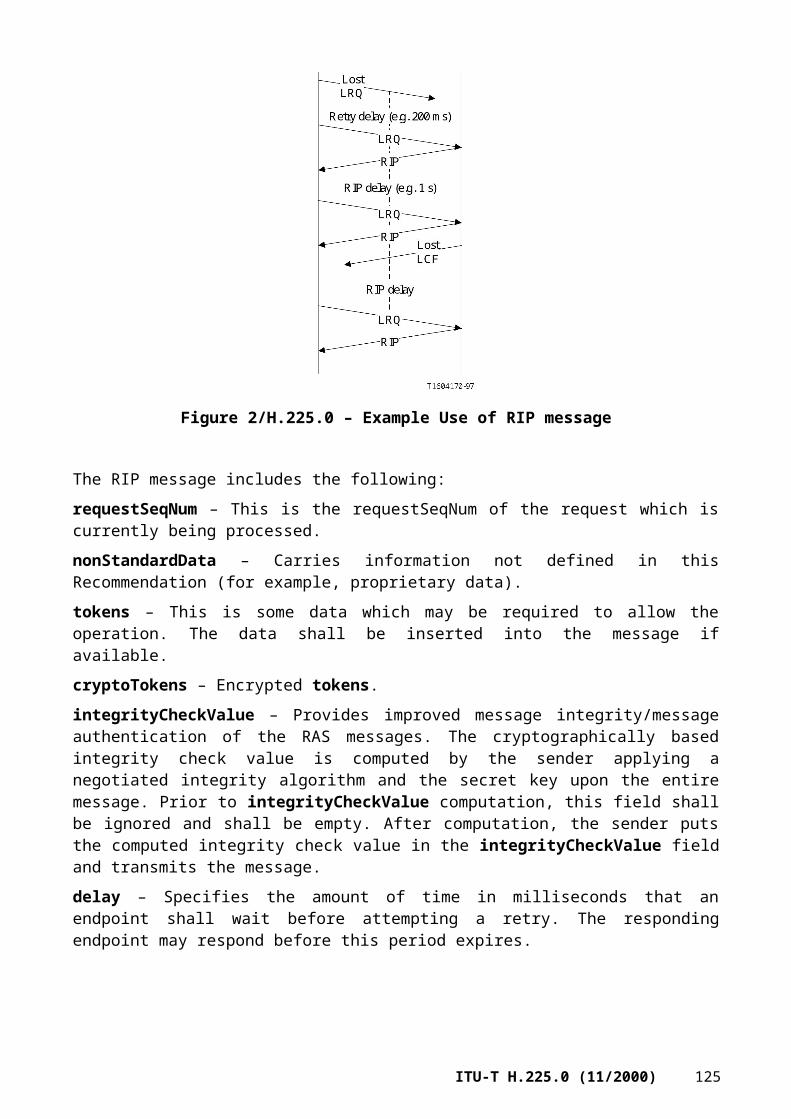
above 5000 to accommodate port number allocation practice within the Unix operating system, where port numbers below 1024 can only be used by privileged processes and port numbers between 1024 and 5000 are automatically assigned by the operating system.
ANNEX C
RTP payload format for H.261 video streams
See the introduction to Annex A; all the warnings mentioned there apply to this annex as well. An informative reference to the full IETF document can be found in Appendix III; however, this annex contains all information needed for the implementation of ITU-T H.323.
C.1 Introduction
ITU-T H.261 [12] specifies the encodings used by ITU-T compliant video-conference codecs. Although these encodings were originally specified for fixed data rate ISDN circuits, experiments have shown that they can also be used over packet-switched networks such as the Internet.
The purpose of this annex is to specify the RTP payload format for encapsulating H.261 video streams in RTP (see Annex A).
C.2 Structure of the packet stream
C.2.1 Overview of ITU-T H.261
The H.261 coding is organized as a hierarchy of groupings. The video stream is composed of a sequence of images, or frames, which are themselves organized as a set of Groups of Blocks (GOB). Note that H.261 "pictures" are referred as "frames" in this Recommendation. Each GOB holds a set of three lines of 11 Macro Blocks (MB). Each MB carries information on a group of 16 16 pixels: luminance information is specified for 4 blocks of 8 8 pixels, while chrominance information is given by two "red" and "blue" colour difference components at a resolution of only 8 8 pixels. These components and the codes representing their sampled values are as defined in ITU-R BT.601-5 [C-3].
This grouping is used to specify information at each level of the hierarchy: – At the frame level, one specifies information such as the delay from the previous frame, the
image format, and various indicators. – At the GOB level, one specifies the GOB number and the default quantifier that will be used
for the MBs. – At the MB level, one specifies which blocks are present and which did not change, and
optionally a quantifier and motion vectors.
Blocks which have changed are encoded by computing the Discrete Cosine Transform (DCT) of their coefficients, which are then quantized and Huffman encoded (Variable Length Codes).
The H.261 Huffman encoding includes a special "GOB start" pattern, composed of 15 zeros followed by a single 1, that cannot be imitated by any other code words. This pattern is included at the beginning of each GOB header (and also at the beginning of each frame header) to mark the separation between two GOBs, and is in fact used as an indicator that the current GOB is terminated. The encoding also includes a stuffing pattern, composed of seven zeros followed by four ones; that stuffing pattern can only be entered between the encoding of MBs, or just before the GOB separator.
128 ITU-T H.225.0 (11/2000)

C.2.2 Considerations for packetization
H.261 codecs designed for operation over ISDN circuits produce a bit stream composed of several levels of encoding specified by ITU-T H.261 and companion Recommendations. The bits resulting from the Huffman encoding are arranged in 512-bit frames, containing 2 bits of synchronization, 492 bits of data and 18 bits of error-correcting code. The 512-bit frames are then interlaced with an audio stream and transmitted over p 64 kbit/s circuits according to ITU-T H.221 [C-1].
When transmitting over the Internet, we will directly consider the output of the Huffman encoding. All the bits produced by the Huffman encoding stage will be included in the packet. We will not carry the 512-bit frames, as protection against bit errors can be obtained by other means. Similarly, we will not attempt to multiplex audio and video signals in the same packets, as UDP and RTP provide a much more efficient way to achieve multiplexing.
Directly transmitting the result of the Huffman encoding over an unreliable stream of UDP datagrams would, however, have poor error resistance characteristics. The result of the hierarchical structure of H.261 bit stream is that one needs to receive the information present in the frame header to decode the GOBs, as well as the information present in the GOB header to decode the MBs. Without precautions, this would mean that one has to receive all the packets that carry an image in order to properly decode its components.
If each image could be carried in a single packet, this requirement would not create a problem. However, a video image or even one GOB by itself can sometimes be too large to fit in a single packet. Therefore, the MB is taken as the unit of fragmentation. Packets must start and end on a MB boundary, i.e. a MB cannot be split across multiple packets. Multiple MBs may be carried in a single packet when they will fit within the maximal packet size allowed. This practice is recommended to reduce the packet send rate and packet overhead.
To allow each packet to be processed independently for efficient resynchronization in the presence of packet losses, some state information from the frame header and GOB header is carried with each packet to allow the MBs in that packet to be decoded. This state information includes the GOB number in effect at the start of the packet, the macroblock address predictor (i.e. the last MBA encoded in the previous packet), the quantizer value in effect prior to the start of this packet (GQUANT, MQUANT or zero in case of a beginning of GOB) and the reference Motion Vector Data (MVD) for computing the true MVDs contained within this packet. The bit stream cannot be fragmented between a GOB header and MB 1 of that GOB.
Moreover, since the compressed MB may not fill an integer number of octets, the data header contains two 3-bit integers, SBIT and EBIT, to indicate the number of unused bits in the first and last octets of the H.261 data, respectively.
C.3 Specification of the packetization scheme
C.3.1 Usage of RTP
The H.261 information is carried as payload data within the RTP protocol. The following fields of the RTP header are specified: – The payload type should specify H.261 payload format (see Annex B). – The RTP timestamp encodes the sampling instant of the first video image contained in the
RTP data packet. The RTP timestamp shall be the same on successive packets if a video image of the same video picture occupies more than one packet. For H.261 video streams, the RTP timestamp is based on a 90 kHz clock. This clock rate is a multiple of the natural H.261 frame rate (i.e. 30 000/1001 or approx. 29.97 Hz). That way, for each frame time, the clock is just incremented by the multiple and this removes inaccuracy in calculating the timestamp. Furthermore, the initial value of the timestamp is random (unpredictable) to make known-plaintext attacks on encryption more difficult, see RTP (Annex A). Note that if
ITU-T H.225.0 (11/2000) 129

multiple frames are encoded in a packet (e.g. when there are very little changes between two images), it is necessary to calculate display times for the frames after the first using the timing information in the H.261 frame header. This is required because the RTP timestamp only gives the display time of the first frame in the packet.
– The marker bit of the RTP header is set to one in the last packet of a video frame, and otherwise, must be zero. Thus, it is not necessary to wait for a following packet (which contains the start code that terminates the current frame) to detect that a new frame should be displayed.
The H.261 data will follow the RTP header, as in:
The H.261 header is defined as following:
The fields in the H.261 header have the following meanings:
Start Bit Position (SBIT): 3 bits – Number of bits that should be ignored in the first data octet.
End Bit Position (EBIT): 3 bits – Number of bits that should be ignored in the last data octet.
INTRA-frame encoded data (I): 1 bit – Set to 1 if this stream contains only INTRA-frame coded blocks. Set to 0 if this stream may or may not contain INTRA-frame coded blocks. The sense of this bit may not change during the course of the session.
Motion Vector flag (V): 1 bit – Set to 0 if motion vectors are not used in this stream. Set to 1 if motion vectors may or may not be used in this stream. The sense of this bit may not change during the course of the session.
GOB Number (GOBN): 4 bits – Encodes the GOB number in effect at the start of the packet. Set to 0 if the packet begins with a GOB header.
Macroblock Address Predictor (MBAP): 5 bits – Encodes the macroblock address predictor (i.e. the last MBA encoded in the previous packet). This predictor ranges from 0 to 32 (to predict the valid MBAs 1-33), but because the bit stream cannot be fragmented between a GOB header and MB 1, the predictor at the start of the packet can never be 0. Therefore, the range is 1-32, which is biased by –1 to fit in 5 bits. For example, if MBAP is 0, the value of the MBA predictor is 1. Set to 0 if the packet begins with a GOB header.
130 ITU-T H.225.0 (11/2000)

Quantizer (QUANT): 5 bits – Quantizer value (MQUANT or GQUANT) in effect prior to the start of this packet. Set to 0 if the packet begins with a GOB header.
Horizontal Motion Vector Data (HMVD): 5 bits – Reference horizontal motion vector data (MVD). Set to 0 if V flag is 0 or if the packet begins with a GOB header. HMVD values are 5-bit 2's complement numbers directly representing the values [–16, +15], where –16 is not used.
Vertical motion vector data (VMVD): 5 bits – Reference vertical motion vector data (MVD). Set to 0 if V flag is 0 or if the packet begins with a GOB header. VMVD values are 5-bit 2's complement numbers directly representing the values [–16, +15], where –16 is not used.
Note that the I and V flags are hint flags, i.e. they can be inferred from the bit stream. They are included to allow decoders to make optimizations that would not be possible if these hints were not provided before bit stream was decoded. Therefore, these bits cannot change for the duration of the stream. A conformant implementation can always set V = 1 and I = 0.
Horizontal and vertical motion vector data must be set to zero when the MTYPE of the last MB encoded in the previous packet was not motion compensated.
C.3.2 Recommendations for operation with hardware codecs
Packetizers for hardware codecs can trivially figure out GOB boundaries using the GOB-start pattern included in the H.261 data. (Note that software encoders already know the boundaries.) The cheapest packetization implementation is to packetize at the GOB level all the GOBs that fit in a packet. But when a GOB is too large, the packetizer has to parse it to do MB fragmentation. (Note that only the Huffman encoding must be parsed and that it is not necessary to fully decompress the stream, so this requires relatively little processing; example implementations can be found in Appendix III.) It is recommended that MB level fragmentation be used when feasible in order to obtain more efficient packetization. Using this fragmentation scheme reduces the output packet rate and therefore reduces the overhead.
At the receiver, the data stream can be depacketized and directed to a hardware codec's input. If the hardware decoder operates at a fixed bit rate, synchronization may be maintained by inserting the stuffing pattern between MBs (i.e. between packets) when the packet arrival rate is slower than the bit rate.
C.3.3 Packet loss issues
On the Internet, most packet losses are due to network congestion rather than transmission errors. Using UDP, no mechanism is available at the sender to know if a packet has been successfully received. It is up to the application, i.e. coder and decoder, to handle the packet loss. Each RTP packet includes a sequence number field which can be used to detect packet loss.
ITU-T H.261 uses the temporal redundancy of video to perform compression. This differential coding (or INTER-frame coding) is sensitive to packet loss. After a packet loss, parts of the image may remain corrupt until all corresponding MBs have been encoded in INTRA-frame mode (i.e. encoded independently of past frames). There are several ways to mitigate packet loss: 1) One way is to use only INTRA-frame encoding and MB level conditional replenishment.
That is, only MBs that change (beyond some threshold) are transmitted. 2) Another way is to adjust the INTRA-frame encoding refreshment rate according to the
packet loss observed by the receivers. ITU-T H.261 specifies that a MB is INTRA-frame encoded at least every 132 times it is transmitted. However, the INTRA-frame refreshment rate can be raised in order to speed the recovery when the measured loss rate is significant.
3) The fastest way to repair a corrupted image is to request an INTRA-frame coded image refreshment after a packet loss is detected. One means to accomplish this is for the decoder to send to the coder a list of packets lost. The coder can decide to encode every MB of every GOB of the following video frame in INTRA-frame mode (i.e. Full INTRA-frame encoded),
ITU-T H.225.0 (11/2000) 131

or if the coder can deduce from the packet sequence numbers which MBs were affected by the loss, it can save bandwidth by sending only those MBs in INTRA-frame mode. This mode is particularly efficient in point-to-point connection or when the number of decoders is low. The next clause specifies how the refresh function may be implemented.
C.3.4 Use of optional H.261-specific control packets
This Recommendation defines two H.261-specific RTCP control packets, "Full INTRA-frame Request" and "Negative Acknowledgement", described in the next clause. Their purpose is to speed up refreshment of the video in those situations where their use is feasible. Support of these H.261-specific control packets by the H.261 sender is optional; in particular, early experiments have shown that the usage of this feature could have very negative effects when the number of sites is very large. Thus, these control packets should be used with caution.
The H.261-specific control packets differ from normal RTCP packets in that they are not transmitted to the normal RTCP destination transport address for the RTP session (which is often a multicast address). Instead, these control packets are sent directly via unicast from the decoder to the coder. The destination port for these control packets is the same port that the coder uses as a source port for transmitting RTP (data) packets. Therefore, these packets may be considered "reverse" control packets.
As a consequence, these control packets may only be used when no RTP mixers or translators intervene in the path from the coder to the decoder. If such intermediate systems do intervene, the address of the coder would no longer be present as the network-level source address in packets received by the decoder, and in fact, it might not be possible for the decoder to send packets directly to the coder.
Some reliable multicast protocols use similar NACK control packets transmitted over the normal multicast distribution channel, but they typically use random delays to prevent a NACK implosion problem. The goal of such protocols is to provide reliable multicast packet delivery at the expense of delay, which is appropriate for applications such as a shared whiteboard.
On the other hand, interactive video transmission is more sensitive to delay and does not require full reliability. For video applications it is more effective to send the NACK control packets as soon as possible, i.e. as soon as a loss is detected, without adding any random delays. In this case, multicasting the NACK control packets would generate useless traffic between receivers since only the coder will use them. But this method is only effective when the number of receivers is small, e.g. if the H.261-specific control packets are used only in point-to-point connections or in point-to- multipoint connections when there are less than 10 participants in the conference.
C.3.5 Control packets definition
C.3.5.1 Full INTRA-frame Request (FIR) packet
This packet indicates that a receiver requires a full encoded image in order to either start decoding with an entire image or to refresh its image and speed the recovery after a burst of lost packets. The receiver requests the source to force the next image in full "INTRA-frame" coding mode, i.e. without using differential coding. The various fields are defined in the RTP specification (Annex A). SSRC
132 ITU-T H.225.0 (11/2000)

is the synchronization source identifier for the sender of this packet. The value of the packet type (PT) identifier is the constant RTCP_FIR (192).
C.3.5.2 Negative Acknowledgements (NACK) packet
The format of the NACK packet is as follows:
The various fields T, P, PT, length and SSRC are defined in the RTP specification (see Annex A). The value of the Packet Type (PT) identifier is the constant RTCP_NACK (193). SSRC is the synchronization source identifier for the sender of this packet.
The two remaining fields have the following meanings:
First Sequence Number (FSN): 16 bits – Identifies the first sequence number lost.
Bitmask of following Lost Packets (BLP): 16 bits – A bit is set to 1 if the corresponding packet has been lost, and set to 0 otherwise. BLP is set to 0 only if no packet other than that being NACKed (using the FSN field) has been lost. BLP is set to 0x00001 if the packet corresponding to the FSN and the following packet have been lost, etc.
C.4 Bibliography
[C-1] ITU-T H.221 (1999), Frame structure for a 64 to 1920 kbit/s channel in audiovisual teleservices.
[C-2] ITU-T H.261 (1993), Video codec for audiovisual services at p 64 kbit/s.
[C-3] ITU-R BT.601-5 (1995), Studio encoding parameters of digital television for standard 4:3 and wide-screen 16:9 aspect ratios.
ANNEX D
RTP payload format for H.261A video streams
D.1 Introduction
To facilitate interfacing H.323 video streams to the SCN via gateways, ITU-T H.323 defines a modified form of the RTP H.261 video payload. This eases buffer management and interoperability with remote SCN codecs. Support of the H.261A payload type is signalled using H.245 capability sets and in the openLogicalChannel message using RTP dynamic payload types.
D.2 H.261A RTP packetization
This version is an extension of the version described in Annex C except that an additional 32-bit word is appended to the H.261 header. The procedures that are described in Annex C also apply to this annex.
ITU-T H.225.0 (11/2000) 133

The H.261A data will follow the RTP header, as in:
The H.261A header is defined as:
The fields in the H.261A header have the following meanings:
H.261 header: 32 bits – As described in Annex C.
Last GOB Number (LGOBN): 4 bits – The GOB number of the last GOB in the RTP packet (max GOB number is 12 for ITU-T H.261).
Reserved (RES): Reserved.
Byte Count: 24 bits – Indicates the cumulative number of octets that have been sent in the H.261 stream part of the RTP packets. If the last byte of a packet is only partially filled (as indicated by EBIT), then it is not counted in the cumulative byte count. This modulo 224 byte count starts at a random value and is never reset.
Both of the additional fields may be used when packets are lost or delivered out of order. The Byte Count can be used to determine how much stuffing will be needed in the SCN stream and facilitates buffer management. The last GOB number simplifies determining which GOBs have been lost due to packet loss.
ANNEX E
Video packetization
This annex describes RTP packetization details for video codecs. Table E.1 provides references to the definitions of video packetization formats that are not defined in this Recommendation. The remaining clauses of this annex define additional video packetization formats.
134 ITU-T H.225.0 (11/2000)

Table E.1/H.225.0 – Externally defined video packetization formats
Encoding name Packetization definition
ISO/IEC 14496-2 (MPEG-4 Video)
IETF RFC 3016, RTP Payload Format for MPEG-4 Audio/Visual Streams
E.1 H.263
An RTP payload format for H.263 video is specified in IETF RFC 2190 for H.263 video bitstreams that do not contain the new features adopted in version 2 (the 1998 version) of ITU-T H.263 (the features using PLUSPTYPE or annexes subsequent to Annex H/H.263). An additional payload format which supports the enhanced features of H.263 version 2 bitstreams will be specified at a later date. A legacy packetization format widely used in industry (not as specified in IETF RFC 2190) may only be used if the peer indicated support for this format in the capability exchange.
Clause B.5 describes the procedure to use to signal H.263 video streams.
ANNEX F
Audio and multiplexed packetization
This annex describes RTP packetization details for audio codecs. Table F.1 provides references to the definitions of audio packetization formats that are not defined by this Recommendation. Table F.2 provides references to the definitions of multiplexed packetization formats. The remaining clauses of this annex define additional audio packetization formats.
Table F.1/H.225.0 – Externally defined audio packetization formats
Encoding name Packetization definition
ISO/IEC 14496-3 (MPEG-4 Audio)
IETF RFC 3016, RTP Payload Format for MPEG-4 Audio/Visual Streams
Table F.2/H.225.0 – Externally defined multiplexed stream packetization formats
Encoding name Packetization definition
H.222 multiplexed streams (MPEG-2 transport streams)
IETF RFC 2250, RTP Payload Format for MPEG1/MPEG2 Video
F.1 G.723.1
This Recommendation specifies a coded representation that can be used for compressing the speech signal component of multimedia services at a very low bit rate. A G.723.1 frame can be one of three sizes: 24 bytes (6.3 kbit/s frame), 20 bytes (5.3 kbit/s frame), or 4 bytes. These 4-byte frames are called SID frames (Silence Insertion Descriptor) and are used to specify comfort noise parameters. There is no restriction on how 4-, 20-, and 24-byte frames are intermixed. The least significant two bits of the first octet in the frame determine the frame size and codec type (refer to Table 5/G.723.1 and Table 6/G.723.1 for more information on bit order). It is possible to switch between the two rates at any 30 ms frame boundary. Both (5.3 kbit/s and 6.4 kbit/s) rates are a mandatory part of the encoder and decoder. This coder was optimized to represent speech with near-toll quality at the above rates using a limited amount of complexity.
ITU-T H.225.0 (11/2000) 135
All the bits of the encoded bit stream are transmitted always from the least significant bit towards the most significant bit. Note that this refers to the order of bits presented to the transport layer and not the order of bits on the wire.
G.723.1 packetization conforms to Annex B except for the packetization interval (30 ms vs. 20 ms default):1) The first packet of a talkspurt (first packet after a silence period) is distinguished by setting
the marker bit in the RTP data header.2) The sampling frequency (RTP clock frequency) is 8000 Hz.3) The packetization interval shall have a duration of 30 ms (one frame) as opposed to the
default packetization of 20 ms.4) Codecs should be able to encode and decode several consecutive frames within a single
packet.5) A receiver should accept packets representing between 0 and 180 ms of audio data as
opposed to the default of 0 and 200 ms.
F.2 G.728
1) Frame packetization:A G.728 frame (4 vectors: V1-V4, 10 bits each, V1 is the older – first to be played) is organized into 5 bytes (B1-B5). Referring to the figure below, the principle for bit order is "maintenance of bit significance". Bits from older vectors are more significant than bit from newer vectors. The Most Significant Bit (MSB) of the frame goes to MSB of B1 and the Least Significant Bit (LSB) of the frame goes to LSB of B5. For clarification: more significant bits from each vector are put in more significant bits of B1-B5 (the more significant bits of lower number B).
For example: B1 contains 8 most significant bits of V1, MSB of V1 is MSB of B1. B2 contains 2 least significant bits of V2, the more significant of the two in its MSB, and 6 most significant bits of V2, the most significant of them is more significant at B2 also.B1 shall be put first to the packet (most significant byte in RTP) and B5 last.
2) Multi-frame packetization:Ending a single frame in an RTP packet might cause considerable network overhead. Therefore, sending a multi-frame packet is allowed in the following manner: An RTP G.728 packet shall contain a whole number of frames. Older frames (to be played first) shall be put first into the RTP packet.
136 ITU-T H.225.0 (11/2000)
The timestamp would reflect the capturing time of the first sample, in the first vector (V1) of the first frame (the oldest information in the packet).
3) The marker bit shall retain the same meaning assigned to it in this Recommendation.
F.3 G.729
This Recommendation specifies a coded representation that can be used for compressing the speech signal component of multi-media services at a bit rate of 8 kbit/s. This coder was optimized to represent speech with toll or wireline quality at 8 kbit/s. This coder has an inherent robustness against random bit errors as well as against randomly and bursty erased frames. It represents speech with a high quality when operating in a noisy environment. A complexity-reduced version of the G.729 algorithm is specified in Annex A/G.729. A floating point version of these two algorithms is specified in Annex C/G.729. The speech coding algorithms in the main body of ITU-T G.729, in Annex A/G.729 and in Annex C/G.729 are fully interoperable with each other, so there is no need to further distinguish between them.
A Voice Activity Detector (VAD) and Comfort Noise Generator (CNG) algorithm in Annex B/G.729 is recommended. This algorithm is applied to Annex F/G.729 (6.4 kbit/s with VAD/CNG), Annex G/G.729 (11.8 kbit/s with VAD/CNG), Annex B/G.729 (G.729 and Annex A/G.729 with VAD/CNG) and Annex I/G.729. A G.729 or Annex A/G.729 frame contains 10 octets; an Annex D/G.729 frame contains 8 octets; an Annex E/G.729 frame contains 15 octets; and the Annexes B/G.729, F/G.729 and G/G.729 comfort noise frame occupies 2 octets, as shown in Figure F.1.
Figure F.1/H.225.0 – Annexes B/G.729 F/G.729and G/G.729 CNG packetization format
The transmitted parameters of a G.729, Annex A/G.729 or Annex C/G.729 10-ms frame, consisting of 80 bits, are defined in Table 8/G.729. The mapping of these parameters is given in Figure F.2. Bits are numbered as Internet order, that is, the most significant bit is bit 0.
ITU-T H.225.0 (11/2000) 137
Figure F.2/H.225.0 – G.729, Annex A/G.729 andAnnex C/G.729 packetization format
Annex D/G.729 defines a 6.4 kbit/s rate extension of G.729 for momentary reduction in channel capacity, e.g. to handle overload conditions. Annex E/G.729 provides an 11.8 kbit/s extension of G.729 for better performance with a wide range of input signals, such as speech with background noise and music. Additionally, Annex E/G.729 has two operating modes, backward and forward adaptive, which are signalled by the first two bits in the packet header.
The bits of a G.729-6.4 frame are formatted as shown in Figure F.3 (see Table D.1/G.729). Bits are numbered in Internet order; that is, the most significant bit is bit 0. A total of 64 bits are used.
Figure F.3/H.225.0 – G.729-6.4 packetization format
The net bit rate for the Annex E/G.729 algorithm is 11.8 kbit/s and a total of 118 bits are used. The bits of a G.729-12 frame are formatted as shown in Figures F.4 and F.5 (see Table E.1/G.729). Figures F.4 and F.5 describe the fields for the forward adaptive mode and the backward adaptive mode respectively for the Annex E/G.729 algorithm. The two least significant bits are included as "don't care" bits and are used to complete an integer number of octets for the frame.
138 ITU-T H.225.0 (11/2000)

Figure F.4/H.225.0 – G.729-12 packetization format for the forward adaptive mode
ITU-T H.225.0 (11/2000) 139

Figure F.5/H.225.0 – G.729-12 packetization format for the backward adaptive mode
An RTP packet may consist of zero or more G.729 or Annex A, C, D or E/G.729 frames, followed by zero or one Annex B/G.729 payloads. The presence of a comfort noise frame can be deduced from the length of the RTP payload.1) The first packet of a talkspurt (first packet after a silence period) is distinguished by setting
the marker bit in the RTP header.2) The sampling frequency (RTP clock frequency) is 8000 Hz.3) The default packetization interval should have a duration of 20 ms. While 20 ms is the
strongly recommended value, in some situations it may be desireable to send 10-ms packets. For example, consider a transition from voiced to unvoiced in the first 10 ms of the packet. If a 20-ms packetization interval were mandatory, then the transmitter would need to wait until speech is active again.
4) Codecs should be able to encode and decode several consecutive frames within a single packet.
5) A receiver should accept packets representing between 0 and 200 ms of audio data.
F.4 Silence suppression
ITU-T H.225 states that coders may send silence frames before the stop transmission during a silence period. Since not all audio coders have in-band signalling for silence, a general mechanism at the RTP level should be defined. An example might be sending an empty RTP packet. This is for further study.
140 ITU-T H.225.0 (11/2000)

F.5 GSM codecsGSM speech codecs include: GSM full rate (FR) [F-1], GSM half rate (HR) [F-2] and GSM enhanced full rate (EFR) [F-3]. Each codec produces three different speech traffic frame types, i.e.:• Speech frames – Contains actual speech data;• Idle frames – Indicates no voice activity, all data bits are set to one;• Silence Descriptor (SID) frames – Indicates start of a silence period, data describes
background noise. SID frames are marked inband with a fixed bit pattern.
F.5.1 Frame packetizationWith all three GSM codecs speech traffic frame bits are packed into RTP frame most significant bit (MSB) first. One RTP packet may contain one or more GSM speech traffic frames. All endpoints shall be capable of receiving and identifying an idle frame. An idle GSM speech frame is filled with binary 1s.If an endpoint sets the comfortNoise parameter to TRUE, it shall send SID frames as specified in the comfort noise and discontinuous transmission (DTX) specifications of a particular GSM codec. During a silent period, a new SID frame, with (possibly) updated noise information, is sent periodically, that is every 24th frame. After a silence period, the marker bit shall be set to 1 in RTP header.
Full-rate codec GSM full-rate codec sends a 260 bit (32.5 octets) frame every 20 ms. This information shall be packed into RTP frame with a four-bit prefix (0xD or 1101 binary), called signature. Therefore GSM FR payload within RTP shall consist of 33 octets. SID (Silence Descriptor) frame is marked inband by a SID codeword stored into codec parameters as described in reference [F-4] below. The payload size of a SID frame is 33 octets. The signature of a full rate SID frame shall be same as that of a full rate speech frame (0xD). RTP coded FR speech shall have a bit rate of 13 200 bits/s, not including the packetization overhead.
Half-rate codecGSM half-rate codec sends a 112 bit (14 octets) frame every 20 ms. This information shall be packed into an RTP header without any prefixes/signatures. SID frame is marked inband by a SID codeword stored into codec parameters as described in reference [F-4] below. The payload size of a SID frame is 14 octets. RTP coded speech shall have a bit rate of 5600 bits/s, not including the packetization overhead.
Enhanced Full RateGSM EFR codec sends a 244 bit (30.5 octets) frame every 20 ms. This information shall be packed into an RTP header with a four-bit prefix (0xC or 1100 binary), called "signature". Therefore, GSM EFR payload within RTP shall consist of 31 octets. SID frame is marked inband by a SID codeword stored into codec parameters as described in reference [F-4] below. The payload size of a SID frame is 31 octets. RTP-coded EFR speech shall have a bit rate of 12 400 bits/s, not including the packetization overhead.
F.5.2 Informative references
[F-1] GSM 06.10 (ETS 300 961), Digital cellular telecommunications system; Full rate speech; Transcoding.
[F-2] GSM 06.60 (ETS 300 726), Digital cellular telecommunications system; Enhanced Full Rate (EFR) speech transcoding.
[F-3] GSM 06.20 (ETS 300 969), Digital cellular telecommunications system; Half rate speech; Half rate speech transcoding.
ITU-T H.225.0 (11/2000) 141
[F-4] ETSI, TIPHON 03 001 (TS 101 318), Telecommunications and Internet Protocol Harmonization Over Networks (TIPHON); Using GSM speech codecs within ITU-T Recommendation H.323.
[F-5] GSM 06.31 (ETS 300 963), Digital cellular telecommunications system; Full rate speech; Comfort noise aspect for full rate speech traffic channels.
[F-6] GSM 06.81 (ETS 300 729), Digital cellular telecommunications system; Discontinuous Transmission (DTX) for Enhanced Full Rate (EFR) speech traffic channels.
[F-7] GSM 06.41 (ETS 300 972), Digital cellular telecommunications system; Half rate speech; Discontinuous Transmission (DTX) for half rate speech traffic channels.
[F-8] GSM 06.12 (ETS 300 963), Full rate speech; Comfort noise aspect for full rate speech traffic channels.
[F-9] GSM 06.62 (ETS 300 728), Digital cellular telecommunications system; Comfort noise aspects for Enhanced Full Rate (EFR) speech traffic channels.
[F-10] GSM 06.22 (ETS 300 971), Digital cellular telecommunications system; Half rate speech; Comfort noise aspect for the half Rate speech traffic channels.
[F-11] GSM 08.60 (ETS 300 737), Digital cellular telecommunications system; (Phase 2+) (GSM); In-band control of remote transcoders and rate adaptors for Enhanced Full Rate (EFR) and full rate traffic channels.
F.6 G.722.1
The speech coding algorithm defined in ITU-T G.722.1 encodes wideband audio signals with a 50 Hz to 7 kHz bandwidth into one of two bit rates, 24 kbit/s or 32 kbit/s, using 20 ms frames and a sampling rate clock of 16 kHz. The bit rate can be changed at any 20-ms frame boundary, although rate change notification is not provided inband with the bitstream. When operating at 24 kbit/s, 480 bits (60 octets) are produced per frame, and when operating at 32 kbit/s, 640 bits (80 octets) are produced per frame. Thus, both bit rates allow for octet alignment without the need for padding bits.
The number of bits in a frame is fixed. However, within this fixed frame G.722.1 uses variable length coding (e.g. Huffman coding) to represent most of the encoded parameters. Except for the categorization control bits parameter, all other bit stream parameters are represented by variable length codes, a variable number of bits. Figure F.6 illustrates this point and the order of the transmitted parameter fields. All variable length codes and the categorization control bits are transmitted in order from the leftmost (most significant – MSB) bit to the rightmost (least significant – LSB) bit. The use of Huffman coding means that it is not possible to identify the various coder parameters/fields contained within the bit stream without first completely decoding the entire frame.
Figure F.7 illustrates how the G.722.1 bit stream maps into an octet-aligned RTP payload. The encoder bit stream is split into a sequence of octets (60 or 80 depending on the bit rate), and each octet is in turn mapped into an RTP octet.
An RTP packet shall only contain G.722.1 frames of the same bit rate. The RTP timestamp shall be in units of 1/16 000th of a second.
First bit Last bittransmitted transmitted
amplitudeenvelope
bits
categorizationcontrol
bits
MLTcoefficients
bits
variable number of bits 4 bits variable number of bits
142 ITU-T H.225.0 (11/2000)

Figure F.6/H.225.0 – G.722.1 major bitstream fieldsand their order of transmission
First bittransmitted
Last bittransmitted
sequence of bits (480 or 640) generated by the G.722.1 encoder for transmission
MSB ... LSB MSB ... LSB MSB ... LSB ........................ MSB ... LSBRTP octet 1 RTP octet 2 RTP octet 3 RTP octet
60 or 80
Figure F.7/H.225.0 – G.722.1 encoded bitstream mapping to RTP
F.7 TIA/EIA-136 ACELP
This vocoder is optimized for TIA/EIA-136 TDMA Digital Cellular and PCS systems. It includes voice activity detection (VAD), lost frame substitution and comfort noise generation (CNG) capabilities. The sampling rate is 8000 Hz and the compressed voice frame length is 20 ms. The vocoder produces a 148-bit speech-vector, s0 through s147, for each 20-ms voice frame. s0 is the most significant bit (MSB). Please refer to section 4 of reference [F.7-1] for more details.
F.7.1 TIA/EIA-136 ACELP frame format
A speech indicator flag bit, SP, shall be generated by the vocoder and set to "1" to indicate a speech frame, or "0" to indicate a silence (comfort-noise) frame. This SP flag bit shall be inserted in bit-position 148. Bit position 149 is the BFI_CN (bad frame or comfort noise indicator) and bit position 150 is the CNU flag (comfort noise update). Bit position 151 shall always be set to 0.
The logical combinations of these three flags are described below.
The 152-bit (19-octet) transmit frame is depicted in Figure F.8. Octets are formed starting with the LSB and moving towards the MSB. The LSB is transmitted first.
bit 0 (MSB) 1 … 146 147 148 149 150 bit 151 (LSB)s0 s1 … s146 S147 SP BFI_CN CNU Always 0Speech vector/Comfort noise Flag Flag Flag Padding bit
Figure F.8/H.225.0 – ACELP vocoder voice frame
F.7.2 TIA/EIA-136 ACELP silence suppression mode
In silence mode, the vocoder generates an ambient noise frame representation. This frame is used by the vocoder at the receiving end to regenerate the ambient noise of the transmitting end. The CN (comfort noise) parameters vector consists of only 38 bits, to which the three flag bits and seven padding bits (consisting of all zeros) are appended to form a six-octet frame.
ITU-T H.225.0 (11/2000) 143
The 48-bit (6-octet) CN frame is depicted in Figure F.9 below. Octets are formed starting with the LSB and moving towards the MSB. The LSB is transmitted first.
bit 0 (MSB) 1 … 37 38 39 40 41 41-47 (LSB)Cn0 cn1 … cn37 S147 SP BFI_CN CNU Always 0
Speech vector/Comfort noise Flag Flag Flag Padding bit
Key:
SP Speech indicatorBFI_CN Bad Frame Indicator/Comfort Noise IndicatorCNU Comfort Noise Update
The logical values of these flags and their meanings are defined below:
SP: 1 = speech frame; 0 = non-speech (comfort noise frame)
BFI_CN: If SP = 1
And BFI_CN = 1Then, this is a bad-voice frame Otherwise ( BFI_CN = 0), this is a good voice-frame
If SP = 0And BFI_CN = 1Then this is a bad comfort-noise frameOtherwise ( BFI_CN = 0), this is a good comfort-noise frame
CN:If SP = 0 And BFI_CN = 0And CN = 1 Then, this is an update comfort noise frameOtherwise it is a non-valid CN frame
NOTE – A wireless mobile vocoder shall set the BFI_CN to 0. The receiving base station may set this flag to 1 if it is unable to correct errors introduced by the radio channel.
Figure F.9/H.225.0 – ACELP vocoder silence suppression frame
F.7.3 TIA/EIA-136 ACELP packetization
The packetization of IS-ACELPshall be in conformance with Annex B.1) The packetization duration shall be a whole multiple of 20 ms.2) A packet may consist of one or more frames each.3) Codecs should be able to encode and decode several consecutive frames within a single
packet.4) All the bits of the encoded bit stream are transmitted always from the least significant bit
towards the most significant bit.
144 ITU-T H.225.0 (11/2000)

F.7.4 TIA/EIA-136 ACELP referenced standard
[F.7-1] TIA/EIA-136, part 410, TDMA Cellular/PCS – Radio Interface, Enhanced Full Rate Voice Codec (ACELP). Formerly IS-641.
F.8 TIA/EIA-136 US1
This vocoder is optimized for TIA/EIA-136 TDMA Digital Cellular and PCS systems. Reference [F.8-1] provides a detailed description of the vocoder.
F.8.1 TIA/EIA-136 US1 frame format
The sampling rate is 8000 Hz and the compressed voice frame-length is 20 ms. The vocoder produces 244 ordered bits per voice frame. Three flag bits, BFI, SID and TAF, are added to the speech vector. One padding bit (in bit position 247) is added to form a whole number of octets (31). The last bit is referred to as the least significant bit (LSB). This vocoder also supports DTX (discontinuous transmission) silence mode.
The transmit voice frame structure is shown in Figure F.10.
MSB – bit 0 1 … 243 244 245 246 247 (LSB)
s0 s1 … s243 BFI SID TAF Always 0Speech vector Flag Flag Flag Padding bit
Figure F.10/H.225.0 – US1 vocoder voice frame
F.8.2 TIA/EIA-136 US1 silence mode frames (TX-DTX)
In silence mode, special frames called SID (for silence descriptor) frames are transmitted in a schedule specified in section 1.3 of reference[F.8-1].
A SID frame contains the same number of bits as normal speech frames, but the bit-map is different. See reference [F.8-1] for details. The SID frame contains comfort noise (CN) parameters and a 95-bit SID code-word. The SID code-word is all "0"s. Other unused bits in the 244-bit vector payload are also set to "0". (See Figure F.11.)
MSB – bit 0 1 … 243 244 245 246 247 (LSB)cn0 cn1 … cn243 BFI SID TAF Always 0
Comfort noise vector Flag Flag Flag Padding bit
Figure F.11/H.225.0 – Base station to landline,Comfort noise transmit frame (US1)
The logic of the BFI, SID and TAF flags is similar to the equivalent flags of the TIA/EIA-136 ACELP vocoder, described in F.7.
F.8.3 TIA/EIA-136 US1 packetization
The packetization shall be in conformance with Annex B. 1) The packetization duration shall be a whole multiple of 20 ms.2) A packet may consist of zero, one or more frames each.3) Codecs should be able to encode and decode several consecutive frames within a single
packet.
ITU-T H.225.0 (11/2000) 145

4) All the bits of the encoded bit stream are transmitted always from the least significant bit towards the most significant bit.
F.8.4 TIA/EIA-136 US1 reference standard
[F.8-1] TIA/EIA-136, part 430, TDMA Cellular/PCS – Radio Interface, US1 Full Rate Voice Codec.
F.9 IS-127 EVRC
F.9.1 IS-127 EVRC description
F.9.1.1 General
The TIA/EIA IS-127 Enhanced Variable Rate Codec (EVRC) is optimized for TIA/EIA IS-95 CDMA Digital Cellular and PCS systems. The sampling rate is 8000 samples per second and the voice frame length is 20 ms (that is, 160 samples per frame). EVRC encodes active speech at full rate or half rate and background noise (no speech present) at one eighth rate. It delivers toll quality speech at very low average bit rate. A detailed description of the EVRC codec can be found in the publicly available TIA/EIA IS-127 standard [F.9-1].
F.9.1.2 Compression rates
The EVRC coder compresses its input signal using one of three rates: full-rate (rate 1), half-rate (rate 1/2), and eighth-rate (rate 1/8). Full- and half-rates are used primarily for encoding active speech while the eighth-rate is used for encoding background noise (silence mode). All frames are 20 ms long, regardless of encoding rate.
F.9.1.3 Blanked packets
To allow for in-band signalling or for secondary traffic (see section 1.4.1 of [F.9-1]), voice frames are blanked. The generated voice packet is simply not used and the decoder treats it as an erased packet. See [F.9-1] for details.
F.9.1.4 Half rate
Half-rate encoding is used, instead of the normal full-rate, when a signalling message has to be added to the traffic channel.
F.9.1.5 Null 1/8 rate traffic channel data
A rate one-eighth packet in which all bits are set to "1" is considered null Traffic Channel data. Such packets are declared "erased packets" and are handled as described in section 5 of [F.9-1].
Rate information and channel coding bits are added to the vocoder output bits for transport over the air, in accordance with TIA/EIA IS-95.
The packet types, number of bits-per-packet, raw vocoder bit-rates and the aggregate rates (vocoder bits plus additional bits) are shown in Table F.3 below.
146 ITU-T H.225.0 (11/2000)

Table F.3/H.225.0 – EVRC packets and bit rates
Packet Type(3 bits) Rate Bits/Packet Vocoder bit
rateAggregate
rate
1 Full 171 8.55 9.62 Half 80 4.0 4.8
3 (Note) Fourth (service option-1 compatibility)
40
4 Eighth 16 0.8 1.25 Blanked 0 – –6 Full-rate with errors 171 – –7 Bad frame (erasure) 0 – –
NOTE – Type 3 packets may only be generated by older IS-96 encoders. The IS-127 decoder shall treat these packets as erased-packets.
F.9.2 IS-127 EVRC packetization
F.9.2.1 General requirements
The transmission packetization shall be in conformance with Annex B.1) The packetization duration shall be a whole multiple of 20 ms. 2) A transmission packet may consist of zero, one, or more frames. 3) Codecs should be able to encode and decode several consecutive frames within a single
transmission packet. 4) All the bits of the encoded bit stream shall always be transmitted from the least significant
bit towards the most significant bit.
F.9.2.2 Frame formats
F.9.2.2.1 Full rate – F1
The EVRC full-rate, 176-bit (22-octet) transmit frame (F1), is depicted in Figure F.12. Octets are formed starting with the LSB and moving towards the MSB. The LSB (bit 175) is transmitted first.
Bit 0 (MSB) Bits 1 through 170 Bits 171 through 175 (LSB)s0 s1 … s170 Always 0
Speech vector Padding bits
Figure F.12/H.225.0 – F1, Full-rate EVRC frame
F.9.2.2.2 Half rate – F2
The EVRC half-rate, 80-bit (10-octet) transmit frame (F2) is depicted in Figure F.13. Octets are formed starting with the LSB and moving towards the MSB. The LSB (bit 79) is transmitted first.
Bit 0 (MSB) Bits 1 through 79 (LSB)s0 s1 … s79
Speech vector
ITU-T H.225.0 (11/2000) 147
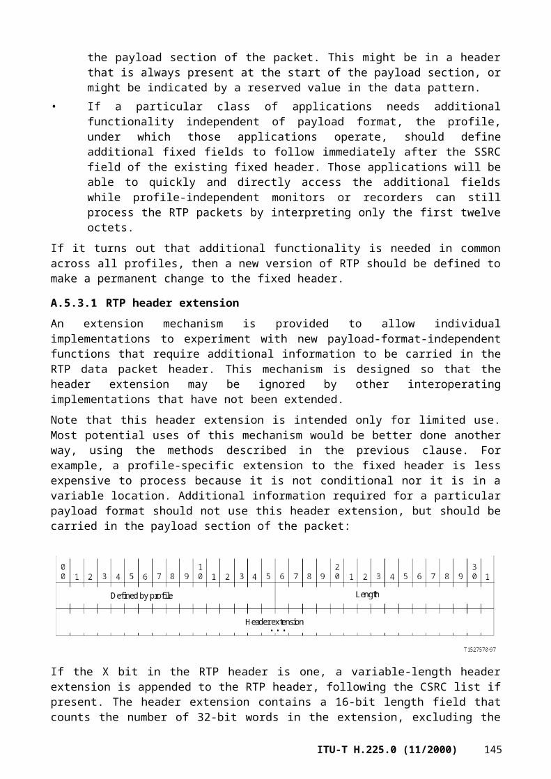
Figure F.13/H.225.0 – F2, Half-rate EVRC frame
F.9.2.2.3 Eighth Rate – F3
The EVRC eighth-rate, 16-bit (2-octets) transmit frame (F3) is depicted in Figure F.14 below. Octets are formed starting with the LSB and moving towards the MSB. The LSB (bit 15) is transmitted first.
Bit 0 (MSB) Bits 1 through 15 (LSB)s0 s1 … s15
Speech vector
Figure F.14/H.225.0 – F3, Eighth-rate EVRC frame
F.9.3 IS-127 EVRC reference standards
[F.9-1] TIA/EIA IS-127 (1997), Enhanced Variable Rate Codec, Speech Service Option 3 for Wideband Spread Spectrum Digital Systems.
[F.9-2] TIA/EIA IS-95-B (1999), Mobile Station-Base Station Compatibility Standard for Wideband Spread Spectrum Cellular Systems.
F.10 H.223 MUX-PDU packetization
F.10.1 Introduction
The H.223 MUX-PDU is used by a packet-oriented multiplexing protocol designed for the exchange of one or more information streams between higher-layer entities such as data and control protocols and audio and video codecs, as defined in ITU-T H.223.
Each information stream is represented by an H.245 unidirectional logical channel which is identified by a unique Logical Channel Number (LCN), an integer between 0 and 65535. LCN 0 is a permanent logical channel assigned to the H.245 control channel. All other logical channels are dynamically opened and closed by the transmitter using the H.245 OpenLogicalChannel and CloseLogicalChannel messages. All necessary attributes of the logical channel are specified in the OpenLogicalChannel message. For applications that require a reverse channel, a procedure for opening bidirectional logical channels is also defined in ITU-T H.245.
The general structure of the multiplexer is shown in Figure 2/H.223. The multiplexer consists of two distinct layers: a Multiplex (MUX) layer and an Adaptation Layer (AL).
Support of the H.223 payload type is signalled using H.245 capability sets and in the H.245 openLogicalChannel message using RTP dynamic payload types.
F.10.2 MUX-PDU packetization format
The H.223 MUX-PDU specified by Figure 3/H.223 is carried as payload data within the RTP protocol. The order of bit transmission is specified in 3.2.2/H.223, and the field mapping convention is in 3.2.3/H.223.
Though a MUX-PDU can occupy more than one RTP packet, a MUX-PDU shall start with the first octet of an RTP packet payload.
Each RTP packet contains a timestamp that is derived from the sender's clock reference. The timestamp shall represent the target transmission time of the first byte of the H.223 MUX-PDU. The
148 ITU-T H.225.0 (11/2000)

primary purpose of this timestamp is for the receiver to estimate and reduce any network-induced jitter, and to reproduce the H.223 bitstream with constant bit rate.
The usage of the fields of the RTP header shall be as follows:1) An RTP dynamic payload type is used.2) The RTP timestamp represents the target transmission time for the first byte of the MUX-
PDU in the packet over the H.223 constant bitrate channel. This timestamp is derived from the clock frequency with a default value of 90 kHz. The sender can change this frequency, and the selected value is signalled by the BitRate parameter in the H223Capability structure in H.245 messages. If a MUX-PDU occupies more than one RTP packet, the RTP timestamp shall be the same on successive packets. The timestamp should be calculated based on the number of bytes included in the transmitted MUX-PDUs.
3) The marker bit of the RTP header is set to one in the last packet of a MUX-PDU, and otherwise must be zero. Thus, it is not necessary to wait for a following packet to detect the MUX-PDU boundary.
The H.223 MUX-PDU follows the RTP header, as in:
RTP header MUX-PDU data
ANNEX G
Communication between administrative domains
G.1 Scope
It is expected that the overall H.323 network will consist of smaller subsets of equipment organized in a manner such as by administrative domains. Because of the potentially large numbers of H.323 equipment that will exist in H.323 networks, an efficient protocol is needed to allow calls to be completed between administrative domains. The most elementary example is for a user (an endpoint) in one administrative domain to reach a user (an endpoint) serviced by another administrative domain. While the H.225.0 RAS protocol can provide many of the needs of communication between administrative domains, it is neither complete nor efficient for this purpose.
This annex describes methods to allow address resolution, access authorization and usage reporting between administrative domains in H.323 systems for the purpose of completing calls between the administrative domains. An administrative domain exposes itself to other administrative domains through a type of logical element known as a border element. A border element may be colocated with any other entity (for example, with a gatekeeper). Annex G does not require an administrative domain to reveal details about its organization or architecture. Annex G does not mandate a specific system architecture within an administrative domain. Furthermore, Annex G supports the use of any call model (gatekeeper routed versus direct endpoint).
The general procedure is for border elements to exchange information regarding the addresses each administrative domain can resolve. Addresses can be specified in a general manner or in an increasingly specific manner. Additional information allows elements within an administrative domain to determine the most appropriate administrative domain to serve as the destination for the call. Border elements may control access to their exposed addresses, and require reports on the usage made during calls to those addresses.
Figure G.1 indicates a number of reference points representing signalling among various elements in an H.323 network. In this figure, the administrative domains are part of a global packet network without edges. Note that this figure is not an explicit definition of an H.323 system architecture, but is meant to illustrate signalling reference points.
ITU-T H.225.0 (11/2000) 149

Figure G.1/H.225.0 – System reference points
The figure indicates the following reference points:A – between border elements;B – between border element and gatekeepers;C – between gatekeepers;D – between H.323 elements and back-end services (not in the scope of this annex).
Reference point A is the focus of this annex. Use of the protocol described in this annex for communication between gatekeepers within an administrative domain is for further study. Reference point B is considered for further study since it is currently assumed that the border element will be colocated with some other H.323 element.
Clause G.9, Signalling examples, provides some signalling examples which may aid understanding.
G.2 Definitions
This annex defines the following terms:
G.2.1 administrative domain: An administrative domain is a collection of H.323 entities administered by one administrative entity. An administrative domain can consist of one or more gatekeepers (that is, one or more zones).
G.2.2 back-end services: Back-end services are functions such as user authentication or authorization, accounting, billing, rating/tariffing, etc. Back-end services and the protocol to exchange information with back-end services (if different than that in this annex) are not in the scope of this annex.
G.2.3 border element: The border element is a functional element which supports public access into an administrative domain for the purposes of call completion or any other services that involve multimedia communication with other elements within the administrative domain. The border element controls the external view of the administrative domain. A border element communicates with other border elements using the protocol specified in this annex. In addition, a border element
150 ITU-T H.225.0 (11/2000)

may, depending on implementation, communicate with other entities within its administrative domain. This element may exist in combination with other H.323 elements, for example a combination of border element, gatekeeper, and gateway. An administrative domain may contain any number of border elements.
G.2.4 clearing house: A service (possibly in the form of a border element) which can provide resolution for all addresses (i.e. a type of aggregation point).
G.3 Abbreviations
This annex uses the following abbreviations:
AD Administrative Domain
BE Border Element
CH Clearing House
DST Daylight Saving Time
EP Endpoint
GK Gatekeeper
GW Gateway
T Terminal
G.4 References
[G-1] ITU-T H.235 (2000), Security and encryption for H-series (H.323 and other H.245-based multimedia terminals).
[G-2] ITU-T H.323 (2000), Packet based multimedia communications systems.
[G-3] ITU-T X.680 (1997) | ISO/IEC 8824-1:1998, Information technology – Abstract Syntax Notation One (ASN.1): Specification of basic notation.
[G-4] ITU-T X.680 (1997)/Amd.1 (1999) | ISO/IEC 8824-1:1998/Amd.1:1999, Information technology – Abstract Syntax Notation One (ASN.1): Specification of basic notation – Amendment 1: Relative object identifiers.
[G-5] ITU-T X.691 (1997) | ISO/IEC 8825-2:1998, Information technology – ASN.1 encoding rules: Specification of Packed Encoding Rules (PER).
G.5 System models
This annex does not mandate a specific system architecture among administrative domains or within an administrative domain. The following subclauses will provide some sample architectures, but these are to be viewed as illustrative rather than exhaustive.
In general, an administrative domain is viewed as consisting of any number of zones and any number of border elements. Remember that a border element is a functional element that may exist together with any other H.323 element. Figure G.2 shows some examples of border element implementations in combination with other elements.
ITU-T H.225.0 (11/2000) 151
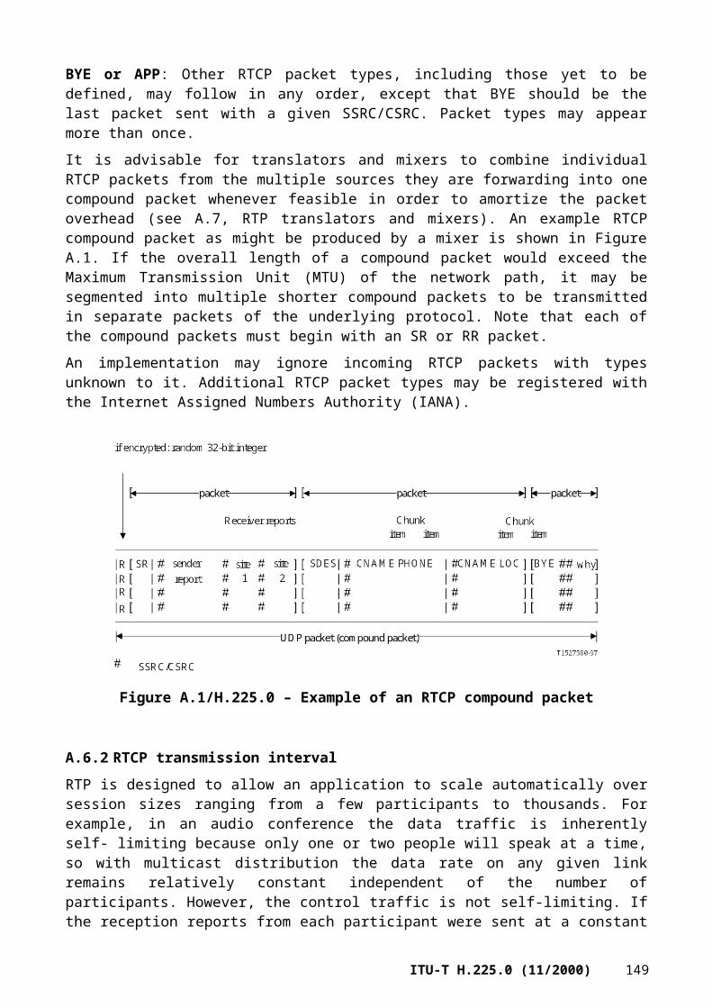
Figure G.2/H.225.0 – Border element placement examples
The relationship among administrative domains may be any of a variety of organizations. The following subclauses indicate example relationships.
G.5.1 Hierarchical
Figure G.3 shows a simple hierarchical arrangement among administrative domains. In such an arrangement, a border element in an administrative domain would consult a border element in an administrative domain higher in the hierarchy to resolve an address.
Figure G.3/H.225.0 – Sample hierarchical organization
152 ITU-T H.225.0 (11/2000)
G.5.2 Distributed or full mesh
An entirely distributed or full mesh model is possible, as shown in Figure G.4. In this example, a border element in each administrative domain communicates with border elements in the other known administrative domains.
Figure G.4/H.225.0 – Sample distributed organization
G.5.3 Clearing house
An example of a clearing house arrangement is shown in Figure G.5. In this arrangement, each administrative domain consults the clearing house to resolve addresses.
Figure G.5/H.225.0 – Sample clearing house organization
G.5.4 Aggregation point
Figure G.6 shows an example of an aggregation point. In this example, administrative domain B is an aggregation point that can provide address resolution for both itself and administrative domains C and D. As an example, administrative domain B may forward resolution requests from administrative domain A to administrative domain C, or may instruct administrative domain A to contact administrative domain C directly for certain destinations. If administrative domain B forwards a request from administrative domain A to administrative domain C, administrative domain B may cache administrative domain C's response.
ITU-T H.225.0 (11/2000) 153
Figure G.6/H.225.0 – Aggregation point example
G.5.5 Overlapping administrative domains
More than one administrative domain may be able to resolve a given address. For example, multiple administrative domains could contain gateways that can complete a call to a terminal in the GSTN. The selection of the appropriate destination administrative domain is the responsibility of the origination administrative domain. The algorithm employed to select the destination administrative domain is an implementation matter.
G.6 Addressing conventions
In order to provide interoperability between domains, it is important that the addressing formats sent in H.323 messages are understood by the receiving system. A border element shall support both the email-id and partyNumber (using PublicNumber with PublicTypeOfNumber of internationalNumber) types of AliasAddress. Note that this requirement implies support of H.225.0 (1998) or later. When communicating with other border elements, only the email-id and partyNumber types of AliasAddress should be used in the destinationAddress field of an LRQ or Setup message unless there has been prior agreement between the administrative domains concerned. For example, if a group of administrative domains have agreed on the interpretation of private local numbers, then these numbers may be used in messages between them.
G.7 Operation
G.7.1 Address templates and descriptors
An address template ("template" for short) defines a set of AliasAddress identifiers, pricing information to complete calls to those addresses, and the protocol to be used in reaching addresses in that set. An administrative domain advertises templates to indicate the calls it can resolve. Templates are grouped together by an identifier known as a "descriptor". Once a template is grouped by a descriptor, any change to a template under that descriptor implies a change to the descriptor "group". Template information may allow the aggregation of addressing information if the addressing scheme is arranged in some hierarchical or routable manner (for example, a given zone might handle 1303538*, meaning all telephone numbers that begin with 1303538). (Note that since "*" is a meaningful character, the template actually includes a Boolean flag to indicate whether the address is specific or not. These examples use "*" to indicate a wildcard, but the actual representation in the template is through the Boolean flag.)
154 ITU-T H.225.0 (11/2000)

Template examples include:
"For 1 555 123 4567 send AccessRequest message to border element A".
"For 1 555 987* send AccessRequest message to border element B".
"For 1 555 987 6543 send Setup message to gateway X".
"For*@example.org send AccessRequest message to border element A".
"For 1* send AccessRequest message to border element B".
"For private 31* send AccessRequest message to border element C".
"For 44 171 112*" doesn't exist".
A border element obtains templates in these ways:• static configuration;• receiving descriptors from other border elements in response to general requests;• receiving responses to specific queries.
G.7.1.1 Static configuration
A border element will maintain templates for all the zones for which it is responsible. These templates may be explicitly provisioned in the border element, or these templates may be formed by summarizing information obtained from gatekeepers within its domain. The border element may make this information available to other border elements via responses to requests. An administrative domain may choose the level of detail to be provided by its border elements. Examples include:• A border element that wishes to hide internal structure might provide one descriptor (with an
indication to send an AccessRequest message) which describes its whole zone and refers to a gatekeeper which will handle all incoming calls.
• A border element which does not care about revealing internal structure might provide a set of templates, each describing the gatekeeper for a zone within the domain.
• A border element which is on a firewall (or one using the gatekeeper-routed model) might provide a template for the whole zone with an indication to send a Setup message.
• A border element with holes in its domain (because numbers have been moved to another administrative domain) provides templates marked "Send AccessRequest" which indicate the border element which should be used to contact the other administrative domain.
• A clearing house border element (such as one which has a complete copy of 44) might hold a template marked "Send Access Request" for each administrative domain within 44.
Border elements need not keep a copy of the whole database. If a border element does not hold a copy of the whole database, then it should contain statically configured "Send AccessRequest" templates indicating a clearing house border element which will be used to resolve other queries.
G.7.1.2 Receiving descriptors
A border element may request the statically configured templates from another border element. The response to the request is decided by the border element from which the templates are being requested.
To request a transfer, the border element sends a DescriptorRequest message specifying the descriptors it wishes to receive. If the owning border element is able to transfer the descriptors, it responds with a DescriptorConfirmation message specifying all the templates.
ITU-T H.225.0 (11/2000) 155

The requesting border element may cache a copy of a template received in this manner until the template's lifetime expires, at which point the border element should delete its copy of the template. If the owning border element changes its statically configured templates before their lifetime has expired, then it shall send a DescriptorUpdate message to those border elements of which it is aware. A border element in receipt of a DescriptorUpdate message should delete, add, or change all indicated templates in its cache, or should request copies of the indicated descriptors from the owner.
An intermediate border element (a border element between the originating and destination administrative domains, such as a clearing house or aggregation point) may publish its own descriptors based on the descriptors it receives. For example, a clearing house may indicate itself as the contact for an AccessRequest message even though the descriptors it received from another border element indicate that other border element as the contact.
A border element may indicate in a template the requirement for an originator to receive permission to place a call into an administrative domain. When the callSpecific flag is set in a template and the message type indicates that an AccessRequest message shall be sent, the originator shall provide per-call information in the AccessRequest message. If a border element receives the AccessRequest message without per-call information and policy is to require per-call information, the border element shall reply with an AccessRejection message with a reason of needCallInformation.
A border element may send a DescriptorUpdate message to other known border elements, or the border element may multicast a DescriptorUpdate message. If a DescriptorUpdate message is multicast, the border element should consider the scope of the multicast. The DescriptorUpdate message can contain the descriptors that have changed. Alternatively, the DescriptorUpdate message may indicate only the identification of the descriptors that changed, allowing the recipient to query for the new information. If a large number of descriptors have changed, the information should be sent in multiple DescriptorUpdate messages so that a particular DescriptorUpdate message does not exceed the maximum transport packet size.
G.7.1.3 Receiving responses to specific queries
A border element may send an AccessRequest message to another border element asking for the resolution of a fully qualified or partially qualified address. The AccessRequest is usually sent over unreliable transport (e.g. UDP), although it may be sent over reliable transport (e.g. TCP).
A border element in receipt of an AccessRequest searches its database and responds with the most specific template for the destination. If multiple templates satisfy the request then the border element shall return all matching templates. If the destination border element is actually responsible for the alias address specified, the border element will usually respond with a template indicating that either an AccessRequest or Setup message should be sent. If the destination border element is a clearing house, it will normally respond with a template indicating that the AccessRequest message should be sent.
The destination border element may also add templates to the response which it believes will be useful in the future. The addition of these templates should not make the response so large that the transport network will need to fragment it (e.g. 576 octets for IPv4 or 1200 octets for IPv6).
For example, a border element which is tightly coupled with a fire wall may provide two templates in its response to AccessRequest messages: one template with a short lifetime (of a few minutes or seconds) specifying the location to which a Setup message should be sent, and additional templates specifying that AccessRequest messages should be sent to the border element for other AliasAddresses within the administrative domain.
A border element may cache a template received in an AccessConfirmation until its lifetime expires.
156 ITU-T H.225.0 (11/2000)
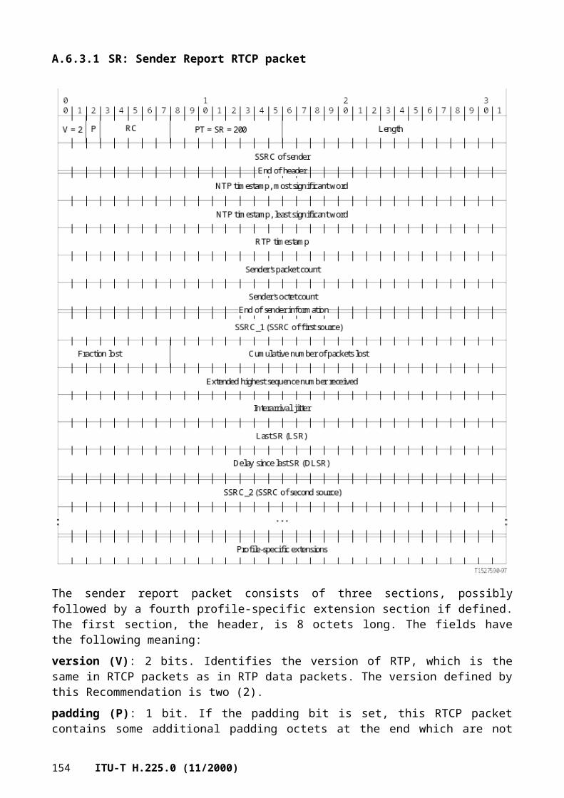
G.7.2 Discovery of a border element or a set of border elements
G.7.2.1 Static
A border element may have an administered set of other border elements which it may contact for address resolution. This administered set may be defined through a set of bilateral agreements between the administrative domains and other administrative domains. The administrative domains may optionally utilize the service of a clearing house.
G.7.2.2 Dynamic
On IP networks, ownership of email-ID style addresses is defined by the DNS system. Thus, in the absence of any better information, a border element may do a DNS SRV record lookup on the part of the email-ID to the right of the "@" sign (for example, a DNS SRV lookup on _h2250-annex-g._udp.example.org for [email protected]). The response to this lookup should be used to synthesize a "Send AccessRequest" template which can be used during the resolution process. Templates synthesized from DNS requests should not be cached for longer than the lifetime provided in the DNS response.
G.7.2.3 Other methods
The use of other methods to locate another border element are for further study.
G.7.3 Resolution procedures
G.7.3.1 Resolution procedure within an administrative domain
When a border element is asked to resolve an AliasAddress (e.g. by a colocated gateway or gatekeeper), it finds matching templates in its cache.
If more than one template matches, appropriate templates are selected and sorted according to local policy. For example, templates may be first sorted by wildcard length (more specific templates are better), then sorted by the type of protocol specified ("Send Setup" is better than "Send AccessRequest").
If multiple templates satisfy the request, then the border element shall return all matching templates.
If the template selection procedure produces no templates marked as "Send Setup", then the border element sends an AccessRequest message with a specific destination address to the address specified in the template. When it gets an answer from the border element, it may store that in its cache and return to the requester the address to which to send the Setup message.
G.7.3.2 Resolution procedure between administrative domains
When a border element receives an AccessRequest, it searches through the templates in its cache and finds those which match the address in the query.
If more than one template matches, they are first sorted by wildcard length (more specific templates are better). They are then sorted by the message type specified ("Send Setup" is better than "Send AccessRequest"). In each case all templates other than the most specific match are discarded.
If the matched templates are marked as "Send AccessRequest" then the border element may choose to forward the AccessRequest message to the border element(s) specified in the template(s), or may choose to return the templates as they are. If the hop counter in the received AccessRequest message has reached zero, then the border element cannot forward the AccessRequest message to another border element, but should instead return any matching templates. If the hop counter has reached zero and the border element has no information to provide in an AccessConfirmation, the border element should respond with an AccessRejection message indicating that the hop count was exceeded.
ITU-T H.225.0 (11/2000) 157

At this point, the border element may use a border element of a third administrative domain (e.g. a clearing house) to authorize the access request. To do that, it sends a ValidationRequest message, carrying access tokens supplied by the requesting border element in the AccessRequest rights. The recipient border element validates the tokens and returns ValidationConfirmation.
The border element then returns an AccessConfirmation message containing the templates which it has found (these will have the same address and message type fields) and any other templates which it considers will be useful.
If multiple templates satisfy the request, then the border element shall return all matching templates.
If the access request contains specific call information, then the returned templates are valid only for the call requested. This is used when an administrative domain wishes to grant access on a per-call basis. In that case, the administrative domain may mandate the inclusion of call information per each AccessRequest sent to it. It does so by setting a flag in the templates that refer to it.
G.7.4 Usage information exchange
Administrative domains may request other domains to provide them information about the usage of resources in specific calls. UsageIndication messages may be provided at any stage of the call. Also, multiple usage indications may be sent for the same call, each one with more up-to-date information.
Usage Indications may be exchanged only if the two border elements have service relationship between them.
UsageIndication requests shall be sent when a border element requires that, either in the templates for which it serves as contact, or by indicating that in either one of the UsageRequest, AccessRequest, ValidationRequest and ValidationConfirmation messages sent in the context of the call for which UsageIndication is required.
G.8 Protocol
Messages in the protocol of this annex may be sent over an unreliable transport service (e.g. UDP) or a reliable transport service (e.g. TCP) to a well-known address. On IP networks, the well-known port 2099 should be used for both TCP and UDP, unless another port has been communicated to the sender. Border elements shall listen on both TCP and UDP ports.
When messages are sent over the reliable transport service, multiple messages may be sent within the boundaries defined by the reliable transport protocol data unit (PDU) as long as whole messages are sent. (In IP implementations, as outlined in Appendix IV, this PDU is defined by TPKT.)
When using unreliable transport service, request messages may be retransmitted. The default value of the retransmission timer should determined by an adaptive delay sensitive method (such as the one used by the TCP protocol). Exponential backoff shall be used for subsequent retransmissions. The number of retransmissions shall not exceed 5. Responses shall not be retransmitted.
In UDP IP implementations, messages shall also be prefixed with TPKT headers, to enable multiple messages per packet. The UDP packet length field shall hold the total length of the payload, including all the messages and their TPKT headers.
G.8.1 Security considerations
When authentication, integrity, and encryption is desired for messages exchanged between border elements, the operation of IP security shall be followed as described in IETF RFC 1825 ("Security Architecture for the Internet Protocol"), including either, or both, of IETF RFC 1826 ("IP Authentication Header"), and IETF RFC 1827 ("IP Encapsulating Security Payload (ESP)").
158 ITU-T H.225.0 (11/2000)
Where appropriate, the procedures and constructs of ITU-T H.235 shall be utilized to support application-level security. Specifically, the token formats and authentication exchanges shall be used. Tokens and crypto-tokens received in response messages should be used in a subsequent related request.
G.8.2 Message definitions
Each message contains a set of common fields in addition to the message-specific information. The common fields are:
Field Description
sequenceNumber Each request or update message contains a unique sequence number. The message sent in response to a request message (a confirmation or rejection message) uses the sequence number from the request message. Retransmitted messages shall have the same sequence number.
replyAddress This is the address to which to send the reply to a request message. Any request message shall include a replyAddress, unless the request was sent over a bidirectional connection-oriented transport (e.g. TCP). Any message other than a request message shall not include a replyAddress.
version Protocol version in use by the sender of this message.
hopCount This defines the number of border elements through which this message may propagate. When a border element receives this message and decides that the message should be forwarded on to another border element, it first decrements hopCount. If hopCount is then greater than 0, the border element inserts the new hop count value into the message to be forwarded. If hopCount has reached 0, the border element shall not forward the message. If the message is a request, the border element should respond with a confirmation message with any applicable information. If no information is available, the border element should respond with a rejection message.
integrityCheckValue Provides improved message integrity/message authentication. The cryptographically based integrity check value is computed by the sender applying a negotiated integrity algorithm and the secret key upon the entire message. Prior to integrityCheckValue computation, each byte of this field shall be set to zero. After computation, the sender puts the computed integrity check value in the integrityCheckValue field and transmits the message.
tokens This is some data which may be required to allow the operation. The data shall be inserted into the message if available.
cryptoTokens Encrypted tokens.
nonStandard Non-standard information.
ITU-T H.225.0 (11/2000) 159

G.8.2.1 Descriptor
The Descriptor is not a message, but is rather a message element used to label a set of templates.
The Descriptor contains the following information:
Field Description
descriptorInfo This holds a unique identifier for the descriptor and the time it was last changed (see Descriptor information below).
templates This is a set of templates which define the addresses this descriptor can resolve.
gatekeeperID This is a text identifier that indicates the owner of the descriptor (i.e. the gatekeeper that created this message).
G.8.2.2 Descriptor information
Descriptor information uniquely identifies the descriptor and indicates the last time the descriptor changed.
Field Description
descriptorID This is a globally unique identifier used to identify this descriptor from among many possible descriptors.
lastChanged This is the date and time this descriptor was last changed.
G.8.2.3 Address Template
The Address Template describes a set of one or more alias addresses. The Template is not a message, but is an element used as a building block for other elements. The Template consists of other structures, which are described in the following subclauses.
Field Description
pattern This is a list of patterns (see Pattern below).
routeInfo This is a list of route information for this template (see Route Information below).
timeToLive This indicates the time, expressed in seconds, for which this template is valid.
160 ITU-T H.225.0 (11/2000)

G.8.2.3.1 Route Information
The route information structure found in the template (the routeInfo field) contains the following:
Field Description
messageType This indicates the type of message to send when attempting to resolve a specific address within this template. Possibilities are sendAccessRequest, sendSetup, or nonExistent (indicates that the address does not exist).
callSpecific If set to TRUE, authorization is requested for each call to this route, implying that the AccessRequest message shall include the call information. This boolean field has meaning only when messageType is sendAccessRequest; otherwise, callSpecific shall be set to FALSE.
usageSpec If present, this specifies the UsageIndication messages that shall be sent regarding the calls to this route.
priceInfo This is a list of pricing information for this particular route (see Pricing Information below). Note that multiple gateways with different pricing structures would be described in multiple RouteInformation structures.
contacts This is contact information for the element that will accept the message as specified in the messageType field of routeInfo. The contact information may be provided as a list of possible contacts (see Contact Information description below).
type This indicates the type of endpoint that can serve the call. For gatekeeper routed cases, this indicates the types of endpoints served by the gatekeeper rather than the gatekeeper itself.
G.8.2.3.2 Pricing information
Pricing information appears as an element in the route information structure (the priceInfo field). Pricing information is defined through the PriceInfoSpec and priceElement structures.
The PriceInfoSpec structure contains the following fields:
Field Description
currency This is an ISO 4217 currency designator.
currencyScale This is the number of places to shift the implied radix point to the left. For example, when currency is specified as USD, a currencyScale of 2 would indicate that the amount in priceElement is expressed in United States cents.
validFrom This is the date and time from which this information is valid.
validUntil This is the date and time at which this information expires.
hoursFrom This is the time of day when this rate starts.
hoursUntil This is the time of day when this rate ends. It may be less than hoursFrom, indicating a rate which spans 0000.
priceElement This is an optional list of priceElements which sum to effect the pricing.
priceFormula This is an optional string containing a pricing formula used as an alternative to the structured priceElement.
ITU-T H.225.0 (11/2000) 161

The priceElement structure contains the following fields:
Field Description
amount This is the meter increment. The meter increments once for each quantum or fraction of quantum.
quantum This is the number of units for which amount applies. For example, a value of 60, with units in seconds, indicates that the call is priced per minute or fraction of minute. If the units field is set to either of initial, minimum or maximum values, then the quantum field is irrelevant, and its value shall be ignored by the recipient.
units This is the type of unit in which quantum is expressed:• seconds – Seconds of call duration.• packets – Packets transmitted or received.• bytes – Bytes transmitted or received.• initial – An initial connect charge.• minimum – A minimum call charge.• maximum – A maximum call charge.
G.8.2.3.3 Contact Information
The Contact Information structure is an element of the Route Information structure (the contacts field).
Field Description
transportAddress This is the address (e.g. transport address or URL) to which to send the message specified in the messageType field of the Route Information structure. Whenever possible, a transport address shall be used.
priority When multiple contacts are listed, the priority field specifies the order in which the multiple contacts should be tried. Contacts in the list can share a priority, for example if there is no preference on the order in which the contacts should be tried. A priority of 0 indicates the highest priority (first choice).
transportQoS Indicates where the responsibility lies for resource reservation for the call made through this contact.
security Security mechanism in describing order of preference to be used when communicating with contact.
accessTokens This is a set of tokens that shall be passed in the message to this contact (Setup or AccessRequest). These tokens shall also be sent in subsequent UsageIndication messages pertaining to the calls using this template.
162 ITU-T H.225.0 (11/2000)
G.8.2.3.4 Pattern
The Pattern structure appears in the Address Template. The Pattern allows specification of an alias address, a wildcarded alias address, or a range of alias addresses:
Field Description
specific This is a specific alias address.
wildcard This some hierarchical definition that represents possible expansion of the string. For E.164 numbers this expansion is possible at the end of the number; for email addresses the expansion is possible at the beginning. For example, if wildcard is "1 303", the pattern could represent any number in the Denver area code.
range This is a range of addresses, including the indicated start and end of range.
G.8.2.4 Common structures
The structures defined in this clause appear in many of the messages.
G.8.2.4.1 AlternateBE
Field Description
contactAddress This is the alternate border element's transport address (the address to which to send Annex G messages).
priority When multiple alternates are listed, the priority field specifies the order in which the multiple alternates should be tried. Alternates in the list can share a priority, for example if there is no preference on the order in which the alternates should be tried. A priority of 0 indicates the highest priority (first choice).
elementIdentifier This alternate border element uses this unicode string as an identifier.
G.8.2.4.2 Party Information
This structure contains information about a party of the call (either source or destination).
Field Description
logicalAddress E-mail or E.164 formatted addresses that identify the party.
domainIdentifier An alias address identifying the AD which originated, or terminated the call. In case multiple domains are involved in placing a call, then the domain that served as the call origination or termination from the sender's perspective should be stated.
transportAddress This is the transport address of the endpoint.
endpointType This indicates details about the endpoint type and capabilities.
userInfo This is information regarding the user behind the call. This may include identification in e-mail or PIN number format, and possible authentication credentials.
timeZone This is the time zone of the party, as relevant for pricing purposes. If the originating party is a gateway, then the time zone of the gateway has to be conveyed. Described in seconds relative to UTC.
ITU-T H.225.0 (11/2000) 163

G.8.2.4.3 Call Information
Information for identifying a specific call.
Field Description
callIdentifier This provides unique identification of the call. This shall be the callIdentifier associated with the same call as in RAS and call signalling messages.
conferenceID This provides unique identification of the conference to which the call belongs. This shall be the conferenceID associated with the same call as in RAS and call signalling messages.
G.8.2.4.4 User Information
Information for identifying the user on any party of the call.
Field Description
userIdentifier Uniquely identifies the user.
userAuthenticator Encrypted tokens for secure authentication.
G.8.2.4.5 Usage Specification
This element describes the required parameters needed to be reported in the UsageIndication messages. The calls for which this specification applies is determined by the context of the message containing the UsageSpecification element.
Field Description
sendTo Border element to send the UsageIndication messages to. Since the sender should have service relationship with that border element, this is the element identifier returned in the ServiceConfirmation message.
when Specifies the stages of the call, and the frequency, at which the indications should be sent:• Never – Stop sending messages.• Start – When the call begins.• End – By the end of the call, or thereafter.• Period – Periodically, during the call lifetime. The period is measured
in seconds.• Failure – Report failed call attempts.
required A list of identifiers for fields that must be present in the UsageIndication messages. The sender of the usage information shall reject or ignore the message containing this message, if it cannot supply these fields.
preferred A list of identifiers for fields that should be present in the UsageIndication messages.
164 ITU-T H.225.0 (11/2000)
G.8.2.4.6 Security Mode
This element describes a specific security profile to be used for Annex G communication.
Field Description
authentication This indicates the authentication mechanism to be used. The authentication mechanism must be chosen from the set provided in the ServiceRequest message.
integrity This indicates the integrity mechanism to be used. If present, all subsequent messages shall populate the integrityCheckValue field, in this case, the AuthenticationMode describes the way the secret keys are generated (DH exchange, or a priori).
algorithmOID This indicates the encryption algorithm for the security mechanism.
G.8.2.5 Service Request
A border element may send a ServiceRequest message to another border element to establish a service relationship. The relationship defines the security mechanisms to be used between the border elements and allows identification of alternate, or back-up, border elements. Note that the relationship is a one-way relationship. The security negotiated between the 2 border elements is used for requests sent by the border element that sent the ServiceRequest and for responses sent by the recipient of the ServiceRequest. Session keys may be generated during the process of service relationship establishment. The keys will be valid through the lifetime of the service relationship. Tokens may be used for that purpose, as defined in ITU-T H.235.
The recipient of the ServiceRequest may indicate alternate border elements that the sender of ServiceRequest may try for back-up service. Establishment of a service relationship is mandatory for UsageIndication message exchanges. Otherwise, it is an optional procedure, although a border element's policy may require such a relationship.
A border element may send a ServiceRequest message to a border element with which it has an existing relationship, with the intent that the terms of the original relationship be terminated and replaced with the new terms. Service relationships may have limited time to live. A border element may refresh the relationship by sending a new Service Request.
Field Description
elementIdentifier A string that identifies the BE that sends the request.
domainIdentifier The AD that requests the service relationship.
securityCapability Set of security mechanisms that this border element can support.
timeToLive The suggested lifetime in seconds for the service relationship. If not present, infinite lifetime is assumed.
ITU-T H.225.0 (11/2000) 165

G.8.2.6 Service Confirmation
A border element in receipt of a ServiceRequest message responds with a ServiceConfirmation message to indicate that it agrees to establish a service relationship. If the border element already has a service relationship with the border element that sent the ServiceRequest message, sending ServiceConfirmation indicates that the terms of the original relationship are terminated and replaced with the new terms.
Field Description
elementIdentifier This is a string that identifies the border element.
alternates This is a list of alternate border elements that may be contacted in the event that this border element fails to respond.
domainIdentifier The AD that responds to the request.
securityMode This indicates the security mechanism to be used for this service relationship. The security mechanism must be chosen from the set provided in the ServiceRequest message.
timeToLive The lifetime in seconds of the service relationship as determined by the serving border element.
G.8.2.7 Service Rejection
A border element in receipt of a ServiceRequest message responds with a ServiceRejection message to indicate that it declines to establish a service relationship. If the border element already has a service relationship with the border element that sent the ServiceRequest message, sending ServiceRejection indicates that the proposed new terms have been rejected, but the terms of the original relationship remain.
Field Description
reason This is the reason the border element rejected the ServiceRequest. Choices are:• serviceUnavailable – This border element is not currently available for
service.• serviceRedirected – The list of alternate border elements should be
attempted.• security – This border element cannot support any of the security
mechanisms proposed in the ServiceRequest message.• continue – Indicates the subsequent ServiceRequest message be sent, in
order to continue multiple stage key exchange process.• undefined – The reason for rejecting the ServiceRequest does not match
any of the other choices.
alternates This is a list of alternate border elements that might be able to honour the ServiceRequest. If the reason is serviceRedirected, at least one alternate should be provided.
166 ITU-T H.225.0 (11/2000)

G.8.2.8 Service Release
Either border element in a service relationship may terminate the relationship by sending the ServiceRelease message.
Field Description
reason This is the reason this border element terminated the service relationship. Choices are:• outOfService – The border element is going out of service.• maintenance – The border element is being taken out of service for
maintenance.• terminated – The border element has decided to terminate the relationship.• expired – The time-to-live for the service relationship has elapsed.
alternates This is a list of alternate border elements that might be able to establish a service relationship.
G.8.2.9 Descriptor Request
The DescriptorRequest message allows an entity to query a border element for specific descriptors.
Field Description
descriptorID This identifies one or more particular descriptors requested by the sender of this message.
G.8.2.10 Descriptor Confirmation
The DescriptorConfirmation message is a border element's positive response to a DescriptorRequest, when the border element can interpret the request and implementation rules allow information exchange.
Field Description
descriptor This is the descriptor described above.
ITU-T H.225.0 (11/2000) 167

G.8.2.11 Descriptor Rejection
A border element can reject a descriptor request for a variety of reasons.
Field Description
reason This is the reason the DescriptorRequest was rejected. Choices are:• packetSizeExceeded – The reply would exceed the maximum packet
size, so the requester should send the request using a different transport mechanism (e.g. use TCP instead of UDP).
• illegalID – The recipient of the DescriptorRequest has no record of the requested descriptor.
• security – The DescriptorRequest did not meet the recipient's security requirements.
• hopCountExceeded – The hop count reached zero and no information is available.
• unavailable – The recipient cannot provide descriptors. Static or out-of-band provisioning method should be used.
• noServiceRelationship – The recipient will exchange this information only after establishment of a service relationship.
• undefined – The reason for rejecting the DescriptorRequest does not match the other choices.
descriptorID This identifies the specific descriptor for this response.
G.8.2.12 Descriptor ID Request
The DescriptorIDRequest allows an entity to query a border element for the list of descriptor identifiers within the border element's administrative domain.
G.8.2.13 Descriptor ID Confirmation
A DescriptorIDConfirmation message is a border element's positive response to the DescriptorIDRequest message. A border element in receipt of a DescriptorIDConfirmation message may send the DescriptorRequest message to request transmission of the descriptors.
Field Description
descriptorInfo This is a list of descriptor information, where each entry in the list uniquely identifies the descriptor and the time it last changed.
168 ITU-T H.225.0 (11/2000)

G.8.2.14 Descriptor ID Rejection
A border element can reject a DescriptorIDRequest for a variety of reasons.
Field Description
reason This indicates the reason for rejecting the request. Choices are:• noDescriptors – This indicates that the border element has no descriptors to
report.• security – The DescriptorIDRequest did not meet the recipient's security
requirements.• hopCountExceeded – The hop count reached zero and no information is
available.• unavailable – The recipient cannot provide descriptors. Static or
out-of-band provisioning method should be used.• noServiceRelationship – The recipient will exchange this information only
after establishment of a service relationship.• undefined – The reason for rejecting the DescriptorIDRequest does not
match the other choices.
G.8.2.15 Descriptor Update
The DescriptorUpdate message is a border element's notification that address information has changed. A border element may also send the DescriptorUpdate message during initialization. A border element in receipt of the DescriptorUpdate may request information from the element identified in the DescriptorUpdate.
Field Description
sender An element in receipt of the DescriptorUpdate may send a request to this address (e.g. transport address or URL).
updateInfo This is a list of updates. Each entry in the list provides either the descriptor or the descriptor identifier that was updated. Each entry in the list also indicates whether the descriptor was changed, added or deleted.
G.8.2.16 Descriptor Update Acknowledgement
A border element should acknowledge receipt of a DescriptorUpdate message by sending the DescriptorUpdateAck message. The sqeuence number used in the acknowledgement should be the same as the sequence number received in the DescriptorUpdate message. A border element should not acknowledge a DescriptorUpdate message that arrives over multicast.
ITU-T H.225.0 (11/2000) 169
G.8.2.17 Access Request
A border element can send an AccessRequest message to another border element to ask for resolution of a specific alias address.
Field Description
destinationInfo This is the address to be resolved.
sourceInfo This is information about the originating party of the call to which access is requested.
callInfo This provides identification of the particular call for which access authorization is requested. If not present, then the request is for indefinite calls to the specified destinations.
usageSpec This indicates the usage messages that the originating party requests the answering party to send regarding the call requested in this message. Applies only if CallInfo is present.
G.8.2.18 Access Confirmation
A border element returns in the AccessConfirmation message the information requested in the AccessRequest message.
Field Description
templates This is a list of tempates which match the attributes of the AccessRequest.
partialResponse If TRUE, this message contains some fraction of the available information. The entire information was not sent because it would exceed the packet size. The entire information should be retrieved using another transport type (e.g. TCP).
G.8.2.19 Access Rejection
A border element can reject an AccessRequest for a variety of reasons.
Field Description
reason This is the reason for rejecting the request. Choices are:• noMatch – The destination specified in the AccessRequest cannot be
resolved.• packetSizeExceeded – The reply would exceed the maximum packet
size, so the requester should send the request using a different transport mechanism (e.g. use TCP instead of UDP).
• security – The AccessRequest did not meet the recipient's security requirements.
• hopCountExceeded – The hop count reached zero and no information is available.
• noServiceRelationship – The recipient will exchange this information only after establishment of a service relationship.
• callInfoNeeded – Specific call information was not present in the request.
• undefined – The reason for rejecting the AccessRequest does not match the other choices.
170 ITU-T H.225.0 (11/2000)

G.8.2.20 Request in Process
A border element may return the RequestInProgress message to indicate that the time required by the border element to respond to a request may exceed normal expected response intervals. The sequence number shall be the same sequence number found in the request for which this message will be sent.
Field Description
delay The expected length of time, expressed in milliseconds, for the border element to respond to the original request.
G.8.2.21 Non-Standard Request
The NonStandardRequest may be sent from a border element to represent a request message not defined in Annex G. The non-standard information is carried in the nonStandard element of AnnexGCommonInfo.
G.8.2.22 Non-Standard Confirmation
The NonStandardConfirmation may be sent from a border element in response to a NonStandardRequest message. The non-standard information is carried in the nonStandard element of AnnexGCommonInfo.
G.8.2.23 Non-Standard Rejection
The NonStandardRejection may be sent from a border element in response to a NonStandardRequest message. The non-standard information is carried in the nonStandard element of AnnexGCommonInfo.
Field Description
reason This is the reason for rejecting the request. Choices are:• notSupported – The recipient understands that this is a
NonStandardRequest, but does not understand or support the non-standard data.
• noServiceRelationship – The recipient will exchange this information only after establishment of a service relationship.
• undefined – The reason for rejecting the NonStandardRequest does not match the other choices.
G.8.2.24 Unknown Message Response
A border element in receipt of a message it does not understand should respond to the transmitter with the UnknownMessageResponse message. The border element should not use this message if some other Annex G message provides an appropriate response (for example, a DescriptorRejection would be the appropriate response to a DescriptorRequest with an illegal descriptor identifier).
Field Description
unknownMessage This is the contents of the unknown message.
reason This is the reason the the UnknownMessageResponse was used. Choices are:• notUnderstood – The message was not understood.• undefined – The reason for sending UnknownMessageResponse
does not match any of the other choices.
ITU-T H.225.0 (11/2000) 171

G.8.2.25 Usage Request
Request the recipient to send UsageIndication messages concerning a specific call.
Field Description
callInfo The call for which to send the Indication.
usageSpec Specifies when the indications should arrive, and what they should contain.
G.8.2.26 Usage Confirmation
The UsageConfirmation message is sent in response to a UsageRequest message to indicate that the recipient accepted the request and will send usage indications.
G.8.2.27 Usage Rejection
The UsageRejection message is sent in response to a UsageRequest message to indicate that the recipient rejected the request and will not send the usage indications subsequently.
Field Description
reason This is the reason the border element rejected the UsageRequest. Choices are:• invalidCall.• security.• unavailable.• noServiceRelationship.• undefined.
G.8.2.28 Usage Indication
Report call details and usage information. This message is sent with respect to the last UsageSpecification element received by the BE concerning the call.
Field Description
callInfo The call for which the indication applies.
accessTokens The access tokens for the call. These are the tokens that were received in the address template used for the call, and propagated in the AccessRequest/Setup message for the same call.
senderRole The role of the sender of the indication:• originator – originating party.• destination – terminating party.• nonStandard – other.
usageCallStatus The current status of the call:• preConnect.• callInProgress.• callEnded.
sourceAddress E.164 or e-mail address of the caller party. In case of E.164 this designates the ANI/CLI.
destAddress E.164 or e-mail address for the called party.
172 ITU-T H.225.0 (11/2000)

Field Description
startTime The time the call started in UTC format. Relevant only for calls that passed the setup stage.
endTime The time the call ended in UTC format. Relevant only for ended calls.
terminationCause The reason for the end of the call. Relevant only for ended calls.
usageInformation Set of fields of information. Each field is represented by a UsageField which can be a standard or non-standard. Standard UsageFields are for future study.
G.8.2.29 Usage Indication Confirmation
The UsageIndicationConfirmation message is sent in response to a UsageIndication message, indicating that the recipient accepted the indication as reported.
G.8.2.30 Usage Indication Rejection
The UsageIndicationRejection message is sent in response to a UsageIndication message, indicating that the recipient rejected the indication and will ignore it.
Field Description
reason This is the reason the border element rejected the UsageIndication message. Choices are:• invalidCall.• security.• noServiceRelationship.• undefined.
G.8.2.31 Validation Request
A border element that terminates a call can send a ValidationRequest message to another border element to verify the validity of the origination of the call.
Field Description
destinationInfo Details about the destination of the call.
sourceInfo This is information about the type of endpoint that originated the call.
callInfo This provides identification of the particular call for which access authorization is requested.
usageSpec If present, indicates the border element sending the message requests that it be sent usage indication regarding the validated call.
accessTokens Tokens received from the originator to prove access authorization for the call.
ITU-T H.225.0 (11/2000) 173
G.8.2.32 Validation Confirmation
Indicates that the call is validated. The requesting border element may terminate the call. The validating border element may indicate aliases to terminate the call.
Field Description
destinationInfo Alternative parameters for the destination to be used by the recipient border element.
usageSpec If present, indicates the border element sending the confirmation requests that it be sent usage indication regarding the validated call.
G.8.2.33 Validation Rejection
Indicates the call is not valid. The requesting border element may not complete the call.
Field Description
reason These are the reasons for rejecting the request. Choices are:• tokenNotValid – The access token supplied is not valid for the call.• security – The ValidationRequest did not meet the recipient's security
requirements.• hopCountExceeded – The hop count reached zero and no information
is available.• missingSourceInfo – The source information supplied was not
sufficient to validate the call.• missingDestInfo – The source inforation supplied was not sufficient
to validate the call.• noServiceRelationship – The recipient will exchange this information
only after establishment of a service relationship.• undefined – The reason for rejecting the ValidationRequest does not
match the other choices.
G.9 Signalling examples
These signalling examples are provided to illustrate basic operation. In these examples, assume that the administrative domains have agreements with each other, so the border elements have been provisioned with information (e.g. TCP ports) about each other. In many of the examples below, RAS LRQ/LCF messages are shown to be exchanged between a gatekeeper and a border element within the same administrative domain. This is for pure illustrative purpose, since the protocol for reference point B has not been determined (see G.1)
174 ITU-T H.225.0 (11/2000)

G.9.1 Distributed or full mesh
An example of a distributed network is shown in Figure G.7.
Figure G.7/H.225.0 – Distributed network for signalling examples
For this example, assume the administrative domains each have one border element, and that the border elements are configured to resolve addresses as follows:
Administrative domain Template definition Comment
A Descriptor "d1":Pattern = 1732*
Transport address = BEA call signal addressMessage type = sendSetup
Signalling for any call into AD A will be through AD A's border element.
B Descriptor "d1":Pattern = 1908*
Transport address = BEB annex g addressMessage type = sendAccessRequest
For calls to 1908*, an AccessRequest message is needed to get the destination's (i.e. a gateway) call signalling address.
Descriptor "d2":Pattern = 1908953*
Transport address = GWB1 CALL SIGNALLING addressMessage type = sendSetup
For calls to 1908953*, the Setup can be sent directly to this particular gateway.
C Descriptor "d1":Pattern = 1303538*
Transport address = GKC1 call signal addressMessage type = sendSetup
Calls to 1303538* will be routed through this particular gatekeeper.
Descriptor "d2":Pattern = 1303*
Transport address = BEC annex g addressMessage type = sendAccessRequest
Calls to 1303* can be signalled directly to the destination gateway, but an AccessRequest must be sent to obtain the gateway's call signalling address.
ITU-T H.225.0 (11/2000) 175

G.9.1.1 Exchange of zone information
In the distributed, or full mesh, organization each administrative domain is aware of each other's administrative domain, presumably through a number of bilateral contractual agreements. At any time, a border element in an administrative domain can query another administrative domain to obtain addressing information. An example of this signalling appears in Figure G.8.
Figure G.8/H.225.0 – Example of descriptor exchange
Similarly, BEB queries BEA and BEC, and BEC queries BEA and BEB.
G.9.1.2 Placing a call
Suppose that T1 in administrative domain A initiates a call to 19085551515 (T2). On receipt of T1's ARQ, T1's gatekeeper sends an LRQ. A border element in administrative domain A, BEA, has previously received zone descriptors and knows how to process the request. As shown in Figure G.9, BEA sends an AccessRequest message to BEB, as specified in the descriptor BEA received from BEB. BEB replies back with T2's call signalling address (in this example, T2 could be any type of endpoint). T1 then sends the H.225.0 Setup message to T2's call signalling address following the normal procedures defined in ITU-T H.323 ot its annexes.
176 ITU-T H.225.0 (11/2000)

Figure G.9/H.225.0
Now, suppose that T1 initiates a call to 19089532000. In this example, BEA has previously obtained the call signalling address of a gateway in administrative domain which will accept the call. As shown in Figure G.10, BEA can respond to the LRQ without any message exchange into administrative domain B, allowing T1 to send the Setup message directly to the gateway.
Figure G.10/H.225.0
In another example, suppose that T1 initiates a call to 13035382899. Administrative domain C has advertised its ability to accept a call to this number, and will accept call signalling through its gatekeeper in implementing the gatekeeper-routed model. As shown in Figure G.11, BEA can respond to the LRQ with an LCF that contains the call signalling address of a gatekeeper in administrative domain C without any message exchange into administrative domain C.
ITU-T H.225.0 (11/2000) 177

Figure G.11/H.225.0
Alternatively, T1's gatekeeper can implement the gatekeeper routed model, as shown in Figure G.12.
Figure G.12/H.225.0
G.9.2 Clearing house
An example of a configuration using a clearing house is shown in Figure G.13. Refer to this figure for the following examples. In this example, the clearing house holds addressing information for all administrative domains for which the clearing house provides service.
178 ITU-T H.225.0 (11/2000)

Figure G.13/H.225.0 – Sample clearing house configuration
For this example, the border elements in administrative domains D and E, and the clearing house, contain the following information:
Administrative domain Template definition Comment
D Descriptor "d1":Pattern = 1908*
Transport address = BED annex g addressMessage type = sendAccessRequest
For calls to 1908*, an AccessRequest message is needed to get the destination's (i.e. a gateway) call signalling address.
Descriptor "d2":Pattern = 1908953*
Transport address = GWD1 Call Signalling addressMessage type = sendSetup
For calls to 1908953*, the Setup can be sent directly to this particular gateway.
E Descriptor "d1":Pattern = 1303538*
Transport address = GKE1 call signal addressMessage type = sendSetup
Calls to 1303538* will be routed through this particular gatekeeper.
Descriptor "d2":Pattern = 1303*
Transport address = BEE annex g addressMessage type = sendAccessRequest
Calls to 1303* can be signalled directly to the destination gateway, but an AccessRequest must be sent to obtain the gateway's call signalling address.
ITU-T H.225.0 (11/2000) 179

Administrative domain Template definition Comment
CH Descriptor "d1":Pattern = 1908*
Transport address = BED annex g addressMessage type = sendAccess Request
The clearing house obtains descriptors from other ADs and holds this information for distribution during descriptor exchange.
Descriptor "d2":Pattern = 1908953*
Transport address = GWDD1 call signalling addressMessage type = sendSetup
Descriptor "d3":Pattern = 1303538*
Transport address = GKE1 call signal addressMessage type = sendSetup
Descriptor "d4":Pattern = 1303*
Transport address = BEE annex g addressMessage type = sendAccess Request
G.9.2.1 Exchange of zone information
In this example, a clearing house exchanges information with administrative domains which subscribe to the clearing house's service. The clearing house holds the information it receives from each administrative domain and passes this information along to other administrative domains. In this example, the clearing house appears as administrative domain E to administrative domain D, while administrative domains D and E are not necessarily aware of each other. See Figure G.14.
180 ITU-T H.225.0 (11/2000)

Figure G.14/H.225.0 – Example descriptor exchange with clearing house
G.9.2.2 Placing a call
Suppose that T1 in administrative domain E initiates a call to 19085551515. The border element in administrative domain E has received descriptors from the clearing house that indicate the clearing house should be consulted for such a call. The border element sends an AccessRequest to the clearing house border element. Based on the descriptors the clearing house border element received from the border element in administrative domain D, the clearing house border element sends an AccessRequest to the border element in administrative domain D. When the clearing house border element returns the confirmation to the border element in administrative domain E, the confirmation contains the information sent from the border element in administrative domain D. T1's gatekeeper returns an ACF with T2's destCallSignalAddress, allowing T1 to send the Setup message to T2. See Figure G.15.
ITU-T H.225.0 (11/2000) 181

Figure G.15/H.225.0
Alternatively, T1's gatekeeper could route the call signalling, as shown in Figure G.16.
Figure G.16/H.225.0
Another possibility is for the clearing house to respond to the border element in administrative domain E with the contact information for the border element in administrative domain D, as shown in Figure G.17.
182 ITU-T H.225.0 (11/2000)

Figure G.17/H.225.0
Now suppose that T1 initiates a call to 19089532000. The descriptors previously exchanged allow the border element to return the call signalling address to T1 without consulting the clearing house, as shown in Figure G.18.
Figure G.18/H.225.0
Next, consider a scenario where T1 initiates a call to 13035382899. The border element in administrative domain E had previously advertised that calls to 1303538* could be routed directly to a gatekeeper in administrative domain E without need for an Access Request message, as shown in Figure G.19. (This advertisement does not indicate that the entity is a gatekeeper, only that a Setup message could be sent to a specified address.) The border element in administrative domain D received this information from the clearing house, assuming the clearing house in this example does not have a requirement to provide address resolution for these calls.
ITU-T H.225.0 (11/2000) 183

Figure G.19/H.225.0
Recall that a border element may be combined with a gatekeeper, and may also route calls in the gatekeeper routed model. An alternative signalling example is shown in Figure G.20. It is also possible to use the border element as a routing gatekeeper into an administrative domain if the descriptors are so configured.
Figure G.20/H.225.0
184 ITU-T H.225.0 (11/2000)

In the example of Figure G.21, the clearing house validates the call for the terminating administrative domain. The clearing house also requires both originating and terminating border elements to send usage indications for the call.
Figure G.21/H.225.0
Message Syntax
ANNEXG-MESSAGES DEFINITIONS AUTOMATIC TAGS ::=BEGINIMPORTS
AuthenticationMechanism,TimeStamp,ClearTokenFROM H235-SECURITY-MESSAGES
AliasAddress,TransportAddress,ReleaseCompleteReason,ConferenceIdentifier, CallIdentifier, CryptoH323Token, CryptoToken,
EndpointType,GatekeeperIdentifier,GloballyUniqueID,NonStandardParameter,NumberDigits,PartyNumber,TransportQOS,VendorIdentifier,
ITU-T H.225.0 (11/2000) 185

IntegrityMechanism,ICVFROM H323-MESSAGES;
Message ::= SEQUENCE{
body AnnexGMessageBody,common AnnexGCommonInfo,...
}
AnnexGMessageBody ::= CHOICE{
serviceRequest ServiceRequest,serviceConfirmation ServiceConfirmation,serviceRejection ServiceRejection,serviceRelease ServiceRelease,descriptorRequest DescriptorRequest,descriptorConfirmation DescriptorConfirmation,descriptorRejection DescriptorRejection,descriptorIDRequest DescriptorIDRequest,descriptorIDConfirmation DescriptorIDConfirmation,descriptorIDRejection DescriptorIDRejection,descriptorUpdate DescriptorUpdate,descriptorUpdateAck DescriptorUpdateAck,accessRequest AccessRequest,accessConfirmation AccessConfirmation,accessRejection AccessRejection,requestInProgress RequestInProgress,nonStandardRequest NonStandardRequest,nonStandardConfirmation NonStandardConfirmation,nonStandardRejection NonStandardRejection,unknownMessageResponse UnknownMessageResponse,usageRequest UsageRequest,usageConfirmation UsageConfirmation,usageIndication UsageIndication,usageIndicationConfirmation UsageIndicationConfirmation,usageIndicationRejection UsageIndicationRejection,usageRejection UsageRejection,validationRequest ValidationRequest,validationConfirmation ValidationConfirmation,validationRejection ValidationRejection,...
}
AnnexGCommonInfo ::= SEQUENCE{
sequenceNumber INTEGER (0..65535),version AnnexGVersion,hopCount INTEGER (1..255),replyAddress SEQUENCE OF TransportAddress OPTIONAL,
-- Must be present in requestintegrityCheckValue ICV OPTIONAL,tokens SEQUENCE OF ClearToken OPTIONAL,cryptoTokens SEQUENCE OF CryptoH323Token OPTIONAL,nonStandard SEQUENCE OF NonStandardParameter OPTIONAL,...
}
---- Annex G messages --
186 ITU-T H.225.0 (11/2000)

ServiceRequest ::= SEQUENCE{elementIdentifier ElementIdentifier OPTIONAL,
domainIdentifier AliasAddress OPTIONAL,securityMode SEQUENCE OF SecurityMode OPTIONAL,timeToLive INTEGER (1..4294967295) OPTIONAL,...
}
SecurityMode ::= SEQUENCE{
authentication AuthenticationMechanism OPTIONAL,integrity IntegrityMechanism OPTIONAL,algorithmOIDs SEQUENCE OF OBJECT IDENTIFIER OPTIONAL,...
}
ServiceConfirmation ::= SEQUENCE{
elementIdentifier ElementIdentifier,domainIdentifier AliasAddress,alternates AlternateBEInfo OPTIONAL,securityMode SecurityMode OPTIONAL,timeToLive INTEGER (1..4294967295) OPTIONAL,...
}
ServiceRejection ::= SEQUENCE{
reason ServiceRejectionReason,alternates AlternateBEInfo OPTIONAL,...
}
ServiceRejectionReason ::= CHOICE{
serviceUnavailable NULL,serviceRedirected NULL,security NULL,continue NULL,undefined NULL,...
}
ServiceRelease ::= SEQUENCE{
reason ServiceReleaseReason,alternates AlternateBEInfo OPTIONAL,...
}
ServiceReleaseReason ::= CHOICE{
outOfService NULL,maintenance NULL,terminated NULL,expired NULL,...
}
ITU-T H.225.0 (11/2000) 187

DescriptorRequest ::= SEQUENCE{
descriptorID SEQUENCE OF DescriptorID,...
}
DescriptorConfirmation ::= SEQUENCE{
descriptor SEQUENCE OF Descriptor,...
}
DescriptorRejection ::= SEQUENCE{
reason DescriptorRejectionReason,descriptorID DescriptorID OPTIONAL,...
}
DescriptorRejectionReason ::= CHOICE{
packetSizeExceeded NULL, -- use other transport typeillegalID NULL, -- no descriptor for provided descriptorIDsecurity NULL, -- request did not meet security requirementshopCountExceeded NULL,noServiceRelationship NULL,undefined NULL,...
}
DescriptorIDRequest ::= SEQUENCE{
...}
DescriptorIDConfirmation ::= SEQUENCE{
descriptorInfo SEQUENCE OF DescriptorInfo,...
}
DescriptorIDRejection ::= SEQUENCE{
reason DescriptorIDRejectionReason,...
}
DescriptorIDRejectionReason ::= CHOICE{
noDescriptors NULL, -- no descriptors to reportsecurity NULL, -- request did not meet security requirementshopCountExceeded NULL,noServiceRelationship NULL,undefined NULL,...
}
188 ITU-T H.225.0 (11/2000)

DescriptorUpdate ::= SEQUENCE{
sender AliasAddress,updateInfo SEQUENCE OF UpdateInformation,...
}
UpdateInformation ::= SEQUENCE{
descriptorInfo CHOICE {descriptorID DescriptorID,descriptor Descriptor,...
},updateType CHOICE{
added NULL,deleted NULL,changed NULL,...
}, ...}
DescriptorUpdateAck ::= SEQUENCE{
...}
AccessRequest ::= SEQUENCE{
destinationInfo PartyInformation,sourceInfo PartyInformation OPTIONAL,callInfo CallInformation OPTIONAL,usageSpec UsageSpecification OPTIONAL, ...
}
AccessConfirmation ::= SEQUENCE{
templates SEQUENCE OF AddressTemplate,partialResponse BOOLEAN,...
}
AccessRejection ::= SEQUENCE{
reason AccessRejectionReason,...
}
AccessRejectionReason ::= CHOICE{
noMatch NULL, -- no template matched the destinationInfopacketSizeExceeded NULL, -- use other transport typesecurity NULL, -- request did not meet security requirementshopCountExceeded NULL,needCallInformation NULL, -- Call Information must be specifiednoServiceRelationship NULL,undefined NULL,
ITU-T H.225.0 (11/2000) 189
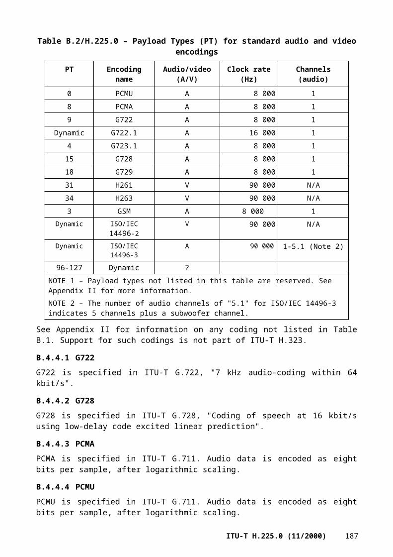
...}
UsageRequest ::= SEQUENCE{
callInfo CallInformation,usageSpec UsageSpecification,...
}
UsageConfirmation ::= SEQUENCE{
...}
UsageRejection ::= SEQUENCE{
reason UsageRejectReason,...
}
UsageIndication ::= SEQUENCE{
callInfo CallInformation,accessTokens SEQUENCE OF AccessToken OPTIONAL,senderRole Role,usageCallStatus UsageCallStatus,srcInfo PartyInformation OPTIONAL,destAddress PartyInformation,startTime TimeStamp OPTIONAL,endTime TimeStamp OPTIONAL,terminationCause TerminationCause OPTIONAL,usageFields SEQUENCE OF UsageField,...
}
UsageField ::= SEQUENCE{
id OBJECT IDENTIFIER,value OCTET STRING,...
}
UsageRejectReason ::= CHOICE{
invalidCall NULL,unavailable NULL,security NULL,noServiceRelationship NULL,undefined NULL,...
}
UsageIndicationConfirmation ::= SEQUENCE{
...}
190 ITU-T H.225.0 (11/2000)

UsageIndicationRejection ::= SEQUENCE{
reason UsageIndicationRejectionReason,...
}
UsageIndicationRejectionReason ::= CHOICE{
unknownCall NULL,incomplete NULL,security NULL,noServiceRelationship NULL,undefined NULL,...
}
ValidationRequest ::= SEQUENCE{
accessToken SEQUENCE OF AccessToken OPTIONAL,destinationInfo PartyInformation OPTIONAL,sourceInfo PartyInformation OPTIONAL,callInfo CallInformation,usageSpec UsageSpecification OPTIONAL,...
}
ValidationConfirmation ::= SEQUENCE{
destinationInfo PartyInformation OPTIONAL,usageSpec UsageSpecification OPTIONAL,...
}
ValidationRejection ::= SEQUENCE{
reason ValidationRejectionReason,...
}
ValidationRejectionReason ::= CHOICE{
tokenNotValid NULL,security NULL, -- request did not meet security requirementshopCountExceeded NULL,missingSorceInfo NULL, missingDestInfo NULL,noServiceRelationship NULL,undefined NULL,...
}
RequestInProgress ::= SEQUENCE{
delay INTEGER (1..65535),...
}
ITU-T H.225.0 (11/2000) 191
NonStandardRequest ::= SEQUENCE{
...}
NonStandardConfirmation ::= SEQUENCE{
...}
NonStandardRejection ::= SEQUENCE{
reason NonStandardRejectionReason,...
}
NonStandardRejectionReason ::= CHOICE{
notSupported NULL,noServiceRelationship NULL,undefined NULL,...
}
UnknownMessageResponse ::= SEQUENCE{
unknownMessage OCTET STRING,reason UnknownMessageReason,...
}
UnknownMessageReason ::= CHOICE{
notUnderstood NULL,undefined NULL,...
}
---- structures common to multiple messages--
AddressTemplate ::= SEQUENCE{
pattern SEQUENCE OF Pattern,routeInfo SEQUENCE OF RouteInformation,timeToLive INTEGER (1..4294967295),...
}
Pattern ::= CHOICE{
specific AliasAddress,wildcard AliasAddress,range SEQUENCE {
192 ITU-T H.225.0 (11/2000)

startOfRange PartyNumber,endOfRange PartyNumber
},...
}
RouteInformation ::= SEQUENCE{
messageType CHOICE{
sendAccessRequest NULL,sendSetup NULL,nonExistent NULL,...
},callSpecific BOOLEAN,usageSpec UsageSpecification OPTIONAL,priceInfo SEQUENCE OF PriceInfoSpec OPTIONAL,contacts SEQUENCE OF ContactInformation,type EndpointType OPTIONAL,
-- must be present if messageType = sendSetup...}
ContactInformation ::= SEQUENCE{ transportAddress AliasAddress, priorityINTEGER (0..127), transportQoS TransportQOS OPTIONAL,
security SEQUENCE OF SecurityMode OPTIONAL,accessTokens SEQUENCE OF AccessToken OPTIONAL,
...}
PriceInfoSpec ::= SEQUENCE{
currency IA5String (SIZE(3)), -- e.g. "USD"currencyScale INTEGER(-127..127),validFrom GlobalTimeStamp OPTIONAL,validUntil GlobalTimeStamp OPTIONAL,hoursFrom IA5String (SIZE(6)) OPTIONAL, -- "HHMMSS" UTChoursUntil IA5String (SIZE(6)) OPTIONAL, -- "HHMMSS" UTCpriceElement SEQUENCE OF PriceElement OPTIONAL,priceFormula IA5String (SIZE(1..2048)) OPTIONAL,...
}
PriceElement ::= SEQUENCE{
amount INTEGER(0..4294967295), -- meter incrementquantum INTEGER(0..4294967295), -- each or part
-- thereofunits CHOICE{
seconds NULL,packets NULL,bytes NULL,initial NULL,minimum NULL,maximum NULL,...
},...
}
ITU-T H.225.0 (11/2000) 193

Descriptor ::= SEQUENCE{
descriptorInfo DescriptorInfo,templates SEQUENCE OF AddressTemplate,gatekeeperID GatekeeperIdentifier OPTIONAL,...
}
DescriptorInfo ::= SEQUENCE{
descriptorID DescriptorID,lastChanged GlobalTimeStamp,...
}
AlternateBEInfo ::= SEQUENCE{
alternateBE SEQUENCE OF AlternateBE,alternateIsPermanent BOOLEAN,...
}
AlternateBE ::= SEQUENCE{
contactAddress AliasAddress,priority INTEGER (1..127),elementIdentifier ElementIdentifier OPTIONAL,...
}
AccessToken ::= CHOICE{
token ClearToken,cryptoToken CryptoH323Token,...
}
CallInformation ::= SEQUENCE {
callIdentifier CallIdentifier,conferenceID ConferenceIdentifier,...
}
UsageCallStatus ::= CHOICE{
preConnect NULL, -- Call has not startedcallInProgress NULL, -- Call is in progresscallEnded NULL, -- Call ended...
}
UserInformation ::= SEQUENCE{
userIdentifier AliasAddress,userAuthenticator SEQUENCE OF CryptoH323Token OPTIONAL,...
}
194 ITU-T H.225.0 (11/2000)

UsageSpecification ::= SEQUENCE{
sendTo ElementIdentifier,when SEQUENCE{
never NULL OPTIONAL,start NULL OPTIONAL,end NULL OPTIONAL,period INTEGER(1..65535) OPTIONAL, -- in secondsfailures NULL OPTIONAL,...
},required SEQUENCE OF OBJECT IDENTIFIER,preferred SEQUENCE OF OBJECT IDENTIFIER,...
}
PartyInformation ::= SEQUENCE{
logicalAddresses SEQUENCE OF AliasAddress, domainIdentifier AliasAddress OPTIONAL,transportAddress AliasAddress OPTIONAL,endpointType EndpointType OPTIONAL,userInfo UserInformation OPTIONAL,timeZone TimeZone OPTIONAL,...
}
Role ::= CHOICE{
originator NULL,destination NULL,nonStandardData NonStandardParameter,...
}
TimeZone ::= INTEGER (-43200..43200)-- number of seconds relative to UTC-- including DST if appropriate
TerminationCause ::= SEQUENCE{
releaseCompleteReason ReleaseCompleteReason,causeIE INTEGER (1..65535) OPTIONAL,nonStandardData NonStandardParameter OPTIONAL,...
}
AnnexGVersion ::= OBJECT IDENTIFIER-- shall be set to -- {itu-t (0) recommendation (0) h(8) h225.0(2250)-- Annex (1) G (7) version (0) 1 (0)}
DescriptorID ::= GloballyUniqueID
ElementIdentifier ::= BMPString (SIZE(1..128))
ITU-T H.225.0 (11/2000) 195

GlobalTimeStamp ::= IA5String (SIZE(14)) -- in the form YYYYMMDDHHmmSS-- where YYYY = year, MM = month, DD = day,-- HH = hour, mm = minute, SS = second-- (for example, 19981219120000 for noon-- 19 December 1998)
END -- of ANNEXG-MESSAGES
ANNEX H
H.225.0 message syntax (ASN.1)
This Recommendation defines protocols for RAS (essentially a gatekeeper protocol) and call signalling (essentially protocol data units which reside in a User-user information element). These protocols are defined together in the following ASN.1 tree. Semantic definitions for the messages and various elements appear in previous clauses.
H323-MESSAGES DEFINITIONS AUTOMATIC TAGS ::=BEGIN
IMPORTSSIGNED{},ENCRYPTED{},HASHED{},ChallengeString,TimeStamp,RandomVal,Password,EncodedPwdCertToken,ClearToken,CryptoToken,AuthenticationMechanism
FROM H235-SECURITY-MESSAGESDataProtocolCapability,T38FaxProfile
FROM MULTIMEDIA-SYSTEM-CONTROLPackagesDescriptor,SignalsDescriptor
FROM MEDIA-GATEWAY-CONTROL;
H323-UserInformation ::= SEQUENCE -- root for all Q.931 related ASN.1{
h323-uu-pdu H323-UU-PDU,user-data SEQUENCE{
protocol-discriminator INTEGER (0..255),user-information OCTET STRING (SIZE(1..131)),...
} OPTIONAL,...
}
196 ITU-T H.225.0 (11/2000)

H323-UU-PDU ::= SEQUENCE{
h323-message-body CHOICE{
setup Setup-UUIE,callProceeding CallProceeding-UUIE,connect Connect-UUIE,alerting Alerting-UUIE,information Information-UUIE,releaseComplete ReleaseComplete-UUIE,facility Facility-UUIE,...,progress Progress-UUIE,empty NULL, -- used when a Facility message is sent,
-- but the Facility-UUIE is not to be invoked-- (possible when transporting supplementary-- services messages in versions prior to-- H.225.0 version 4)
status Status-UUIE,statusInquiry StatusInquiry-UUIE,setupAcknowledge SetupAcknowledge-UUIE,notify Notify-UUIE
},nonStandardData NonStandardParameter OPTIONAL,...,h4501SupplementaryService SEQUENCE OF OCTET STRING OPTIONAL,
-- each sequence of octet string is defined as one-- H4501SupplementaryService APDU as defined in-- Table 3/H.450.1
h245Tunneling BOOLEAN,-- if TRUE, tunneling of H.245 messages is enabled
h245Control SEQUENCE OF OCTET STRING OPTIONAL,nonStandardControl SEQUENCE OF NonStandardParameter OPTIONAL,callLinkage CallLinkage OPTIONAL,
tunnelledSignallingMessage SEQUENCE{
tunnelledProtocolID TunnelledProtocol, -- tunnelled signalling protocol IDmessageContent SEQUENCE OF OCTET STRING, -- sequence of entire
-- message(s)tunnellingRequired NULL OPTIONAL,nonStandardData NonStandardParameter OPTIONAL,...
} OPTIONAL,provisionalRespToH245Tunneling NULL OPTIONAL,stimulusControl StimulusControl OPTIONAL,genericData SEQUENCE OF GenericData OPTIONAL
}
StimulusControl ::= SEQUENCE{
nonStandard NonStandardParameter OPTIONAL,isText NULL OPTIONAL,h248Message OCTET STRING OPTIONAL,...
}
Alerting-UUIE ::= SEQUENCE{
protocolIdentifier ProtocolIdentifier,destinationInfo EndpointType,h245Address TransportAddress OPTIONAL,...,callIdentifier CallIdentifier,
ITU-T H.225.0 (11/2000) 197

h245SecurityMode H245Security OPTIONAL,tokens SEQUENCE OF ClearToken OPTIONAL,cryptoTokens SEQUENCE OF CryptoH323Token OPTIONAL,fastStart SEQUENCE OF OCTET STRING OPTIONAL,multipleCalls BOOLEAN,maintainConnection BOOLEAN,alertingAddress SEQUENCE OF AliasAddress OPTIONAL,presentationIndicator PresentationIndicator OPTIONAL,screeningIndicator ScreeningIndicator OPTIONAL,fastConnectRefused NULL OPTIONAL,serviceControl SEQUENCE OF ServiceControlSession OPTIONAL,capacity CallCapacity OPTIONAL,featureSet FeatureSet OPTIONAL
}
CallProceeding-UUIE ::= SEQUENCE{
protocolIdentifier ProtocolIdentifier,destinationInfo EndpointType,h245Address TransportAddress OPTIONAL,...,callIdentifier CallIdentifier,h245SecurityMode H245Security OPTIONAL,tokens SEQUENCE OF ClearToken OPTIONAL,cryptoTokens SEQUENCE OF CryptoH323Token OPTIONAL,fastStart SEQUENCE OF OCTET STRING OPTIONAL,multipleCalls BOOLEAN,maintainConnection BOOLEAN,fastConnectRefused NULL OPTIONAL,featureSet FeatureSet OPTIONAL
}
Connect-UUIE ::= SEQUENCE{
protocolIdentifier ProtocolIdentifier,h245Address TransportAddress OPTIONAL,destinationInfo EndpointType,conferenceID ConferenceIdentifier,...,callIdentifier CallIdentifier,h245SecurityMode H245Security OPTIONAL,tokens SEQUENCE OF ClearToken OPTIONAL,cryptoTokens SEQUENCE OF CryptoH323Token OPTIONAL,fastStart SEQUENCE OF OCTET STRING OPTIONAL,multipleCalls BOOLEAN,maintainConnection BOOLEAN,language SEQUENCE OF IA5String (SIZE (1..32)) OPTIONAL,
-- RFC1766 language tagconnectedAddress SEQUENCE OF AliasAddress OPTIONAL,presentationIndicator PresentationIndicator OPTIONAL,screeningIndicator ScreeningIndicator OPTIONAL,fastConnectRefused NULL OPTIONAL,serviceControl SEQUENCE OF ServiceControlSession OPTIONAL,capacity CallCapacity OPTIONAL,featureSet FeatureSet OPTIONAL
}
Information-UUIE ::=SEQUENCE{
protocolIdentifier ProtocolIdentifier,...,callIdentifier CallIdentifier,tokens SEQUENCE OF ClearToken OPTIONAL,cryptoTokens SEQUENCE OF CryptoH323Token OPTIONAL,
198 ITU-T H.225.0 (11/2000)
fastStart SEQUENCE OF OCTET STRING OPTIONAL,fastConnectRefused NULL OPTIONAL,circuitInfo CircuitInfo OPTIONAL
}
ReleaseComplete-UUIE ::= SEQUENCE{
protocolIdentifier ProtocolIdentifier,reason ReleaseCompleteReason OPTIONAL,...,callIdentifier CallIdentifier,tokens SEQUENCE OF ClearToken OPTIONAL,cryptoTokens SEQUENCE OF CryptoH323Token OPTIONAL,busyAddress SEQUENCE OF AliasAddress OPTIONAL,presentationIndicator PresentationIndicator OPTIONAL,screeningIndicator ScreeningIndicator OPTIONAL,capacity CallCapacity OPTIONAL,serviceControl SEQUENCE OF ServiceControlSession OPTIONAL,featureSet FeatureSet OPTIONAL
}
ReleaseCompleteReason ::= CHOICE{
noBandwidth NULL, -- bandwidth taken away or ARQ deniedgatekeeperResources NULL, -- exhaustedunreachableDestination NULL, -- no transport path to the destinationdestinationRejection NULL, -- rejected at destinationinvalidRevision NULL,noPermission NULL, -- called party's gatekeeper rejectsunreachableGatekeeper NULL, -- terminal cannot reach gatekeeper
-- for ARQgatewayResources NULL,badFormatAddress NULL,adaptiveBusy NULL, -- call is dropping due to LAN crowdinginConf NULL, -- no address in AlternativeAddressundefinedReason NULL,...,facilityCallDeflection NULL, -- call was deflected using a Facility
-- messagesecurityDenied NULL, -- incompatible security settingscalledPartyNotRegistered NULL, -- used by gatekeeper when endpoint has
-- preGrantedARQ to bypass ARQ/ACFcallerNotRegistered NULL, -- used by gatekeeper when endpoint has
-- preGrantedARQ to bypass ARQ/ACFnewConnectionNeeded NULL, -- indicates that the Setup was not
-- accepted on this connection, but that -- the Setup may be accepted on-- a new connection
nonStandardReason NonStandardParameter,replaceWithConferenceInvite ConferenceIdentifier, -- call dropped due to
-- subsequent invitation-- to a conference -- (see H.323 8.4.3.8)
genericDataReason NULL,neededFeatureNotSupported NULL,tunnelledSignallingRejected NULL
}
Setup-UUIE ::= SEQUENCE{
protocolIdentifier ProtocolIdentifier,h245Address TransportAddress OPTIONAL,sourceAddress SEQUENCE OF AliasAddress OPTIONAL,sourceInfo EndpointType,
ITU-T H.225.0 (11/2000) 199

destinationAddress SEQUENCE OF AliasAddress OPTIONAL,destCallSignalAddress TransportAddress OPTIONAL,destExtraCallInfo SEQUENCE OF AliasAddress OPTIONAL, -- Note 1 destExtraCRV SEQUENCE OF CallReferenceValue OPTIONAL, -- Note 1activeMC BOOLEAN,conferenceID ConferenceIdentifier,conferenceGoal CHOICE{
create NULL,join NULL,invite NULL,...,capability-negotiation NULL,callIndependentSupplementaryService NULL
},callServices QseriesOptions OPTIONAL,callType CallType,...,sourceCallSignalAddress TransportAddress OPTIONAL,remoteExtensionAddress AliasAddress OPTIONAL,callIdentifier CallIdentifier,h245SecurityCapability SEQUENCE OF H245Security OPTIONAL,tokens SEQUENCE OF ClearToken OPTIONAL,cryptoTokens SEQUENCE OF CryptoH323Token OPTIONAL,fastStart SEQUENCE OF OCTET STRING OPTIONAL,mediaWaitForConnect BOOLEAN,canOverlapSend BOOLEAN,endpointIdentifier EndpointIdentifier OPTIONAL,multipleCalls BOOLEAN,maintainConnection BOOLEAN,connectionParameters SEQUENCE -- additional gateway parameters{
connectionType ScnConnectionType,numberOfScnConnections INTEGER (0..65535),connectionAggregation ScnConnectionAggregation,...
} OPTIONAL,language SEQUENCE OF IA5String (SIZE (1..32)) OPTIONAL,
-- RFC1766 language tagpresentationIndicator PresentationIndicator OPTIONAL,screeningIndicator ScreeningIndicator OPTIONAL,serviceControl SEQUENCE OF ServiceControlSession OPTIONAL,symmetricOperationRequired NULL OPTIONAL,capacity CallCapacity OPTIONAL,circuitInfo CircuitInfo OPTIONAL,desiredProtocols SEQUENCE OF SupportedProtocols OPTIONAL,neededFeatures SEQUENCE OF FeatureDescriptor OPTIONAL,desiredFeatures SEQUENCE OF FeatureDescriptor OPTIONAL,supportedFeatures SEQUENCE OF FeatureDescriptor OPTIONAL,parallelH245Control SEQUENCE OF OCTET STRING OPTIONAL,additionalSourceAddresses SEQUENCE OF ExtendedAliasAddress OPTIONAL
}
ScnConnectionType ::= CHOICE{
unknown NULL, -- should be seleceted when connection type is unknownbChannel NULL, -- each individual connection on the SCN is 64kbps.
-- Note that where SCN delivers 56kbps usable data, the -- actual bandwidth allocated on SCN is still 64kbps.
hybrid2x64 NULL, -- each connection is a 128kbps hybrid callhybrid384 NULL, -- each connection is an H0 (384kbps) hybrid callhybrid1536 NULL, -- each connection is an H11 (1536kbps) hybrid callhybrid1920 NULL, -- each connection is an H12 (1920kbps) hybrid callmultirate NULL, -- bandwidth supplied by SCN using multirate.
200 ITU-T H.225.0 (11/2000)

-- In this case, the information transfer rate octet in -- the bearer capability shall be set to multirate and -- the rate multiplier octet shall denote the number -- of B channels.
...}
ScnConnectionAggregation ::= CHOICE{
auto NULL, -- aggregation mechanism is unknownnone NULL, -- call produced using a single SCN connectionh221 NULL, -- use H.221 framing to aggregate the connectionsbonded-mode1 NULL, -- use ISO/IEC 13871 bonding mode 1.
-- Use bonded-mode1 to signal a bonded call if the -- precise bonding mode to be used is unknown.
bonded-mode2 NULL, -- use ISO/IEC 13871 bonding mode 2bonded-mode3 NULL, -- use ISO/IEC 13871 bonding mode 3...
}
PresentationIndicator ::= CHOICE{
presentationAllowed NULL,presentationRestricted NULL,addressNotAvailable NULL,...
}
ScreeningIndicator ::= ENUMERATED{
userProvidedNotScreened (0),-- number was provided by a remote user-- and has not been screened by a gatekeeper
userProvidedVerifiedAndPassed (1),-- number was provided by user-- equipment (or by a remote network), and has-- been screened by a gatekeeper
userProvidedVerifiedAndFailed (2),-- number was provided by user-- equipment (or by a remote network), and the-- gatekeeper has determined that the -- information is incorrect
networkProvided (3),-- number was provided by a gatekeeper
...}
Facility-UUIE ::= SEQUENCE{
protocolIdentifier ProtocolIdentifier,alternativeAddress TransportAddress OPTIONAL,alternativeAliasAddress SEQUENCE OF AliasAddress OPTIONAL,conferenceID ConferenceIdentifier OPTIONAL,reason FacilityReason,...,callIdentifier CallIdentifier,destExtraCallInfo SEQUENCE OF AliasAddress OPTIONAL,remoteExtensionAddress AliasAddress OPTIONAL,tokens SEQUENCE OF ClearToken OPTIONAL,cryptoTokens SEQUENCE OF CryptoH323Token OPTIONAL,conferences SEQUENCE OF ConferenceList OPTIONAL,h245Address TransportAddress OPTIONAL,fastStart SEQUENCE OF OCTET STRING OPTIONAL,multipleCalls BOOLEAN,
ITU-T H.225.0 (11/2000) 201

maintainConnection BOOLEAN,fastConnectRefused NULL OPTIONAL,serviceControl SEQUENCE OF ServiceControlSession OPTIONAL,circuitInfo CircuitInfo OPTIONAL,featureSet FeatureSet OPTIONAL,destinationInfo EndpointType OPTIONAL,h245SecurityMode H245Security OPTIONAL
}
ConferenceList ::= SEQUENCE{
conferenceID ConferenceIdentifier OPTIONAL,conferenceAlias AliasAddress OPTIONAL,nonStandardData NonStandardParameter OPTIONAL,...
}
FacilityReason ::= CHOICE{
routeCallToGatekeeper NULL, -- call must use gatekeeper model-- gatekeeper is alternativeAddress
callForwarded NULL,routeCallToMC NULL,undefinedReason NULL,...,conferenceListChoice NULL,startH245 NULL, -- recipient should connect to h245AddressnoH245 NULL, -- endpoint does not support H.245newTokens NULL,featureSetUpdate NULL,forwardedElements NULL,transportedInformation NULL
}
Progress-UUIE ::= SEQUENCE{
protocolIdentifier ProtocolIdentifier,destinationInfo EndpointType,h245Address TransportAddress OPTIONAL,callIdentifier CallIdentifier,h245SecurityMode H245Security OPTIONAL,tokens SEQUENCE OF ClearToken OPTIONAL,cryptoTokens SEQUENCE OF CryptoH323Token OPTIONAL,fastStart SEQUENCE OF OCTET STRING OPTIONAL,...,multipleCalls BOOLEAN,maintainConnection BOOLEAN,fastConnectRefused NULL OPTIONAL
}
TransportAddress ::= CHOICE{
ipAddress SEQUENCE{
ip OCTET STRING (SIZE(4)),port INTEGER(0..65535)
},ipSourceRoute SEQUENCE{
ip OCTET STRING (SIZE(4)),port INTEGER(0..65535),route SEQUENCE OF OCTET STRING (SIZE(4)),routing CHOICE{
202 ITU-T H.225.0 (11/2000)

strict NULL,loose NULL,...
},...
},ipxAddress SEQUENCE{
node OCTET STRING (SIZE(6)),netnum OCTET STRING (SIZE(4)),port OCTET STRING (SIZE(2))
},ip6Address SEQUENCE{
ip OCTET STRING (SIZE(16)),port INTEGER(0..65535),...
},netBios OCTET STRING (SIZE(16)),nsap OCTET STRING (SIZE(1..20)),nonStandardAddress NonStandardParameter,...
}
Status-UUIE ::= SEQUENCE{
protocolIdentifier ProtocolIdentifier,callIdentifier CallIdentifier,tokens SEQUENCE OF ClearToken OPTIONAL,cryptoTokens SEQUENCE OF CryptoH323Token OPTIONAL,...
}
StatusInquiry-UUIE ::= SEQUENCE{
protocolIdentifier ProtocolIdentifier,callIdentifier CallIdentifier,tokens SEQUENCE OF ClearToken OPTIONAL,cryptoTokens SEQUENCE OF CryptoH323Token OPTIONAL,...
}
SetupAcknowledge-UUIE ::= SEQUENCE{
protocolIdentifier ProtocolIdentifier,callIdentifier CallIdentifier,tokens SEQUENCE OF ClearToken OPTIONAL,cryptoTokens SEQUENCE OF CryptoH323Token OPTIONAL,...
}
Notify-UUIE ::= SEQUENCE{
protocolIdentifier ProtocolIdentifier,callIdentifier CallIdentifier,tokens SEQUENCE OF ClearToken OPTIONAL,cryptoTokens SEQUENCE OF CryptoH323Token OPTIONAL,...
}
-- Beginning of common message elements section
EndpointType ::= SEQUENCE{
ITU-T H.225.0 (11/2000) 203

nonStandardData NonStandardParameter OPTIONAL,vendor VendorIdentifier OPTIONAL,gatekeeper GatekeeperInfo OPTIONAL,gateway GatewayInfo OPTIONAL,mcu McuInfo OPTIONAL, -- mc must be set as wellterminal TerminalInfo OPTIONAL,mc BOOLEAN, -- shall not be set by itselfundefinedNode BOOLEAN,...,set BIT STRING (SIZE(32)) OPTIONAL,
-- shall not be used with mc, gatekeeper-- code points for the various SET devices-- are defined in the respective SET Annexes
supportedTunnelledProtocols SEQUENCE OF TunnelledProtocol OPTIONAL-- list of supported tunnelled protocols
}
GatewayInfo ::= SEQUENCE{
protocol SEQUENCE OF SupportedProtocols OPTIONAL,nonStandardData NonStandardParameter OPTIONAL,...
}
SupportedProtocols ::= CHOICE{
nonStandardData NonStandardParameter,h310 H310Caps,h320 H320Caps,h321 H321Caps,h322 H322Caps,h323 H323Caps,h324 H324Caps,voice VoiceCaps,t120-only T120OnlyCaps,...,nonStandardProtocol NonStandardProtocol,t38FaxAnnexbOnly T38FaxAnnexbOnlyCaps
}
H310Caps ::= SEQUENCE{
nonStandardData NonStandardParameter OPTIONAL,...,dataRatesSupported SEQUENCE OF DataRate OPTIONAL,supportedPrefixes SEQUENCE OF SupportedPrefix
}
H320Caps ::= SEQUENCE{
nonStandardData NonStandardParameter OPTIONAL,...,dataRatesSupported SEQUENCE OF DataRate OPTIONAL,supportedPrefixes SEQUENCE OF SupportedPrefix
}
H321Caps ::= SEQUENCE{
nonStandardData NonStandardParameter OPTIONAL,...,dataRatesSupported SEQUENCE OF DataRate OPTIONAL,supportedPrefixes SEQUENCE OF SupportedPrefix
}
204 ITU-T H.225.0 (11/2000)

H322Caps ::= SEQUENCE{
nonStandardData NonStandardParameter OPTIONAL,...,dataRatesSupported SEQUENCE OF DataRate OPTIONAL,supportedPrefixes SEQUENCE OF SupportedPrefix
}
H323Caps ::= SEQUENCE{
nonStandardData NonStandardParameter OPTIONAL,...,dataRatesSupported SEQUENCE OF DataRate OPTIONAL,supportedPrefixes SEQUENCE OF SupportedPrefix
}
H324Caps ::= SEQUENCE{
nonStandardData NonStandardParameter OPTIONAL,...,dataRatesSupported SEQUENCE OF DataRate OPTIONAL,supportedPrefixes SEQUENCE OF SupportedPrefix
}
VoiceCaps ::= SEQUENCE{
nonStandardData NonStandardParameter OPTIONAL,...,dataRatesSupported SEQUENCE OF DataRate OPTIONAL,supportedPrefixes SEQUENCE OF SupportedPrefix
}
T120OnlyCaps ::= SEQUENCE{
nonStandardData NonStandardParameter OPTIONAL,...,dataRatesSupported SEQUENCE OF DataRate OPTIONAL,supportedPrefixes SEQUENCE OF SupportedPrefix
}
NonStandardProtocol ::= SEQUENCE{
nonStandardData NonStandardParameter OPTIONAL,dataRatesSupported SEQUENCE OF DataRate OPTIONAL,supportedPrefixes SEQUENCE OF SupportedPrefix,...
}
T38FaxAnnexbOnlyCaps ::= SEQUENCE{
nonStandardData NonStandardParameter OPTIONAL,dataRatesSupported SEQUENCE OF DataRate OPTIONAL,supportedPrefixes SEQUENCE OF SupportedPrefix,t38FaxProtocol DataProtocolCapability,t38FaxProfile T38FaxProfile,...
}
McuInfo ::= SEQUENCE{
nonStandardData NonStandardParameter OPTIONAL,...,protocol SEQUENCE OF SupportedProtocols OPTIONAL
}
ITU-T H.225.0 (11/2000) 205

TerminalInfo ::= SEQUENCE {
nonStandardData NonStandardParameter OPTIONAL,...
}
GatekeeperInfo ::= SEQUENCE {
nonStandardData NonStandardParameter OPTIONAL,...
}
VendorIdentifier ::= SEQUENCE{
vendor H221NonStandard,productId OCTET STRING (SIZE(1..256)) OPTIONAL, -- per vendorversionId OCTET STRING (SIZE(1..256)) OPTIONAL, -- per product...
}
H221NonStandard ::= SEQUENCE{ t35CountryCode INTEGER(0..255),
t35Extension INTEGER(0..255),manufacturerCode INTEGER(0..65535),...
}
TunnelledProtocol ::= SEQUENCE{
id CHOICE{tunnelledProtocolObjectID OBJECT IDENTIFIER,
tunnelledProtocolAlternateID TunnelledProtocolAlternateIdentifier,...
},subIdentifier IA5String (SIZE (1..64)) OPTIONAL,...
}
TunnelledProtocolAlternateIdentifier ::= SEQUENCE{
protocolType IA5String (SIZE (1..64)),protocolVariant IA5String (SIZE (1..64)) OPTIONAL,...
}
NonStandardParameter ::= SEQUENCE{
nonStandardIdentifier NonStandardIdentifier,data OCTET STRING
}
NonStandardIdentifier ::= CHOICE{
object OBJECT IDENTIFIER,h221NonStandard H221NonStandard,...
}
AliasAddress ::= CHOICE{
dialedDigits IA5String (SIZE (1..128)) (FROM ("0123456789#*,")),h323-ID BMPString (SIZE (1..256)), -- Basic ISO/IEC 10646-1 (Unicode)
206 ITU-T H.225.0 (11/2000)
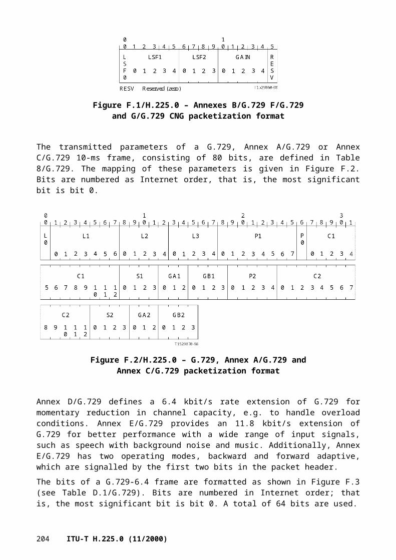
...,url-ID IA5String (SIZE(1..512)), -- URL style addresstransportID TransportAddress,email-ID IA5String (SIZE(1..512)), -- rfc822-compliant email addresspartyNumber PartyNumber,mobileUIM MobileUIM
}
AddressPattern ::= CHOICE{wildcard AliasAddress,range SEQUENCE{startOfRange PartyNumber,endOfRange PartyNumber},...}
PartyNumber ::= CHOICE{
e164Number PublicPartyNumber,-- the numbering plan is according to-- Recommendations E.163 and E.164.
dataPartyNumber NumberDigits,-- not used, value reserved.
telexPartyNumber NumberDigits,-- not used, value reserved.
privateNumber PrivatePartyNumber,-- the numbering plan is according to -- ISO/IEC 11571.
nationalStandardPartyNumber NumberDigits,-- not used, value reserved.
...}
PublicPartyNumber ::= SEQUENCE{
publicTypeOfNumber PublicTypeOfNumber,publicNumberDigits NumberDigits
}
PrivatePartyNumber ::= SEQUENCE{
privateTypeOfNumber PrivateTypeOfNumber,privateNumberDigits NumberDigits
}
NumberDigits ::= IA5String (SIZE (1..128)) (FROM ("0123456789#*,"))
PublicTypeOfNumber ::= CHOICE{
unknown NULL,-- if used number digits carry prefix -- indicating type-- of number according to national -- recommendations.
internationalNumber NULL,nationalNumber NULL,networkSpecificNumber NULL,
-- not used, value reservedsubscriberNumber NULL,abbreviatedNumber NULL,
ITU-T H.225.0 (11/2000) 207

-- valid only for called party number at -- the outgoing access, network substitutes-- appropriate number.
...}
PrivateTypeOfNumber ::= CHOICE{
unknown NULL,level2RegionalNumber NULL,level1RegionalNumber NULL,pISNSpecificNumber NULL,localNumber NULL,abbreviatedNumber NULL,...
}
MobileUIM ::= CHOICE{
ansi-41-uim ANSI-41-UIM, -- Americas standards Wireless Networksgsm-uim GSM-UIM, -- European standards Wireless Networks...
}
TBCD-STRING ::= IA5String (FROM ("0123456789#*abc"))
ANSI-41-UIM ::= SEQUENCE{
imsi TBCD-STRING (SIZE (3..16)) OPTIONAL,min TBCD-STRING (SIZE (3..16)) OPTIONAL,mdn TBCD-STRING (SIZE (3..16)) OPTIONAL, msisdn TBCD-STRING (SIZE (3..16)) OPTIONAL,esn TBCD-STRING (SIZE (16)) OPTIONAL,mscid TBCD-STRING (SIZE (3..16)) OPTIONAL,system-id CHOICE {
sid TBCD–STRING (SIZE (1..4)),mid TBCD–STRING (SIZE (1..4)),...
}, systemMyTypeCode OCTET STRING (SIZE (1)) OPTIONAL,systemAccessType OCTET STRING (SIZE (1)) OPTIONAL,qualificationInformationCode OCTET STRING (SIZE (1)) OPTIONAL,sesn TBCD-STRING (SIZE (16)) OPTIONAL,soc TBCD-STRING (SIZE (3..16)) OPTIONAL,...-- IMSI refers to International Mobile Station Identification-- MIN refers to Mobile Identification Number-- MDN refers to Mobile Directory Number-- MSISDN refers to Mobile Station ISDN number-- ESN Refers to Electronic Serial Number -- MSCID refers to Mobile Switching Center number + Market ID or System ID-- SID refers to System Identification and MID refers to Market -- Identification-- SystemMyTypeCode refers to vendor identification number-- SystemAccessType refers to the system access type like power down -- registration or call-- origination or Short Message response etc.-- Qualification Information Code refers to the validity-- SESN Refers to SIM Electronic Serial Number for Security purposes of User -- Identification -- SOC refers to System Operator Code
}
208 ITU-T H.225.0 (11/2000)

GSM-UIM ::= SEQUENCE{
imsi TBCD-STRING (SIZE (3..16)) OPTIONAL,tmsi OCTET STRING (SIZE (1..4)) OPTIONAL,msisdn TBCD-STRING (SIZE (3..16)) OPTIONAL,imei TBCD-STRING (SIZE (15..16)) OPTIONAL,hplmn TBCD-STRING (SIZE (1..4)) OPTIONAL,vplmn TBCD-STRING (SIZE (1..4)) OPTIONAL,-- IMSI refers to International Mobile Station Identification-- MSISDN refers to Mobile Station ISDN number-- IMEI Refers to International Mobile Equipment Identification -- VPLMN or HPLMN refers to Visiting or Home Public Land Mobile Network -- number...
}
ExtendedAliasAddress ::= SEQUENCE{
address AliasAddress,presentationIndicator PresentationIndicator OPTIONAL,screeningIndicator ScreeningIndicator OPTIONAL,...
}
Endpoint ::= SEQUENCE{
nonStandardData NonStandardParameter OPTIONAL, aliasAddress SEQUENCE OF AliasAddress OPTIONAL, callSignalAddress SEQUENCE OF TransportAddress OPTIONAL, rasAddress SEQUENCE OF TransportAddress OPTIONAL, endpointType EndpointType OPTIONAL, tokens SEQUENCE OF ClearToken OPTIONAL, cryptoTokens SEQUENCE OF CryptoH323Token OPTIONAL,priority INTEGER(0..127) OPTIONAL, remoteExtensionAddress SEQUENCE OF AliasAddress OPTIONAL,destExtraCallInfo SEQUENCE OF AliasAddress OPTIONAL,...,alternateTransportAddresses AlternateTransportAddresses OPTIONAL
}
AlternateTransportAddresses ::= SEQUENCE{
annexE SEQUENCE OF TransportAddress OPTIONAL,...
}
UseSpecifiedTransport ::= CHOICE{
tcp NULL,annexE NULL,...
} AlternateGK ::= SEQUENCE{
rasAddress TransportAddress,gatekeeperIdentifier GatekeeperIdentifier OPTIONAL,needToRegister BOOLEAN,priority INTEGER (0..127),...
}
ITU-T H.225.0 (11/2000) 209

AltGKInfo ::=SEQUENCE{
alternateGatekeeper SEQUENCE OF AlternateGK,altGKisPermanent BOOLEAN,...
}
SecurityServiceMode ::= CHOICE {nonStandard NonStandardParameter,none NULL,default NULL,... -- can be extended with other specific modes}
SecurityCapabilities ::= SEQUENCE {
nonStandard NonStandardParameter OPTIONAL,encryption SecurityServiceMode,authenticaton SecurityServiceMode,integrity SecurityServiceMode,
...}
H245Security ::= CHOICE {
nonStandard NonStandardParameter,noSecurity NULL,tls SecurityCapabilities,ipsec SecurityCapabilities,...
}
QseriesOptions ::= SEQUENCE{
q932Full BOOLEAN, -- if true, indicates full support for Q.932q951Full BOOLEAN, -- if true, indicates full support for Q.951q952Full BOOLEAN, -- if true, indicates full support for Q.952q953Full BOOLEAN, -- if true, indicates full support for Q.953q955Full BOOLEAN, -- if true, indicates full support for Q.955q956Full BOOLEAN, -- if true, indicates full support for Q.956q957Full BOOLEAN, -- if true, indicates full support for Q.957q954Info Q954Details,...
}
Q954Details ::= SEQUENCE{
conferenceCalling BOOLEAN,threePartyService BOOLEAN,...
}
GloballyUniqueID ::= OCTET STRING (SIZE(16))ConferenceIdentifier ::= GloballyUniqueIDRequestSeqNum ::= INTEGER (1..65535)GatekeeperIdentifier ::= BMPString (SIZE(1..128))BandWidth ::= INTEGER (0..4294967295) -- in 100s of bitsCallReferenceValue ::= INTEGER (0..65535)EndpointIdentifier ::= BMPString (SIZE(1..128))ProtocolIdentifier ::= OBJECT IDENTIFIERTimeToLive ::= INTEGER (1..4294967295) -- in secondsH248PackagesDescriptor ::= PackagesDescriptor
210 ITU-T H.225.0 (11/2000)

H248SignalsDescriptor ::= SignalsDescriptorFeatureDescriptor ::= GenericData
CallIdentifier ::= SEQUENCE{
guid GloballyUniqueID,...
}
EncryptIntAlg ::= CHOICE{ -- core encryption algorithms for RAS message integrity
nonStandard NonStandardParameter,isoAlgorithm OBJECT IDENTIFIER, -- defined in ISO/IEC 9979...
}NonIsoIntegrityMechanism ::= CHOICE { -- HMAC mechanism used, no truncation, tagging may be necessary!
hMAC-MD5 NULL,hMAC-iso10118-2-s EncryptIntAlg, -- according to ISO/IEC 10118-2 using
-- EncryptIntAlg as core block -- encryption algorithm (short MAC)
hMAC-iso10118-2-l EncryptIntAlg, -- according to ISO/IEC 10118-2 using-- EncryptIntAlg as core block -- encryption algorithm (long MAC)
hMAC-iso10118-3 OBJECT IDENTIFIER, -- according to ISO/IEC 10118-3 using-- OID as hash function (OID is SHA-1,-- RIPE-MD160,-- RIPE-MD128)
...}
IntegrityMechanism ::= CHOICE{ -- for RAS message integrity
nonStandard NonStandardParameter,digSig NULL, -- indicates to apply a digital signatureiso9797 OBJECT IDENTIFIER, -- according to ISO/IEC 9797 using OID as
-- core encryption algorithm (X-CBC MAC)nonIsoIM NonIsoIntegrityMechanism,...
}
ICV ::= SEQUENCE{
algorithmOID OBJECT IDENTIFIER, -- the algorithm used to compute the -- signature
icv BIT STRING -- the computed cryptographic -- integrity check value or signature
}
FastStartToken ::= ClearToken (WITH COMPONENTS {..., timeStamp PRESENT, dhkey PRESENT, generalID PRESENT
-- set to "alias" -- })EncodedFastStartToken ::= TYPE-IDENTIFIER.&Type (FastStartToken)CryptoH323Token::= CHOICE{
cryptoEPPwdHash SEQUENCE{
alias AliasAddress, -- alias of entity generating hashtimeStamp TimeStamp, -- timestamp used in hashtoken HASHED { EncodedPwdCertToken -- generalID set to
-- "alias" -- }},cryptoGKPwdHash SEQUENCE{
ITU-T H.225.0 (11/2000) 211

gatekeeperId GatekeeperIdentifier, -- GatekeeperID of GK generating -- hash
timeStamp TimeStamp, -- timestamp used in hashtoken HASHED { EncodedPwdCertToken -- generalID set to
-- Gatekeeperid -- }},cryptoEPPwdEncr ENCRYPTED { EncodedPwdCertToken -- generalID set to
-- Gatekeeperid --},cryptoGKPwdEncr ENCRYPTED { EncodedPwdCertToken -- generalID set to
-- Gatekeeperid --},cryptoEPCert SIGNED { EncodedPwdCertToken -- generalID set to
-- Gatekeeperid -- },cryptoGKCert SIGNED { EncodedPwdCertToken -- generalID set to alias -- },cryptoFastStart SIGNED { EncodedFastStartToken },nestedcryptoToken CryptoToken,...
}
DataRate ::= SEQUENCE{
nonStandardData NonStandardParameter OPTIONAL,channelRate BandWidth,channelMultiplier INTEGER (1..256) OPTIONAL,...
}
CallLinkage ::= SEQUENCE{
globalCallId GloballyUniqueID OPTIONAL,threadId GloballyUniqueID OPTIONAL,...
}
SupportedPrefix ::= SEQUENCE{
nonStandardData NonStandardParameter OPTIONAL,prefix AliasAddress,...
}
CapacityReportingCapability ::= SEQUENCE{
canReportCallCapacity BOOLEAN,...
}
CapacityReportingSpecification ::= SEQUENCE{
when SEQUENCE{
callStart NULL OPTIONAL,callEnd NULL OPTIONAL,...
},...
}
CallCapacity ::= SEQUENCE{
maximumCallCapacity CallCapacityInfo OPTIONAL,currentCallCapacity CallCapacityInfo OPTIONAL,...
}
212 ITU-T H.225.0 (11/2000)

CallCapacityInfo ::= SEQUENCE{
voiceGwCallsAvailable SEQUENCE OF CallsAvailable OPTIONAL,h310GwCallsAvailable SEQUENCE OF CallsAvailable OPTIONAL,h320GwCallsAvailable SEQUENCE OF CallsAvailable OPTIONAL,h321GwCallsAvailable SEQUENCE OF CallsAvailable OPTIONAL,h322GwCallsAvailable SEQUENCE OF CallsAvailable OPTIONAL,h323GwCallsAvailable SEQUENCE OF CallsAvailable OPTIONAL,h324GwCallsAvailable SEQUENCE OF CallsAvailable OPTIONAL,t120OnlyGwCallsAvailable SEQUENCE OF CallsAvailable OPTIONAL,t38FaxAnnexbOnlyGwCallsAvailable SEQUENCE OF CallsAvailable OPTIONAL,terminalCallsAvailable SEQUENCE OF CallsAvailable OPTIONAL,mcuCallsAvailable SEQUENCE OF CallsAvailable OPTIONAL,...
}
CallsAvailable ::= SEQUENCE{
calls INTEGER (0..4294967295),group IA5String (SIZE (1..128)) OPTIONAL,...
}
CircuitInfo ::= SEQUENCE{
sourceCircuitID CircuitIdentifier OPTIONAL,destinationCircuitID CircuitIdentifier OPTIONAL,genericData SEQUENCE OF GenericData OPTIONAL,...
}
CircuitIdentifier ::= CHOICE{
cic CicInfo,group GroupID,...
}
CicInfo ::= SEQUENCE{
cic SEQUENCE OF OCTET STRING (SIZE (2..4)),pointCode OCTET STRING (SIZE (2..5)),...
}
GroupID ::= SEQUENCE{
member SEQUENCE OF INTEGER (0..65535) OPTIONAL,group IA5String (SIZE (1..128)),...
}
ServiceControlDescriptor ::= CHOICE{
url IA5String (SIZE(0..512)), -- indicates a URL- -- referenced -- protocol/resource
signal H248SignalsDescriptor,nonStandard NonStandardParameter,callCreditServiceControl CallCreditServiceControl,...
}
ITU-T H.225.0 (11/2000) 213

ServiceControlSession ::= SEQUENCE{
sessionId INTEGER (0..255),contents ServiceControlDescriptor OPTIONAL,reason CHOICE{
open NULL,refresh NULL,close NULL,...
},...
}
RasUsageInfoTypes ::= SEQUENCE{
nonStandardUsageTypes SEQUENCE OF NonStandardParameter,startTime NULL OPTIONAL,endTime NULL OPTIONAL,terminationCause NULL OPTIONAL,...
}
RasUsageSpecification ::= SEQUENCE{
when SEQUENCE{
start NULL OPTIONAL,end NULL OPTIONAL,inIrr NULL OPTIONAL,...
},callStartingPoint SEQUENCE{
alerting NULL OPTIONAL,connect NULL OPTIONAL,...
} OPTIONAL,required RasUsageInfoTypes,...
}
RasUsageInformation ::= SEQUENCE{
nonStandardUsageFields SEQUENCE OF NonStandardParameter,alertingTime TimeStamp OPTIONAL,connectTime TimeStamp OPTIONAL,endTime TimeStamp OPTIONAL,...
}
CallTerminationCause ::= CHOICE{
releaseCompleteReason ReleaseCompleteReason,releaseCompleteCauseIE OCTET STRING (SIZE(2..32)),...
}
BandwidthDetails ::= SEQUENCE{
sender BOOLEAN, -- TRUE=sender, FALSE=receivermulticast BOOLEAN, -- TRUE if stream is multicastbandwidth BandWidth, -- Bandwidth used for streamrtcpAddresses TransportChannelInfo, -- RTCP addresses for media stream
214 ITU-T H.225.0 (11/2000)

...}
CallCreditCapability ::= SEQUENCE{
canDisplayAmountString BOOLEAN OPTIONAL,canEnforceDurationLimit BOOLEAN OPTIONAL,...
}
CallCreditServiceControl ::= SEQUENCE{
amountString BMPString (SIZE (1..512)) OPTIONAL, -- (Unicode)billingMode CHOICE{
credit NULL,debit NULL,...
} OPTIONAL,callDurationLimit INTEGER (1..4294967295) OPTIONAL, -- in secondsenforceCallDurationLimit BOOLEAN OPTIONAL,callStartingPoint CHOICE{
alerting NULL,connect NULL,...
} OPTIONAL,...
}
GenericData ::= SEQUENCE{
id GenericIdentifier,parameters SEQUENCE (SIZE (1..512)) OF EnumeratedParameter OPTIONAL,...
}
GenericIdentifier ::= CHOICE{
standard INTEGER(0..16383,...),oid OBJECT IDENTIFIER,nonStandard GloballyUniqueID,...
}
EnumeratedParameter ::= SEQUENCE{
id GenericIdentifier,content Content OPTIONAL,...
}
Content ::= CHOICE{
raw OCTET STRING,text IA5String,unicode BMPString,bool BOOLEAN,number8 INTEGER (0..255),number16 INTEGER (0..65535),number32 INTEGER (0..4294967295),id GenericIdentifier,alias AliasAddress,transport TransportAddress,
ITU-T H.225.0 (11/2000) 215

compound SEQUENCE (SIZE (1..512)) OF EnumeratedParameter,nested SEQUENCE (SIZE (1..16)) OF GenericData,...
}
FeatureSet ::= SEQUENCE{
replacementFeatureSet BOOLEAN,neededFeatures SEQUENCE OF FeatureDescriptor OPTIONAL,desiredFeatures SEQUENCE OF FeatureDescriptor OPTIONAL,supportedFeatures SEQUENCE OF FeatureDescriptor OPTIONAL,...
}
TransportChannelInfo ::= SEQUENCE{
sendAddress TransportAddress OPTIONAL,recvAddress TransportAddress OPTIONAL,...
}
RTPSession ::= SEQUENCE{
rtpAddress TransportChannelInfo,rtcpAddress TransportChannelInfo,cname PrintableString,ssrc INTEGER (1..4294967295),sessionId INTEGER (1..255),associatedSessionIds SEQUENCE OF INTEGER (1..255),...,multicast NULL OPTIONAL,bandwidth BandWidth OPTIONAL
}
RasMessage ::= CHOICE {
gatekeeperRequest GatekeeperRequest,gatekeeperConfirm GatekeeperConfirm,gatekeeperReject GatekeeperReject,registrationRequest RegistrationRequest,registrationConfirm RegistrationConfirm,registrationReject RegistrationReject,unregistrationRequest UnregistrationRequest,unregistrationConfirm UnregistrationConfirm,unregistrationReject UnregistrationReject,admissionRequest AdmissionRequest,admissionConfirm AdmissionConfirm,admissionReject AdmissionReject,bandwidthRequest BandwidthRequest,bandwidthConfirm BandwidthConfirm,bandwidthReject BandwidthReject,disengageRequest DisengageRequest,disengageConfirm DisengageConfirm,disengageReject DisengageReject,locationRequest LocationRequest,locationConfirm LocationConfirm,locationReject LocationReject, infoRequest InfoRequest,infoRequestResponse InfoRequestResponse,nonStandardMessage NonStandardMessage,unknownMessageResponse UnknownMessageResponse,...,requestInProgress RequestInProgress,resourcesAvailableIndicate ResourcesAvailableIndicate,
216 ITU-T H.225.0 (11/2000)

resourcesAvailableConfirm ResourcesAvailableConfirm,infoRequestAck InfoRequestAck,infoRequestNak InfoRequestNak,serviceControlIndication ServiceControlIndication,serviceControlResponse ServiceControlResponse
}
GatekeeperRequest ::= SEQUENCE --(GRQ){
requestSeqNum RequestSeqNum,protocolIdentifier ProtocolIdentifier,nonStandardData NonStandardParameter OPTIONAL,rasAddress TransportAddress,endpointType EndpointType,gatekeeperIdentifier GatekeeperIdentifier OPTIONAL,callServices QseriesOptions OPTIONAL, endpointAlias SEQUENCE OF AliasAddress OPTIONAL,...,alternateEndpoints SEQUENCE OF Endpoint OPTIONAL,tokens SEQUENCE OF ClearToken OPTIONAL,cryptoTokens SEQUENCE OF CryptoH323Token OPTIONAL,authenticationCapability SEQUENCE OF AuthenticationMechanism OPTIONAL,algorithmOIDs SEQUENCE OF OBJECT IDENTIFIER OPTIONAL,integrity SEQUENCE OF IntegrityMechanism OPTIONAL,integrityCheckValue ICV OPTIONAL,supportsAltGK NULL OPTIONAL,featureSet FeatureSet OPTIONAL,genericData SEQUENCE OF GenericData OPTIONAL
}
GatekeeperConfirm ::= SEQUENCE --(GCF){
requestSeqNum RequestSeqNum,protocolIdentifier ProtocolIdentifier,nonStandardData NonStandardParameter OPTIONAL,gatekeeperIdentifier GatekeeperIdentifier OPTIONAL,rasAddress TransportAddress,...,alternateGatekeeper SEQUENCE OF AlternateGK OPTIONAL,authenticationMode AuthenticationMechanism OPTIONAL,tokens SEQUENCE OF ClearToken OPTIONAL,cryptoTokens SEQUENCE OF CryptoH323Token OPTIONAL,algorithmOID OBJECT IDENTIFIER OPTIONAL,integrity SEQUENCE OF IntegrityMechanism OPTIONAL,integrityCheckValue ICV OPTIONAL,featureSet FeatureSet OPTIONAL,genericData SEQUENCE OF GenericData OPTIONAL
}
GatekeeperReject ::= SEQUENCE --(GRJ){
requestSeqNum RequestSeqNum,protocolIdentifier ProtocolIdentifier,nonStandardData NonStandardParameter OPTIONAL,gatekeeperIdentifier GatekeeperIdentifier OPTIONAL,rejectReason GatekeeperRejectReason,...,altGKInfo AltGKInfo OPTIONAL,tokens SEQUENCE OF ClearToken OPTIONAL,cryptoTokens SEQUENCE OF CryptoH323Token OPTIONAL,integrityCheckValue ICV OPTIONAL,featureSet FeatureSet OPTIONAL,
ITU-T H.225.0 (11/2000) 217

genericData SEQUENCE OF GenericData OPTIONAL}
GatekeeperRejectReason ::= CHOICE{
resourceUnavailable NULL,terminalExcluded NULL, -- permission failure, not a resource
-- failureinvalidRevision NULL,undefinedReason NULL,...,securityDenial NULL,genericDataReason NULL,neededFeatureNotSupported NULL
}
RegistrationRequest ::= SEQUENCE --(RRQ){
requestSeqNum RequestSeqNum,protocolIdentifier ProtocolIdentifier,nonStandardData NonStandardParameter OPTIONAL,discoveryComplete BOOLEAN,callSignalAddress SEQUENCE OF TransportAddress,rasAddress SEQUENCE OF TransportAddress,terminalType EndpointType,terminalAlias SEQUENCE OF AliasAddress OPTIONAL,gatekeeperIdentifier GatekeeperIdentifier OPTIONAL,endpointVendor VendorIdentifier,...,alternateEndpoints SEQUENCE OF Endpoint OPTIONAL,timeToLive TimeToLive OPTIONAL,tokens SEQUENCE OF ClearToken OPTIONAL,cryptoTokens SEQUENCE OF CryptoH323Token OPTIONAL,integrityCheckValue ICV OPTIONAL,keepAlive BOOLEAN,endpointIdentifier EndpointIdentifier OPTIONAL,willSupplyUUIEs BOOLEAN,maintainConnection BOOLEAN,alternateTransportAddresses AlternateTransportAddresses OPTIONAL,additiveRegistration NULL OPTIONAL,terminalAliasPattern SEQUENCE OF AddressPattern OPTIONAL,supportsAltGK NULL OPTIONAL,usageReportingCapability RasUsageInfoTypes OPTIONAL,multipleCalls BOOLEAN OPTIONAL,supportedH248Packages SEQUENCE OF H248PackagesDescriptor OPTIONAL,callCreditCapability CallCreditCapability OPTIONAL,capacityReportingCapability CapacityReportingCapability OPTIONAL,capacity CallCapacity OPTIONAL,featureSet FeatureSet OPTIONAL,genericData SEQUENCE OF GenericData OPTIONAL
}
RegistrationConfirm ::= SEQUENCE --(RCF){
requestSeqNum RequestSeqNum,protocolIdentifier ProtocolIdentifier,nonStandardData NonStandardParameter OPTIONAL,callSignalAddress SEQUENCE OF TransportAddress,terminalAlias SEQUENCE OF AliasAddress OPTIONAL,gatekeeperIdentifier GatekeeperIdentifier OPTIONAL,endpointIdentifier EndpointIdentifier,...,alternateGatekeeper SEQUENCE OF AlternateGK OPTIONAL,timeToLive TimeToLive OPTIONAL,
218 ITU-T H.225.0 (11/2000)

tokens SEQUENCE OF ClearToken OPTIONAL,cryptoTokens SEQUENCE OF CryptoH323Token OPTIONAL,integrityCheckValue ICV OPTIONAL,willRespondToIRR BOOLEAN,preGrantedARQ SEQUENCE{
makeCall BOOLEAN,useGKCallSignalAddressToMakeCall BOOLEAN,answerCall BOOLEAN,useGKCallSignalAddressToAnswer BOOLEAN,...,irrFrequencyInCall INTEGER (1..65535) OPTIONAL, -- in seconds;
-- not present -- if GK does-- not want IRRs
totalBandwidthRestriction BandWidth OPTIONAL, -- total limit -- for all -- concurrent calls
alternateTransportAddresses AlternateTransportAddresses OPTIONAL,useSpecifiedTransport UseSpecifiedTransport OPTIONAL
} OPTIONAL,maintainConnection BOOLEAN,serviceControl SEQUENCE OF ServiceControlSession OPTIONAL,supportsAdditiveRegistration NULL OPTIONAL,terminalAliasPattern SEQUENCE OF AddressPattern OPTIONAL,supportedPrefixes SEQUENCE OF SupportedPrefix OPTIONAL,usageSpec SEQUENCE OF RasUsageSpecification OPTIONAL,featureServerAlias AliasAddress OPTIONAL,capacityReportingSpec CapacityReportingSpecification OPTIONAL,featureSet FeatureSet OPTIONAL,genericData SEQUENCE OF GenericData OPTIONAL
}
RegistrationReject ::= SEQUENCE --(RRJ){
requestSeqNum RequestSeqNum,protocolIdentifier ProtocolIdentifier,nonStandardData NonStandardParameter OPTIONAL,rejectReason RegistrationRejectReason,gatekeeperIdentifier GatekeeperIdentifier OPTIONAL,...,altGKInfo AltGKInfo OPTIONAL,tokens SEQUENCE OF ClearToken OPTIONAL,cryptoTokens SEQUENCE OF CryptoH323Token OPTIONAL,integrityCheckValue ICV OPTIONAL,featureSet FeatureSet OPTIONAL,genericData SEQUENCE OF GenericData OPTIONAL
}
RegistrationRejectReason ::= CHOICE{
discoveryRequired NULL,invalidRevision NULL,invalidCallSignalAddress NULL,invalidRASAddress NULL, -- supplied address is invalidduplicateAlias SEQUENCE OF AliasAddress,
-- alias registered to another -- endpoint
invalidTerminalType NULL,undefinedReason NULL,transportNotSupported NULL, -- one or more of the transports...,transportQOSNotSupported NULL, -- endpoint QOS not supportedresourceUnavailable NULL, -- gatekeeper resources exhausted
ITU-T H.225.0 (11/2000) 219

invalidAlias NULL, -- alias not consistent with -- gatekeeper rules
securityDenial NULL,fullRegistrationRequired NULL, -- registration permission has expiredadditiveRegistrationNotSupported NULL,invalidTerminalAliases SEQUENCE
{terminalAlias SEQUENCE OF AliasAddress OPTIONAL,terminalAliasPattern SEQUENCE OF AddressPattern OPTIONAL,supportedPrefixes SEQUENCE OF SupportedPrefix OPTIONAL,...},
genericDataReason NULL,neededFeatureNotSupported NULL
}
UnregistrationRequest ::= SEQUENCE --(URQ){
requestSeqNum RequestSeqNum,callSignalAddress SEQUENCE OF TransportAddress,endpointAlias SEQUENCE OF AliasAddress OPTIONAL,nonStandardData NonStandardParameter OPTIONAL,endpointIdentifier EndpointIdentifier OPTIONAL,...,alternateEndpoints SEQUENCE OF Endpoint OPTIONAL,gatekeeperIdentifier GatekeeperIdentifier OPTIONAL,tokens SEQUENCE OF ClearToken OPTIONAL,cryptoTokens SEQUENCE OF CryptoH323Token OPTIONAL,integrityCheckValue SUnregRequestReason OPTIONAL,endpointAliasPattern SEQUENCE OF AddressPattern OPTIONAL,supportedPrefixes SEQUENCE OF SupportedPrefix OPTIONAL,alternateGatekeeper SEQUENCE OF AlternateGK OPTIONAL,genericData SEQUENCE OF GenericData OPTIONAL
}
UnregRequestReason ::= CHOICE{
reregistrationRequired NULL,ttlExpired NULL,securityDenial NULL,undefinedReason NULL,...,maintenance NULL
}
UnregistrationConfirm ::= SEQUENCE --(UCF){
requestSeqNum RequestSeqNum,nonStandardData NonStandardParameter OPTIONAL,...,tokens SEQUENCE OF ClearToken OPTIONAL,cryptoTokens SEQUENCE OF CryptoH323Token OPTIONAL,integrityCheckValue ICV OPTIONAL,genericData SEQUENCE OF GenericData OPTIONAL
}
UnregistrationReject ::= SEQUENCE --(URJ){
requestSeqNum RequestSeqNum,rejectReason UnregRejectReason,nonStandardData NonStandardParameter OPTIONAL,...,altGKInfo AltGKInfo OPTIONAL,
220 ITU-T H.225.0 (11/2000)

tokens SEQUENCE OF ClearToken OPTIONAL,cryptoTokens SEQUENCE OF CryptoH323Token OPTIONAL,integrityCheckValue ICV OPTIONAL,genericData SEQUENCE OF GenericData OPTIONAL
}
UnregRejectReason ::= CHOICE{
notCurrentlyRegistered NULL,callInProgress NULL,undefinedReason NULL,...,permissionDenied NULL, -- requesting user not allowed to
-- unregister specified usersecurityDenial NULL
}
AdmissionRequest ::= SEQUENCE --(ARQ){
requestSeqNum RequestSeqNum,callType CallType,callModel CallModel OPTIONAL,endpointIdentifier EndpointIdentifier,destinationInfo SEQUENCE OF AliasAddress OPTIONAL, -- Note 1destCallSignalAddress TransportAddress OPTIONAL, -- Note 1destExtraCallInfo SEQUENCE OF AliasAddress OPTIONAL,srcInfo SEQUENCE OF AliasAddress,srcCallSignalAddress TransportAddress OPTIONAL, bandWidth BandWidth,callReferenceValue CallReferenceValue,nonStandardData NonStandardParameter OPTIONAL,callServices QseriesOptions OPTIONAL,conferenceID ConferenceIdentifier,activeMC BOOLEAN,answerCall BOOLEAN, -- answering a call...,canMapAlias BOOLEAN, -- can handle alias addresscallIdentifier CallIdentifier,srcAlternatives SEQUENCE OF Endpoint OPTIONAL,destAlternatives SEQUENCE OF Endpoint OPTIONAL,gatekeeperIdentifier GatekeeperIdentifier OPTIONAL,tokens SEQUENCE OF ClearToken OPTIONAL,cryptoTokens SEQUENCE OF CryptoH323Token OPTIONAL,integrityCheckValue ICV OPTIONAL,transportQOS TransportQOS OPTIONAL,willSupplyUUIEs BOOLEAN,callLinkage CallLinkage OPTIONAL,gatewayDataRate DataRate OPTIONAL,capacity CallCapacity OPTIONAL,circuitInfo CircuitInfo OPTIONAL,desiredProtocols SEQUENCE OF SupportedProtocols OPTIONAL,desiredTunnelledProtocol TunnelledProtocol OPTIONAL,featureSet FeatureSet OPTIONAL,genericData SEQUENCE OF GenericData OPTIONAL
}
CallType ::= CHOICE{
pointToPoint NULL, -- Point-to-pointoneToN NULL, -- no interaction (FFS)nToOne NULL, -- no interaction (FFS)nToN NULL, -- interactive (multipoint)...
}
ITU-T H.225.0 (11/2000) 221
CallModel ::= CHOICE{
direct NULL,gatekeeperRouted NULL,...
}
TransportQOS ::= CHOICE{
endpointControlled NULL,gatekeeperControlled NULL,noControl NULL,...
}
AdmissionConfirm ::= SEQUENCE --(ACF){
requestSeqNum RequestSeqNum,bandWidth BandWidth,callModel CallModel,destCallSignalAddress TransportAddress,irrFrequency INTEGER (1..65535) OPTIONAL,nonStandardData NonStandardParameter OPTIONAL,...,destinationInfo SEQUENCE OF AliasAddress OPTIONAL,destExtraCallInfo SEQUENCE OF AliasAddress OPTIONAL,destinationType EndpointType OPTIONAL,remoteExtensionAddress SEQUENCE OF AliasAddress OPTIONAL,alternateEndpoints SEQUENCE OF Endpoint OPTIONAL,tokens SEQUENCE OF ClearToken OPTIONAL,cryptoTokens SEQUENCE OF CryptoH323Token OPTIONAL,integrityCheckValue ICV OPTIONAL,transportQOS TransportQOS OPTIONAL,willRespondToIRR BOOLEAN,uuiesRequested UUIEsRequested,language SEQUENCE OF IA5String (SIZE (1..32)) OPTIONAL,alternateTransportAddresses AlternateTransportAddresses OPTIONAL,useSpecifiedTransport UseSpecifiedTransport OPTIONAL,circuitInfo CircuitInfo OPTIONAL,usageSpec SEQUENCE OF RasUsageSpecification OPTIONAL,supportedProtocols SEQUENCE OF SupportedProtocols OPTIONAL,serviceControl SEQUENCE OF ServiceControlSession OPTIONAL,multipleCalls BOOLEAN OPTIONAL,featureSet FeatureSet OPTIONAL,genericData SEQUENCE OF GenericData OPTIONAL
}
UUIEsRequested ::= SEQUENCE{
setup BOOLEAN,callProceeding BOOLEAN,connect BOOLEAN,alerting BOOLEAN,information BOOLEAN,releaseComplete BOOLEAN,facility BOOLEAN,progress BOOLEAN,empty BOOLEAN,...,status BOOLEAN,statusInquiry BOOLEAN,setupAcknowledge BOOLEAN,notify BOOLEAN
}
222 ITU-T H.225.0 (11/2000)

AdmissionReject ::= SEQUENCE --(ARJ){
requestSeqNum RequestSeqNum,rejectReason AdmissionRejectReason,nonStandardData NonStandardParameter OPTIONAL,...,altGKInfo AltGKInfo OPTIONAL,tokens SEQUENCE OF ClearToken OPTIONAL,cryptoTokens SEQUENCE OF CryptoH323Token OPTIONAL,callSignalAddress SEQUENCE OF TransportAddress OPTIONAL,integrityCheckValue ICV OPTIONAL,serviceControl SEQUENCE OF ServiceControlSession OPTIONAL,featureSet FeatureSet OPTIONAL,genericData SEQUENCE OF GenericData OPTIONAL
}
AdmissionRejectReason ::= CHOICE{
calledPartyNotRegistered NULL, -- cannot translate addressinvalidPermission NULL, -- permission has expiredrequestDenied NULL, -- no bandwidth availableundefinedReason NULL,callerNotRegistered NULL,routeCallToGatekeeper NULL,invalidEndpointIdentifier NULL,resourceUnavailable NULL,...,securityDenial NULL,qosControlNotSupported NULL,incompleteAddress NULL,aliasesInconsistent NULL, -- multiple aliases in request
-- identify distinct peoplerouteCallToSCN SEQUENCE OF PartyNumber,exceedsCallCapacity NULL, -- destination does not have the
-- capacity for this callcollectDestination NULL,collectPIN NULL,genericDataReason NULL,neededFeatureNotSupported NULL
}
BandwidthRequest ::= SEQUENCE --(BRQ){
requestSeqNum RequestSeqNum,endpointIdentifier EndpointIdentifier,conferenceID ConferenceIdentifier,callReferenceValue CallReferenceValue,callType CallType OPTIONAL,bandWidth BandWidth,nonStandardData NonStandardParameter OPTIONAL,...,callIdentifier CallIdentifier,gatekeeperIdentifier GatekeeperIdentifier OPTIONAL,tokens SEQUENCE OF ClearToken OPTIONAL,cryptoTokens SEQUENCE OF CryptoH323Token OPTIONAL,integrityCheckValue ICV OPTIONAL,answeredCall BOOLEAN,callLinkage CallLinkage OPTIONAL,capacity CallCapacity OPTIONAL,usageInformation RasUsageInformation OPTIONAL,bandwidthDetails SEQUENCE OF BandwidthDetails OPTIONAL,genericData SEQUENCE OF GenericData OPTIONAL
}
ITU-T H.225.0 (11/2000) 223

BandwidthConfirm ::= SEQUENCE --(BCF){
requestSeqNum RequestSeqNum,bandWidth BandWidth,nonStandardData NonStandardParameter OPTIONAL,...,tokens SEQUENCE OF ClearToken OPTIONAL,cryptoTokens SEQUENCE OF CryptoH323Token OPTIONAL,integrityCheckValue ICV OPTIONAL,capacity CallCapacity OPTIONAL,genericData SEQUENCE OF GenericData OPTIONAL
}
BandwidthReject ::= SEQUENCE --(BRJ){
requestSeqNum RequestSeqNum,rejectReason BandRejectReason,allowedBandWidth BandWidth,nonStandardData NonStandardParameter OPTIONAL,...,altGKInfo AltGKInfo OPTIONAL,tokens SEQUENCE OF ClearToken OPTIONAL,cryptoTokens SEQUENCE OF CryptoH323Token OPTIONAL,integrityCheckValue ICV OPTIONAL,genericData SEQUENCE OF GenericData OPTIONAL
}
BandRejectReason ::= CHOICE{
notBound NULL, -- discovery permission has agedinvalidConferenceID NULL, -- possible revisioninvalidPermission NULL, -- true permission violationinsufficientResources NULL,invalidRevision NULL,undefinedReason NULL,...,securityDenial NULL
}
LocationRequest ::= SEQUENCE --(LRQ){
requestSeqNum RequestSeqNum,endpointIdentifier EndpointIdentifier OPTIONAL,destinationInfo SEQUENCE OF AliasAddress,nonStandardData NonStandardParameter OPTIONAL,replyAddress TransportAddress,...,sourceInfo SEQUENCE OF AliasAddress OPTIONAL,canMapAlias BOOLEAN, -- can handle alias addressgatekeeperIdentifier GatekeeperIdentifier OPTIONAL,tokens SEQUENCE OF ClearToken OPTIONAL,cryptoTokens SEQUENCE OF CryptoH323Token OPTIONAL,integrityCheckValue ICV OPTIONAL,desiredProtocols SEQUENCE OF SupportedProtocols OPTIONAL,desiredTunnelledProtocol TunnelledProtocol OPTIONAL,featureSet FeatureSet OPTIONAL,genericData SEQUENCE OF GenericData OPTIONAL,hopCount INTEGER (1..255) OPTIONAL,circuitInfo CircuitInfo OPTIONAL
}
224 ITU-T H.225.0 (11/2000)

LocationConfirm ::= SEQUENCE --(LCF){
requestSeqNum RequestSeqNum,callSignalAddress TransportAddress,rasAddress TransportAddress,nonStandardData NonStandardParameter OPTIONAL,...,destinationInfo SEQUENCE OF AliasAddress OPTIONAL,destExtraCallInfo SEQUENCE OF AliasAddress OPTIONAL,destinationType EndpointType OPTIONAL,remoteExtensionAddress SEQUENCE OF AliasAddress OPTIONAL,alternateEndpoints SEQUENCE OF Endpoint OPTIONAL,tokens SEQUENCE OF ClearToken OPTIONAL,cryptoTokens SEQUENCE OF CryptoH323Token OPTIONAL,integrityCheckValue ICV OPTIONAL,alternateTransportAddresses AlternateTransportAddresses OPTIONAL,supportedProtocols SEQUENCE OF SupportedProtocols OPTIONAL,multipleCalls BOOLEAN OPTIONAL,featureSet FeatureSet OPTIONAL,genericData SEQUENCE OF GenericData OPTIONAL,circuitInfo CircuitInfo OPTIONAL,serviceControl SEQUENCE OF ServiceControlSession OPTIONAL
}
LocationReject ::= SEQUENCE --(LRJ){
requestSeqNum RequestSeqNum,rejectReason LocationRejectReason,nonStandardData NonStandardParameter OPTIONAL,...,altGKInfo AltGKInfo OPTIONAL,tokens SEQUENCE OF ClearToken OPTIONAL,cryptoTokens SEQUENCE OF CryptoH323Token OPTIONAL,integrityCheckValue ICV OPTIONAL,featureSet FeatureSet OPTIONAL,genericData SEQUENCE OF GenericData OPTIONAL,serviceControl SEQUENCE OF ServiceControlSession OPTIONAL
}
LocationRejectReason ::= CHOICE{
notRegistered NULL,invalidPermission NULL, -- exclusion by administrator or featurerequestDenied NULL, -- cannot find locationundefinedReason NULL,...,securityDenial NULL,aliasesInconsistent NULL, -- multiple aliases in request
-- identify distinct peoplerouteCalltoSCN SEQUENCE OF PartyNumber,resourceUnavailable NULL,genericDataReason NULL,neededFeatureNotSupported NULL
}
DisengageRequest ::= SEQUENCE --(DRQ){
requestSeqNum RequestSeqNum,endpointIdentifier EndpointIdentifier,conferenceID ConferenceIdentifier,callReferenceValue CallReferenceValue,disengageReason DisengageReason,nonStandardData NonStandardParameter OPTIONAL,...,
ITU-T H.225.0 (11/2000) 225

callIdentifier CallIdentifier,gatekeeperIdentifier GatekeeperIdentifier OPTIONAL,tokens SEQUENCE OF ClearToken OPTIONAL,cryptoTokens SEQUENCE OF CryptoH323Token OPTIONAL,integrityCheckValue ICV OPTIONAL,answeredCall BOOLEAN,callLinkage CallLinkage OPTIONAL,capacity CallCapacity OPTIONAL,circuitInfo CircuitInfo OPTIONAL,usageInformation RasUsageInformation OPTIONAL,terminationCause CallTerminationCause OPTIONAL,serviceControl SEQUENCE OF ServiceControlSession OPTIONAL,genericData SEQUENCE OF GenericData OPTIONAL
}
DisengageReason ::= CHOICE{
forcedDrop NULL, -- gatekeeper is forcing the dropnormalDrop NULL, -- associated with normal dropundefinedReason NULL,...
}
DisengageConfirm ::= SEQUENCE --(DCF){
requestSeqNum RequestSeqNum,nonStandardData NonStandardParameter OPTIONAL,...,tokens SEQUENCE OF ClearToken OPTIONAL,cryptoTokens SEQUENCE OF CryptoH323Token OPTIONAL,integrityCheckValue ICV OPTIONAL,capacity CallCapacity OPTIONAL,circuitInfo CircuitInfo OPTIONAL,usageInformation RasUsageInformation OPTIONAL,genericData SEQUENCE OF GenericData OPTIONAL
}
DisengageReject ::= SEQUENCE --(DRJ){
requestSeqNum RequestSeqNum,rejectReason DisengageRejectReason,nonStandardData NonStandardParameter OPTIONAL,...,altGKInfo AltGKInfo OPTIONAL,tokens SEQUENCE OF ClearToken OPTIONAL,cryptoTokens SEQUENCE OF CryptoH323Token OPTIONAL,integrityCheckValue ICV OPTIONAL,genericData SEQUENCE OF GenericData OPTIONAL
}
DisengageRejectReason ::= CHOICE{
notRegistered NULL, -- not registered with gatekeeperrequestToDropOther NULL, -- cannot request drop for others...,securityDenial NULL
}
InfoRequest ::= SEQUENCE --(IRQ){
requestSeqNum RequestSeqNum,callReferenceValue CallReferenceValue,nonStandardData NonStandardParameter OPTIONAL,replyAddress TransportAddress OPTIONAL,
226 ITU-T H.225.0 (11/2000)

...,callIdentifier CallIdentifier,tokens SEQUENCE OF ClearToken OPTIONAL,cryptoTokens SEQUENCE OF CryptoH323Token OPTIONAL,integrityCheckValue ICV OPTIONAL,uuiesRequested UUIEsRequested OPTIONAL,callLinkage CallLinkage OPTIONAL, usageInfoRequested RasUsageInfoTypes OPTIONAL,segmentedResponseSupported NULL OPTIONAL,nextSegmentRequested INTEGER (0..65535) OPTIONAL,capacityInfoRequested NULL OPTIONAL,genericData SEQUENCE OF GenericData OPTIONAL
}
InfoRequestResponse ::= SEQUENCE --(IRR){
nonStandardData NonStandardParameter OPTIONAL,requestSeqNum RequestSeqNum,endpointType EndpointType,endpointIdentifier EndpointIdentifier,rasAddress TransportAddress,callSignalAddress SEQUENCE OF TransportAddress,endpointAlias SEQUENCE OF AliasAddress OPTIONAL,perCallInfo SEQUENCE OF SEQUENCE{
nonStandardData NonStandardParameter OPTIONAL,callReferenceValue CallReferenceValue,conferenceID ConferenceIdentifier,originator BOOLEAN OPTIONAL,audio SEQUENCE OF RTPSession OPTIONAL,video SEQUENCE OF RTPSession OPTIONAL,data SEQUENCE OF TransportChannelInfo OPTIONAL,h245 TransportChannelInfo,callSignaling TransportChannelInfo,callType CallType,bandWidth BandWidth,callModel CallModel,...,callIdentifier CallIdentifier,tokens SEQUENCE OF ClearToken OPTIONAL,cryptoTokens SEQUENCE OF CryptoH323Token OPTIONAL,substituteConfIDs SEQUENCE OF ConferenceIdentifier,pdu SEQUENCE OF SEQUENCE{
h323pdu H323-UU-PDU,sent BOOLEAN -- TRUE is sent, FALSE is received
} OPTIONAL,callLinkage CallLinkage OPTIONAL,usageInformation RasUsageInformation OPTIONAL,circuitInfo CircuitInfo OPTIONAL
} OPTIONAL,...,tokens SEQUENCE OF ClearToken OPTIONAL,cryptoTokens SEQUENCE OF CryptoH323Token OPTIONAL,integrityCheckValue ICV OPTIONAL,needResponse BOOLEAN,capacity CallCapacity OPTIONAL,irrStatus InfoRequestResponseStatus OPTIONAL,unsolicited BOOLEAN,genericData SEQUENCE OF GenericData OPTIONAL
}
ITU-T H.225.0 (11/2000) 227

InfoRequestResponseStatus ::= CHOICE{
complete NULL,incomplete NULL,segment INTEGER (0..65535),invalidCall NULL,...
}
InfoRequestAck ::= SEQUENCE --(IACK){
requestSeqNum RequestSeqNum,nonStandardData NonStandardParameter OPTIONAL,tokens SEQUENCE OF ClearToken OPTIONAL,cryptoTokens SEQUENCE OF CryptoH323Token OPTIONAL,integrityCheckValue ICV OPTIONAL,...
}
InfoRequestNak ::= SEQUENCE --(INAK){
requestSeqNum RequestSeqNum,nonStandardData NonStandardParameter OPTIONAL,nakReason InfoRequestNakReason,altGKInfo AltGKInfo OPTIONAL,tokens SEQUENCE OF ClearToken OPTIONAL,cryptoTokens SEQUENCE OF CryptoH323Token OPTIONAL,integrityCheckValue ICV OPTIONAL,...
}
InfoRequestNakReason ::= CHOICE{
notRegistered NULL, -- not registered with gatekeepersecurityDenial NULL,undefinedReason NULL,...
}
NonStandardMessage ::= SEQUENCE{
requestSeqNum RequestSeqNum,nonStandardData NonStandardParameter,...,tokens SEQUENCE OF ClearToken OPTIONAL,cryptoTokens SEQUENCE OF CryptoH323Token OPTIONAL,integrityCheckValue ICV OPTIONAL,featureSet FeatureSet OPTIONAL,genericData SEQUENCE OF GenericData OPTIONAL
}
UnknownMessageResponse ::= SEQUENCE -- (XRS){
requestSeqNum RequestSeqNum,...,tokens SEQUENCE OF ClearToken OPTIONAL,cryptoTokens SEQUENCE OF CryptoH323Token OPTIONAL,integrityCheckValue ICV OPTIONAL,messageNotUnderstood OCTET STRING
}
228 ITU-T H.225.0 (11/2000)

RequestInProgress ::= SEQUENCE -- (RIP){
requestSeqNum RequestSeqNum,nonStandardData NonStandardParameter OPTIONAL,tokens SEQUENCE OF ClearToken OPTIONAL,cryptoTokens SEQUENCE OF CryptoH323Token OPTIONAL,integrityCheckValue ICV OPTIONAL,delay INTEGER(1..65535),...
}
ResourcesAvailableIndicate ::= SEQUENCE --(RAI){
requestSeqNum RequestSeqNum,protocolIdentifier ProtocolIdentifier,nonStandardData NonStandardParameter OPTIONAL,endpointIdentifier EndpointIdentifier,protocols SEQUENCE OF SupportedProtocols,almostOutOfResources BOOLEAN,tokens SEQUENCE OF ClearToken OPTIONAL,cryptoTokens SEQUENCE OF CryptoH323Token OPTIONAL,integrityCheckValue ICV OPTIONAL,...,capacity CallCapacity OPTIONAL,genericData SEQUENCE OF GenericData OPTIONAL
}
ResourcesAvailableConfirm ::= SEQUENCE --(RAC){
requestSeqNum RequestSeqNum,protocolIdentifier ProtocolIdentifier,nonStandardData NonStandardParameter OPTIONAL,tokens SEQUENCE OF ClearToken OPTIONAL,cryptoTokens SEQUENCE OF CryptoH323Token OPTIONAL,integrityCheckValue ICV OPTIONAL,...,genericData SEQUENCE OF GenericData OPTIONAL
}
ServiceControlIndication ::= SEQUENCE --(SCI){
requestSeqNum RequestSeqNum,nonStandardData NonStandardParameter OPTIONAL,serviceControl SEQUENCE OF ServiceControlSession,endpointIdentifier EndpointIdentifier OPTIONAL,callSpecific SEQUENCE{
callIdentifier CallIdentifier,conferenceID ConferenceIdentifier,answeredCall BOOLEAN,...
} OPTIONAL,tokens SEQUENCE OF ClearToken OPTIONAL,cryptoTokens SEQUENCE OF CryptoH323Token OPTIONAL,integrityCheckValue ICV OPTIONAL,featureSet FeatureSet OPTIONAL,genericData SEQUENCE OF GenericData OPTIONAL,...
}
ServiceControlResponse ::= SEQUENCE --(SCR){
ITU-T H.225.0 (11/2000) 229

requestSeqNum RequestSeqNum,result CHOICE{
started NULL,failed NULL,stopped NULL,notAvailable NULL,neededFeatureNotSupported NULL...
} OPTIONAL,nonStandardData NonStandardParameter OPTIONAL,tokens SEQUENCE OF ClearToken OPTIONAL,cryptoTokens SEQUENCE OF CryptoH323Token OPTIONAL,integrityCheckValue ICV OPTIONAL,featureSet FeatureSet OPTIONAL,genericData SEQUENCE OF GenericData OPTIONAL,...
}
END -- of ASN.1
ANNEX I
H.263+ video packetization
IETF RFC 2429 specifies the RTP payload format for H.263 video bitstreams that contain the new "H.263+" features adopted in version 2 (dated 1998) of ITU-T H.263 (includes the features using PLUSTYPE or Annex I/H.263 through Annex T/H.263).
The ability to support the H.263 payload format of RFC 2190 as specified in Annex E is required for H.263 bitstreams which do not use the new version 2 features of ITU-T H.263, because this support is needed for compatibility with prior implementations. However, the new payload format specified in RFC 2429 should be used even for bitstreams which do not contain the new version 2 features, provided the newer payload format is within the capabilities of the receiving terminals.
APPENDIX I
RTP/RTCP algorithms
The referenced informative material may be found in the following proposed Internet Standard:
SCHULZRINNE (H.), CASNER (S.), FREDERICK (R.) and JACOBSON (V.): RFC 1889, RTP: A Transport Protocol for Real-Time Applications, Internet Engineering Task Force, 1996.
APPENDIX II
RTP profile
The referenced informative material may be found in the following proposed Internet Standard:
SCHULZRINNE (H.): RFC 1890, RTP Profile for Audio and Video Conferences with Minimal Control, Internet Engineering Task Force, 1996.
230 ITU-T H.225.0 (11/2000)

APPENDIX III
H.261 packetization
The referenced informative material may be found in the following proposed Internet Standard:
TURLETTI (T.), HUITEMA (C.): RFC 2032, RTP Payload Format for H.261 Video Streams, Internet Engineering Task Force, 1996.
APPENDIX IV
H.225.0 operation on different packet-based network protocol stacks
This appendix provides additional details concerning the operation of H.225.0 on various actual packet-based network protocol stacks. Packet-based networks used in this Recommendation shall provide both reliable and unreliable modes of operation, including a means to distinguish packet boundaries.
IV.1 TCP/IP/UDP
Note that UDP can fragment and reassemble large video packets, but that failure to perform MB packetization may lead to the loss of an entire GOB.
IP multicast should be used for GRQ distribution as opposed to media access layer broadcast.
Unreliable deliveryapplications
Call signalling andH.245 channel
TPKTUDP ___ ___
TCPIP
Link LayerPhysical Layer
A TPKT is a packet format as defined in IETF RFC 1006. It is used to delimit individual messages (PDUs) within the TCP stream, which itself provides a continuous stream of octets without explicit boundaries. A TPKT consists of a one-octet version number field, followed by a one-octet reserved field, followed by a two-octet length field, followed by the actual data. The version number field shall contain the value "3", the reserved field shall contain the value "0". The length field shall contain the length of the entire packet including the version number, the reserved and the length fields as a 16-bit big-endian word.
IV.1.1 Discovering the gatekeeper
IV.1.1.1 Discovery using multicast address or well-known port
Following the gatekeeper discovery and registration procedures described in clause 7/H.323, endpoints should use the following multicast address or well known port when attempting to discover the gatekeeper as appropriate for their network configuration:
ITU-T H.225.0 (11/2000) 231
– UDP Address for multicast communication with gatekeepers: 224.0.1.41– UDP port for multicast communication with gatekeepers: 1718– UDP port for unicast RAS communication where no "other agreement" exists: 1719
Note that "other agreement" may include registration of an endpoint with a gatekeeper.
Note that implementations should pay attention to the scope of the multicast so as to not flood the Internet with discovery messages.
Assuming a gatekeeper has an IP address for example of 134.134.12.1, the following signalling may occur: – LRQ or GRQ arrives at 134.134.12.1: port 1719;– LRQ or GRQ arrives at 134.134.12.1: port 1718 (note that this may occur with v1 GKs);– LRQ or GRQ arrives at 224.0.1.41: port 1718.
The gatekeeper may transmit an LRQ to the following addresses:
224.0.1.41: port 1718 (multicast to all GKs);
X.X.X.X: port 1719 (to a specific GK).
Port 1719 should only be used when a request is sent unicast. This allows the receiver to know whether it should send a reject (xRJ) to the sender (it should in all cases).
Port 1718 should only be used when a request is sent multicast. The receiver should respond with the appropriate response, depending on the message. For LRQ no reject required, the receiver does not reply for multicast requests. For GRQ, a directed GRJ should be sent to the source of the GRQ.
IV.1.1.2 Discovery using DNS (informative)
IV.1.1.2.1 A URL for gatekeepers
As a first step, note that a gatekeeper is identified by a transport address and a gatekeeperIdentifier, which is a string. A gatekeeper is a particular resource on the Internet, so it is reasonable to specify it in a Uniform Resource Locator (URL). The protocol spoken by the gatekeeper is RAS, so the URL for a gatekeeper could be given by:
ras://gkID@domainname
gkID is the gatekeeperIdentifier, and domainname is a DNS domain name which identifies the gatekeeper's domain. Note that this is not necessarily a Fully Qualified Domain Name (FQDN) with an A-record – it is not required that this domain name has a physical transport interface with an IP number recorded in the DNS. If it is a FQDN, however, it is reasonable to insist that its IP number is that of the gatekeeper to which the URL refers. In this case, it is allowed to add an optional port number to the URL:
ras://gkID@domainname:port_no.
If no port number is given, then the well known value of 1719 is taken as a default.
The more interesting case is when this is not an FQDN, and then the domain name does not refer to a transport address listed in the DNS. The domain name then can refer to a pure "gatekeeper zone of authority". The next clause explains how to find the gatekeeper in this case.
IV.1.1.2.2 Finding the URL
The URL does not solve the problem of locating the gatekeeper, it just gives a standard format for the information to find. The problem is how to produce a transport address and gatekeeperIdentifier for RAS signalling given the domain name of a gatekeeper.
232 ITU-T H.225.0 (11/2000)

If the gatekeeper has an IETF RFC 822-compliant identifier, it is easy to extract a domain name from the IETF RFC 822-compliant identifier of a gatekeeper. In fact, it may be convenient to give IETF RFC 822-compliant identifiers to endpoints, and then to stipulate that the domain name part of the identifier refers to the gatekeeper domain.
IV.1.1.2.2.1 The SRV resource record query
The first solution uses the fact that the gatekeeper is basically a system service, and the transport address of a named system service can be extracted from DNS by using a query for a new type of DNS Resource Record, called SRV (for "service location record"). Given a domain name, an SRV record query will be made for the transport address of the RAS service for that domain. The domain name itself, or one returned in the SRV response, is used as the gatekeeperIdentifier. The SRV record and its use are defined in IETF RFC 2782.
IV.1.1.2.2.2 The TXT record query
All current DNS implementations support the TXT resource record. Basically this is some free text that can be returned for each domain name. It is possible to store many TXT resources for a single domain. The standard stipulates that all TXT records will be returned when a query is made for them.
It is possible to use TXT queries if the SRV queries fail. Assume the same convention for extracting a domain name that was suggested above. Either IETF RFC 822 compliant strings (email "-like" names) or IETF RFC 1768 compliant strings (URLs) can be used for gatekeeperIdentifiers. In either case the domain name is used to make a DNS TXT query for the domain name. The returned resource records are lines of free text, and the terminal will then look for lines in the response of the form:
ras [< gk id>@]<domain name >[:<portno>] [<priority>]
The <gk id> field is an optional gatekeeper ID which is separate from the domain name. If this field is missing, then the domain itself is assumed to be the gatekeeper ID.
The <domain name> field can be either the name of the A-record which contains the gatekeeper's IP address, or a raw IP address in dotted form. The domain name need not be fully qualified; if it is not, the subdomain in which the TXT record was found should be appended to it to form the fully qualified A-record name.
The optional [:<portno>] can be used to specify a port number other than the standard RAS port.
The optional [<priority>] field specifies the order in which the listed gatekeepers should be accessed for discovery or LRQ queries if there is more than one RAS TXT record. Lower numbers have higher priority.
Note that this format, if the <gk id> field is missing, assumes that the gatekeeper IDs are in fact legal domain names. However, if it is necessary for a single host to support multiple logical gatekeepers, each with a separate ID, the format will support this. This is because separate A-records can contain the same IP address.
White spaces are used as delimiters between ras and gk id if present or domain name, and between portno and priority. White spaces consist of any number of spaces or tabs.
Examples of valid gatekeeper TXT records:– ras gk1– ras gk1.company.com– ras gk1:1500 3– ras 172.11.22.33:1500 2
ITU-T H.225.0 (11/2000) 233

The client parses the returned lines, and from them obtains the transport address of the gatekeeper within that domain to which it can send RAS messages.
Since DNS requires a server to return all TXT records associated with a domain name, the client can filter out and process only those records which are useful to it. It also allows DNS to return an ordered list of gatekeepers which can serve as alternatives and back-ups as defined in ITU-T H.323.
Note that the server returned in such a query might be an actual transport address in dotted decimal notation, or it could be an FQDN which itself requires an A-record query in DNS to determine the transport address. The advantage of using an FQDN is the usual hiding of actual IP numbers. The advantage of using IP numbers is that a second DNS query is avoided, thus speeding up this pre-call setup time.
IV.1.1.2.3 Gatekeeper processing of email-IDs during ARQ and LRQ
When the destinationInfo field of an ARQ or LRQ message contains an email-ID alias address, the gatekeeper should first check its registration database for the alias. If it cannot be resolved, the gatekeeper should parse the alias to recover its domain portion. If no domain is given, the gatekeeper may generate a default domain. The domain is then used to locate one or more gatekeepers, using the procedures in IV.1.1.2.2. The gatekeeper may then query all gatekeepers thus found with an LRQ/LCF/LRJ message exchange.
Note that more than one gatekeeper may have corresponding TXT records in a single DNS domain. Consequently, a single DNS domain can "contain" more than one H.323 zone. Therefore, even if a gatekeeper cannot resolve an email-ID whose domain portion is one of its default domains, it may still query other zones in the same DNS domain.
If the gatekeeper is presented with an unregistered alias which is an h323-id and the ID can be interpreted as a legal user portion of an IETF RFC 822 name, the gatekeeper may interpret the alias as if it were an email-ID in its default domain and attempt to locate the alias in some other gatekeeper. Similarly, an email-ID from an incoming LRQ may be stripped of its domain name by the gatekeeper so that it may be located as an h323-ID.
IV.1.2 Endpoint-to-endpoint communications
Endpoints which wish to receive calls from endpoints outside the zone of their gatekeeper should use the following port for the Call Signalling channel:– Endpoint TCPCall Signalling Port 1720
While it is permitted to use dynamic values for these ports to allow multiple endpoints in a single device, it must be understood that this will prevent interoperation with endpoints outside the zone of the gatekeeper except via a gateway in the zone.
IV.2 SPX/IPX
Note that since there is no network reassembly of large packets, the use of MB fragmentation is essential.
Unreliable deliveryapplications
H.245 channelcall signalling channel
PXP SPXIPX
Link LayerPhysical Layer
234 ITU-T H.225.0 (11/2000)

IV.2.1 Discovering the gatekeeper
In IPX terminology, a "socket" is the equivalent of a "port" in IP and a "TSAP Identifier" in this Recommendation and in ITU-T H.323.
On IPX-based networks, the gatekeepers should advertise the "gatekeeper service type" defined below to allow endpoints to locate them on a network. Likewise, endpoints should query for the "gatekeeper service type" to find the location of the nearest gatekeeper.– Gatekeeper Service Type FFS.NOTE – The service type is referred to as the SAP socket in some IPX documentation.
IV.2.2 Endpoint-to-endpoint communication
Endpoints which wish to receive calls from endpoints outside the zone of their gatekeeper should use the following sockets for Call signalling.– Endpoint IPX Call Signalling Port FFS.
While it is permitted to use dynamic values for these sockets to allow multiple endpoints in a single device, it must be understood that this will prevent interoperation with endpoints outside the zone of the gatekeeper except via a gateway in the zone.
APPENDIX V
ASN.1 usage in this Recommendation
This appendix lists the ASN.1 conventions that have been used in this Recommendation. Futures revisions of this Recommendation should use only these constructs. Additional ASN.1 constructs will only be considered in exceptional circumstances.
V.1 Tagging
All tags within this Recommendation are AUTOMATIC TAGS.
V.2 Types
The following types may occur in the ASN.1 definitions of this Recommendation.
BIT STRING IA5String OCTET STRING
BMPString INTEGER SEQUENCE
BOOLEAN NULL SEQUENCE OF
CHOICE NumericString SET
GeneralString OBJECT IDENTIFIER
SET OF
V.3 Constraints and ranges
This Recommendation uses size constraints ("SIZE") for strings, SET OF and SEQUENCE OF, value range constraints for integers, and permitted alphabets ("FROM").
V.4 Extensibility
This Recommendation uses the extension marker (ellipsis "...").
ITU-T H.225.0 (11/2000) 235

APPENDIX VI
H.225.0 identifiers of tunnelled signalling protocols
This Recommendation supports the tunnelling of non-H.323 call signalling protocols, as described in 10.4/H.323. The Annex M/H.323 series of Recommendations (M.1/H.323, M.2/H.323, etc.) defines tunnelling for specific protocols. A tunnelled protocol in this Recommendation is identified by information in the TunnelledProtocol ASN.1 structure defined in 7.6 and in Annex H. This appendix provides a list of TunnelledProtocol identifiers that have been allocated to specific tunnelled protocols.
Tunnelled protocols that are defined as of this Recommendation are shown in Table VI.1 and Table VI.2. Note that tunnelling is not restricted to the protocols listed in these tables.
Table VI.1/H.225.0 – Tunnelled protocols identified by tunnelledProtocolObjectID
Tunnelling specification Protocol specification tunnelledProtocolObjectID subIdentifier
M.1/H.323 ISO/IEC 11572 and 11582 {iso (1) identified-organization (3) icd-ecma (0012) private-isdn-
signalling-domain (9)}
(None)
M.2/H.323 ITU-T Q.763 (1988) {itu-t (0) recommendation (0) q (17) 763}
"1988"
M.2/H.323 ITU-T Q.763 (1993) {itu-t (0) recommendation (0) q (17) 763}
"1993"
Table VI.2/H.225.0 – Tunnelled protocols identified by TunnelledProtocolAlternateIdentifier
Tunnelling Specification Protocol specification protocolType protocolVariant subIdentifier
M.2/H.323 ANSI T1.113-1988 "isup" "ANSI T1.113-1988"
"1988"
M.2/H.323 ETS 300 121 "isup" "ETS 300 121" "121"M.2/H.323 ETS 300 356 "isup" "ETS 300 356" "356"M.2/H.323 BELLCORE GR-317 "isup" "BELLCORE
GR-317""317"
M.2/H.323 JT-Q761-4(1987-1992) "isup" "JT-Q761-4(1987-1992)"
"87"
M.2/H.323 JT-Q761-4(1993) "isup" "JT-Q761-4(1993)"
"93"
236 ITU-T H.225.0 (11/2000)

ITU-T RECOMMENDATIONS SERIES
Series A Organization of the work of the ITU-T
Series B Means of expression: definitions, symbols, classification
Series C General telecommunication statistics
Series D General tariff principles
Series E Overall network operation, telephone service, service operation and human factors
Series F Non-telephone telecommunication services
Series G Transmission systems and media, digital systems and networks
Series H Audiovisual and multimedia systems
Series I Integrated services digital network
Series J Transmission of television, sound programme and other multimedia signals
Series K Protection against interference
Series L Construction, installation and protection of cables and other elements of outside plant
Series M TMN and network maintenance: international transmission systems, telephone circuits, telegraphy, facsimile and leased circuits
Series N Maintenance: international sound programme and television transmission circuits
Series O Specifications of measuring equipment
Series P Telephone transmission quality, telephone installations, local line networks
Series Q Switching and signalling
Series R Telegraph transmission
Series S Telegraph services terminal equipment
Series T Terminals for telematic services
Series U Telegraph switching
Series V Data communication over the telephone network
Series X Data networks and open system communications
Series Y Global information infrastructure
Series Z Programming languages
Printed in SwitzerlandGeneva, 2002