Embed Size (px)
DESCRIPTION
BUEN TRABAJO
Citation preview

Readme
Programming and Operating Manual
07/2013
General notes 1
STEP 7 Basic 2
WinCC Professional 3

Legal informationWarning notice system
This manual contains notices you have to observe in order to ensure your personal safety, as well as to prevent damage to property. The notices referring to your personal safety are highlighted in the manual by a safety alert symbol, notices referring only to property damage have no safety alert symbol. These notices shown below are graded according to the degree of danger.
DANGER
indicates that death or severe personal injury will result if proper precautions are not taken.
WARNING
indicates that death or severe personal injury may result if proper precautions are not taken.
CAUTION
indicates that minor personal injury can result if proper precautions are not taken.
NOTICEindicates that property damage can result if proper precautions are not taken.If more than one degree of danger is present, the warning notice representing the highest degree of danger will be used. A notice warning of injury to persons with a safety alert symbol may also include a warning relating to property damage.
Qualified PersonnelThe product/system described in this documentation may be operated only by personnel qualified for the specific task in accordance with the relevant documentation, in particular its warning notices and safety instructions. Qualified personnel are those who, based on their training and experience, are capable of identifying risks and avoiding potential hazards when working with these products/systems.
Proper use of Siemens productsNote the following:
WARNING
Siemens products may only be used for the applications described in the catalog and in the relevant technical documentation. If products and components from other manufacturers are used, these must be recommended or approved by Siemens. Proper transport, storage, installation, assembly, commissioning, operation and maintenance are required to ensure that the products operate safely and without any problems. The permissible ambient conditions must be complied with. The information in the relevant documentation must be observed.
TrademarksAll names identified by ® are registered trademarks of Siemens AG. The remaining trademarks in this publication may be trademarks whose use by third parties for their own purposes could violate the rights of the owner.
Disclaimer of LiabilityWe have reviewed the contents of this publication to ensure consistency with the hardware and software described. Since variance cannot be precluded entirely, we cannot guarantee full consistency. However, the information in this publication is reviewed regularly and any necessary corrections are included in subsequent editions.
Siemens AGIndustry SectorPostfach 48 4890026 NÜRNBERGGERMANY
Ⓟ 07/2013 Technical data subject to change
Copyright © Siemens AG 2013.All rights reserved

Table of contents
1 General notes...............................................................................................................................................5 1.1 General notes................................................................................................................................5 1.2 Notes on the installation................................................................................................................9
2 STEP 7 Basic..............................................................................................................................................11 2.1 Security information.....................................................................................................................11 2.2 Notes on use...............................................................................................................................12 2.3 Editing devices and networks......................................................................................................14 2.3.1 General information on devices and networks............................................................................14 2.3.2 Use of modules on the S7-1200..................................................................................................14 2.3.3 Replacing ET 200S positioning modules.....................................................................................15 2.3.4 CP 343-2 on SIMATIC S7 Embedded Controller EC31-RTX......................................................16 2.3.5 Notes on online and diagnostics..................................................................................................16 2.3.6 Network components...................................................................................................................17 2.3.6.1 Network components...................................................................................................................17 2.4 Programming a PLC....................................................................................................................18 2.4.1 General notes on PLC programming...........................................................................................18 2.4.2 Instructions..................................................................................................................................19 2.4.3 Testing the user program............................................................................................................20 2.4.3.1 Testing with the watch table........................................................................................................20 2.4.3.2 Testing with the force table..........................................................................................................21 2.5 Technological functions...............................................................................................................22 2.5.1 Notes on technological functions.................................................................................................22
3 WinCC Professional....................................................................................................................................23 3.1 Security information.....................................................................................................................23 3.2 Notes on use...............................................................................................................................27 3.3 Migration......................................................................................................................................31 3.4 Special considerations for Windows 7.........................................................................................33 3.5 Engineering System....................................................................................................................35 3.5.1 Screens and Screen Objects.......................................................................................................35 3.5.2 Tags and connections.................................................................................................................40 3.5.3 Alarm system and alarm displays................................................................................................41 3.5.4 System functions and scripts.......................................................................................................42 3.5.5 Recipes........................................................................................................................................44 3.5.6 User administration......................................................................................................................44 3.5.7 Communication............................................................................................................................44 3.6 Compiling and loading.................................................................................................................48 3.7 Runtime.......................................................................................................................................51 3.7.1 Notes on operation in Runtime....................................................................................................51
ReadmeProgramming and Operating Manual, 07/2013, 3

3.7.2 Notes on operation of panels in Runtime....................................................................................52 3.7.3 Notes on operation of Runtime Advanced...................................................................................53 3.7.4 Notes on operation of Runtime Professional...............................................................................53 3.8 HMI devices.................................................................................................................................57 3.8.1 Notes on HMI devices.................................................................................................................57 3.9 Add-ons.......................................................................................................................................59 3.9.1 DataMonitor.................................................................................................................................59 3.9.2 WebNavigator..............................................................................................................................62
Index...........................................................................................................................................................63
Table of contents
Readme4 Programming and Operating Manual, 07/2013,

General notes 11.1 General notes
The information in this readme file supersedes statements made in other documents.
Read the following notes carefully because they include important information for installation and use. Read these notes prior to installation.
Functions for S7-1200 as of firmware version V4In the information system for the TIA Portal V12 SP1, functions are documented for S7-1200 as of firmware version V4 which are not yet available in the software.
Online operation in hibernate modeWe recommend that you do not use the two options "Hibernate" and "Sleep" in online operation; if you do, communication problems could occur. If necessary, adapt the computer's energy options.
Opening a project for the first time in TIA Portal V12 SP1If you are opening your project for the first time in TIA Portal V12 SP1, right-click on the CPUs used in the project view and then select "Compile > Software (rebuild all blocks)" from the shortcut menu.
Installing new .Net versions or .Net service packs● Close the TIA Portal before installing a new .Net version or a new .Net service pack on your
programming device/PC.
● Restart the TIA Portal only after successful installation of the new .Net version or the new .Net service pack.
Opening a project in TIA Portal V11When you open a version V11 project in TIA Portal version 12, you can add components that were subsequently supplied for the version V11 within the context of a Hardware Support Package (HSP) to the project. The project is then still compatible with TIA Portal version 11. If you now open this project in TIA Portal version 11, but this TIA Portal application has not been upgraded with the corresponding HSP, the respective component will not be supported in the project.
ReadmeProgramming and Operating Manual, 07/2013, 5

Notes on handling● If a project in the list of projects last used is located on a network drive that is not connected,
you may experience delays when opening the "Project" menu.
● When you insert a CPU, you may need to wait for some time if the project editor is open at the same time. This generally takes longer when you insert the first CPU in a newly created project. To be able to continue working more quickly, you should close the project editor before inserting a CPU.
● The alarm "Application is not responding" may appear in Windows 7 with functions that take a long time to run (loading the CPU for example). If this occurs, wait until the function has correctly finished.
● If you have installed a Microsoft mouse with IntelliPoint, you may find that it superimposes components over the buttons of the title bar. If this is the case, uninstall the IntelliPoint software from Microsoft.
● Enabling the "Virtual Desktop" options with NVIDIA graphics cards can cause problems. In this case, disable the "nView virtual desktop manager" of your NVIDIA graphics driver.
Using the TIA Portal via a remote desktopIn principle, it is possible to use the TIA Portal via a remote desktop connection. During configuration, you should, however, avoid disconnecting the connection to the desktop client. In rare cases, this can lead to the software user interface being blocked.
If you experience this blockage, follow these steps on the desktop client.
1. Open the Windows Task-Manager and close the "rdpclip.exe" process.
2. Type in "rdpclip.exe" in the command prompt to restart the process.
Note that the current content of the clipboard will be lost. You can, however, then continue configuration as usual. To be on the safe side, you should restart the TIA Portal at the next opportunity.
Opening the TIA Portal multiple timesIf you are running several applications of the TIA Portal and they continually become active in turn, you can briefly switch to another application or use the key combination <ALT+Tab> to solve the problem.
Note on SD cardsThe SD cards have been formatted and set up by Siemens for use with S7-1200 and S7-1500 modules. This format must not be overwritten; otherwise, the card will no longer be accepted by the modules. Formatting with Windows tools is therefore not permitted.
Behavior in case of open force jobNote that active force jobs is retained even after you have loaded a new project to the SD card. This means you should first delete the active force job before you remove an SD card from the CPU and before you overwrite the card in the PC with a new project. If you use an SD card with unknown content, you should format the SD card before the next download.
General notes1.1 General notes
Readme6 Programming and Operating Manual, 07/2013,

Warnings on memory space with Windows XP (32-bit)When you work with Windows XP (32-bit) for a long time, a memory space warning may appear which prompts you to save the current project and restart the TIA Portal. This can occur frequently in the case of an operating system with integrated graphics hardware. Disabling the graphics hardware acceleration may reduce the number of warnings. You can find the setting for this by clicking on the desktop and selecting "Properties > Settings > Advanced > Troubleshoot" by means of the right mouse button. In this dialog, move the "Hardware acceleration" slider to the far left (setting "None") and apply this setting.
Problems while shutting down Windows XPIf you experience problems shutting down the computer, make sure that the TIA Portal has closed completely.
1. In the shortcut menu, select the Task Manager from the shortcut menu on the Taskbar.
2. If you see the process "Siemens.Automation.ObjectFrame.FileStorage.Server.exe" in the "Processes" tab, wait until this process has closed.
3. Then you can shut down the computer.
Subnet addressing for CP 1613 and CP 1623 CP 1613 and CP 1623 are communication modules with microprocessor. To ensure secure management of communication links, these are processed on the module. The protocol stack in your PC is used for diagnostic purposes (SNMP, DCP). To allow both protocol stacks (i.e. CP 1613/23 Firmware and CP 1613/23 NDIS access) access to the same partners, is recommended to place both stacks of a module in the same subnet.
Editing a device IP addressDo not use the address range from 192.168.x.241 to 192.168.x.250 when editing a device IP address. If necessary, this address range is automatically assigned by the system to a programming device. Depending on the subnet mask, this applies also for all network classes.
Migrating projects with the TIA PortalAfter the migration of hardware configurations and program blocks from earlier automation solutions, first check the functionality of the migrated project before you use it in productive operation.
Working with TeleServiceThe TS Adapter IE Advanced is not available yet at the start of delivery of the TIA Portal V12 SP1. Remote connections can only be configured as VPN connections with the TIA Portal V12 SP1 after the start of delivery of the TS Adapter IE Advanced.
General notes1.1 General notes
ReadmeProgramming and Operating Manual, 07/2013, 7

Working with automatically synchronized network drivesAutomatic synchronization after a network interruption can result in current (local) project data being stored as a "backup" on the network drive through user interactions. This could cause outdated project data to be loaded from the network drive when opening the project. For this reason, we do not recommend that you store TIA Portal projects on synchronized network drives.
If, however, you do work on synchronized drives, you can continue working locally in the event of a network interruption. In this case, you must always ensure that the TIA Portal application is closed while data is synchronized. The synchronization itself must be implemented in such a way that the current (local) project data replaces the project data on the network drive.
Entry of decimal placesWith certain Windows language settings, it may occur that the entry of values with a comma as decimal place is not recognized (entering "1,23" leads to an error). Instead, use the international format ("1.23").
Access protection for memory cards in USB card readersBy improving the security mechanisms for online access and engineering of S7-1500 CPUs, the data storage on memory cards has been changed. For this reason, this version of STEP 7 cannot evaluate the passwords of the configured protection level when reading project data from memory cards that is accessed via a USB card reader. The changed behavior affects the memory cards for CPUs of the S7-1200/1500 series. Therefore, use physical safeguards to protect critical project data on memory cards for these devices.
Note
This restriction is not related to online access to devices or the know-how protection of program blocks.
Screen displayAfter long periods of work, it can happen in the case of certain computer configurations with Windows XP that parts of the TIA Portal interface are no longer updated. Reducing the graphic hardware acceleration can correct this problem. You can find the setting for this by clicking on the desktop and selecting "Properties > Settings > Advanced > Troubleshoot" by means of the right mouse button. In this dialog, move the "Hardware acceleration" slider to the far left (setting "None") and apply this setting.
Information on the TIA Portal in online supportOverview of the most relevant technical information and solutions for the TIA Portal in the industry online support.
Internet link: Auto-Hotspot
All information on service and support in the industry online support:
Internet link: Auto-Hotspot
General notes1.1 General notes
Readme8 Programming and Operating Manual, 07/2013,

Here, you can also subscribe to the newsletter that provides you with latest information relating to your products.
Starting the TIA PortalWhen you start the TIA Portal, Windows attempts to update the Certificate Revocation List (CRL) of "windowsupdate.com".
If no Internet connection is available and there are multiple DNS servers, a timeout may occur during the start of the TIA Portal.
FAQs on the TIA PortalFAQs on the TIA Portal are available at http://support.automation.siemens.com.
1.2 Notes on the installation
ContentsInformation that could not be included in the online help and important information about product characteristics.
Using the same versions of TIA Portal productsThe TIA Portal products STEP 7 (incl. PLCSIM), WinCC and Startdrive must be upgraded to the same version (V12 SP1). If the versions are different, you will no longer be able to start the TIA Portal. Even uninstalling a product will not restore an operational status. Please ensure that you have the service packs for these products to hand before you start the installation. You can download the service packs from the Internet under http://support.automation.siemens.com (http://support.automation.siemens.com/WW/llisapi.dll?aktprim=99&lang=en&referer=%2fWW%2f&func=cslib.csinfo2&siteid=csius&extranet=standard&viewreg=WW&groupid=4000002).
Target directory of the installationDo not use any UNICODE characters (for example, Chinese characters) in the installation path.
Use of antivirus programsDuring the installation, read and write access to already installed files is necessary. Some antivirus programs block this access. We therefore recommend that you disable antivirus programs during the installation of the TIA Portal and enable them again afterwards.
General notes1.2 Notes on the installation
ReadmeProgramming and Operating Manual, 07/2013, 9

Installation of STEP 7 Basic V12 and STEP 7 Professional V12 under Windows XP with Turkish regional and language options
Installation of STEP 7 Basic V12 and STEP 7 Professional V12 under Windows XP may be aborted if the regional and language options are set to Turkish. In this case change the regional and language options from Turkish to English or German.
1. Open the Control Panel under Windows with one of the following commands:
– "Start > Control Panel" (Start menu under Windows XP)
– "Start > Settings > Control Panel" (classic start menu)
2. Open the "Regional and Language Options".
3. Select the "Regional Options" tab.
4. Under "Standards and formats" select "German" or "English" in the drop-down list.
5. Click "Apply" and confirm with OK.
6. Restart your PC for the setting to become active. Now you can continue with the installation of STEP 7 Basic V12 and STEP 7 Professional V12.
7. After installation, you can revert the regional and language settings (as described in steps 1 to 4) to Turkish.
Compatibility with V11An empty V11.0.2.5 project with the name "TIA_Portal_Project_V11.0.2.5.ap11" is installed in the installation directory under ..\Portal V12\SampleProjects in order to allow TIA Portal V12 to be opened in compatibility mode V11. This project must be copied to a local directory with full access before it can be used. For more information on this, refer to FAQ ID 66027369.
Installation of Startdrive V12A prerequisite for the installation of Startdrive V12 is that STEP 7 V12 is installed beforehand.
Installation of the SIMATIC USB driver under Windows server 2003 R2 StdE SP2An operating system alarm relating to the SIMATIC USB driver is issued on the operating system Windows Server 2003 R2 StdE SP2. This alarm must be acknowledged with "Yes" as soon as possible after the alarm has been issued. The alarm may be in the background and therefore may not be immediately visible. After a certain period of time, the setup continues with the next component. The SIMATIC USB drivers are then not installed and cannot be used.
General notes1.2 Notes on the installation
Readme10 Programming and Operating Manual, 07/2013,
STEP 7 Basic 22.1 Security information
Upgrades and updatesSiemens provides automation and drive products with industrial security functions that support the secure operation of plants or machines. They are an important component in a holistic industrial security concept. With this in mind, our products undergo continuous development. We therefore recommend that you keep yourself informed with respect to our product updates. Please find further information and newsletters on this subject at:
http://support.automation.siemens.com (http://support.automation.siemens.com/WW/llisapi.dll?aktprim=99&lang=en&referer=%2fWW%2f&func=cslib.csinfo2&siteid=csius&extranet=standard&viewreg=WW&groupid=4000002)
To ensure the secure operation of a plant or machine it is also necessary to take suitable preventive action (e.g. cell protection concept) and to integrate the automation and drive components into a state-of-the-art holistic industrial security concept for the entire plant or machine. Any third-party products that may be in use must also be taken into account. Please find further information at:
http://www.siemens.com/industrialsecurity (http://www.industry.siemens.com/topics/global/en/industrial-security/Pages/Default.aspx)
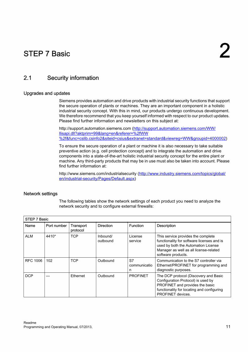
Network settingsThe following tables show the network settings of each product you need to analyze the network security and to configure external firewalls:
STEP 7 BasicName Port number Transport
protocolDirection Function Description
ALM 4410* TCP Inbound/outbound
License service
This service provides the complete functionality for software licenses and is used by both the Automation License Manager as well as all license-related software products.
RFC 1006 102 TCP Outbound S7 communication
Communication to the S7 controller via Ethernet/PROFINET for programming and diagnostic purposes.
DCP --- Ethernet Outbound PROFINET The DCP protocol (Discovery and Basic Configuration Protocol) is used by PROFINET and provides the basic functionality for locating and configuring PROFINET devices.
ReadmeProgramming and Operating Manual, 07/2013, 11
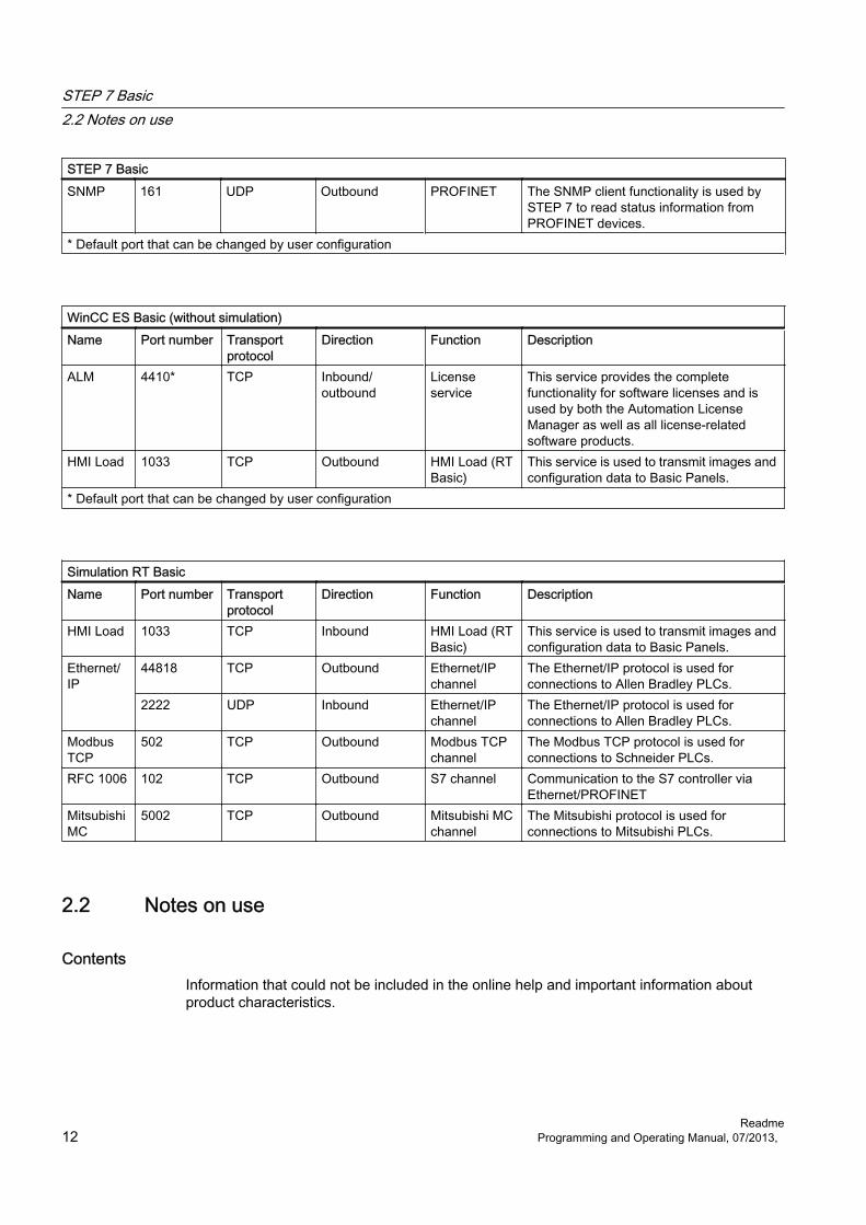
STEP 7 BasicSNMP 161 UDP Outbound PROFINET The SNMP client functionality is used by
STEP 7 to read status information from PROFINET devices.
* Default port that can be changed by user configuration
WinCC ES Basic (without simulation)Name Port number Transport
protocolDirection Function Description
ALM 4410* TCP Inbound/outbound
License service
This service provides the complete functionality for software licenses and is used by both the Automation License Manager as well as all license-related software products.
HMI Load 1033 TCP Outbound HMI Load (RT Basic)
This service is used to transmit images and configuration data to Basic Panels.
* Default port that can be changed by user configuration
Simulation RT BasicName Port number Transport
protocolDirection Function Description
HMI Load 1033 TCP Inbound HMI Load (RT Basic)
This service is used to transmit images and configuration data to Basic Panels.
Ethernet/IP
44818 TCP Outbound Ethernet/IP channel
The Ethernet/IP protocol is used for connections to Allen Bradley PLCs.
2222 UDP Inbound Ethernet/IP channel
The Ethernet/IP protocol is used for connections to Allen Bradley PLCs.
Modbus TCP
502 TCP Outbound Modbus TCP channel
The Modbus TCP protocol is used for connections to Schneider PLCs.
RFC 1006 102 TCP Outbound S7 channel Communication to the S7 controller via Ethernet/PROFINET
Mitsubishi MC
5002 TCP Outbound Mitsubishi MC channel
The Mitsubishi protocol is used for connections to Mitsubishi PLCs.
2.2 Notes on use
ContentsInformation that could not be included in the online help and important information about product characteristics.
STEP 7 Basic2.2 Notes on use
Readme12 Programming and Operating Manual, 07/2013,

Online operationThe simultaneous online operation of STEP 7 V5.5 or earlier and STEP 7 Basic V12 has not been approved.
Simultaneous online connections on an S7-1200 CPUIt is not possible to establish an online connection from multiple TIA Portal instances simultaneously to the same S7-1200 CPU.
Configuring and assigning module parametersYou will find an overview of the modules that can be configured and assigned parameters with STEP 7 Basic V12 at http://support.automation.siemens.com (http://support.automation.siemens.com/WW/view/en/28919804/133000).
Removing/inserting the memory cardAfter removing or inserting a memory card, always perform a memory reset on the CPU in order to restore the CPU to a functional condition.
Removing and inserting Ethernet modulesIf Ethernet modules are removed and re-inserted during operation, you must boot the PC; otherwise, the "Accessible devices" functionality in STEP 7 or NCM PC will not display all devices. While the PC boots, Ethernet modules must be activated.
Notes on the information systemThe following function has already been described in the information system, but is not available in STEP 7 Basic V12 SP1:
● Loading hardware configurations from the target system to the PG/PC.
Comparing project dataThe comparison functions (online/offline, offline/offline) currently do not take hardware into consideration.
Loading project data with TIA Portal V11 and V12 (S7-1200) If you load the project data of an S7-1200 CPU with the TIA Portal V12, you can no longer use TIA Portal V11 to access this data. To do this, first restore the factory settings of the CPU. Read the additional information on this in the online help under "How to reset a CPU to factory settings".
STEP 7 Basic2.2 Notes on use
ReadmeProgramming and Operating Manual, 07/2013, 13

Activating ENO enable outputAs of STEP 7 TIA Portal V12.0, the ENO enable output is disabled by default in the programming languages LAD and FBD and the ENO parameter is shown grayed out. If needed, you can activate the enable output and thereby specifically control the instructions for which you want to have error evaluation.
To activate the ENO enable output of an instruction, follow these steps:
1. In your program, right-click the instruction for which you want to activate the ENO enable output.
2. Select the "Generate ENO" command from the shortcut menu.The ENO value is generated for the instruction and the color of the ENO parameter changes from gray to black.Additional instructions are inserted with the enable output.
CompatibilityThe device configuration and program of an S7-1200 CPU must always be configured with the same STEP 7 version. Usually, the TIA Portal makes sure that no version conflicts occur by outputting appropriate notifications during loading to the device.
This automatic verification is not possible with S7-1200 CPUs with firmware version V1.x. In this case, users themselves must ensure that no version conflicts occur.
2.3 Editing devices and networks
2.3.1 General information on devices and networks
Contents Currently, there is no general information available on devices and networks.
2.3.2 Use of modules on the S7-1200
ContentsInformation that could not be included in the online help and important information about product characteristics.
STEP 7 Basic2.3 Editing devices and networks
Readme14 Programming and Operating Manual, 07/2013,

Use of modules on the S7-1200The modules listed below are not supported on the S7-1200.
Family Module Order numberS7-300 FMs SM 338 6ES7 338-4BC01-0AB0
FM 350-1 6ES7 350-1AH03-0AE0FM 350-2 6ES7 350-2AH00-0AE0, 6ES7 350-2AH01-0AE0FM 351 6ES7 351-1AH01-0AE0, 6ES7 351-1AH02-0AE0FM 352 6ES7 352-1AH02-0AE0FM 355 S 6ES7 355-1VH10-0AE0FM 355 C 6ES7 355-0VH10-0AE0FM 355-2 C 6ES7 355-2CH00-0AE0FM 355-2 S 6ES7 355-2SH00-0AE0
S7-300 PtP-CP CP 340 6ES7 340-1AH02-0AE0, 6ES7 340-1BH02-0AE0, 6ES7 340-1CH02-0AE0
CP 341 6ES7 341-1AH01-0AE0, 6ES7 341-1AH02-0AE0, 6ES7 341-1BH01-0AE0, 6ES7 341-1BH02-0AE0, 6ES7 341-1CH01-0AE0, 6ES7 341-1CH02-0AE0
Network component Diagnostics repeater 6ES7 972-0AB01-0XA0ET 200S 1 Count 24 V 6ES7 138-4DA04-0AB0
1 Count 5 V 6ES7 138-4DE02-0AB01 Step 5 V 6ES7 138-4DC00-0AB0, 6ES7 138-4DC01-0AB02 pulses 6ES7 138-4DD00-0AB0, 6ES7 138-4DD01-0AB01 SI 6ES7 138-4DF01-0AB01 SI Modbus 6ES7 138-4DF11-0AB01 SSI 6ES7 138-4DB02-0AB0, 6ES7 138-4DB03-0AB01 Pos Universal 6ES7 138-4DL00-0AB0SIWAREX 7MH4910-0AA01, 7MH4912-0AA01, 7MH4920-0AA01
ET 200M SIWAREX 7MH4 900-2AA01, 7MH4 900-3AA01, 7MH4 950-1AA01, 7MH4 950-2AA01
2.3.3 Replacing ET 200S positioning modules
ContentsInformation that could not be included in the online help and important information about product characteristics.
Replacing ET 200S positioning modulesThis information relates to the positioning module "1 Step 5V" (6ES7 138-4DC00-0AB0) from a project which was created with TIA Portal V11.0. When replacing these modules from the TIA Portal V11.0 with a new version of these modules, the parameter settings are reset to the default values.
STEP 7 Basic2.3 Editing devices and networks
ReadmeProgramming and Operating Manual, 07/2013, 15

This is the case with one of the following procedures:
● Replace the positioning module 6ES7 138-4DC00-0AB0 with its successor module 6ES7 138-4DC01-0AB0 by means of a device exchange.
● Updating the module version using the appropriate button in the device properties in the Inspector window.
2.3.4 CP 343-2 on SIMATIC S7 Embedded Controller EC31-RTX
ContentsInformation that could not be included in the online help and important information about product characteristics.
CP 343-2 on SIMATIC S7 Embedded Controller EC31-RTXThe module AS-Interface CP 343-2 (order no.: 6GK7 343-2AH01) can be inserted in an expansion rack of the SIMATIC S7 Embedded Controller EC31-RTX (order no.: 6ES7 677-1DDxx-0BB0), but the CP 343-2 cannot be operated with the EC31-RTX.
2.3.5 Notes on online and diagnostics
ContentsInformation that could not be included in the online help and important information about product characteristics.
Hardware detection followed by online connectionWhen the "Online > Hardware detection" command is performed for an unspecified CPU, the online configuration is not loaded from the CPU. If you do not load the configuration resulting from the hardware detection to the CPU, the device and network views will always show a difference between the offline and online configurations. It will appear that there are different configurations in the online and diagnostic views, although the MLFBs are identical in the actual CPU and the offline CPU.
STEP 7 Basic2.3 Editing devices and networks
Readme16 Programming and Operating Manual, 07/2013,

2.3.6 Network components
2.3.6.1 Network components
CP 1242-7
Copying the CP 1242-7 into another projectIf you copy a CP 1242-7 from one project into another project, the following parameters in the parameter group "CP identification" are changed on the target station:
● Project number of the CP
● Station number of the CP
Download to deviceOnly use the "Download to device" function with the CP 1242‑7 via a TeleService connection as follows:
1. Select the CP in STEP 7.
2. Select the "Online" > "Download to device" menu.
3. In the "Extended download" dialog that appears, select the TeleService interface.
4. Download the project data from the "Extended download" dialog.
Upload from deviceThe function "Upload from device" is not supported by the CP 1242‑7.
SCALANCE X
SCALANCE XR500 as IO device: "Compile" and "Download to device"With a SCALANCE XR500 configured as a PROFINET IO device and assigned to an IO controller, the functions "Compile" and "Download to device" only download the data to the switch that can also be configured in Web Based Management (WBM) (layer 2, layer 3, system, security).
If you want to use the "Compile" or "Download to device" functions for the PROFINET IO device data of the XR500, first select the assigned IO controller.
STEP 7 Basic2.3 Editing devices and networks
ReadmeProgramming and Operating Manual, 07/2013, 17

Using a link aggregation in an MSTP instanceIf you want to use a link aggregation in an MSTP instance, follow the steps below during configuration:
1. Create a link aggregation in "Layer 2" > "Link Aggregation".
2. Create an MSTP instance in in "Layer 2" > "MSTP" > "MST General".
3. Configure the link aggregation in "Layer 2" > "MSTP" > "MST Port".
Automatic activation of MRP in redundant topologiesIf you connect SCALANCE X switches with redundant network structures in the topology view, MRP is activated automatically on the switches involved.
If there is an existing configuration with other redundancy mechanisms, such as MSTP, this is automatically deactivated.
2.4 Programming a PLC
2.4.1 General notes on PLC programming
ContentsInformation that could not be included in the online help and important information about product characteristics.
Loading inconsistent programs to a deviceIn TIA Portal, it is not possible to download inconsistent programs to a device without a consistency check. During the loading process, all blocks of the program are implicitly checked and are compiled again in the event of inconsistencies. If, however, there are programs on your CPU which were loaded with earlier versions of STEP 7, these programs could demonstrate inconsistencies.
In this case, note the following:
If you load an inconsistent program from a device, you will not be able to load the program unchanged to the device afterwards, because a consistency check always takes place during the loading process and existing inconsistencies are corrected.
Process image of PTO/PWM outputsDo not use PTO/PWM outputs in the process image (for example, for access in the user program, for online functions or in HMI). The update rate of the process image is much slower than the rate of the signal changes. The display in the process image therefore does not reflect the signal flow.
STEP 7 Basic2.4 Programming a PLC
Readme18 Programming and Operating Manual, 07/2013,

Monitoring blocks in LAD and FBDIf the start of the current path is outside the visible range, it may not be possible to determine the input value. In this case, the current path is shown grayed out.
Avoid using PLC data types generated by the system in librariesSome instructions generate their own PLC data types during instancing which are saved in the "PLC data types" project folder. However, you should not use these system-generated PLC data types in any library, because they may be recreated by the system at any time and may result in an unfavorable system behavior.
Using global data blocks in assignmentsIt is not possible to assign the contents of a global data block to a structurally identical data block, e.g. using a move box.
Conversion of know-how protected blocks from V10.5The program must be compiled after conversion from previous STEP 7 versions (e.g., STEP 7 V10.5). If you are using know-how protected blocks, you are prompted to enter the password.
2.4.2 Instructions
ContentsInformation that could not be included in the online help and important information about product characteristics.
Use of instructions (S7-1200)If a parameter-specific error occurs with instructions which represent a system function (SFC) or system function block (SFB), no error code is output at parameter RET_VAL. RET_VAL is invalid in this case. You have a number of different options for responding to these errors, depending on the CPU used.
Instruction "TRCV_C: Receive data via Ethernet" Contrary to the information provided in the online help, the communication connection is terminated immediately, and not after sending data, when the CONT parameter is set to the value "0".
Instruction "T_CONFIG: Configure interface" The CPU is restarted after you have executed the "Configure interface" instruction in order to change an IP parameter. The CPU goes to STOP mode, a warm restart is carried out and the CPU starts up again (RUN mode). Make sure that the control process is in a secure operating
STEP 7 Basic2.4 Programming a PLC
ReadmeProgramming and Operating Manual, 07/2013, 19

mode after the CPU has been restarted following execution of the "Configure interface" instruction. Uncontrolled operation can result in serious material damage or personal injury due to malfunctions or programming errors, for example. Non-retentive data could be lost.
Parameters ERROR and STATUS
ERROR STATUS(DW#16#..)
ERR_LOC Explanation
0 00000000 0 After the instruction has been executed successfully, the STATUS parameter "00000000" does not return any value.
Instruction "GET_DIAG: Read diagnostics information"MODE 3 at the MODE parameter is not supported by the S7-1200 CPU.
Using instructions with parameters of type VARIANT in code blocks with different access types (S7-1200)
Code blocks (FBs/FCs) and data blocks (DBs) can be created with different access types ("standard" and "optimized"). In code blocks, you can call any instructions. Certain instructions (for example, "WRIT_DBL" and "READ_DBL") use pointers of type VARIANT at input and output parameters to address data blocks.
Ensure that you do not use these instructions in programs in which code blocks of different access types are called reciprocally. This could cause the following to occur:
● A structure from a standard data block is directly or indirectly passed to an optimized code block, which forwards this structure directly or indirectly to one of the blocks mentioned above.
● The reverse scenario, whereby a structure from an optimized code block is directly or indirectly passed to a standard data block, which forwards this structure directly or indirectly to one of the blocks mentioned above.
2.4.3 Testing the user program
2.4.3.1 Testing with the watch table
ContentsInformation that could not be included in the online help and important information about product characteristics.
STEP 7 Basic2.4 Programming a PLC
Readme20 Programming and Operating Manual, 07/2013,

Multiple access to the same CPUAccess to a CPU from a PG/PC is permitted only when a TIA Portal is open. Multiple access to the same CPU is not permitted and can lead to errors.
Loading data blocks during an active control job
Note
Loading changed data blocks during an active control job can result in unforeseen operating states. The control job continues to control the specified address, although the address allocation may have changed in the data block. Complete active control jobs before loading data blocks.
Testing programs converted from STEP 7 V10.5.To monitor and test a program converted from STEP 7 V10.5, you have to first compile and load with STEP 7 V11.0.
"Enable peripheral outputs" functionIn TIA Portal V12.0, the function "Enable peripheral outputs" is not available for CPUs from the S7-1500 series.This function can only be carried out with an S7-300, S7-400 or S7-1200 CPU in TIA Portal V12.0.
2.4.3.2 Testing with the force table
ContentsInformation that could not be included in the online help and important information about product characteristics.
Forcing tags for direct I/O accessIf you use direct I/O access for an S7-300 CPU in your user program, forcing this I/O address is not permitted.
ExampleIf I/O access to the address "IB0:P" takes place in the user program, it is not permitted to force the following I/O address areas: I0.0:P, IB0:P, IW0:P and ID0:P.
STEP 7 Basic2.4 Programming a PLC
ReadmeProgramming and Operating Manual, 07/2013, 21

2.5 Technological functions
2.5.1 Notes on technological functionsThere are no notes about the technology functions.
STEP 7 Basic2.5 Technological functions
Readme22 Programming and Operating Manual, 07/2013,

WinCC Professional 33.1 Security information
Security informationSiemens provides automation and drive products with industrial security functions that support the secure operation of plants or machines. They are an important component in a holistic industrial security concept. With this in mind, our products undergo continuous development. We therefore recommend that you keep yourself informed about our product updates. You can find additional information and newsletters on this subject at:
http://support.automation.siemens.com (http://support.automation.siemens.com)
To ensure the secure operation of a plant or machine, it is also necessary to implement appropriate preventive measures (e.g. cell protection concept) and to integrate the automation and drive components into a comprehensive, state-of-the-art industrial security concept for the entire plant or machine. Products used from other manufacturers should also be taken into account here. You can find additional information at:
http://www.siemens.com/industrialsecurity. (http://www.industry.siemens.com/topics/global/en/industrial-security/Pages/Default.aspx)
PasswordsVarious passwords are set by default in WinCC. For security reasons, you should change these passwords.
● The default password for the Sm@rtServer and for the integrated Web server is "100".
● For the user "Administrator", the default password is "administrator".
Integrated Web serverIt is always possible on a PC to access HTML pages in Runtime, even though the option"HTML pages" is disabled. Setup always installs the standard pages of the Web Server on the PC. Assign an administrator password to prevent unauthorized access to the pages.
Communication via EthernetIn Ethernet-based communication, end users themselves are responsible for the security of their data network. The proper functioning of the device cannot be guaranteed in all circumstances; targeted attacks, for example, can lead to overload of the device.
Closing Runtime automaticallyIf automatic transfer is enabled on the HMI device and a transfer is started on the configuration PC, the running project is automatically stopped.
ReadmeProgramming and Operating Manual, 07/2013, 23
The HMI device then switches autonomously to "Transfer" mode.
After the commissioning phase, disable the automatic transfer function to prevent the HMI device from switching inadvertently to transfer mode.
Transfer mode can cause undesired reactions in the system.
To block access to the transfer settings and thus avoid unauthorized changes, assign a password in the Control Panel.
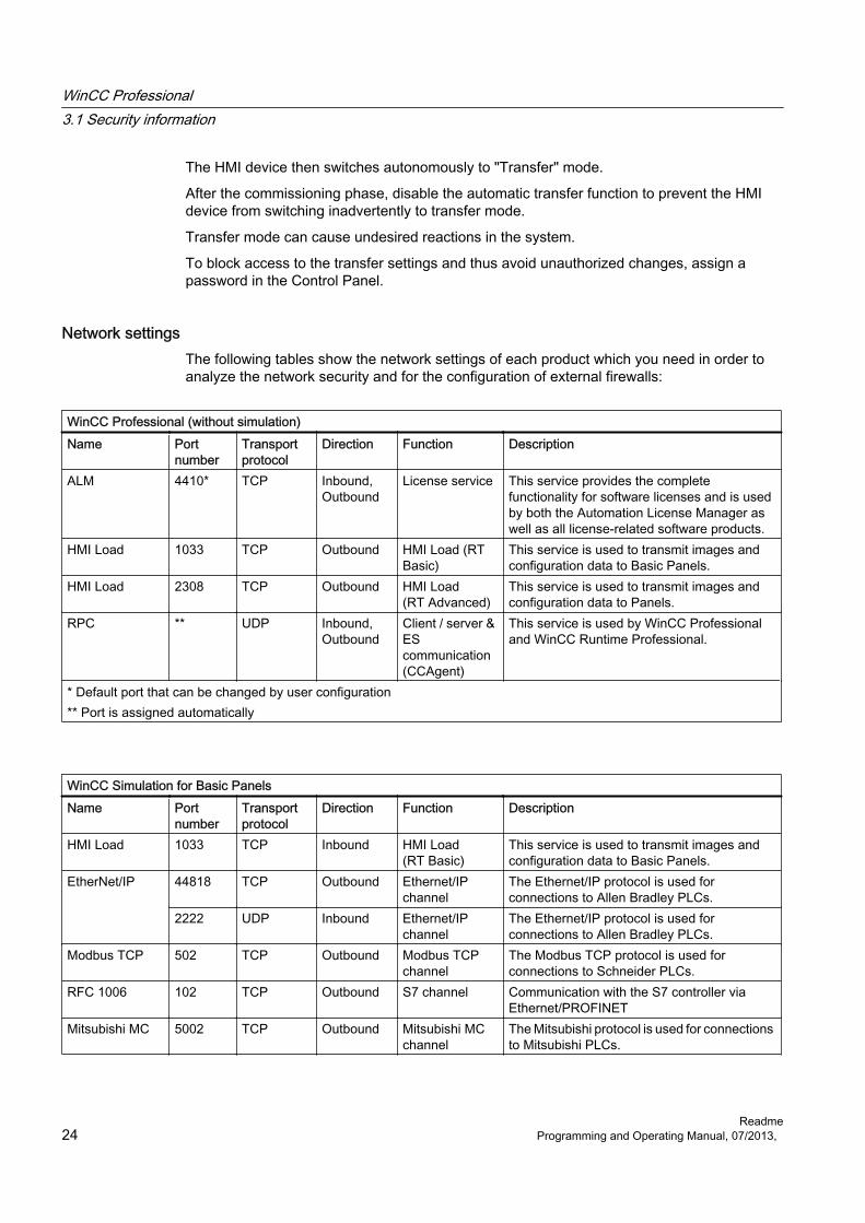
Network settingsThe following tables show the network settings of each product which you need in order to analyze the network security and for the configuration of external firewalls:
WinCC Professional (without simulation)Name Port
numberTransport protocol
Direction Function Description
ALM 4410* TCP Inbound, Outbound
License service This service provides the complete functionality for software licenses and is used by both the Automation License Manager as well as all license-related software products.
HMI Load 1033 TCP Outbound HMI Load (RT Basic)
This service is used to transmit images and configuration data to Basic Panels.
HMI Load 2308 TCP Outbound HMI Load (RT Advanced)
This service is used to transmit images and configuration data to Panels.
RPC ** UDP Inbound, Outbound
Client / server & ES communication (CCAgent)
This service is used by WinCC Professional and WinCC Runtime Professional.
* Default port that can be changed by user configuration** Port is assigned automatically
WinCC Simulation for Basic PanelsName Port
numberTransport protocol
Direction Function Description
HMI Load 1033 TCP Inbound HMI Load (RT Basic)
This service is used to transmit images and configuration data to Basic Panels.
EtherNet/IP 44818 TCP Outbound Ethernet/IP channel
The Ethernet/IP protocol is used for connections to Allen Bradley PLCs.
2222 UDP Inbound Ethernet/IP channel
The Ethernet/IP protocol is used for connections to Allen Bradley PLCs.
Modbus TCP 502 TCP Outbound Modbus TCP channel
The Modbus TCP protocol is used for connections to Schneider PLCs.
RFC 1006 102 TCP Outbound S7 channel Communication with the S7 controller via Ethernet/PROFINET
Mitsubishi MC 5002 TCP Outbound Mitsubishi MC channel
The Mitsubishi protocol is used for connections to Mitsubishi PLCs.
WinCC Professional3.1 Security information
Readme24 Programming and Operating Manual, 07/2013,
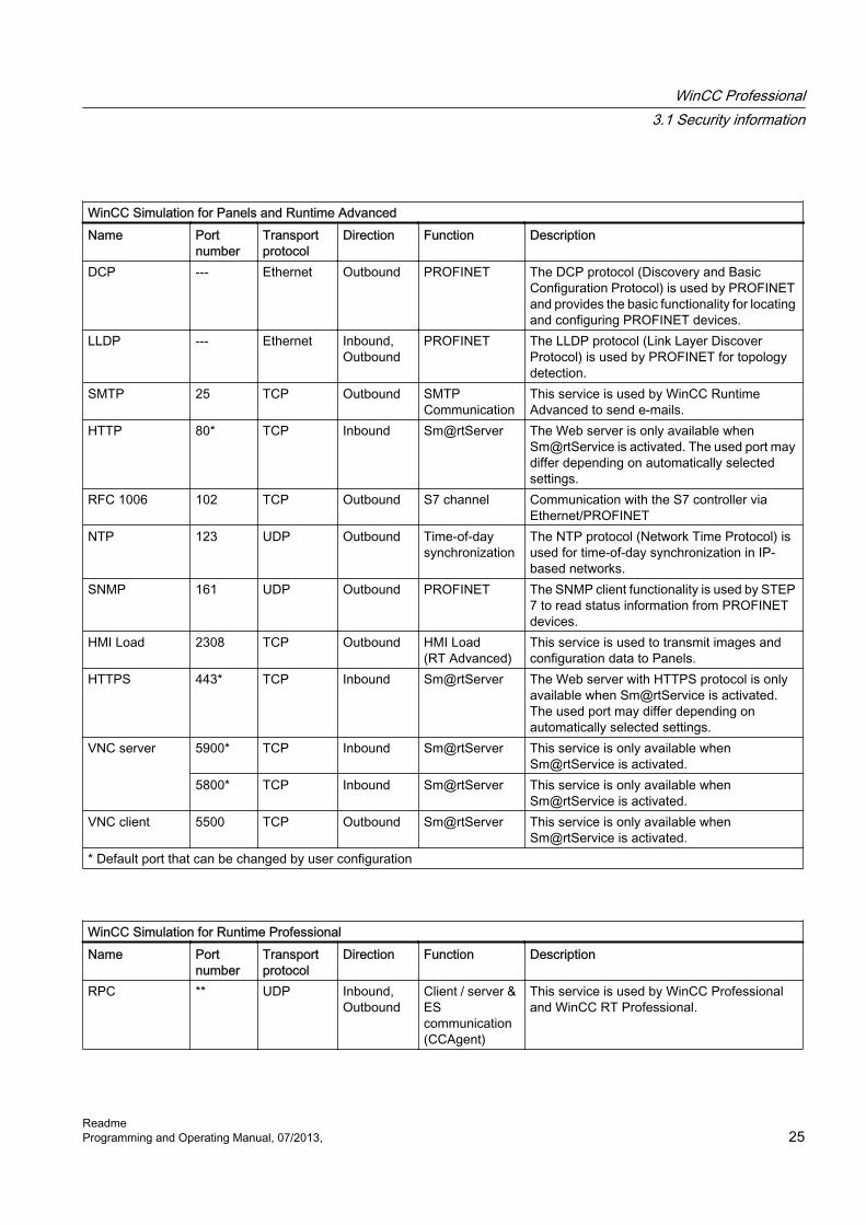
WinCC Simulation for Panels and Runtime AdvancedName Port
numberTransport protocol
Direction Function Description
DCP --- Ethernet Outbound PROFINET The DCP protocol (Discovery and Basic Configuration Protocol) is used by PROFINET and provides the basic functionality for locating and configuring PROFINET devices.
LLDP --- Ethernet Inbound, Outbound
PROFINET The LLDP protocol (Link Layer Discover Protocol) is used by PROFINET for topology detection.
SMTP 25 TCP Outbound SMTP Communication
This service is used by WinCC Runtime Advanced to send e-mails.
HTTP 80* TCP Inbound Sm@rtServer The Web server is only available when Sm@rtService is activated. The used port may differ depending on automatically selected settings.
RFC 1006 102 TCP Outbound S7 channel Communication with the S7 controller via Ethernet/PROFINET
NTP 123 UDP Outbound Time-of-day synchronization
The NTP protocol (Network Time Protocol) is used for time-of-day synchronization in IP-based networks.
SNMP 161 UDP Outbound PROFINET The SNMP client functionality is used by STEP 7 to read status information from PROFINET devices.
HMI Load 2308 TCP Outbound HMI Load (RT Advanced)
This service is used to transmit images and configuration data to Panels.
HTTPS 443* TCP Inbound Sm@rtServer The Web server with HTTPS protocol is only available when Sm@rtService is activated. The used port may differ depending on automatically selected settings.
VNC server 5900* TCP Inbound Sm@rtServer This service is only available when Sm@rtService is activated.
5800* TCP Inbound Sm@rtServer This service is only available when Sm@rtService is activated.
VNC client 5500 TCP Outbound Sm@rtServer This service is only available when Sm@rtService is activated.
* Default port that can be changed by user configuration
WinCC Simulation for Runtime ProfessionalName Port
numberTransport protocol
Direction Function Description
RPC ** UDP Inbound, Outbound
Client / server & ES communication (CCAgent)
This service is used by WinCC Professional and WinCC RT Professional.
WinCC Professional3.1 Security information
ReadmeProgramming and Operating Manual, 07/2013, 25

WinCC Simulation for Runtime ProfessionalRPC ** UDP Inbound,
OutboundClient / server communication (CCEServer / CCEClient)
This service is used by WinCC Runtime Professional.
HTTP 80 TCP Inbound, Outbound
Client / server communication (CCEServer / CCEClient)
This service is used by WinCC Runtime Professional.
RFC 1006 102 TCP Outbound S7 channel Communication with the S7 controller via Ethernet/PROFINET
OPC UA 4840 TCP Inbound OPC UA server This service is required for primary communication via OPC UA. It is activated and configured during installation.
OPC UA discovery
52601 TCP Inbound OPC UA server The OPC UA discovery service provides information about installed OPC servers on the same system. This one will be active if installed and configured via the OPC UA server.
DCOM 135 TCP Inbound OPC server This service is part of the Windows operating system. DCOM functionality is part of Microsoft Windows operating system. Because communication via OPC (DA) is based on DCOM, this service is required to initialize OPC (DA) connections.
DCOM ** TCP Inbound OPC server The communication via OPC (DA) is based on DCOM and uses unspecified ports assigned by the system. This should be taken into consideration when using OPC (DA) and creating rules for the firewall.
HTTP 80 TCP Inbound OPC server This service is required for primary communication via OPC XML. It is activated and configured during installation.
NetBIOS 137 UDP Inbound OPC server This service is part of the Windows operating system. Access to this service is required by OPC-Scout, for example, for browsing.
NetBIOS 138 UDP Inbound OPC server This service is part of the Windows operating system. Access to this service is required by OPC-Scout, for example, for browsing.
SNMP 161 UDP Outbound SNMP OPC server
This service is used by the SNMP OPC server to change or query data on network drives, for example.
SNMP Traps 162 UDP Inbound SNMP OPC server
This service is used by the SNMP OPC server to query events from network drives, for example.
** Port is assigned automatically
WinCC Professional3.1 Security information
Readme26 Programming and Operating Manual, 07/2013,

3.2 Notes on use
ContentsInformation that could not be included in the online help and important information about product characteristics.
Installation on a computer with regional setting "Turkish"If the computer is operated with the regional setting "Turkish" at the time of the installation, WinCC Runtime Professional cannot be started.
Copying HMI devices with HMI connectionsIf you copy an HMI device with HMI connections to a PLC, the HMI connection in the new HMI device is not automatically connected to an existing PLC with the same name. This applies to copying within a project as well as copying across projects.
To access the PLC tag via HMI tag in the new HMI device, you have to complete the HMI configuration immediately after copying. Proceed as follows:
1. Open the "Devices & Networks" editor.
2. Connect the new HMI device to the desired network.
3. Open the connection table.
4. Select the HMI connection of the new HMI device.
5. Select the desired PLC under "Partner".
If you compile the new HMI device or connect additional PLC tags in between copying the HMI device and completing the connection, there may be some instances in which an additional HMI connection to the same PLC is created. This is especially true if you connect HMI tags with DB array elements.
Device replacementAfter an HMI device has been replaced, you should check the appearance of the configured screens. Changing the size of the display may result in changes to the position and appearance of screen objects, e.g. recipe view and alarm view.
Device replacement - character setsIf you have configured different character sets on screen objects for multilingual texts in the various project languages, you should check the screens after an HMI device replacement from a panel to a PC-based Runtime. The configured character sets may be changed by the device replacement.
Device replacement - communicationIf an HMI device is replaced, error messages of the type "... is not supported in the new configuration and will therefore be removed" may be generated. These alarms refer to
WinCC Professional3.2 Notes on use
ReadmeProgramming and Operating Manual, 07/2013, 27

configured connections of the device and are triggered, for example, if the HMI devices have a different number of interfaces. These connections are marked red after a device replacement. If you would like to continue to use these connections, you have change the configuration of the connection. Proceed as follows:
1. Open the "Devices and Networks" editor.
2. Click "Network" in the toolbar of the network view.
3. Network the interface of the HMI device with the interface of the CPU.
4. Click in the table area of the network view on the "Connections" table.
5. Select the connection marked red.
6. Enter the new interface under "Properties > General > Interface" in the Inspector window.
Specifying the time of modification in the overview windowThe times of modification displayed in the overview window only refer to changes to the object itself. Changes to subordinate objects, e.g. screen objects in a screen, do not cause the time of the last change to the screen to change in the overview window.
HMI device wizardWhen you create a device with a color display using the HMI device wizard, the graphics of the navigation buttons may be displayed in black and white. This error only occurs, however, if the new device is created with the same name as a device with a monochrome display which has been deleted in the meantime.
You can avoid this error by always deleting the associated graphics in the Graphics collection whenever you delete a device from the project.
Objects with object references in the project libraryTwo copying methods can be used in WinCC flexible.
● With "simple copy" a WinCC flexible screen including an IO field, for example is copied. Only the object name of a tag configured on the IO field is copied, as this is a reference.
● With "copy", a screen, an IO field contained there and a tag configured on the IO field together with its properties are copied.
These two methods can also be used for storing an object in a library. Project libraries and the objects contained there are migrated during migration and can be used in WinCC.
In WinCC, however, only one copying method is available. With regard to tags, it functions like "simple copy" in WinCC flexible. With regard to graphics, graphics lists and text lists, it functions like "copy" in WinCC flexible.
If you stored objects with references to tags in a library in WinCC flexible, you must reconfigure the referenced objects when using them in WinCC.
WinCC Professional3.2 Notes on use
Readme28 Programming and Operating Manual, 07/2013,

WinCC Professional 3.2 Notes on use
Readme
Programming and Operating Manual, 12/2007 29
Reports with Asian character sets on Windows CE devices If Asian characters sets are displayed in an illegible manner in a report on a Windows CE device, you must change the character sets for the objects in the report. it is sufficient to change to a different character set and then reset the original character set.
Saving the WinCC project If you save a project in WinCC using the "Save As…" command, this has no effect on the names of the Runtime projects generated for Runtime Professional. If you do not adapt the destination path of the devices in the "Extended download to device" dialog, the Runtime projects on the target devices will be overwritten. Configuration changes from the original project and configuration changes from the newly saved project may influence each other.
Therefore, change the destination path of the devices in the "Extended download to device" dialog.
Texts in the simulation If a Runtime language which does not correspond to an installed product language is used in the simulation, system texts are shown in an installed product language. Depending on the operating system and the installed product languages, this will be either English or Chinese.
If you wish to see all texts in Japanese, Korean or Taiwanese in the relevant language in the simulation, you should first install WinCC without simulation. Then install WinCC Runtime Professional with the required languages.
Invalid Runtime language You may only select the Runtime languages for WinCC Professional that are compatible with the current settings on your PC. The setting is available in the Control Panel, "Regional and Language Options > Advanced > Languages for non-Unicode programs" dialog.
The default font is marked as invalid if you select an incompatible Runtime language in the "Runtime settings > Languages & font" editor.
Security settings in the Security Controller You can find the "Securitiy Controller" in the start menu under "Start > Programs > Siemens Automation". You can display and print security settings using the program.
However, do not use "Edit > Make settings" and/or the function "Make setting" in the menu.
Online delta load with user-defined cyclesIf you have configured new custom cycles in the "Cycles" editor, "Load > Software (compile all)" command when loading the project. Delta loading is not possible in online mode.
License transfer via S7USBYou always need to run WinCC to transfer a license to a panel via S7USB.
Transferring licenses to a panel on 64-bit operating systemsIf you are running a 64-bit operating system and the "Edit > Connect target systems > Connect HMI device" menu command is not available in Automation License Manager, open command line input and run the following command with administrator rights:
"%WINDIR%\system32\RegSvr32.exe" "%CommonProgramFiles%\siemens\AlmPanelPlugin\ALMPanelParam.dll"
Installation sequence for StartdriveWhen you install Startdrive on a PC, adhere to the following installation sequence:
● Install STEP7 V12.0.
● Install Startdrive.
SIMOTIONSIMOTION is not supported with WinCC V12 SP1.
Security settings during installationWhen you install WinCC V12, security settings are changed in your operating system.
The security settings in question are listed during the installation.
You must confirm the changes to the security settings.
If you make changes to your operating system after the installation, the changes to the security settings made by the installation of the TIA Portal could be changed.
You can restore the changes to the security settings made by the installation of the TIA Portal:
"Start > All Programs > Siemens Automation > Security Controller > Restore settings"
SQL instance of WinCC V12If you have installed a WinCC V11 product and you wish to install a WinCC V12 product, you must uninstall all WinCC V11 products and the WinCC instance of SQL Server 2005 one after the other before the installation.
A new WinCC SQL 2008 instance is installed with the installation of WinCC V12.
WinCC Professional3.2 Notes on use
Readme30 Programming and Operating Manual, 07/2013,

3.3 Migration
ContentsInformation that could not be included in the online help and important information about product features.
Changing the names of alarm classesIn contrast to WinCC flexible, the names of the predefined alarm classes are not dependent on the user interface language currently in use. During migration, the names of the alarm classes are assigned as follows:
WinCC flexible WinCCError ErrorsSystem SystemWarnings Warnings
The display names of the alarm classes can be changed as necessary after migration.
Project languages in WinCCWinCC V12 does not support all project languages that were available in WinCC flexible, such as Arabic. If you receive an empty project as the result of your migration, you may want to check the set editing language. Do not set the project languages that are not supported as editing language in the source project. Proceed as follows:
1. Open the project with WinCC flexible.
2. Change the editing language to English, for example.
3. Save the project.
4. Restart the migration.
Objects with object references in the project libraryTwo copying methods can be used in WinCC flexible.
● With "simple copy", a WinCC flexible screen including an IO field, for example, is copied. Only the object name of a tag configured on the IO field is copied, as this is a reference.
● With "copy", a screen, an IO field contained there and a tag configured on the IO field together with its properties are copied.
These two methods can also be used for storing an object in a library. Project libraries and the objects contained there are migrated during migration and can be used in WinCC.
In WinCC, however, only one copying method is available. It functions like "simple copy" in WinCC flexible.
If you have stored objects with references to other objects in a library in WinCC flexible, you must reconfigure the referenced objects when using them in WinCC.
WinCC Professional3.3 Migration
ReadmeProgramming and Operating Manual, 07/2013, 31

Migrating an integrated project with ProTool objectsThe "PROTOOL option package(s) missing in STEP 7" error message output during migration of a WinCC flexible project that is integrated in STEP 7 indicates that WinCC flexible 2008 SP3 is installed on your system. Moreover, the project still contains objects that were configured using ProTool. Do not open the project with WinCC flexible 2008 SP3! Proceed as follows to migrate the project:
1. Copy the project to a computer on which WinCC flexible 2008 SP2 and STEP 7 are installed.
2. Open the project in the SIMATIC Manager.
3. Remove all ProTool objects from the project.
4. Execute the "Save as" command in the "File" menu.
5. Activate the option "With reorganization" in the "Save project as" dialog.
6. Click OK.
7. Copy the project back to the original computer.
8. Restart the migration.
Migrating a WinCC V7 project with "Chinese (Taiwan)" Runtime languageIf your WinCC is installed with support for the "Chinese" user interface language, the texts and report layouts of the "Chinese (Taiwan)" Runtime language will not be included when you migrate WinCC V7 projects. Migrate such projects using the Migration Tool, or a PC that contains a WinCC setup without "Chinese" user interface language.
Progress barAs long as the progress bar still shows a value of 100 %, the software is still busy running remaining tasks such as the closing of references. The software will not respond to user input while this status is given.
PrincipleWhen you open a V11 project with a V12 version, it will no longer be possible to open this project with an older version afterwards.
Managing third-party ActiveX controlsThe migration also supports third-party ActiveX controls. However, the controls must be registered in the operating system. If an ActiveX control is not registered, migration is canceled.
If you save a project with the migration tool and perform the migration yourself on another PC, the controls must also be registered on this PC.
Language switching in RTUpgrading the project from V11 to V12 and migration of WinCC V7.0 SP3 to V12:
WinCC Professional3.3 Migration
Readme32 Programming and Operating Manual, 07/2013,
If you have used a script to program a language change to Chinese (PRC) in V11 or V7.0 SP3 with LCID, language switching to Chinese (PRC) in runtime no longer works after upgrading or migrating.
Change the LCID in script from "1028" to "2052".
Migrating integrated projects with alarm views An alarm view is enabled with all alarm classes in an integrated project. The alarm classes are disabled during migration of the project.Once the migration of the project is completed, check the settings in the alarm view. Enable the require alarm classes in the Inspector window of the alarm view if needed under "Properties > General".
Migrating projects from WinCC V7We recommend a 64-bit operating system for the migration of extensive projects from WinCC V7.0 SP3.
See alsoObject support during migration
3.4 Special considerations for Windows 7
Contents Information that could not be included in the online help and important information about product characteristics.
Permission for the starting RuntimeTo start WinCC Runtime Professional or WinCC Runtime Advanced, a user must be a member of the automatically created group, "Siemens TIA Engineer".
Working with standard user rights If you are working with standard user rights in Windows 7, "User Account Control (UAC)" cannot be disabled.
The "User Account Control" is enabled in Windows 7 by default.
For more information on the "User Account Control, refer to the online help for Windows 7.
WinCC Professional3.4 Special considerations for Windows 7
ReadmeProgramming and Operating Manual, 07/2013, 33

Slow response from the screen keyboard and SmartServerThe following programs may start and respond very slowly under Windows 7 and Windows 2008 servers:
● Microsoft OSK screen keyboard and HMI TouchInputPC
● SmartServer: <Ctrl+Alt+Del> shortcut in the logon dialog
The delay is caused by the callback for the Internet certificate validation.
Remedy:
You can find the following fileson the product DVD under:Support\Windows7\CRL_Check or CD_RT\ Support\Windows7\CRL_Check\:
● DisableCRLCheck_LocalSystem.cmd
● DisableCRLCheck_CurrentUser.cmd
1. Run the "DisableCRLCheck_LocalSystem.cmd" file with administrator rights. Select the command "Run as administrator" from the shortcut menu of the file.
2. Reboot the PC.
If the problem persists, follow these steps:
1. Double-click the file and run the "DisableCRLCheck_CurrentUser.cmd" file with user rights.
2. Reboot the PC.
Note
The callback for the certificate validation is disabled for all users or PCs. To restore the original state, perform the following files:● RestoreDefaults_LocalSystem.cmd● RestoreDefaults_CurrentUser.cmd
You can find the files in the following directory of product DVD:● Support\Windows7\CRL_Check or CD_RT\Support\Windows7\CRL_Check\
On-screen keyboardOnce you have opened the TIA Portal, you can no longer call the on-screen keyboard.
To call the on-screen keyboard in Windows, use the following command: "Start > All Programs > Accessories > Ease of access > On-screen keyboard".
WinCC Professional3.4 Special considerations for Windows 7
Readme34 Programming and Operating Manual, 07/2013,
3.5 Engineering System
3.5.1 Screens and Screen Objects
ContentsInformation that could not be included in the online help and important information about product features.
Text format of output fields in alarm textIt is not possible to underline tags and text list entries.
Copying display objects between two projects or two devicesIn Project_1 configure an alarm window in the Global Screen, for example. You copy the alarm window and paste it in the Global Screen in Project_2.
The enabled alarm classes are partly not enabled in the alarm window after pasting.
This behavior applies to the following display objects:
● Alarm window
● Alarm indicator
● Alarm view
Representation of the cross-references in the Inspector windowThe Inspector window displays objects used by a screen object in the "About > Cross-reference" tab.
A screen is open and an object selected. You are using an HMI tag at the object as process tag.
The object and the linked HMI tag are displayed in the cross-references. All locations of use of the object and the HMI tags are listed.
If the HMI tag is interconnected with a PLC tag or a DB tag, then the locations of use of the interconnected PLC tag or DB tag will be displayed.
Event names in case of alarms in the "Info" tab of the Inspector windowIn some alarms of the Inspector window the event names in the "Info" tab will deviate from the names in the "Properties" tab.
WinCC Professional3.5 Engineering System
ReadmeProgramming and Operating Manual, 07/2013, 35

Name in the "Properties" tab of the Inspector window
Name in the "Info" tab of the Inspector window
Cleared ClearScreenLoaded GenerateScreenEnable ActivateChange ChangeWhen a dialog is opened ONMODALBEGINWhen a dialog is closed ONMODALENDUser change PASSWORDScreen change SCREENDisable DeactivatePress PressOutgoing GoingIncoming ComingLimit "high limit error" violated AboveUpperLimitLimit "low limit error" violated BelowLowerLimitClick ClickLoop-In-Alarm LoopInAlarmRelease ReleaseAlarm buffer overflow OVERFLOWAcknowledge AcknowledgementRuntime stop ShutdownPress key KeyDownRelease key KeyUpSwitch ON SwitchOnSwitch OFF SwitchOffValue change Change value
Dynamization of object properties in a groupThe dynamization of properties for all objects of the group which have these properties is not possible in a group. In WinCC V12, the properties of the objects belong to a group can only be dynamized for each object itself.
Illegible characters in Runtime ProfessionalWith Runtime Professional, only characters belonging to the language area which is defined with the operating system setting "Language for non-Unicode programs" can be displayed on the target system. Texts with characters from other language areas can, however, also be configured in the project.
Illegible characters may occur in the Engineering System with the objects text field, symbolic I/O field, gauge and slider if the settings in the operating system relating to "Language for non-Unicode programs" do not match the selected editing language and the objects are displayed in a different design than "WinCC Classic". The characters are displayed correctly in the Inspector window and the "Project texts" editor.
WinCC Professional3.5 Engineering System
Readme36 Programming and Operating Manual, 07/2013,

Therefore, first check in the Control Panel under "Regional and Language Options > Advanced" whether the setting for "Language for non-Unicode programs" is the same as the editing language. Otherwise, you can check or change the correct texts in the Inspector window or the "Project texts" editor.
FaceplatesFaceplates cannot be rotated or mirrored.
Persistence with display objects in WinCC Runtime ProfessionalThe objects f(t)-trend view, f(x)-trend view, alarm view, recipe view, table view and value table have settings for the persistence of online configurations. If you have configured "Persistence" for "Online configuration" and "Keep changes" for "Reaction to screen change", you can make changes to the configuration dialogs in runtime which will be retained after a screen change and after runtime is exited.
However, online configurations for the settings mentioned cause changes to the configuration of the objects in the Engineering System to only be applied in Runtime if you recompile the device with the command "Compile > Software (rebuild all)".
Basic Panels, OP73, OP77A and TP177A: Displaying texts in runtime The default font selected in the "Runtime settings > Languages & font" editor has an effect on the display of texts in runtime.
Text entries may be truncated if you selected an unfavorable font size or style.
This setting possibly has an effect on the following text entries:
● Tooltips
● long alarm text
● text in the dialogs
Tab sequence in screens with faceplatesIf you configured a tab sequence in screens with faceplates in WinCC V12 or WinCC V12 SP1, you should check the tab sequence of these screens in WinCC V12 SP2. The tab sequence may have been changed in both the screen and the faceplate.
Tag prefix of a screen window in WinCC Runtime ProfessionalThe objects of the "Controls" palette do not support the tag prefix that can be configured for a screen window.
I/O field with "decimal" display format and format pattern without "s" prefixYou have linked a process tag to an I/O field. The I/O field is assigned the "decimal" display format.
You may select a signed or an unsigned display format.
WinCC Professional3.5 Engineering System
ReadmeProgramming and Operating Manual, 07/2013, 37

A "Format pattern" setting without "s", e.g. "999" has the following effects:
1. You cannot set negative values using the I/O field in Runtime.
2. If the tag assumes a negative value, the I/O field generates a two's complement and a corrupted positive value is output.
Trend view on Basic PanelsThe trend view buttons are not displayed on Basic Panels. You can operate the trend view using the function keys of the HMI device that are assigned corresponding system functions.
Displaying controls in protocolsA project with WinCC V11 SP2 with Update 4 or earlier is upgraded to WinCC V12.
In this process, it may happen that archive data is not displayed in controls for protocols.
The following controls are affected:
● f(t) trend view
● f(x) trend view
● Table view
Remedial measures for f(t) trend view and f(x) trend view
1. In the control, select "Properties > Properties > General > Display > Online".
2. Recompile your project.
3. Load the project onto your HMI device.
Remedial measures for Table view:
1. In the control, select "Properties > Properties > General > Upon opening screen > Start update".
2. Recompile your project.
3. Load the project onto your HMI device.
Grouping of screen objectsWhen you group screen objects in WinCC, performance problems can arise in WinCC in the case of large nesting depths.
Status/ForceThe "Status/Force" screen object is enabled for the following controllers:
● SIMATIC S7-300
● SIMATIC S7-400
WinCC Professional3.5 Engineering System
Readme38 Programming and Operating Manual, 07/2013,
ActiveX and .NET controlsActiveX and .NET controls are always positioned in the foreground in runtime.
The configuration of ActiveX and .NET controls on levels is not supported.
Frame line of rectanglesIn a WinCC V7 project, you have configured a rectangle with the settings "Line weight = 1" and "Draw insider border = yes".
You then migrate the WinCC V7 project to WinCC V12. To have the rectangle displayed correctly, proceed as follows.
1. Open the Inspector window of the rectangle.
2. Open the property list.
3. Disable "Widen border line inwards".
Graphics in faceplatesYou have added a graphic display in a faceplate and defined the "Graphic" property as the interface of the faceplate. The "Graphic" property can now be made dynamic using the interface of the faceplate instance.Use the following notation to address the property with a screen via a script:"..\\..\\screen name".
Assigning dynamic properties to instances of a faceplate type in a groupYou can assign dynamic properties to instances of a faceplate type in an object group. The properties of an instance are also displayed as properties of a group. The individual dynamization processes with tags, scripts or animations of a group are not displayed in Runtime.
System diagnostics indicator for RT AdvancedYou can find the library object "Diagnostics indicator" in the library "Buttons and Switches > DiagnosticsButtons (Comfort Panels)". The object can also be used for devices with RT Advanced.
Preview in screen windowYou use your own designs with shadow for screen objects. The can display the screen objects in a screen window.The shadows of the screen objects are not displayed in the preview of the screen window. The response occurs only in the Engineering System. It is displayed correctly in Runtime.
WinCC Professional3.5 Engineering System
ReadmeProgramming and Operating Manual, 07/2013, 39

3.5.2 Tags and connections
ContentsInformation that could not be included in the online help and important information about product features.
Tag namesHMI tag names may not start with the character @.
Display of deleted array elements at location of use of HMI tagsThe locations of use of HMI tags, such as the process value of IO fields, are usually indicated by the tag name. If the element of an array tag is used, then the tag name will be extended by the index of the array element indicated in brackets.
If a used tag is no longer included in the project, then the tag name will still be displayed at the location of use. The field will be displayed with a red background to indicate the missing tag. If a used array element or the array tag is no longer present, then only the index of the array element will be displayed in brackets. The tag name will not be displayed. The field is highlighted in red. You can no longer identify the name of the associated array tag based on the location of use in this instance.
If you do not know which array tag was linked to this location of use, then it may be necessary to link the array element once again.
If a tag or array tag was created based on a reference, then the selected reference will be closed automatically.
If an HMI tag is connected with an array element of a PLC tag and the PLC tag does no longer exist in the project, then the same behavior will take place in the "HMI tags" editor.
Array tags as list entry of multiplex tagsYou can use the array tags of the Char data type just like the tags of the String data type.
The use of an array tag of the Char data type as list entry of a multiplex tag in the "HMI tags" editor is not supported.
Multiplexing tags on a Basic PanelIf you multiplex a tag with an external tag on a Basic Panel, the address is read from the PLC in runtime during the first read cycle. The value of the address read is not available until the second read cycle.
Runtime Advanced and Panels: Importing array elements and structure elementsArray tags and structure tags are always imported in full with all elements. The elements of the array tags and structure tags are not filled further during import.
WinCC Professional3.5 Engineering System
Readme40 Programming and Operating Manual, 07/2013,

A new tag is created if the name of a tag corresponds to the name of an array or structure element in the import file.
Example:
The import file contains an array tag called "Otto" with 10 array elements. The array elements are then called Otto[1], Otto[2], for example.
If the import file contains a tag called "Otto[1]", the first element of the array tag will not be filled. Instead, a new tag will be created in the Engineering System.
Local ID of HMI connectionsYou cannot edit the "Local ID" value in the HMI connection properties. You need the local ID, for example, for communication by way of AR_SEND. To enable usage of the "Local ID" for communication, proceed as follows:
1. Open the network view in the "Devices & Networks" editor.
2. Click "Connections".
3. Select an S7 connection.
4. Select the "Add new connection" command in the shortcut menu of the PLC.
5. Click on the interface.
6. Specify the "Local ID (hex)".
7. Click "Add" and then "Close".
8. Select "Properties > General" from the partner area of the Inspector window and enter the IP address of the HMI device for the new connection.
9. Configure the necessary raw data tags for communication in the HMI device.
Tags with the DTL data typeTags that use the "DTL" data type element by element, can only be used as read-only.
3.5.3 Alarm system and alarm displays
ContentsInformation that could not be included in the online help and important information about product properties.
Displaying special characters in alarm textsWhen configuring alarm texts, a fixed character set is used in the Engineering System. This character set allows you to use numerous special characters in alarm texts.
WinCC Professional3.5 Engineering System
ReadmeProgramming and Operating Manual, 07/2013, 41

Language-dependent fonts are used in runtime to display the texts, for example MS PGothic, SimSun. The fonts used in runtime do not support all special characters. As a result, some special characters are not displayed in runtime.
Use of multiplex tags in output boxes with alarm textsIt is also possible to use multiplex tags in the output boxes of alarm texts in the engineering system. During runtime, this leads to an incorrect display of the alarm, because the use of multiplex tags is not supported by the basic panels.
Parameters in user alarmsContrary to the information in the online help, it is not possible to configure parameters for user alarms.The menu command "Properties > Properties > Alarm parameters" is not available in the Inspector window.
3.5.4 System functions and scripts
ContentsInformation that could not be included in the online help and important information about product features.
SmartTag object in user-defined VB functions for Runtime ProfessionalWith the "SmartTags reads values from the cache" setting, values are read from the process image (cache) instead of directly from the controller.
The SmartTag object can also read values directly from the controller. However, you can then expect a substantially higher communication load between the HMI device and the controller.
Runtime error on startup on TP 277 and OP 277At the start of the runtime on a TP 277 or OP 277, the error "Global unknown error with VBScript: 'Expected statement' in script ..." can be reported.
This error is triggered on devices with the Windows CE 3.0 operating system by user functions of the following type:
Sub VBFunction_1()With HmiRuntime.Screens("Screen_1").ScreenItems("Button_1") .backcolor = vbred .visible = not .visibleEnd WithEnd Sub
If the error occurs, you need to re-program the user function as follows:
WinCC Professional3.5 Engineering System
Readme42 Programming and Operating Manual, 07/2013,
Sub VBFunction_1() HmiRuntime.Screens("Screen_1").ScreenItems("Button_1").backcolor = vbred HmiRuntime.Screens("Screen_1").ScreenItems("Button_1").visible = not .visibleEnd Sub
Hiding warnings for scriptsActivate "Runtime settings > General > Settings > Also start with faulty scripts".
As a result, Runtime is started irrespective of faulty scripts. In addition, script warnings will not be displayed during a complete compilation
System function "GetPLCMode"Contrary to the information in the online help, the following description applies to the system function "GetPLCMode".
DescriptionEvaluates the current mode of the connected PLC.
The system function "GetPLCMode" can only be configured for the following PLCs:
● SIMATIC S7 1200
● SIMATIC S7 1500
Use in the function listGetPLCMode (connection, mode)
Use in user-defined functionsGetPLCMode (connection, mode)
Parameter
ConnectionConnection of PLC and HMI device.
ModeEvaluates the mode of the connected PLC.8: RUN = The PLC program is being executed.4: STOP = The PLC program has been interrupted.Select a suitable user variable for the evaluation.
Scripts for service projectsSince no interactive user is usually logged in service projects, C scripts and VB scripts lead to problems in the following cases:
● When the scripts require interaction, for example, operator input.
● When the scripts show message boxes.
WinCC Professional3.5 Engineering System
ReadmeProgramming and Operating Manual, 07/2013, 43
There is no common data area for C scripting in service mode. Thus, for example, no global C variables can be exchanged between the "Scheduler" and "Screens".
3.5.5 Recipes
ContentsInformation that could not be included in the online help and important information about product features.
Arrays in recipe elementsIf you have configured both an array as well as the elements of this array for recipe elements of a recipe, the loading of data records aborts with the following error message: "290055: Import of data records aborted with error"
Use either the array or just the array elements for recipe elements of a single recipe.
3.5.6 User administration
ContentsInformation that could not be included in the online help and important information about product characteristics.
SIMATIC Logon for WinCC Runtime Advanced and PanelsWhen you use SIMATIC Logon to manage access to a panel or a device with WinCC Runtime Advanced, you must note that the characters [/] and [\] cannot be used in the names of Windows user groups or Windows users.
3.5.7 Communication
ContentsInformation that could not be included in the online help and important information about product features.
Connection interruptions with Mitsubishi PLCsAfter multiple connection interruptions, a situation may arise where all the connection resources of the Mitsubishi PLC are in use and the connection can no longer be established.
WinCC Professional3.5 Engineering System
Readme44 Programming and Operating Manual, 07/2013,
It is recommended to check these connection resources in the PLC program of the PLC and also to enable them again.
Area pointer "Date/time" or "Date/time PLC"If you use the area pointer "Date/time" or "Date/time PLC" in communication with an S7-1200, you must use "DTL" data type in the configuration of the PLC.
Accuracy of the "DTL" data typeThe "DTL" data type supports time information down to the nanosecond range. Because panels only support time information down to the millisecond, you may encounter the following restrictions when using the area pointers:
● Area pointer "Date/time"For the transmission of time information from a panel to the PLC, the smallest unit of time is 1 millisecond. The value range from microseconds to nanoseconds of the "DTL" data type is filled with zeros.
● Area pointer "Date/time PLC"For the transmission of time information from a PLC to a panel, the range from microseconds to nanoseconds is ignored. The time information is processed on the panel down to milliseconds.
Limited number of possible HMI connectionsAn error message is displayed during compilation of a device indicating that the configuration of the HMI connection in the "Devices & Networks" editor is invalid. The reason may be that the maximum number of possible connections of the HMI device or PLC has been exceeded.
Check the maximum number of available connections. Consult the device manuals of the devices you are using.
Routed communication with S7 300/400Communication from connection partners in various different subnets can be routed via the following connections: PROFINET, PROFIBUS, MPI.
Using PROFINET IO with panel HMI devicesWhen using PROFINET IO to connect the direct keys and LEDs of HMI devices to the PLC, you can define an offset for the address area of the inputs and outputs during configuration in HW Config.
The following restriction applies when you use a PROFINET IO-capable CPU of the 400 series with one of the HMI devices listed below:
The offset for the start of the address area of the inputs cannot be bigger than the offset for the start of the address area of the outputs.
The restriction applies to the following HMI devices:
WinCC Professional3.5 Engineering System
ReadmeProgramming and Operating Manual, 07/2013, 45

● OP 177B
● OP 277
● Mobile Panel 177
For the configuration of the address parameters, open the PLC with the CPU of the 400 series in HW Config. Select the HMI device connected via PROFINET IO in the station window of HW Config. A table with the properties of the HMI device is displayed at the bottom of the station window in the detail view. Select the line containing the addresses of the HMI device in the table and open the object properties using the shortcut menu.
Select the "Addresses" tab in the "Object properties" dialog. Configure the offset for the inputs under "Inputs > Start". Configure the offset for the outputs under "Outputs > Start".
Exceeding value ranges with Mitsubishi MC and Mitsubishi FXWith some data types, the Mitsubishi MC and Mitsubishi FX communication drivers do not check whether the value of a recipe tag exceeds the value range of the PLC tags. The data types affected are:
● 4-bit block
● 12-bit block
● 20-bit block
● 24-bit block
● 28-bit block
Coordination area pointer in an OPC connectionIn principle, the coordination area pointer can be used eight times in an OPC connection. If you have configured an OPC connection and automatically create another OPC connection using "Add", the coordination area pointer is only displayed once in the newly created connection. In this case, you should change the communication driver of the connection. If you then set OPC again as the communication driver, the area pointer coordination can again be used eight times.
Communication resources: SIMATIC S7 1200 The SIMATIC S7 1200 controller provides six communication resources for HMI communication.
The number of HMI connections that you can actually configure depends on the HMI devices that you connect with the SIMATIC S7 1200.
WinCC Professional3.5 Engineering System
Readme46 Programming and Operating Manual, 07/2013,

● One HMI Panel occupies one communication resource per connection.
● One RT Advanced occupies one communication resource per connection.
● One RT Professional occupies two communication resources per connection.
RT Advanced communication via Station Manager (SIMATIC NET) with an S7 1200For routed communication of a SIMATIC S7 1200 with a PC with WinCC RT Advanced, the following restrictions apply for the PC:
● Windows 7: Only with installed SIMATIC NET 8.1
● Windows XP: Communication via Station Manager (SIMATIC NET) is not supported
These restrictions also apply if you are using WinAC MP or Station Manager. Connections with the help of the Station Manager of Runtime Advanced are always treated as routed connections.
Communication between S7-1200 and a multi panelCommunication between an S7-1200 and a multi panel with the "WinAC MP" option installed via ProSave is not possible. The HMI devices affected are:
● SIMATIC MP 177 6" Touch
● SIMATIC MP 277 8" Touch
● SIMATIC MP 277 8" Key
● SIMATIC MP 277 10" Touch
● SIMATIC MP 277 10" Key
● SIMATIC MP 377 12" Touch
● SIMATIC MP 377 12" Key
WinCC Professional3.5 Engineering System
ReadmeProgramming and Operating Manual, 07/2013, 47
● SIMATIC MP 377 15" Touch
● SIMATIC MP 377 19" Touch
HMI connections in WinCC V12HMI connections to SIMATIC S7-1200 PLCs with firmware version lower than V2.0 cannot be made in WinCC V12.
Connections via PROFIBUS DPWhen a connection between a PLC and an HMI device via PROFIBUS DP is interrupted and then re-established, sporadically all other PROFIBUS DP connections in the communication network are interrupted and re-established.
De-energize the disconnected station before reconnecting it.
"Set the IP suite (address) of the PLC in the Control Panel" with SIMATIC S7-1200 V1The function "Set the IP suite (address) of the PLC in the Control Panel" has not been approved for the following PLCs:
● SIMATIC S7-1200 V1
Switching a connectionA connection may be interrupted when it is switched from a HMI device control panel to a SIMATIC S7-300/400, SIMATIC S7-1500 or SIMATIC S7-1200.
Note the following settings in the SIMATIC S7 1500 or SIMATIC S7 1200 controllers:
● Absolute addressing of tags
● The "Disable PUT-GET communication" option must be selected
● The "Complete protection" protection level may not be set
Communication of Runtime Professional with SIMATIC S7-1500 and SIMATIC S7-1200In productive operation, communication of WinCC Runtime Professional with SIMATIC S7-1500 or SIMATIC S7-1200 is only released for single-user systems.
3.6 Compiling and loading
ContentsInformation that could not be included in the online help and important information about product features.
WinCC Professional3.6 Compiling and loading
Readme48 Programming and Operating Manual, 07/2013,

Compiling and loadingIf internal errors or warnings occur during compiling, compile the complete project using the command "Compile > Software (rebuild all)" in the shortcut menu of the HMI device.
Before you start productive operation with your project, compile the entire project using the "Compile > Software (rebuild all)" command from the shortcut menu of the HMI device.
If you are using HMI tags that are connected to the control tags in your project, compile all modified blocks with the command "Compile > Software" in the shortcut menu before you compile the HMI device.
Saving the WinCC projectIf you save a project in WinCC using the "Save As…" command, this has no effect on the name of the Runtime projects generated for the devices. If you do not adapt the destination path of the devices in the "Extended download to device" dialog, the Runtime projects on the target devices will be overwritten.
Settings for update of operating systemIf you select the command "Online > HMI device maintenance > Update operating system" from WinCC, you cannot change the settings such as the type of PG/PC interface or baud rate. The settings used during the last download are always used.
To make changes to the settings, open the "Extended download" dialog using the "Online > Extended download to device" command and change the settings. When you click the "Load" button the changed settings are saved.
Alternatively, you can perform an update of the operating system with changed settings with ProSave. You start ProSave via the Windows Start menu "Siemens Automation > Options and Tools > HMI Tools > SIMATIC ProSave".
Incorrect installation of ProSaveIf you receive an error message during installation of ProSave when loading data to a target device or maintenance of an HMI device, then you cannot remedy this error using the repair function of setup. Remove ProSave via the Control Panel. Then start setup and install the "ProSave" component again.
Checking the address parametersDuring compilation of an HMI device in the project tree with the command "Compile > Software" in the shortcut menu, the address parameters of the HMI device, such as the IP address, will not be checked. If you want to ensure that the address parameters are checked as well, you will have to compile the HMI device in the "Devices & Networks" editor of the toolbar.
Error message when downloading data to the PLCA panel and a PLC are connected and communicating with other.
If a tag is accessed while downloading data from the panel to the PLC, an error message is displayed on the panel.
WinCC Professional3.6 Compiling and loading
ReadmeProgramming and Operating Manual, 07/2013, 49
Delayed reaction in the "Extended download to device" dialogIf the settings in the "Extended download to device" dialog for "Type of the PG/PC interface" and "PG/PC interface" do not match the settings on the HMI device, this can result in the application not responding for up to a minute.
Extended download with an S7-1200 and a Comfort PanelAn S7-1200 PLC and a Comfort Panel are located in the same physical network as the PG/PC. You open the "Extended download to device" dialog for the Comfort Panel.
If you activate the option "Show all accessible devices", it may occur that the application stops responding.
OP77A, OP73, TP177A: Loading projectsWhen loading a project to an HMI device, it can happen that Runtime is not automatically ended, even though "Remote Transfers" is activated in the Panel.
If this happens, stop Runtime and manually set the transfer mode on the HMI device.
Loading a SIMATIC HMI application to a PC stationThe following circumstances ca n lead to an error message during the first load of a SIMATIC PC station:
● A SIMATIC HMI application is configured in a PC station in the project
– WinCC Runtime Advanced
– WinCC Runtime Professional
– WinCC Standby
– or WinCC Client
● The property "S7RTM is installed" is activated.
Before you load a SIMATIC PC station for the first time, select the configured device HMI_RT (WinCC...) in the project tree. Open the "Extended download to device" dialog and select the appropriate interface and parameter settings. Click "Load".
You then load the PC station as normal.
Project transfer via USBIf you have connected more than one HMI device via USB to your configuration PC, project transfer is only possible to the last connected device.
Delta download capabilityIf you make changes to a UDT, is the capability to perform a delta download of the Runtime Professional project lost.
WinCC Professional3.6 Compiling and loading
Readme50 Programming and Operating Manual, 07/2013,

Compile the full project again.
Opening project filesWhen you run "HmiIRTm.exe", a dialog opens asking if you want to open the project file (.fwc).
The following options are available to you:
● "Yes": A dialog opens allowing you to select a project file (.fwc).
● "No": The dialog closes.
3.7 Runtime
3.7.1 Notes on operation in Runtime
ContentsInformation that could not be included in the online help and important information about product features.
Special characters in the user viewSpecial characters, such as / " § $ % & ' ?, are not permitted when entering a name or the password in the user view.
Language behavior - Layout of on-screen keyboardThe layout of the on-screen keyboard is not switched when the runtime language changes.
Tag values exceed the maximum length You enter a character string in a string tag via an I/O field. If the character string exceeds the configured number of tags, the character string will be shortened to the configured length.
Empty message textsRuntime is running with a project. The project is saved on a network drive.
In the event of interruptions to the network drive connection, Runtime may attempt to load message texts from the network drive.
In the event of disconnection, the alarm window or the alarm view remains empty.
To avoid this, copy the project to a local drive before the starting the project in Runtime.
WinCC Professional3.7 Runtime
ReadmeProgramming and Operating Manual, 07/2013, 51

Complete download in Service modeIf you need to perform a "complete download" to the OS in Service mode from the engineering station, Runtime automatically stops and then starts again.
The project is then no longer in Service mode.
In this state, the power supply is interrupted and WinCC Runtime no longer starts automatically on the OS.
Remedy:
1. Switch the project manually to Service mode after you have performed the "complete download".
2. Close the project manually.
3. Activate Service mode.
4. Start Runtime again using the surrogate icon in the taskbar.
3.7.2 Notes on operation of panels in Runtime
ContentsInformation that could not be included in the online help and important information about product features.
Using the mouse wheel in RuntimeThe use of the mouse wheel in Runtime is not supported on all panels.
Basic Panels: Connections to S7-1200 and S7-1500 with Backup/RestoreIf you use the "Backup/Restore" function, a maximum of two connections from Basic Panels to the controllers are possible at any given time.
● SIMATIC S7-1200
● SIMATIC S7-1500
Basic Panels: Backup on the memory card of the PLCCreate the backup file "A.psb" on the memory card of the PLC. An error, for example a connection break, occurs when creating the backup.This will create a corrupt file on the memory card of the PLC. Such a file has "~$" as prefix. Delete the file with the prefix "~$" if you want to save a backup again under the same name "A.psb".
WinCC Professional3.7 Runtime
Readme52 Programming and Operating Manual, 07/2013,

Basic Panels: Panel Data Storage and S7-1500FThe "Panel Data Storage" PDS function cannot be used on Basic Panels in conjunction with S7-1500F when the password for the protection level "Full access incl. fail-safe" is used.
Upgrading Basic Panels to WinCC V12Before you upgrade Basic Panels from version V11 to version V12, transfer the image of the V11 SP2 Update 5 or higher to the devices.In the "SIMATIC ProSave [OS Update]" dialog, select the setting "Reset to factory settings". In this way, you always start a functional update of the image.Affected devices:
● KP300 Basic mono PN,
● KP400 Basic color PN
● and KTP400 Basic color PN.
3.7.3 Notes on operation of Runtime Advanced
ContentsInformation that could not be included in the online help and important information about product characteristics.
.Net-Controls in RuntimeIf you have incorporated a .Net Control in your project as "Specific .Net-Control", you have to copy the files belonging to these controls to the installation directory of WinCC Runtime, e.g. "C:\ProgramFiles\Siemens\Automation\WinCC RT Advanced". Otherwise, the control cannot be loaded in Runtime.
3.7.4 Notes on operation of Runtime Professional
ContentsInformation that could not be included in the online help and important information about product features.
WinCC Professional3.7 Runtime
ReadmeProgramming and Operating Manual, 07/2013, 53
User authorizations within the operating system1. All user must be added to the "SIMATIC HMI" user group. This also applies to users who
want to open WinCC projects remotely.
2. The storage folders of the projects must have the NTFS authorizations "SIMATIC HMI" with full access and "SIMATIC HMI Viewer" with read access. The authorizations must be inherited for all subordinate objects.
3. Members of the Windows user group "SIMATIC HMI" should not simultaneously be members of the Windows user group "SQLServer2005MSSQLUser$<Computername>$WINCC". The members of this group have administrator rights to the SQL server. Therefore remove all Windows users from this group for whom restricted access to the WinCC database is sufficient.
Windows 7 / Windows Server 2008: Locking key combinationsIf you want to lock key combinations under Windows 7 or Windows Server 2008, you must change the group policies in the administrative tools of the operating system.
A detailed description of this can be found in the FAQ with the entry ID "44027453" in the SIMATIC Customer Online Support:
Internet: WinCC FAQ 44027453 (http://support.automation.siemens.com/WW/view/en/44027453)
Undocked toolbarsIf the setting "Always on Top" is used for the Windows taskbar, undocked toolbars can be hidden behind the Windows taskbar in Runtime. Follow the steps below to show the toolbars again:
1. Select the "Properties" command in the shortcut menu of the taskbar.
2. Deselect "Keep taskbar on top of other windows".
Fault in the connection between the server and the clientIf the connection between the server and client is faulty, check the settings of the PG/PC interface. TCP/IP(Auto) should not be used for the "Interface Parameter Assignment Used". Used fixed IP addresses instead.
Fault in the connection between the server and the clientIf the computer is simultaneously used as a server with the Engineering System and a client cannot establish the connection to the server, you should check the releases set on the server.
1. Exit Runtime on the server.
2. Select the command "Find computer..." in the shortcut menu of the network environment on the desktop of the server.
3. Enter the name of the server as the computer to be found.
WinCC Professional3.7 Runtime
Readme54 Programming and Operating Manual, 07/2013,

4. Open the computer found to see the released directories.
5. Remove all the releases that begin with "WinCC_Project_HMI". Information on this is available in the documentation for the operating system.
This malfunction is caused by the use of the command "Save as..." in conjunction with the startup of the Runtime of this new project. You can make copies of the projects for backup purposes using the "Save as..." command. You should, however, continue to work with the original project.
Language setting for Runtime ProfessionalWith Runtime Professional, illegible texts may occur during runtime if the settings in the operating system for "Language for non-Unicode programs" do not match the selected Runtime language. This setting must also be the same on the client and the server for client/server applications.
Therefore, first check in the Control Panel under "Regional and Language Options > Advanced" whether the setting for "Language for non-Unicode programs" is the same as the Runtime language.
Starting WinCC Runtime ProfessionalIf Engineering System and Runtime are operated on a computer, Runtime or simulation for a project opened in the engineering system should only be started and ended via the TIA portal. Other options, for example, the symbol in the taskbar information area, should not be used.
Setting the services for the SQL serverIn order to ensure the full functionality of the SQL server for WinCC and WinCC Runtime, you have to check the SQL server settings.
1. Start "Programme > Microsoft SQL Server 2008 R2 > Configuration Tools > SQL Server Configuration Manager" in the start menu.
2. Click "SQL Server Services" in the tree.
3. Check the services "SQL Server (WinCC)","SQL Server (WINCCPLUSMIG)" and "SQL Server Browser". "Automatic" must be entered for "Start Mode". "LocalSystem" must be entered for "Log On As". Change the settings, if necessary.
4. Click "SQL Server Network Configuration" in the tree.
5. Click "Protocols for WinCC".
6. Check the "TCP/IP" protocol. "Enabled" must be entered for "Status". Change the settings, if necessary.
"Report system error" in WinCC Runtime ProfessionalThe "Report system error" functionality is limited in WinCC Runtime Professional in conjunction with an S7-300 or S7-400. In an alarm view, only one alarm is ever displayed for each diagnostics type. Alarms on other errors of the same diagnostics type are not displayed.
WinCC Professional3.7 Runtime
ReadmeProgramming and Operating Manual, 07/2013, 55

Faceplate instances in a screenThe number of faceplate instances per screen is not limited. However, you should be aware of the fact that the number of faceplate instances used, or the use of scripts in the faceplate instances, will have an impact on performance.
WinCC interface and 64-bit operating systemThe open interfaces of WinCC Runtime Professional do not offer native 64-bit support. Runtime API, VBS and the WinCC OleDB provider are primarily affected by this. To be able to use WinCC interfaces with a 64-bit operating system, note the following:- VB scripts cannot be started by simply double-clicking. You must explicitly use the 32-bit version under "syswow64\wscript.exe".- .NET applications that use the WinCC API have to be explicitly compiled as 32-bit applications, not with "AnyCPU", but with "x86".- C++ applications must not be compiled as 64-bit applications.
Dynamic graphics in WinCCViewer RTIf you use dynamic graphics from a graphics collection, e.g. linked with scripts, these graphics are not updated in the WinCCViewer RT.
Select the "User-defined" option under "Runtime Settings" > Graphic Settings".
RT Professional Loading a project without connection to the configuration PC Before you begin to load a project on the operator station, backup data such as "User management" and "Recipe data".
1. User management data are overwritten by default. Therefore, configure two buttons in your project for exporting and importing the user management with the system function "ExportUserManagement“. The data only needs to be exported if you have made changes to the user display in Runtime.
2. In the "Load preview" dialog, specify whether recipe data should be overwritten when loading the project. You can save recipe data in the recipe view using the operator controls "Export log" and "Import log".
Note that the most recently imported or loaded data are used in Runtime.
WinCC Professional3.7 Runtime
Readme56 Programming and Operating Manual, 07/2013,
3.8 HMI devices
3.8.1 Notes on HMI devices
ContentsInformation that could not be included in the online help and important information about product characteristics.
If the PC goes into standby or hibernate mode while the transfer is in progress, the panel status after interruption of the transfer is not defined.
Multi-key operationUnintentional actions can be triggered by multi-key operation:
● When you are using a key device, you cannot press more than two function keys at the same time.
● When you are using a touch device, a standard PC or a panel PC, you can only press one function key or button at the same time.
TS Adapter with Ethernet interfaceIf an HMI device is connected via Ethernet and a TS adapter, it can not be reset to factory settings.
Simulation of the Basic PanelsUse an output field in an alarm text to output an external tag. The content of the output field will always be displayed with "0" during simulation.
Simulation with real PLC connectionThe access point used by the simulation is independent from the settings of the Engineering System and can only be altered in the Control Panel with the "Setting PG/PC Interface" tool. If the PLC connection is terminated right after the start of the simulation with alarm 140001, you should check the access point used by the simulation with "Setting PG/PC Interface".
1. Double-click "Setting PG/PC Interface" in the Control Panel. A dialog opens.
2. Select" "S7ONLINE" in the "Access point of application" field as standard for HMI.
3. Select the interface in the "Interface Parameter Assignment Used" area.
4. Exit the dialog "Setting PG/PC Interface" with OK
WinCC Professional3.8 HMI devices
ReadmeProgramming and Operating Manual, 07/2013, 57

Loading of projects without recipe data recordsYou are using recipes in a project. You transfer the project to a Basic Panel without recipe data records.
You may encounter inconsistencies if you have altered the structure of the recipe in the Engineering System and the device already held recipe data records.
Check the consistency of the data records in this case. The device will not issue a note for all structural changes.
Floating point numbers on MP 277, MP 377, TP 177B 4'' and CP4Only floating point numbers in the range from 10-293 ... 10+307 are displayed correctly on the HMI devices MP 277, MP 377, TP 177B 4'' and CP4. If the tag value is outside this range, it is displayed as 0.
USB device driver under Windows XPIf a configuration PC with Windows XP and a Comfort Panel are connected via USB, the S7-USB driver may be reinstalled when the HMI device is restarted. The device settings may in this case not be restored.
Mobile Panels V2If you use Mobile Panels V2 in a project, it is not possible to open the project with WinCC V11 SP1. This affects projects with the following devices:
● Mobile Panel 277F IWLAN (RFID Tag)
● Mobile Panel 277F IWLAN V2
● Mobile Panel 277 IWLAN V2
"Zone ID/Connection point ID" tag of a Mobile Panel 277 IWLAN V2The tag used for the "Zone ID/Connection point ID" must be of data type INT for Mobile Panel 277 IWLAN V2 devices. Adapt this data type if necessary when migrating a project.
HMI devices with operating system Windows CE 5.0 or higherOwing to a modified client-server communication security setting, the time difference between the HMI device (client) and PC (server) must not exceed 1 day. If you back up recipe data from the HMI device on a network drive, for example, make sure that the time is set correctly on the PC (server) and the HMI device (client).
HMI devices with high communication loadS7 Diagnostics should be enabled if a Panel is assigned many connections to PLCs or other HMI devices. Otherwise, you will risk overload on the Panel.
WinCC Professional3.8 HMI devices
Readme58 Programming and Operating Manual, 07/2013,
Device replacement in the Engineering SystemIn the Engineering System, you replace a device with configured LED keys with a device without LED keys. Runtime start fails after you have transferred the project data to the device.
For this reason, delete the LED key configuration before you replace the device.
Restrictions for the HMI device, MP 377 15" Touch daylight readableThe following functions are not supported in WinCC V12 for the MP 377 15" Touch daylight readable HMI device:
● Option: Sm@rtServer
● System function: SetAndGetBrightness
● Direct keys
Upgrading Basic Panels to WinCC V12Before you upgrade Basic Panels from version V11 to version V12, transfer the image of the V11 SP2 Update 5 or higher to the devices.In the "SIMATIC ProSave [OS Update]" dialog, select the setting "Reset to factory settings".
In this way, you always start a functional update of the image.
Affected devices:
● KP300 Basic mono PN
● KP400 Basic color PN
● KTP400 Basic color PN
Connection switch in the Control Panel with Basic PanelsIf you use the "Override protected connection information" function, the following restriction applies:
You cannot perform a connection switch in the Control Panel of a Basic Panel from a PLC without a protection level to a PLC with a "Complete protection" level.
3.9 Add-ons
3.9.1 DataMonitor
ContentsInformation that could not be included in the online help and important information about product features.
WinCC Professional3.9 Add-ons
ReadmeProgramming and Operating Manual, 07/2013, 59

Approved versions of Microsoft OfficeThe following versions of Microsoft Office are approved for "Excel Workbooks":
● Office 2003 SP3
● Office 2007 SP2
● Office 2010 SP1 (32-bit version)
The use of the 64-bit version of Office 2010 is not enabled.
Installation on a PC with Microsoft Office 2003 SP2An error alarm that is output at the end of the setup of "Excel Workbook Wizard" on a computer running Microsoft Office 2003 SP2 indicates that an update for Office 2003 has failed. Proceed as follows:
1. Open the "InstData\KB907417\Media" directory on the medium containing the installation files for WinCC Runtime Professional.
2. Start the update in accordance with the operating system language.
3. Restart the Setup of WinCC Runtime Professional to install the "Excel Workbook Wizard".
Removal of WinCC RuntimeIf you also want to use DataMonitor after removing WinCC Runtime Professional, you have to perform a repair of the installation as follows:
1. Open the Control Panel.
2. Double-click on "Add/Remove Programs".
3. Select "SIMATIC WinCC/DataMonitor client" in the list of programs installed
4. Click on the "Change/Remove" button.
5. Select the setting "Repair" in the WinCC DataMonitor setup".
Excel Workbooks and Excel ReportsThe regional settings of the operating system must match the Office language installed on the computer running Excel Workbooks and Excel Reports. You may also have to adapt the system account settings.
To configure the regional and language settings for system accounts in Windows 7 and Windows 2008(R2), select the "Regions and Language > Administration" dialog in the Control Panel.
Opening Excel workbooks on a computer not connected to the internetIf you want to used the DataMonitor client on a computer not connected to the internet, you must deactivate certificate checking. To do this, follow these steps:
1. Open Internet Explorer.
2. Select the "Internet options" command from the "Tools" menu.
WinCC Professional3.9 Add-ons
Readme60 Programming and Operating Manual, 07/2013,

3. Click "Advanced".
4. In the field "Security" deactivate the setting "Check for publisher's certificate revocation".
Opening Excel workbooks with Excel 2010Due to safety settings, the automatic connection of an Excel workbook with the server does not work in Excel 2010.
If you wish to enable automatic connection, deactivate the "Enable protected view for files originating from the internet" and "Enable Protected View for files located in potential unsafe locations" settings in Excel 2010 under "Files > Options > Trust Center > ProtectedView".
Name of the user groupsThe name of the user groups differs at certain locations of the Online Help from the actually created user groups. The following assignment is valid:
SIMATIC Report Administrators corresponds to DM_Admin
SIMATIC Report Users corresponds to DM_User
Connecting archivesIf you have connected archives by means of the WinCC objects ""f(x) trend view", f(t) trend view", "table view" or "alarm view", you can no longer connect these archives with the DataMonitor.
If you have connected archives with the DataMonitor, you can no longer connect these archives by means of the WinCC objects ""f(x) trend view", f(t) trend view", "table view" or "alarm view".
Excel-Workbook on a PC with Windows 7If you operate Excel-Workbook on a PC with Windows 7, you need to deactivate the "Aero Glass" function for the appearance.
Importing configuration dataIf you load a project to a device via an external data medium, DataMonitor cannot export a correct XML file on this device.
The exported XML file can then no longer be used for importing configuration data.
Reports in DataMonitorIf the PC with WinCC Runtime Professional performs a restart and then switches back to service mode without Windows login, the following print jobs and Excel workbooks are no longer output:
● Cyclically controlled print jobs and Excel workbooks
● Event-controlled print jobs and Excel workbooks
Remedy:
WinCC Professional3.9 Add-ons
ReadmeProgramming and Operating Manual, 07/2013, 61
1. Open the "Reports" area in DataMonitor.
2. Click the "Print jobs" or "Excel Workbooks" tab.
The cyclically and event-controlled print jobs and Excel workbooks are executed again after this selection.
3.9.2 WebNavigator
ContentsInformation that could not be included in the online help and important information about product characteristics.
Removal of WinCC RuntimeIf you also want to use WebNavigator after removing WinCC Runtime Professional, you have to perform a repair of the installation as follows:
1. Open the system controller.
2. Double-click on "Add/Remove Programs".
3. Select "SIMATIC WinCC/WebNavigator client" in the list of programs installed
4. Click on the "Change/Remove" button.
5. Select the setting "Repair" in the WinCC/WebNavigator setup".
Access via Web clientA user can only get access via a Web client if a screen released for Web access has been assigned to him as the start screen in the user administration.
To release a screen for Web access:
1. Select the "Properties" command in the shortcut menu of a screen.
2. Activate the "Web access" option under "Properties > Web access".
To assign a start screen to a user:
1. In the user administration, select the user to whom you would like to assign a start screen.
2. Click "Properties > General" > Web options > Settings in the Inspector window to specify a start screen. You can only select screens which have been released for Web access.
Virus scanner Trend Micro OfficeScanIt is not recommended to use the virus scanner of Trend Micro OfficeScan in combination with WebNavigator, as this virus scanner may have an adverse impact on screen loading times.
WinCC Professional3.9 Add-ons
Readme62 Programming and Operating Manual, 07/2013,

Index
SIMATIC PC station
Load, 50
.
.Net service packs, 5
.Net versions, 5
AActivating ENO, 14Alarm
Inspector window, 35Alarm indicator, 35Alarm text
Output fields, 42Special characters, 41
Alarm view, 35Alarm window, 35Antivirus programs, 9Area pointer
Date/time, 45Date/time PLC, 45
Array, 40Array element
Location of use of HMI tag, 40Name, 40
Array tagChar, 40
Assigning global data blocks , 19
CChar
Array tag, 40Comfort Panel
S7-1200, 50Compatibility, 14Compiling
Address parameters, 49Connection resource
SIMATIC S7 1200, 46Copying
Alarm indicator, 35
Alarm view, 35Alarm window, 35HMI device, 27
CP 1242-7, 17CP 1613, 7CP 1623, 7CP 343-2, 16Cross-reference
Inspector window, 35Cycle
Online delta load, 30
DDecimal places, 8Device
Copying, 27Downloading data to the PLC
Error message, 49DTL data type
Restriction, 45
EEC31-RTX, 16ENO, 14Error message
Downloading data to the PLC, 49ET 200S
Positioning module, 15Ethernet module
Removal/insertion, 13Event
Inspector window, 35Extended download to device, 50
FFirmware version V4, 5Force job
On SD card, 6Forcing tags, 21Forcing tags for direct I/O access, 21
GGET_DIAG, 20
ReadmeProgramming and Operating Manual, 07/2013, 63

GetPLCMode, 43Going online
Multiple TIA Portal instances, 13
HHardware
Detection, 16Hibernate, 7HMI device replacement, 28
II/O field
Decimal format, 37Format, 37
Inspector windowCross-reference, 35Event, 35
InstallationProSave, 49Smartdrive, 30Target directory, 9
IP address, 7
KKnow-how protection
Converting blocks from V10.5, 19
LLanguage behavior
On-screen keyboard, 51Library
PLC data types generated by the system, 19Load
Extended download to device, 50SIMATIC PC station, 50
Loadingfrom a device, 13, 18to the device, 13
MMaximum length
Tag, 51Memory card
Removal/insertion, 13Memory cards, 8
Memory reserve, 19Memory space warning, 7Migration, 7
WinCC V7.0 SP3, 33Mitsubishi
Connection interruption, 45Module
Configuring and assigning, 13Inserting, 13Removing, 13
Multi-key operation, 57
NName
Array element, 40Network drive, 8
OOnline connection
Multiple TIA Portal instances, 13Online delta load
Cycle, 30Online operation, 5, 13OP73
Loading a project, 50OP77A
Loading a project, 50Opening for the first time, 5Operation in runtime
Multi-key operation, 57Output fields
Multiplex tag, 42Overview window, 28
PPermitted characters
User view, 51PLC data type
PLC data types generated by the system in libraries, 19
Programming error, 19Project
Comparing data, 13Project library, 28ProSave
Installation, 49PTO, 18PWM, 18
Index
Readme64 Programming and Operating Manual, 07/2013,

RREAD_DBL, 20Recipe data record
Transferring the project, 58Remote desktop, 6Resource
SIMATIC S7 1200, 46Runtime
Mouse wheel, 52
SS7-1200, 15S7-1200 modules, 15SCALANCE XR500, "Compile"/"Download", 17Screen display, 8Screen keyboard
Language behavior, 51SD card
Open force job, 6SD cards, 6Security Controller, 29Security setting
Security Controller, 29SetPLCMode, 43Shutting down Windows XP, 7SIMATIC ISB driver, 10SIMATIC S7 1200
Connection resource, 46Resource, 46
SIMATIC S7 Embedded Controller, 16Simulation, 57
PLC connection, 57Smartdrive
Installation, 30Special characters
Alarm text, 41Standby Mode, 7
TT_CONFIG, 19Tag
Maximum length, 51TeleService
Using the TS Adapter IE Advanced, 7TP177A
Loading a project, 50
Transferring the projectHMI device, 58Recipe data record, 58
TRCV_C, 19TS adapter, 57Turkish, 10Turkish regional and language options, 10
UUSB card readers, 8User view
Permitted characters, 51
WWatch table
"Enable peripheral outputs" function, 21Loading data blocks during an active control job, 21Multiple access to the same CPU, 21
WinCC V7.0 SP3, 33Windows Server 2003, 10WRIT_DBL, 20
Index
ReadmeProgramming and Operating Manual, 07/2013, 65