Embed Size (px)
Citation preview
READ THIS MANUALPLEASE KEEP FOR PERMANENT REFERENCE
Part No. 115-1 Rev D 09/10
This manual covers the installation, operation and general maintenance requirements for Aquafine Ultraviolet Water Treatment equipment.
DISINFECTION • TOC REDUCTION • OZONE DESTRUCTION • CHLORINE/CHLORAMINE DESTRUCTION
CSL SeriesInstallation & Operation Manual
It is imperative that those responsible for the installation of this equipment, as well as operating personnel, read this manual and carefully follow all instructions and guidelines. EQUIPMENT OPERATORS AND INSTALL-ERS MUST COMPLY WITH OPERATIONAL SAFETY REQUIRE-MENTS.


p 661.257.4770 or 800.423.3015 (outside CA within domestic US) www.aquafineuv.com © Aquafine Corporation 2005 All rights reserved. 1
TABLE OF CONTENTS ............................................................................................................................................ 1INSTRUCTION .......................................................................................................................................................... 3 PURPOSE & SCOPE ........................................................................................................................................... 3 WARNING ............................................................................................................................................................ 3DESCRIPTION ....................................................................................................................................................... 5-6 QUARTZ SLEEVES & LAMPS ............................................................................................................................. 6 STANDARD CONTROL PANEL ........................................................................................................................... 6INSTALLATION .................................................................................................................................................... 7-14 LOCATION ........................................................................................................................................................... 7 ELECTRICAL POWER ......................................................................................................................................... 7 PLUMBING ........................................................................................................................................................ 7-8 QUARTZ SLEEVE INSTALL ................................................................................................................................. 9 DE LAMP INSTALL ..............................................................................................................................................11 SE LAMP INSTALL ............................................................................................................................................. 12 HT LAMP INSTALL ............................................................................................................................................. 13OPERATION ...................................................................................................................................................... 15-16 POWERING UP .................................................................................................................................................. 15ANALOG CONTROLLER .................................................................................................................................. 17-18 S-254 .................................................................................................................................................................. 17 4-20MA ............................................................................................................................................................... 18UV & TEMPERATURE MONITORING SYSTEM ............................................................................................... 19-22 MAIN MENU SCREEN ...................................................................................................................................... 19 ACCESSING PARAMETERS .................................................................................................................... 19 SETTING PARAMETERS ......................................................................................................................... 20 SETTING UV INTENSITY DISPLAY .............................................................................................. 20 SETTING UV ALARM SETPOINT...................................... ............................................... .............20 SETTING 100% UV ........................................................................................................................ 20 SETTING TEMP. UNITS (°F OR °C) .............................................................................................. 21 SETTING TEMP. ALARM SETPOINT ............................................................................................ 21 ALARM INDICATIONS .............................................................................................................................. 21 LOW UV ALARM................................................................... .............................................. ..........21 HIGH TEMP. ALARM ..................................................................................................................... 21MAINTENANCE ................................................................................................................................................. 23-28 RECOMMENDED MAINTENANCE GUIDELINES ............................................................................................ 23 PREVENTATIVE MAINTENANCE SCHEDULE ................................................................................................ 23 SAFETY REQUIREMENTS ............................................................................................................................... 24 OPERATING CONDITIONS .............................................................................................................................. 24 CLEANING THE UNIT ....................................................................................................................................... 24 CLEANING THE QUARTZ SLEEVES ............................................................................................................... 25 CLEANING THE DETECTOR WINDOW .......................................................................................................... 25 IF TUBE QUARTZ TUBE IS LEAKING.............................................................................................................. 25 IF END PLATE SEAL IS LEAKING.................................................................................................................... 25 INSPECTION FOR LAMP OPERATION ........................................................................................................... 26 REPLACEMENT OF UV LAMPS ...................................................................................................................... 26 LAMP SOCKET INSPECTION .......................................................................................................................... 26 COOLING FAN INSPECTION ........................................................................................................................... 26TROUBLESHOOTING ....................................................................................................................................... 29-38 ANALOG ...................................................................................................................................................... 29-36 UV & TEMPERATURE MONITORING SYSTEM ........................................................................................ 37-38WARRANTY ....................................................................................................................................................... 39-41
TABLE OF CONTENTS


p 661.257.4770 or 800.423.3015 (within domestic U.S.A. and Canada) www.aquafineuv.com © Aquafine Corporation 2009. All rights reserved. 3
INSTRUCTIONPURPOSE & SCOPE
• Remove all electrical power to the unit before servicing the unit. The electrical panel is an electrical hazard. Death can result if the proper precautions and safety are not obeyed. All electrical power to the equipment, including power from the signal and control systems must be completely isolated.
• Never service the system under pressure. The treatment chamber must be valved off from the water source, the pressure released and then the system drained.
• Never look at UV lamps! The lamps produce harmful radiation and will damage the eyes and skin. Always use protective gear.
The purpose of this manual is to provide instructions for the installation and operation of the CSL Series models and intended for personnel that have a working knowledge of servicing electrical and mechanical equipment.
FIG. A CSL SERIES 8R MODEL WITH ANALOG
4This document is not to be copied, electronically stored or reproduced without written permission from Aquafine Corporation.

p 661.257.4770 or 800.423.3015 (within domestic U.S.A. and Canada) www.aquafineuv.com © Aquafine Corporation 2009. All rights reserved. 5
DESCRIPTIONTHE CSL SERIESThe CSL Series has been designed to offer low pressure UV technology over a wide range of application flow rates. The models in this series combine the electrical enclosure and the treatment chamber in one integral unit.
The CSL series is the appropriate choice for many treatment applications, offering a more compact footprint and easy installation. It includes the critical quality and performance features that have made Aquafine the standard in UV water treatment.
KEY FEATURES
• 316L SS Treatment Chamber• 304 SS Control Cabinet• Lamp Status Indicator• Running Time Meter• Sample Ports• Single -ended Lamps (SE)
UNIT DESCRIPTIONElements to identify the CSL Series are:
FIG. A CSL SERIES 8R UNIT IDENTIFIED ELEMENTS
1. Socket Covers
2. Quartz Sleeves & Lamps - located inside
3. Treatment Chamber
4. Control Cabinet
5. Sample Port
6. Drain Port
7. End plate
SOCKET COVERS
The socket cover on the end of the treatment chamber provides protection of the lamp socket assemblies.
TREATMENT CHAMBER
The UV treatment chamber is manufactured from 316L stainless steel.
SAMPLE PORTS
Two ports are available for obtaining water samples pre and post UV chamber. Sanitary sampling valves should be installed on the ports.
DRAIN PORT
The treatment chamber is provided with a drain port to drain the cylinder completely. A drain valve should be installed on the port.
END PLATE
Sealing gaskets/O-rings are located on both ends (depending on model), which contain the stainless steel nipples and lamp socket retainer assemblies.
1 2 3 4 5 6 7
6This document is not to be copied, electronically stored or reproduced without written permission from Aquafine Corporation.
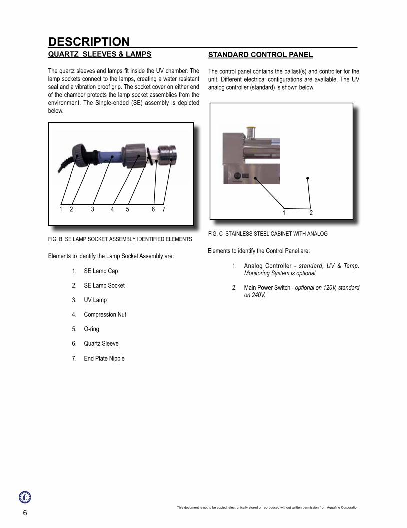
STANDARD CONTROL PANEL
The control panel contains the ballast(s) and controller for the unit. Different electrical configurations are available. The UV analog controller (standard) is shown below.
QUARTZ SLEEVES & LAMPS
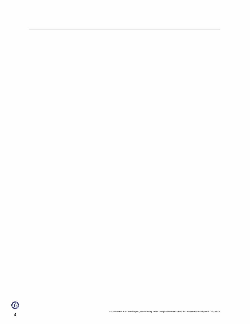
The quartz sleeves and lamps fit inside the UV chamber. The lamp sockets connect to the lamps, creating a water resistant seal and a vibration proof grip. The socket cover on either end of the chamber protects the lamp socket assemblies from the environment. The Single-ended (SE) assembly is depicted below.
Elements to identify the Lamp Socket Assembly are:
DESCRIPTION
FIG. B SE LAMP SOCKET ASSEMBLY IDENTIFIED ELEMENTS
1. SE Lamp Cap
2. SE Lamp Socket
3. UV Lamp
4. Compression Nut
5. O-ring
6. Quartz Sleeve
7. End Plate Nipple
FIG. C STAINLESS STEEL CABINET WITH ANALOG
1. Analog Controller - standard, UV & Temp. Monitoring System is optional
2. Main Power Switch - optional on 120V, standard on 240V.
1 2 3 4 5 6 7 1 2
Elements to identify the Control Panel are:

p 661.257.4770 or 800.423.3015 (outside CA within domestic US) www.aquafineuv.com © Aquafine Corporation 2005 All rights reserved. 7
INSTALLATIONINSTALLATION GUIDELINESThe following are the guidelines and procedures for installing the CSL Series.
locationA. Install the UV treatment unit in a horizontal position in a
sheltered, well ventilated area. Ambient temperatures surrounding the unit should be between 50° (10°C) and 100°F (38°C). For operating temperatures below 50° (10°C) or should your requirements differ, please contact your local Aquafine representative or call Aquafine customer service.
B. Operating water temperature should be between 50° (10°C) and 100°F (38°C).
C. Remove the plastic dowel placed inside the treatment chamber unit, used for securing the baffle during shipping.
D. Protect the equipment form the environment. Do not expose the equipment to direct water spray.
E. As an ultraviolet UV treatment unit does not introduce any chemical residue within the water, it is desirable to install the unit as close as possible to the point-of-use in order to avoid potential recontamination by discharge pipes, fitting, etc.
F. The base of the UV treatment unit should be mounted on suitable support to avoid undue strain on the unit or related pipes and fittings.
G. Allow sufficient service access clearance, at least 72” (183cm) of clearance on the lamp-changing end of the unit. At the opposite end, there should be a minimum of 24” (61cm) of clearance for maintenance. Refer to mechanical drawings. Clearance for servicing the electrical cabinet should be allowed.
electrical power
A. Bring you wiring to the cable entry hole in the back of the cabinet, making sure your electrical service matches the electrical data shown on the nameplate decal. The unit’s main fuse provides primary over-current protection. See the wiring diagram located in the back of the manual.
B. Locate the optional “ON/OFF” switch near the UV treatment unit so the current may be conveniently turned “OFF” for servicing.
NOTE: It is imperative that the unit be properly grounded for safe and proper operation. FAILURE TO PROPERLY GROUND THE UV TREATMENT UNIT AUTOMATICALLY VOIDS ALL EQUIPMENT WARRANTY.
plumbing
A. Limit overhead piping load to 50lbs (22.7kg) per flange. If your piping system is subject of impulse pressure resulting in “water hammer” condition, a surge tank or other means must be provided to remove this condition; otherwise the extreme momentary pressure may rupture and fracture the quartz sleeves.
C. The power requirements for each unit depends on the number and type of lamps used in the treatment chamber.
D. The units incoming power (120VAC or 240VAC) requires a single phase, grounded neutral source. If the unit needs to be powered by a 208VAC supply, an externally mounted step up transformer can be provided. Failure to properly ground the UV treatment unit automatically voids all equipment warranty.
E. If the external transformer is factory installed local to the electrical enclosure,the secondary terminations are factory wired by Aquafine.
F. If the external transformer is required, the transformer primary connections to the customers incoming power shall be made in conformance to the local codes and be consistent with good electrical practice.
G. UV performance is line voltage sensitive. Line voltage should be +5% of rating shown on the electrical nameplate decal. Voltage outside these limits will affect the performance of the UV equipment.
H. Control wiring should reference the appropriate wiring diagram. Control wiring is based upon customer requirements and installed options.
I. Provide an electrical disconnect switch to the unit if it is not supplied. During service and maintenance, the electrical power must be removed.

8
B. Verify the location is free from vibration, which could be caused by proximity to heavy equipment and the erratic or improper pumps. Excessive vibration will damage internal electrical components and cause premature failure of the UV lamps.
C. Install a drain valve and pipe to drain.
D. Install sample port valves, if equipped.
E. All units are rated for a maximum operating pressure of 120psig (8.24 bar). If your unit has the High Pressure Modification option (model suffix “HP”), operating pressure may increase to 150psig (10.34 bar).
F. Ultra pure water users have reported that over time, exposure to ultraviolet light may photochemically degrade nonmetallic piping materials, including most or all fluoro-polymers, resulting in a material breakdown and/or structural failure. Should your water application and piping material be so classified, we recommend that you install “UV light traps” to isolate any susceptible material from direct exposure to the ultraviolet light. Install the UV light trap to the inlet/outlet of the UV treatment chamber prior to the connection of any non-metallic piping.
G. After installation of quartz sleeves, always pressure test the system prior to installation of the UV lamps.and applying electrical power. During pressure testing, DO NOT stand in direct line with quartz sleeves.
H. Before start-up, flush the UV unit and discharge piping to rinse out debris left from installation.
I. The UV chamber should be filled with water.
INSTALLATION
Should your requirements differ, please contact your local Aquafine representative or Aquafine Customer Service.
p 661.257.4770 or 800.423.3015 (outside CA within domestic US) www.aquafineuv.com © Aquafine Corporation 2005 All rights reserved. 9
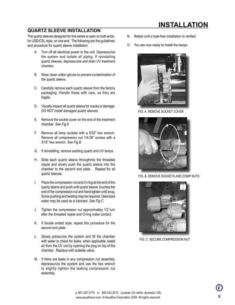
INSTALLATIONQUARTZ SLEEVE INSTALLATIONThe quartz sleeves designed for this series is open on both ends, for USD/CSL style, on one end. The following are the guidelines and procedure for quartz sleeve installation.
A. Turn off all electrical power to the unit. Depressurize the system and isolate all piping. If reinstalling quartz sleeves, depressurize and drain UV treatment chamber.
B. Wear clean cotton gloves to prevent contamination of the quartz sleeve.
C. Carefully remove each quartz sleeve from the factory packaging. Handle these with care, as they are fragile.
D. Visually inspect all quartz sleeve for cracks or damage. DO NOT install damaged quartz sleeves.
E. Remove the socket cover on the end of the treatment chamber. See Fig A
F. Remove all lamp sockets with a 5/32” hex wrench. Remove all compression nut 1/4-28” screws with a 3/16” hex wrench. See Fig B
G. If reinstalling, remove existing quartz and UV lamps.
H. Slide each quartz sleeve throughinto the threaded nipple and slowly push the quartz sleeve into the chamber to the second end plate . Repeat for all quartz sleeves.
I. Place the compression nut and O-ring at the end of the quartz sleeve and push until quartz sleeve touches the end of the compression nut and hand tighten until snug. Some pushing and twisting may be required. Deionized water may be used as a lubricant. See Fig C
J. Tighten the compression nut approximatley 1/2 turn after the threaded nipple and O-ring make contact.
K. If double ended style, repeat this procedure for the second end plate.
L. Slowly pressurize the system and fill the chamber with water to check for leaks, when applicable, beeld air from the UV unit by opening the plug on top of the chamber. Replace with suitable valve..
M. If there are leaks in any compression nut assembly, depressurize the system and use the hex wrench to slightly tighten the leaking compression nut assembly.
FIG. B REMOVE SOCKETS AND COMP NUTS
FIG. A REMOVE SOCKET COVER
FIG. C SECURE COMPRESSION NUT
N. Retest until a leak-free installation is verified.
O. You are now ready to install the lamps.

10This document is not to be copied, electronically stored or reproduced without written permission from Aquafine Corporation.
p 661.257.4770 or 800.423.3015 (within domestic U.S.A & Canada) www.aquafineuv.com © Aquafine Corporation 2010. All rights reserved. 11
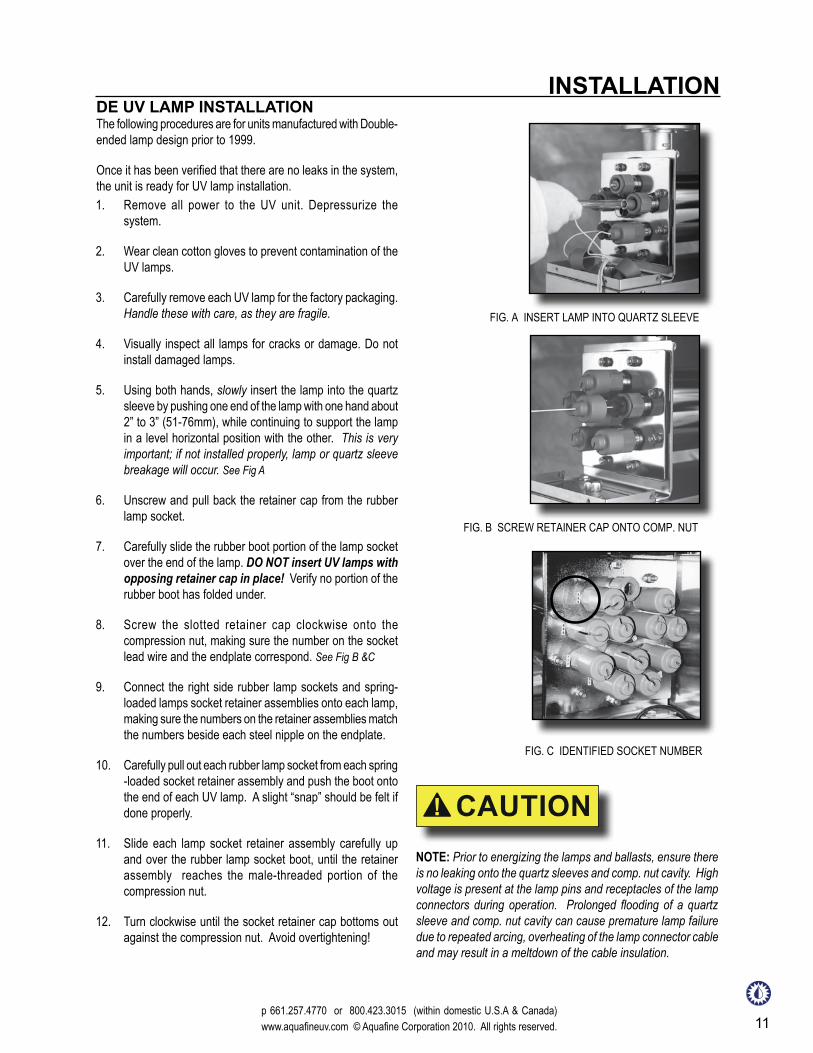
INSTALLATIONDE UV LAMP INSTALLATIONThe following procedures are for units manufactured with Double-ended lamp design prior to 1999.
Once it has been verified that there are no leaks in the system, the unit is ready for UV lamp installation.1. Remove all power to the UV unit. Depressurize the
system.
2. Wear clean cotton gloves to prevent contamination of the UV lamps.
3. Carefully remove each UV lamp for the factory packaging. Handle these with care, as they are fragile.
4. Visually inspect all lamps for cracks or damage. Do not install damaged lamps.
5. Using both hands, slowly insert the lamp into the quartz sleeve by pushing one end of the lamp with one hand about 2” to 3” (51-76mm), while continuing to support the lamp in a level horizontal position with the other. This is very important; if not installed properly, lamp or quartz sleeve breakage will occur. See Fig A
6. Unscrew and pull back the retainer cap from the rubber lamp socket.
7. Carefully slide the rubber boot portion of the lamp socket over the end of the lamp. DO NOT insert UV lamps with opposing retainer cap in place! Verify no portion of the rubber boot has folded under.
8. Screw the slotted retainer cap clockwise onto the compression nut, making sure the number on the socket lead wire and the endplate correspond. See Fig B &C
9. Connect the right side rubber lamp sockets and spring-loaded lamps socket retainer assemblies onto each lamp, making sure the numbers on the retainer assemblies match the numbers beside each steel nipple on the endplate.
10. Carefully pull out each rubber lamp socket from each spring -loaded socket retainer assembly and push the boot onto the end of each UV lamp. A slight “snap” should be felt if done properly.
11. Slide each lamp socket retainer assembly carefully up and over the rubber lamp socket boot, until the retainer assembly reaches the male-threaded portion of the compression nut.
12. Turn clockwise until the socket retainer cap bottoms out against the compression nut. Avoid overtightening!
FIG. B SCREW RETAINER CAP ONTO COMP. NUT
FIG. A INSERT LAMP INTO QUARTZ SLEEVE
FIG. C IDENTIFIED SOCKET NUMBER
NOTE: Prior to energizing the lamps and ballasts, ensure there is no leaking onto the quartz sleeves and comp. nut cavity. High voltage is present at the lamp pins and receptacles of the lamp connectors during operation. Prolonged flooding of a quartz sleeve and comp. nut cavity can cause premature lamp failure due to repeated arcing, overheating of the lamp connector cable and may result in a meltdown of the cable insulation.

12This document is not to be copied, electronically stored or reproduced without written permission from Aquafine Corporation.
SE UV LAMP INSTALLATION SE UV LAMP INSTALLATIONThe following procedures are for units manufactured with Single-ended (SE) lamp design. Once it has been verified that there are no leaks in the system, the unit is ready for UV lamp installation.
1. Remove all power to the UV unit. Depressurize the system.
2. Wear clean cotton gloves to prevent contamination of the UV lamps.
3. Carefully remove each UV lamp from the factory packaging. Handle these with care, as they are fragile.
4. Visually inspect all lamps for cracks or damage. Do not install damaged lamps.
5. Using both hands, slowly insert the lamp into the quartz sleeve by pushing one end of the lamp with one hand, while continuing to support the lamp in a level horizontal position with the other. This is very important; if not installed properly, lamp or quartz sleeve breakage will occur.
6. Twist the lamp into the locking mechanism of the compression nut. This ensures that the lamp is secure within the quartz sleeve. See Fig A
7. Each lamp socket is identified with a number that corresponds to each lamp position marked on the end plate. Match the lamp socket and connect to the appropriate lamp. See Fig B
8. The pins in the lamp must be pushed down to fit securely into the lamp socket connector.
9. Rotate and screw the lamps socket cap into place. Only hand tightening is required. DO NOT OVERTIGHTEN! See Fig C
NOTE: Prior to energizing the lamps and ballasts, ensure there is no leaking water into the quartz sleeves and comp. nut cavity. High voltage is present at the lamp pins and receptacles of the lamp connectors during operation. Prolonged flooding of a quartz sleeve and comp. nut cavity can cause premature lamp failure due to repeated arcing, overheating of the lamp connector cable and may result in a meltdown of the cable insulation.
FIG. C SCREW RETAINER CAP ONTO COMP. NUT
FIG. A INSERT LAMP INTO QUARTZ SLEEVE
FIG. B IDENTIFIED LAMP SOCKET NUMBER

p 661.257.4770 or 800.423.3015 (within domestic U.S.A. and Canada) www.aquafineuv.com © Aquafine Corporation 2009. All rights reserved. 13
INSTALLATION HT LAMP INSTALLATIONThe following procedures are for units High Temperature (HT) units. Since it has been verified that there are no leaks in the system, the unit is ready for UV lamp installation.
1. Remove all power to the UV unit. Depressurize the system.
2. Wear clean cotton gloves to prevent contamination of the UV lamps.
3. Carefully remove each UV lamp for the factory packaging. Handle these with care, as they are fragile.
4. Visually inspect all lamps for cracks or damage. Do not install damaged lamps.
5. Using both hands, slowly insert the lamp into the quartz sleeve by pushing one end of the lamp with one hand, while continuing to support the lamp in a level horizontal position with the other. This is very important; if not installed properly, lamp or quartz sleeve breakage will occur.
6. Place the PVC alignment plate on one end and secure in place with lock nuts.
7. Guide each lamp into the lamp socket, making sure you have a firm and complete connection.
8. Place the PVC alignment plate onthe opposite end of the disinfection chamber and align, making sure you have a
NOTE: Prior to energizing the lamps and ballasts, ensure there is no leaking onto the quartz sleeves and comp. nut cavity. High voltage is present at the lamp pins and receptacles of the lamp connectors during operation. Prolonged flooding of a quartz sleeve and comp. nut cavity can cause premature lamp failure due to repeated arcing, overheating of the lamp connector cable and may result in a meltdown of the cable insulation.
firm connection of all lamps and lamp sockets.
9. Secure the PVC alignment plate into postion with the lock nuts. Improper connection could cause failure of UV lamp operating.
10. Place each socket cover near the ends of the disinfection unit and connect the two fan wires with the two power wires supplied from the unit base. Secure the socket cover to the disinfection cabinet with the screws that are provided..
Fig. A High Temperature UV Unit

14This document is not to be copied, electronically stored or reproduced without written permission from Aquafine Corporation.
p 661.257.4770 or 800.423.3015 (within domestic U.S.A. and Canada) www.aquafineuv.com © Aquafine Corporation 2009. All rights reserved. 15
1. Release the pressure in the UV treatment chamber before attempting to remove the protective covers and sealing items.
2. Disconnect all power to the UV unit before servicing. The unit operates on high voltage and should only be serviced by qualified personnel.
3. Do not allow the unit to overheat by operating without water flow. Standard flow rates are based on water temperatures of 50°F (10°C) to 100°F (38°C). For applications outside these temperatures, contact customer service for assistance. In no case should the water temperature be below 50°F (10°C). For heat sanitization above 170°F (77°C) up to a maximum of 194°F (90°C), stainless steel compression nuts are recommended in place of CPVC compresion nuts. During heat sanitization, the S-254 probe must be removed. (Adaptor for maintaining Hydrostatic seal during sanitization is avilable.) The selection of elastomers should be condsidered.
4. Intermittent operation is allowed as long as the water temperature does not exceed 120°F; optional devices ( T-120 or monitoring systems) are available to prevent this problem. Should the unit be used for batch flow operations, it can be turned “ON” and “OFF” manually. Make sure the unit is allowed to warm up for at least 3 minutes before use, and make sure the unit it turned “OFF” after each session.
5. Do not allow the flow to exceed the maximum rated capacity.
6. DO NOT electrically cycle the unit more than 3 “ON/OFF” cycles in a 24 hour period. Cycling more than this will reduce End-of-Life output and/or premature lamp failure.
OPERATIONOPERATIONAL GUIDELINES
NOTE: DO NOT look at lighted UV lamps. DO NOT operate the UV lamps outside of the UV treatment chamber. EXPOSURE CAN SEVERELY BURN AND DAMAGE EYES AND SKIN!
powering up
A. The UV chamber should be filled with water. The flow of water for the initial filing should not exceed 50 GPM. Failure to comply may result in quartz sleeve breakage. Ensure there are no system leaks and no piping connection leaks.
B. All earth ground connections are properly made.
C. All lamp connections are properly made.
Prior to turning on the UV unit, the following must be verified:
D. The socket cover is secured to the end of the UV treatment unit.
E. Verify that all incoming power conductors, including the ground conductor, are properly terminated.
F. Setting local or remote operation on the controller.
G. If system is set in local operation, pressing the start/stop key will switch the UV lamps ON/OFF.
H. If the system is operating in the remote mode, the customer must wire external electrical power to activate the system. The external electrical power specified will be based upon the order.

16This document is not to be copied, electronically stored or reproduced without written permission from Aquafine Corporation.
p. 661.257.4770 or 800.423.3015 (within domestic U.S.A. & Canada) www.aquafineuv.com © Aquafine Corporation 2009 All rights reserved. 17
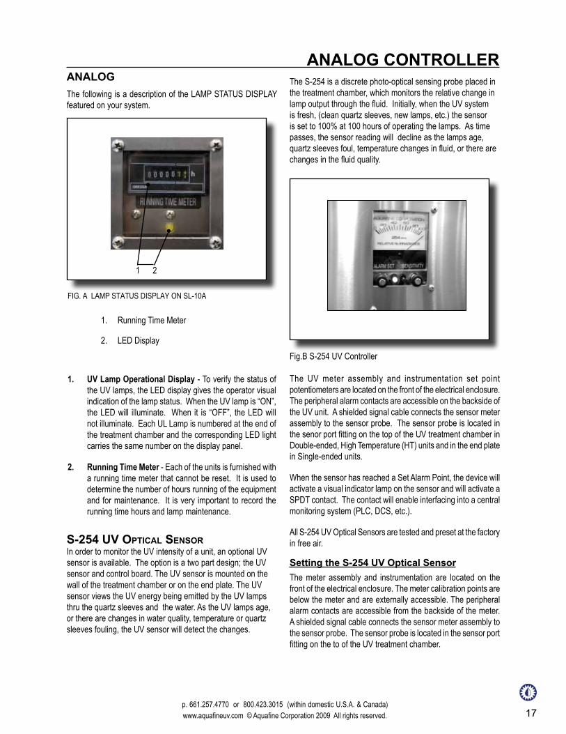
ANALOG CONTROLLERANALOGThe following is a description of the LAMP STATUS DISPLAY featured on your system.
1. UV Lamp Operational Display - To verify the status of the UV lamps, the LED display gives the operator visual indication of the lamp status. When the UV lamp is “ON”, the LED will illuminate. When it is “OFF”, the LED will not illuminate. Each UL Lamp is numbered at the end of the treatment chamber and the corresponding LED light carries the same number on the display panel.
2. Running Time Meter - Each of the units is furnished with a running time meter that cannot be reset. It is used to determine the number of hours running of the equipment and for maintenance. It is very important to record the running time hours and lamp maintenance.
FIG. A LAMP STATUS DISPLAY ON SL-10A
1. Running Time Meter
2. LED Display
1 2
S-254 uV optical SenSor In order to monitor the UV intensity of a unit, an optional UV sensor is available. The option is a two part design; the UV sensor and control board. The UV sensor is mounted on the wall of the treatment chamber or on the end plate. The UV sensor views the UV energy being emitted by the UV lamps thru the quartz sleeves and the water. As the UV lamps age, or there are changes in water quality, temperature or quartz sleeves fouling, the UV sensor will detect the changes.
The S-254 is a discrete photo-optical sensing probe placed in the treatment chamber, which monitors the relative change in lamp output through the fluid. Initially, when the UV system is fresh, (clean quartz sleeves, new lamps, etc.) the sensor is set to 100% at 100 hours of operating the lamps. As time passes, the sensor reading will decline as the lamps age, quartz sleeves foul, temperature changes in fluid, or there are changes in the fluid quality.
The UV meter assembly and instrumentation set point potentiometers are located on the front of the electrical enclosure. The peripheral alarm contacts are accessible on the backside of the UV unit. A shielded signal cable connects the sensor meter assembly to the sensor probe. The sensor probe is located in the senor port fitting on the top of the UV treatment chamber in Double-ended, High Temperature (HT) units and in the end plate in Single-ended units.
When the sensor has reached a Set Alarm Point, the device will activate a visual indicator lamp on the sensor and will activate a SPDT contact. The contact will enable interfacing into a central monitoring system (PLC, DCS, etc.).
All S-254 UV Optical Sensors are tested and preset at the factory in free air.
Fig.B S-254 UV Controller
Setting the S-254 UV Optical SensorThe meter assembly and instrumentation are located on the front of the electrical enclosure. The meter calibration points are below the meter and are externally accessible. The peripheral alarm contacts are accessible from the backside of the meter. A shielded signal cable connects the sensor meter assembly to the sensor probe. The sensor probe is located in the sensor port fitting on the to of the UV treatment chamber.

18This document is not to be copied, electronically stored or reproduced without written permission from Aquafine Corporation.
ANALOG CONTROLLER 1. Gradually start at the normal flow rate.
2. Bring the unit up to normal operating pressure and temperature.
3. Turn the UV lamps for a minimum of 15 minutes.
4. Adjust the sensitivity potentiometer to 100%.
5. Adjust the sensitivity potentiometer to specified %, determined by lamp type.
6. Adjust the alarm potentiometer until the RED LED barley illuminates.
7. Set the sensitivity potentiometer back to 100%.
8. Turn the sensitivity potentiometer to specified %, determined by lamp type; the LED should illuminate.
9. Turn the sensitivity potentiometer back to 100%.
NOTE: Resetting must be performed after the first 100 hours of operation on new UV lamps, both at the time of installation and replacement.
Alarm Contacts“Normally CLOSED” and “Normally OPEN” alarm contacts are also provided for use with the user-supplied peripheral equipment, such as remote alarms of solenoid valves. Dry relay contacts are rated as follows: 0.52 AMP 120V AC., 0.25 AMP 240V AC.
If your application requires higher contact ratings, use a slave relay. Connection of peripheral equipment is the responsibility of the user.
Sensor AlarmThe S-254 UV Optical Sensor provides information about the relative amount of UV passing through the water. When the UV intensity falls below the minimum standard due to changes occurring in the normal operating flow rate, temperature, operating pressure or quality of the fluid flowing through the system, the RED Sensor Alarm light (LED) will turn “ON”. Corrective action must be taken when this happens to optimize the performance of the UV treatment unit.
1. Examine your system for any significant changes in normal operating conditions.
2. Check if all UV lamps are electrically operating and/or need replacement.
4-20ma SenSor SignalThe option is available with the S-254 UV Optical Sensor. It generates a 4-20mA output signal based upon the relative UV intensity, which may be monitored at a remote panel or control PC. The customer is responsible for providing an appropriate 4-20mA display instrument and connecting it.
3. Verify the quartz sleeves are clean. If the fouling of the quartz sleeve is the cause of the alarm activation, the quartz must be cleaned and at the same time, the UV sensor probe quartz window.
t-120 temperature controller Ultra violet lamps produce heat. The heat within the treatment chamber must be dissipated to prevent damage to the UV unit and water systems. Sealing material such as gaskets, o rings, compression nuts, lamp sockets, UV lamps and UV sensor can be damaged due to excessive heat. Under normal operating conditions, the water flow is sufficient to remove heat generated by the lamps.
As a safety feature, in which there maybe no flow conditions or intermittence operation, a T-120 temperature control device maybe installed.
StanDarD unitS:Typically the temperature device is located on the water inlet end plate, in some cases it is mount on the treatment chamber wall. No operator intervention is required. When the temperature sensor reaches 120°F (49°C), the UV lamps will automatically switch OFF, preventing overheating conditions. When the temperature drops below 100°F (38°C), the lamps will automatically restart.
HigH temperature (Ht) unitS:When the temperature sensor reaches 170°F (77°C), the UV lamps will automatically switch OFF, preventing overheating conditions. When the temperature drops below 150°F (66°C), the lamps will automatically restart.
This temperature spread prevents excessive START/STOP’s during no flow conditions and protects the UV lamps and electrical components from overheating damage.
The temperature probe is located in the inlet riser. No operater intervention is required other than periodic visual verification that the UV lamps(s) are operating properly under normal flow conditions.
The cutoff temperature has been preset at the factory. Should you require a different set point, please contact Aquafine.

p 661.257.4770 or 800.423.3015 (within domestic U.S.A. and Canada) www.aquafineuv.com © Aquafine Corporation 2009. All rights reserved. 19
UV & TEMP MONIT. SYSTEM OPERATIONUV & TEMPERATURE MONITORING SYSTEM
SetupSoftware set up procedure will require accessing the main menu.
1. a) Depressing the UP arrow will cycle to each digit.
2. b) When the digit is achieved – Depress the DOWN arrow to move to the next digit position.
3. c) Repeat procedure until all four digits indicate the correct password.
4. d) Then depress ENTER.
5. e) The Display will indicate “MAIN MENU”.
1. The UV intensity display, (“UV DISPLAY”) A. RELATIVE – Display of relative intensity 0-100% B. ABSOLUTE – Display absolute intensity 0-5000 µw/cm²
Alarm Display ScreenThe first line of the alarm display indicates the relative UV intensity alarm set point. The second line indicates temperature alarm set point. This display is accessed by pressing the UP arrow when in the main display.
There will be an BEEP sound as the unit is initialized. The Monitoring station is a combination UV and temperature controller. The signals from the detector are displaying the UV intensity and water temperature. Each of values may have a corresponding alarm set point.
The first line of the main menu screen indicates the UV intensity in relative or absolute units. The second line indicates water temperature in °F or °C.
Main Menu Screen
A lighted LCD screen and three flush push buttons are on the faceplate. Buttons to identify the controller are: See Fig. A.
FIG. A UV MONITORING STATION FACEPLATE
1 2 3
1. UP arrow
2. DOWN Arrow
3. ENTER - access to MAIN MENU and OPTIONS
This process is started by depressing the “ENTER” button, and then entering the password.
The password “1234” is entered by:
MAIN MENU
From the “MAIN MENU” the following parameters can be accessed. To modify or change these parameters follow the steps described in “Setting Parameters”.
ACCESSING PARAMETERS
20This document is not to be copied, electronically stored or reproduced without written permission from Aquafine Corporation.
UV & TEMP MONIT. SYSTEM OPERATION 2. The UV intensity alarm set point (“UV ALARM”)
A. ON (set point) – To enable UV alarm (DEFAULT) B. EDIT – Select UV alarm set point 20-90% C. OFF – disable UV alarm
3. Setting the UV 100% value, (“UV 100% LEVEL”) A. DIRECT– Sets 100% UV (current value of absolute intensity) B. EDIT – Sets 100% to entered absolute intensity value
4. The temperature display, (“TEMP DISPLAY”) A. FAHRENHEIT - select temperature unit of measurement B. CELSIUS - select temperature unit of measurement C. OFF - disable temperature measurement
5. The temperature alarm set point, (“TEMP ALARM”) A. 120ºF (49ºC) - set temp alarm to 120°F (DEFAULT) B. 170ºF (77ºC) - set temp alarm to 170°F C. OFF – disable temperature alarm
1. Access “Main Menu”’
2. Use the UP/DOWN arrows to scroll to “UV DISPLAY” in the sub-menu – “ENTER”
3. Use the UP/DOWN arrows to scroll to “RELATIVE” in sub menu – “ENTER” or “ABSOLUTE” as indicated – “ENTER”
4. The display will indicate “MAIN MENU” with sub
The following steps will specify how to set each parameter of the monitoring station. After a parameter is set, the operator will be instructed to select “RETURN” once or twice to return to the operating screen. The operating screen will have the UV intensity displayed on the first line, and the temperature displayed on the second line.
SETTING PARAMETERS
Setting UV Intensity Display (Absolute µw/cm²or Relative %)
menu indicating “UV DISPLAY”
5. Use the UP/DOWN arrows to scroll to “RETURN” – “ENTER”
6. The display should be at the main operating screen indicating UV intensity and temperature
1. Access “Main Menu”’
2. Use the UP/DOWN arrows to scroll to “UV ALARM” – “ENTER”
3. Use the UP/DOWN arrows to scroll to “EDIT” – “ENTER”
4. Use the UP/DOWN arrows to scroll to preferred UV alarm threshold percentage – “ENTER”
5. Verify main menu line indicates “UV ALARM” and the sub menu indicates “ON( XX %)”
6. Note the ‘XX’ indicates selected value
7. Use the UP/DOWN arrows to scroll to “RETURN” – “ENTER”
8. Then again scroll to “RETURN” – “ENTER”
9. The display should be at the main operating screen indicating UV intensity and temperature
Setting UV Alarm Setpoint
The alarm point will be a number between 20-90%. The selection is typically based upon the lamp type and operating conditions. Typical alarm set point values for equipment with HX lamps are 80% and with standard lamps, 60%.
Setting 100% UV
Typically the UV Monitoring station intensity is set to 100% UV when new lamps and quartz sleeves have been installed and the system is operating under “normal operating conditions” (flow, temperature and water quality).
1. Use the UP/DOWN arrows to scroll to UV 100% LEVEL” is indicated in the sub menu – “ENTER”
2. The main menu will indicate “UV LEVEL”
3. Use the UP/DOWN arrows to scroll to “DIRECT” in the sub menu – “ENTER”

p 661.257.4770 or 800.423.3015 (within domestic U.S.A. and Canada) www.aquafineuv.com © Aquafine Corporation 2009. All rights reserved. 21
UV & TEMP MONIT. SYSTEM OPERATION4. The main menu will indicate “UV LEVEL”, the sub
menu will display an actual UV intensity value – “ENTER”
5. The “MAIN MENU” will be displayed, with sub menu displaying “UV 100% LEVEL”
6. Use the UP/DOWN arrows to scroll to “RETURN” – “ENTER”
7. The display should be at the main operating screen indicating UV intensity and temperature
1. Access “Main Menu”’
2. Use the UP/DOWN arrows to scroll to “TEMP DISPLAY” – “ENTER”
3. Use the UP/DOWN arrows to scroll to desired temperature °F, °C or OFF. – “ENTER”
4. Verify main menu line indicates “MAIN MENU”
5. Use the UP/DOWN arrows to scroll to “RETURN” – “ENTER”
6. The display should be at the main operating screen indicating UV intensity and temperature
Setting Temp. Units (°F or °C)
Setting Temp. Alarm Setpoint
The temperature alarm point is normally set to 120°F. High temperature units are special equipment in which the set pint is 170°F. If the temperature alarm is set to OFF, this will disable the temperature control feature and damage to the unit can occur.
1. Access “Main Menu”
2. Use the UP/DOWN arrows to scroll to “TEMP ALARM” – “ENTER”
3. Use the UP/DOWN arrows to scroll to 120°F (default) , 170°F or OFF – “ENTER”
4. Verify display indicates main menu indicates “MAIN MENU”, and the sub menu indicates “TEMP ALARM”
5. Use the UP/DOWN arrows to scroll to “RETURN” – “ENTER”
6. Then again scroll to “RETURN” – “ENTER”
7. The display should be at the main operating screen indicating UV intensity and temperature
ALARM INDICATIONS
Low UV Alarm
When the detector measures UV below the low UV alarm set point, the controller will activate the following:
1. There will be an audio alarm once every second for 30 seconds.
2. The LCD screen flashes blue. The screen will remain flashing BLUE until the UV Intensity level adjusts above the threshold or the alarm is disabled.
3. The low UV output relays will change state.
4. To disable the alarm, refer to “Setting UV Alarm Setpoint” and use the UP/DOWN arrows to scroll to OFF.
High Temp. Alarm
When the detector senses a temperature above the high temperature set point, the controller will actuate the following:
1. There will be an audio alarm once every second for 30 seconds.
2. The LCD screen flashes RED. The screen will remain flashing RED until the temperature alarm is corrected.
3. The temperature output relays will change state.
4. To disable the alarm, refer to “Setting Temp. Alarm Setpoint” and use the UP/DOWN arrows to scroll to OFF.
22This document is not to be copied, electronically stored or reproduced without written permission from Aquafine Corporation.

p 661.257.4770 or 800.423.3015 (within domestic U.S.A. and Canada) www.aquafineuv.com © Aquafine Corporation 2009. All rights reserved. 23
MAINTENANCERECOMMENDED MAINTENANCE GUIDELINES
• Water quality (tap water, DI water, pH level, chemical content, solids, etc.)
• Entering water temperature
• Flow rate (high, low or constant)
• Process status (continuous, intermittent)
Keep in mind that operating conditions can differ substantially for identical UV models even within the same building due to such variables as:
1. Performance monitoring.
2. Recognizing the need for time based preventative measures.
3. Organized analysis of performance, based on your particular operational environment.
4. Establishing optimum parameters for periodic replacement of vital components.
The following provides users of Aquafine UV treatment equipment with recommendations and procedures that will maximize the efficiency, consistency, reliability and longevity of the equipment. Once the equipment is properly installed and fully operational, this will provide time-oriented guidelines for:
Because of these variable, each UV unit may have to be serviced differently. For instance, those with continuous high flow, or with lower quality water require more frequent cleaning of the quartz sleeves than those exposed to cleaner water, lower flow rates and/or intermittent usage.
Regarding UV lamp replacement, the rule is to replace the lamps every 8,000 hours or every 24 months, whichever comes first. Meaning, units which are continuously used for 24 hours a day, will reach 8,000 hours within 375 days, or slightly over 1 year. This excludes HX lamps, which have a lamp life of 9,000 hours.
The following table represents the recommended Preventative Maintenance (PM) for the equipment.
PREVENTATIVE MAINTENANCE SCHEDULEMaintenance initial Start-up Daily/Monthly annually
operating conDitionS X X
cleaning tHe unit X X
quartz SleeVe maintenance
X X X
cleaning tHe Detector winDow
X X X
inSpection for leakS X X X
Set Detector 100% X X
inSpection for lamp operation
X X X
replacement of uV lampS X
lamp Socket inSpection X
cooling fan inSpection X X X
The most important consideration for proper installation, operation and maintenance of any piece of equipment is operator safety. The following caution statements directly relate to operator safety. Please review with all applicable personnel to ensure continuous compliance.

24This document is not to be copied, electronically stored or reproduced without written permission from Aquafine Corporation.
SAFETY REQUIREMENTS
A. Never look at lighted ultraviolet lamps. Never operate the ultraviolet lamps outside the UV treatment chamber. UV lamp exposure can severely burn and damage eyes and skin.
B. Properly ground the UV treatment unit. Failure to do so can result in severe electrical shock hazard.
C. Provide watertight piping and compression nut seal. Failure to do so can cause damage to electrical components, as well as create an electrical hazard to operating personnel.
D. Disconnect power before servicing unit. The UV lamps and electrical components are operated with high voltage electrical power. DO NOT attempt to service the UV treatment unit without first disconnecting power to the unit. Shut off the source of power at the equipment main panel breaker and use appropriate tag-out or lockout procedures to prevent accidental power-up by other personnel. Only qualified personnel should perform service.
E. Remove pressure before servicing unit. The UV unit has components under pressure.
The following safety requirements are mandatory. Failure to carefully follow them can cause injury to the operator and damage to the UV unit.
operating conDitionS
SAFETY REQUIREMENTSTO BE OBSERVED AT ALL TIMES
Never operate the unit for more than 20 minutes without flow of water. Elevated water temperatures can be dangerous and damaging to the unit. Do not exceed three (3) “START/STOP” cycles per 24-hour period; otherwise lamp filaments will be subjected to excessive thermal stress, which could cause premature failure.
cleaning tHe unit
1. Depending on the environment of the installation, clean the exterior surfaces of the UV treatment chamber, and electrical enclosure. The frequency of cleaning will be dependent upon the environmental condition. In some cases, it may be necessary to clean the unit from once a month to yearly.
2. Use a soft cloth with soap and water, or any commercial stainless steel cleaner.
3. Avoid scratching the display screen.
4. Interior of the electrical cabinet should be inspected for debris. Any dirt, dust or external material should be removed with a vacuum. The electrical terminal should be cleaned with a commercial electrical contact cleaner.
As water passes through the UV treatment unit, debris and other matter in the water will settle and deposit on the quartz sleeves. This will impair the ability of the ultraviolet rays to penetrate into the water. Therefore, it is imperative to determine a cleaning schedule for the quartz sleeves. The frequency will depend on the specific type of water being processed, such as it’s turbidity, flow rate, and on the duty cycle, i.e. 24 hour continuous or intermittent at planned or random intervals. Replacement of the quartz sleeves should be completed every 2 years of operation.
Inspect the quartz sleeves one month after the first installation for a good indication of the degree of contamination you can expect over subsequent or longer periods. Then you will be able to determine a reasonable schedule for periodic cleaning.
If the water has been conditioned through deionization, reverse osmosis or distillation, the cleaning frequency can be set at once per year. If clear, fresh water is used, the cleaning frequency should be anywhere from once every thirty days to once every six months. With super clean water, this can be extended even further. Determine cleaning frequency by visually inspecting any one quartz sleeve to see how much debris or film has settled on the outside of it.
Clean In Place (CIP) cleaning is sometimes effective in the removal of debris from the sleeves. A test should be completed to determine the effectiveness of a CIP cleaning. After a chemical CIP has been completed, the quartz sleeves should be visually inspected for the removal of material. If CIP is not effective, then a manual cleaning or replacement of the sleeves will be required.
quartz SleeVe maintenance
MAINTENANCE

p 661.257.4770 or 800.423.3015 (within domestic U.S.A. and Canada) www.aquafineuv.com © Aquafine Corporation 2009. All rights reserved. 25
cleaning tHe quartz SleeVeS
1. Turn off the water to the unit.
2. Disconnect the electrical circuit.
3. Drain the UV treatment chamber.
4. Remove the socket cover.
5. Wear clean gloves to prevent contamination of the quartz sleeves and UV lamps.
6. Remove retainer caps and lamp sockets.
7. Remove UV lamps from inside the quartz sleeves.
8. Using the compression nut tool, loosen the compression nuts and carefully remove the quartz sleeves.
9. Wash the quartz sleeves with mild soap and water. Rinse in clean, hot water.
10. The UV Detectorwindow should be cleaned during the quartz sleeve cleaning and maintenance.
The most important consideration for proper installation, operation and maintenance of any piece of equipment is operator safety. The following caution statements directly relate to operator safety. Please review with all applicable personnel to ensure continuous compliance.
Visually inspect the quartz sleeve thirty days after use to see if any debris or film has settled on the outside. If dirty, use the following procedures. Should this be insufficient, they should be replaced.
inSpection for leakS
1. Shut off all electrical power. Shut off source power at the facilities main panel and use appropriate tag-out safety procedures to prevent accidental power-up by other personnel.
2. Remove the socket cover from the leaking end.3. Determine whether the leak comes from one or more
of the lamp socket nipples (leaking quartz tube), or from the main end plate gasket.
To ensure there are no leaks, a visual inspection of the treatment chamber should be made. The source of any leaking should be found and repaired.
Visually inspect the bottom pans at both ends of the cylinder for dripping water. If a leak is detected, follow this procedure:
if tube quartz tube iS leaking
• Release the pressure. Open the drain valve connected to the bottom fitting of the cylinder and drain fluid from the chamber until water level is below the leaking tube.
• Unscrew the lamp socket and lamp form leaking nut.
• Remove compression nut and O-ring from the end of the quartz tube.
• Place new O-ring into the leaking compression nut and reassemble all parts mentioned above in the reverse order.
• Refill the treatment chamber to test all seals before restoring electrical power.
if enD plate o-ring iS leaking
• Do not use any gasket compounds and make sure the O-ring and all seal surfaces are clean before reassembling.
• Torque the perimeter bolts evenly approximately 5-10 ft/lbs. above their present torque, using a cross-symmetrical tightening progression. See the torque label on the end plate.
• If that does not stop the leaking, the gasket/O-ring may require replacement. Remove all UV lamps.
• Remove all quartz sleeves.
• Remove end plate O-ring.
cleaning tHe Detector winDow
1. Shut off the flow and release the pressure.
2. Shut off all power to the UV unit.
3. Remove the cable by twisting the connector terminal counterclockwise. The connector will slide off.
4. Unscrew the Detector.
5. Use a lint-free cloth with alcohol and very carefully wipe the lens face on the front of the Detector.
6. Replace the Detector and the cable.
7. Turn the power “ON” and resume operation.
MAINTENANCE
26This document is not to be copied, electronically stored or reproduced without written permission from Aquafine Corporation.
inSpection for lamp operation
A visual check of the Lamp Status screen should be made.
The UV lamps are rated for 8,000 hours or every 24 months, whichever comes first. This means that the units, if continuously used for 24 hours a day, will reach 8,000 hour limit within 365 days, or slightly over 1 year. This excludes HX lamps, which have a lamp life of 9,000 hours. After this time, the lamp glass will photo chemically change and no longer allow sufficient 254 N.M. short wave UV, the germicidal ray of the lamp, through the glass to effectively kill bacteria.
replacement of uV lampS
NOTE: The Lamp Out Alert alarm and function will not activate after the first 30 seconds of operation after the lamps have been turned “ON”.
NOTE: Failure to replace the ultraviolet lamps on a timely basis of at least once every 8,000 hours may cause the equipment to fail. With intermittent use, in no case should the UV lamps be used for more than 24 months, regardless of the number of hours of operation, due to normal operational degradation of the UV lamp.
lamp Socket inSpection
1. Be sure all power to the equipment is disconnected.
2. Inspect the condition of the socket retainer caps. If they show signs of cracking or any chemical degradation, they should be replaced.
3. Inspect the condition of the lamp socket (resilient boot) and the metal lamp contact imbedded in the end with the lip seal.
4. Metal contacts must be clean, free of corrosion and straight.
5. Resilient boots must be clean, free of cracks and free of any chemical degradation.
6. Lip seals must be pliable, unbroken and fit snugly over the ceramic lamp sockets.
7. The wires must be clean, with all insulation and no signs of brittleness.
If none of the descriptions are prevalent, replace entire lamp socket assembly.
When replacing lamps, inspect the lamp socket contacts and related hardware. They should be inspected for corrosion of the metal contact, deterioration of the metal or burning.
See Controller section: Setting UV Detector to 100%. Set Detector 100%
• Replace O-ring and then reassemble all components in reverse order.
NOTE: Failure to perform quartz sleeve cleaning maintenance may cause inadequate UV treatment and low sensor values. The quartz sleeve maintenance is very important to the overall operation of the equipment. If the quartz sleeves are not properly maintained, the UV efficiency will be reduced.
cooling fan inSpection
While the unit is in normal operating mode, check to see that there is airflow at the exhaust ports and that no obstructions are present. If there is no airflow, the fan(s) should be replaced immediately.
MAINTENANCE
leD DiSplay maintenance - analog not applicable to all units
If an LED bulb does not light after you replace a UV lamp, you need to verify the electrical output of the ballast connected to that specific UV lamp. This is done by testing the ballast open circuit voltage and should be performed by an electrician or qualified facilities personnel. Follow these recomended procedures:
1. Shut the power to the UV unit “OFF”.
2. Remove the socket cover.
3. Identify the faulty UV lamp, which corresponds to the number on the LED display.

p 661.257.4770 or 800.423.3015 (within domestic U.S.A. and Canada) www.aquafineuv.com © Aquafine Corporation 2009. All rights reserved. 27
Sample proceDureS
1. Prior to taking the water sample, have on hand an adequate supply of sterile bottles. These should be obtained from a source laboratory and should have been autoclaved and contained within a plastic outer wrapping.
2. The inside diameter of a sample valve may not exceed 1/4” (6mm) to ensure proper velocity. Prior to taking a sample, it’s imperative that the test sample valve be fully opened under full pressure for a full three and a half minutes. Temporary tubing or some other material may be used to direct the water into a container or drain to avoid unnecessary spillage.
3. After the valve has been left fully open for three and a half minutes, reduce the flow to a reasonable stream of water (not less than 50% of full flow). Continue flowing to drain 3 additional minutes.
4. Remove any temporary tubing used for flow diversion.
5. Open the sterile bottle. Holding the cap in a down position, the operator should then hold his breath while taking the sample so as to avoid atmospheric contamination of the sample. The operator must also not allow any fingers to touch the inside of the cap or neck of the bottle.
6. After the water sample has been taken, the cap should be immediately secured on the sample container.
7. The sample container should be labeled and placed in a plastic wrapping and must be taken to the laboratory for plating as soon as possible. Processing should begin within 3 hours of sample collection and should comply with accepted standard methods.
MAINTENANCE
BALLAST TYPE
120V ELECTRONIC
240V MAGNETIC
240V HE
550-650 575-675 450-850
replacement of ballaStS
Ballast replacement is not part of the UV units routine maintenance. However, in the event that the ballast needs to be replaced, the following procedure should be followed:
1. Shut the power to the UV unit “OFF”.
2. Locate the old ballast to be replaced. Refer to the electrical diagram if necessary.
NOTE: If the voltage reading is zero, or a number above or below the acceptable range, this indicates a ballast fault and the ballast connected to the faulty UV lamp must now be replaced. If the reading is in the accpetable range, but the LED does not light, the LED board has failed and needs to be replaced.
4. Remove the lamps socket(s) from the faulty UV lamp base.
5. Use a voltmeter and set an operating range at >700VAC.
6. Measure the open circuit voltage. For single-ended (SE) UV lamps, connect the voltmeter across the receptacles of the lamp socket. For double-ended (DE) and High Temperature (HT) unit UV lamps, connect one end of the voltmeter to one end of the lamp socket and the other end of the voltmeter to the opposite end of the lamp socket.
7. Turn the power to the UV unit “ON”.
8. Record the reading.
9. Shut the power to the UV unit “OFF”.
10. The open circuit voltage for the various ballasts vary, as noted in the corresponding chart below.
3. Isolate the old ballast from the rest of the system by disconnecting the ballast connector.
4. Remove and discard the old or defective ballast.
5. Install the new ballast.
6. Reconnect the ballast connector(s).
7. Turn the power to the UV unit “ON”.
28This document is not to be copied, electronically stored or reproduced without written permission from Aquafine Corporation.
Every UV unit should be tested periodically to verify actual efficiency. Regardless of the intended application or any optional equipment that may have been provided with the unit, the most accurate and dependable procedure is to conduct post-UV sample analysis in accordance with standard testing methods.
obtaining proper water SampleS
Our experience has shown that the vast majority of unsatisfactory post-UV bacteriological samples are directly related to improper sample taking techniques. There are a variety of commercial sample collection apparatuses available. Should you chose one, be sure to follow the manufacturers recommended procedures.
Optional sample unit fittings on both the intake and discharge UV chamber flange risers can be provided. We recommend you use the fittings to collect “before and after UV” water samples to eliminate the possibility of contamination by nearby piping, fittings, etc. We recommend you select a valve with a discharge orifice no larger than 1/4” (6mm).
meaSuring performance
MAINTENANCE
replacing/cleaning tHe air filter
An air filter, provided for select units, is located at the bottom of the enclosure.
Visually inspect the air filter every 30 days or sooner, depending on the environment of the site installation, to see if any debris or film has settled. If the filter is dirty, the following procedures are provided:
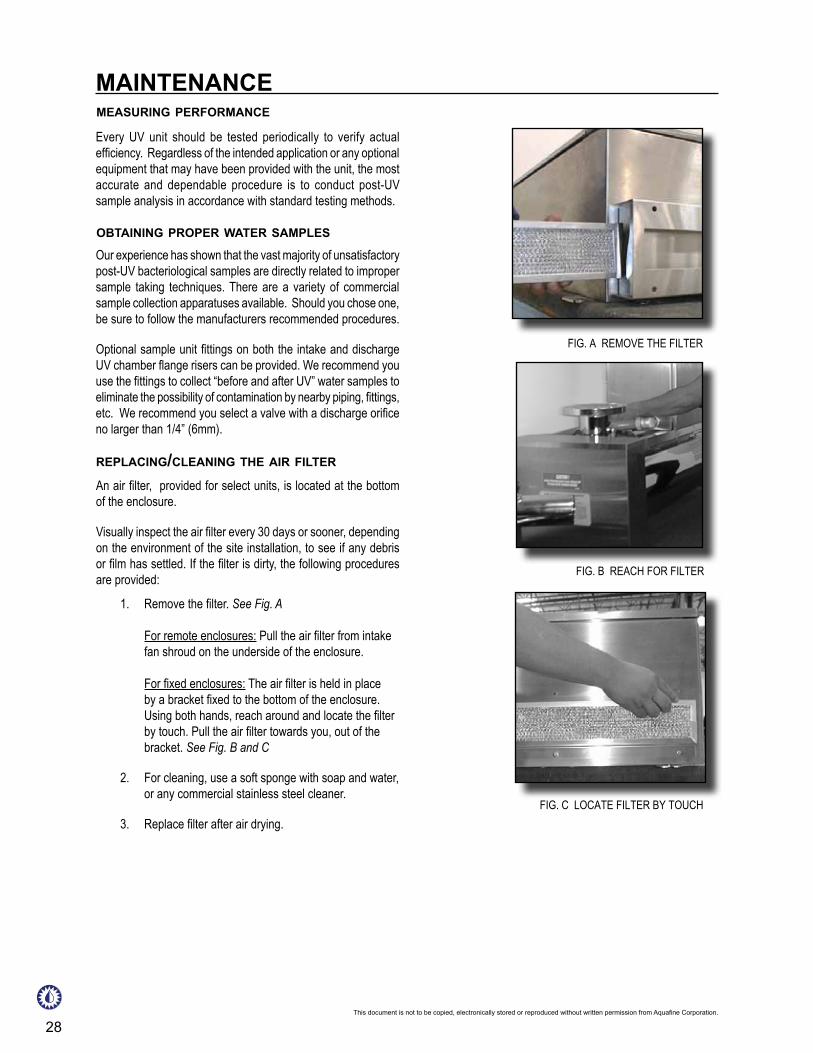
1. Remove the filter. See Fig. A For remote enclosures: Pull the air filter from intake fan shroud on the underside of the enclosure. For fixed enclosures: The air filter is held in place by a bracket fixed to the bottom of the enclosure. Using both hands, reach around and locate the filter by touch. Pull the air filter towards you, out of the bracket. See Fig. B and C
2. For cleaning, use a soft sponge with soap and water, or any commercial stainless steel cleaner.
3. Replace filter after air drying.
FIG. A REMOVE THE FILTER
FIG. C LOCATE FILTER BY TOUCH
FIG. B REACH FOR FILTER

p 661.257.4770 or 800.423.3015 (outside CA within domestic US) www.aquafineuv.com © Aquafine Corporation 2005 All rights reserved. 29
ANALOG TROUBLESHOOTING
LAMP NOT OPERATINGSYMPTOM PROBABLE CAUSE REMEDYLamp is not operating on LED display.
Lamp Failure The UV lamp should be inspected for damage.
Replace UV lamp.Lamp Connection The socket should be inspected to insure that
the lamp connection is tight and no damage is present.
Replace if defective. Ballast In a situation where two consecutive lamps are
out, the ballast may be defective. Each ballasts controls two lamps. Ballast A –lamps l-2, Ballast B –lamps 3-4, Ballast C –lamps 5-6, Ballast D –lamps 7-8, Ballast E –lamps 9-10, Ballast F –lamps 11-12, SSingle channel ballast failures can occur.
Ballast Overheating Each of the ballasts have an overheat circuit. When the ballast temperature reaches the preset temperature, the ballast automatically shuts OFF. When the ballast cools down, the ballast will reenergize.
Excessive continuous heat will destroy the ballast.
LED Board The LED board may be defective, indicating false lamp-out.
SYSTEM NOT OPERATINGSYMPTOM PROBABLE CAUSE REMEDYSystem not operating. T-120 Temperature Controller If T-120 Option: If the unit is equipped with a
T-120, the unit will automatically shut OFF when the temperature exceeds 120°F. When the water temperature cools down to below less than 100°F, the unit will turn back ON.
Blown fuse/circuit breaker Check main fuse or circuit breaker.
A complete inspection to determine the cause of failure should be completed.
GFI Some UV units are equipped with a GFI. Resetting the GFI will restore power to the unit.
Power to the Unit Main power to the unit should be checked.ON /OFF Auto Switch In units wired with remote START/STOP,
capabilities should determine the mode of operation.

30This document is not to be copied, electronically stored or reproduced without written permission from Aquafine Corporation.
TROUBLESHOOTING ANALOG LEAKINGSYMPTOM PROBABLE CAUSE REMEDYLeaking Compression nut Inspect the compression nut and O-ring to insure
that they are installed properly.Over pressure limit System pressure greater than the design pressure
will cause the sealing material to fail.Gasket failure The gasket and O-rings should be inspected for
deterioration.
These materials can be subjected to damage by UV, Ozone and heat.
O-rings The gasket and O-rings should be inspected for deterioration.
These materials can be subjected to damage by UV, Ozone and heat.
Reinstall and replace the O-ring.Sealing material The gasket and O-rings should be inspected for
deterioration.
These materials can be subjected to damage by UV, Ozone and heat.
“Water Hammer” “Water hammer” pressure can be 5-10x’s higher than the static pressure of a water system and can cause leaking and/or breakage to the quartz sleeves.
Broken quartz sleeves Inspect the ends of the sleeves for cracks and chips.
Any broken sleeves should be replaced.Damaged Parts - due to heat If the unit is operating with compression nuts
manufactured with CPVC (gray plastic) and has been exposed to elevated temperatures, the material may be damaged.
Excessive heat can distort the plastic material, resulting in a loss in compression of the O-ring seal.
Change nuts to stainless steel.
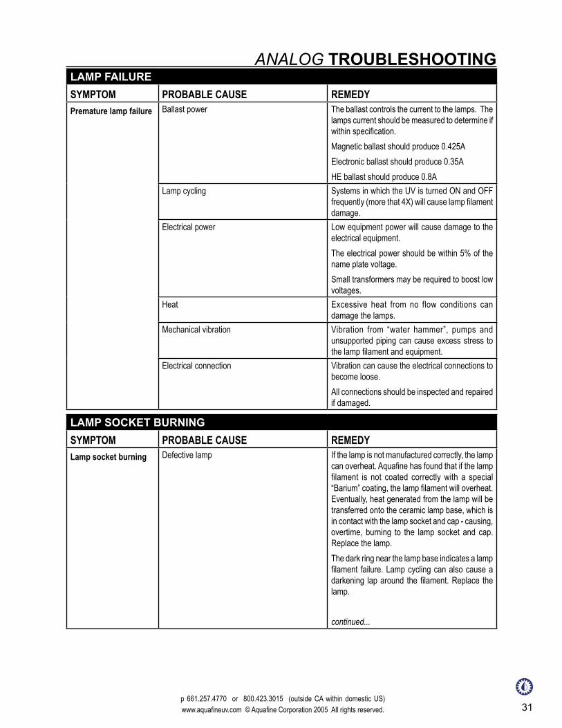
LAMP FAILURESYMPTOM PROBABLE CAUSE REMEDYPremature lamp failure Leaking/Water in Quartz Sleeve If water is present in the quartz sleeve, repair the
leak immediately. Water can cause the lamp socket to arc, corrosion on the lamp pins, burning of the lamp sockets and damage to the ballast and LED components.
p 661.257.4770 or 800.423.3015 (outside CA within domestic US) www.aquafineuv.com © Aquafine Corporation 2005 All rights reserved. 31
ANALOG TROUBLESHOOTINGLAMP FAILURESYMPTOM PROBABLE CAUSE REMEDYPremature lamp failure Ballast power The ballast controls the current to the lamps. The
lamps current should be measured to determine if within specification. Magnetic ballast should produce 0.425AElectronic ballast should produce 0.35A HE ballast should produce 0.8A
Lamp cycling Systems in which the UV is turned ON and OFF frequently (more that 4X) will cause lamp filament damage.
Electrical power Low equipment power will cause damage to the electrical equipment. The electrical power should be within 5% of the name plate voltage. Small transformers may be required to boost low voltages.
Heat Excessive heat from no flow conditions can damage the lamps.
Mechanical vibration Vibration from “water hammer”, pumps and unsupported piping can cause excess stress to the lamp filament and equipment.
Electrical connection Vibration can cause the electrical connections to become loose. All connections should be inspected and repaired if damaged.
LAMP SOCKET BURNINGSYMPTOM PROBABLE CAUSE REMEDYLamp socket burning Defective lamp If the lamp is not manufactured correctly, the lamp
can overheat. Aquafine has found that if the lamp filament is not coated correctly with a special “Barium” coating, the lamp filament will overheat. Eventually, heat generated from the lamp will be transferred onto the ceramic lamp base, which is in contact with the lamp socket and cap - causing, overtime, burning to the lamp socket and cap. Replace the lamp.The dark ring near the lamp base indicates a lamp filament failure. Lamp cycling can also cause a darkening lap around the filament. Replace the lamp.
continued...

32This document is not to be copied, electronically stored or reproduced without written permission from Aquafine Corporation.
TROUBLESHOOTING ANALOG
UV SENSORSYMPTOM PROBABLE CAUSE REMEDYUV Sensor declining Defective component As UV lamps age, the lamps solarize. After a
normal operation of lamp life, the lamps should be replaced. Please note that the lamps will remain lit for many hours after the recommended lamp life, but the UV output will decline.
Quartz sleeves fouling In raw water applications (non RO/DI), minerals or debris will attach to the quartz sleeves. The material will block the transmission of the UV energy into the water. The quartz sleeves must be replaced or cleaned. CIP does not always properly clean the quartz sleeves.
Water quality Any changes in the water transmission or quality will cause the sensor reading to change. In some applications where the water is blended, the transmission properties can change.
LAMP SOCKET BURNINGSYMPTOM PROBABLE CAUSE REMEDYLamp socket burning Lamp Socket A defective lamp socket can cause a lamp socket
to fail and burn. Within the lamp socket assembly are metallic receptacles. If the receptacles do not make proper contact with the lamp pins, a high resistance short will occur, eventually resulting in heat build up in the interior of the socket. Replace lamp socket.Corrosion of the lamp pins and socket pins can cause a high resistance short. Replace lamp and lamp socket.
Lamp connection The UV lamps operate under high voltage. If the lamp pins and socket are not properly engaged, the connection can create an electrical arc, eventually generating enough heat to melt the components. Replace lamp and lamp socket and assure connection is properly secure.
Ballasts The ballast controls the electrical power to the lamps. If there is a problem with the ballast, which results in lamp flickering or over-powering, damage can be done to the lamp connector assembly. Replace ballast.
System restart time delay has been set to 30 minutes.
Check the SW-7-1 switch - - CLOSED = 3 minutes, OPEN = 5 seconds.
p 661.257.4770 or 800.423.3015 (outside CA within domestic US) www.aquafineuv.com © Aquafine Corporation 2005 All rights reserved. 33
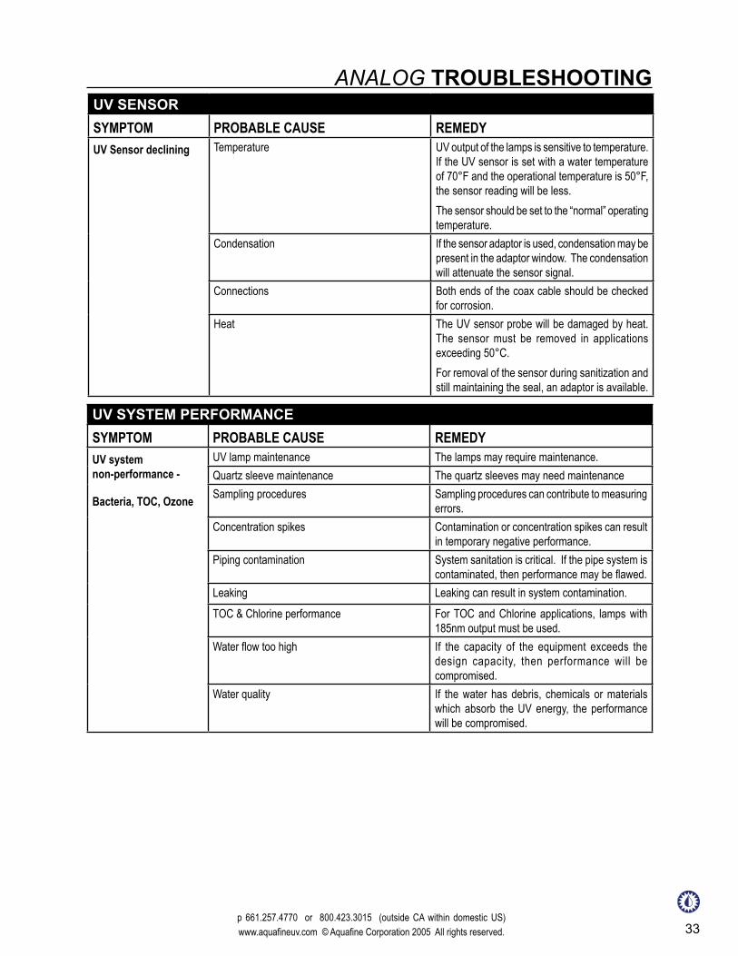
UV SENSORSYMPTOM PROBABLE CAUSE REMEDYUV Sensor declining Temperature UV output of the lamps is sensitive to temperature.
If the UV sensor is set with a water temperature of 70°F and the operational temperature is 50°F, the sensor reading will be less. The sensor should be set to the “normal” operating temperature.
Condensation If the sensor adaptor is used, condensation may be present in the adaptor window. The condensation will attenuate the sensor signal.
Connections Both ends of the coax cable should be checked for corrosion.
Heat The UV sensor probe will be damaged by heat. The sensor must be removed in applications exceeding 50°C. For removal of the sensor during sanitization and still maintaining the seal, an adaptor is available.
UV SYSTEM PERFORMANCESYMPTOM PROBABLE CAUSE REMEDYUV system non-performance -
Bacteria, TOC, Ozone
UV lamp maintenance The lamps may require maintenance.Quartz sleeve maintenance The quartz sleeves may need maintenanceSampling procedures Sampling procedures can contribute to measuring
errors.Concentration spikes Contamination or concentration spikes can result
in temporary negative performance.Piping contamination System sanitation is critical. If the pipe system is
contaminated, then performance may be flawed.Leaking Leaking can result in system contamination.TOC & Chlorine performance For TOC and Chlorine applications, lamps with
185nm output must be used.Water flow too high If the capacity of the equipment exceeds the
design capacity, then performance will be compromised.
Water quality If the water has debris, chemicals or materials which absorb the UV energy, the performance will be compromised.
ANALOG TROUBLESHOOTING

34This document is not to be copied, electronically stored or reproduced without written permission from Aquafine Corporation.
UV & TEMPERATURE MONITORING SYSTEM NOT OPERATINGSYMPTOM PROBABLE CAUSE REMEDYNo Display Check Power Check the supply voltage to the unit.
Voltage Selector Switch The Voltage Selector Switch on the printed on the Printed Circuit Board (PCB) must be selected to the supply voltage.
Fuse There is a fuse on the PCB. Check the fuse to determine if there is damage.
UV lamps will not turn ON
Power to the Unit Main power to the unit should be checked.GFI Some UV units are equipped with a GFI. Resetting
the GFI will restore power to the unit.Blown fuse/circuit breaker Check main fuse or circuit breaker.
A complete inspection to determine the cause of failure should be completed.
Defective Temperature probe Temperature indicates OP or SH. The system will operate for 30 minutes with SH, OP will then shut down.
System restart time delay has been set to 30 minutes.
Check the SW-7-1 switch - - CLOSED = 3 minutes, OPEN = 5 seconds.
TROUBLESHOOTING ANALOG
HIGH TEMPERATURE LED IS ILLUMINATEDSYMPTOM PROBABLE CAUSE REMEDYHigh Temperature LED in ON
Water temperature is above Set Point If the water temperature is above the Set Point, the high temperature LED will illuminate. Press the Temperature display button.
Loose connection on cable A loose or disconnected connection can result in a false reading. There are five connections. The terminal connections are color coded to the corresponding wires.
No supply voltage to the detector Measure the supply voltage to the detector. The voltage between the RED wire and the BLACK wire should be 5V DC. If there is no voltage, the PCB may be defective.
Detec tor temperature s igna l is out o f specification.
Measure the voltage between the WHITE wire and the BROWN wire. The voltage should be 0-.25V DC. The voltage will depend upon the water temperature. The voltage should be 20mV/de°F, if the water is 70°F, then the corresponding voltage would be 0.7.
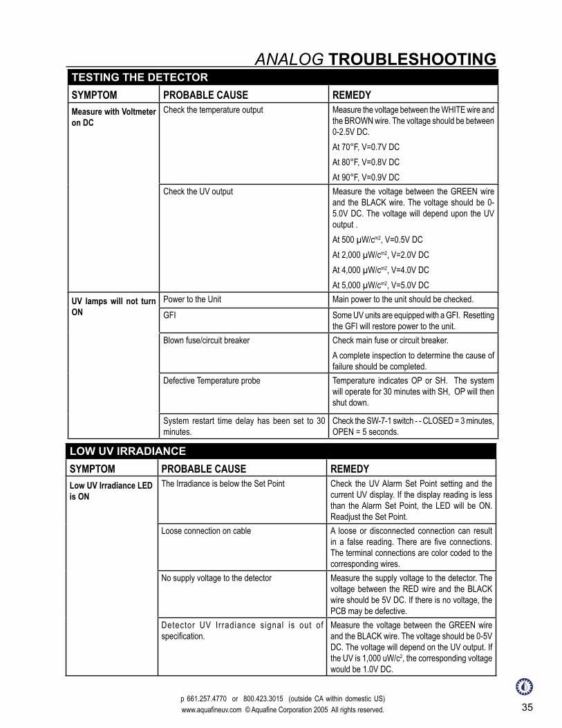
TESTING THE DETECTORSYMPTOM PROBABLE CAUSE REMEDYMeasure with Voltmeter on DC
Supply voltage to the detector Measure the supply voltage to the detector. The voltage should be between the RED wire and BLACK wire should be 5V DC. If there is no voltage, the PCB may be defective.
p 661.257.4770 or 800.423.3015 (outside CA within domestic US) www.aquafineuv.com © Aquafine Corporation 2005 All rights reserved. 35
LOW UV IRRADIANCESYMPTOM PROBABLE CAUSE REMEDYLow UV Irradiance LED is ON
The Irradiance is below the Set Point Check the UV Alarm Set Point setting and the current UV display. If the display reading is less than the Alarm Set Point, the LED will be ON. Readjust the Set Point.
Loose connection on cable A loose or disconnected connection can result in a false reading. There are five connections. The terminal connections are color coded to the corresponding wires.
No supply voltage to the detector Measure the supply voltage to the detector. The voltage between the RED wire and the BLACK wire should be 5V DC. If there is no voltage, the PCB may be defective.
Detector UV Irradiance signal is out of specification.
Measure the voltage between the GREEN wire and the BLACK wire. The voltage should be 0-5V DC. The voltage will depend on the UV output. If the UV is 1,000 uW/c2, the corresponding voltage would be 1.0V DC.
ANALOG TROUBLESHOOTINGTESTING THE DETECTORSYMPTOM PROBABLE CAUSE REMEDYMeasure with Voltmeter on DC
Check the temperature output Measure the voltage between the WHITE wire and the BROWN wire. The voltage should be between 0-2.5V DC. At 70°F, V=0.7V DCAt 80°F, V=0.8V DCAt 90°F, V=0.9V DC
Check the UV output Measure the voltage between the GREEN wire and the BLACK wire. The voltage should be 0-5.0V DC. The voltage will depend upon the UV output .At 500 µW/cm2, V=0.5V DCAt 2,000 µW/cm2, V=2.0V DCAt 4,000 µW/cm2, V=4.0V DCAt 5,000 µW/cm2, V=5.0V DC
UV lamps will not turn ON
Power to the Unit Main power to the unit should be checked.GFI Some UV units are equipped with a GFI. Resetting
the GFI will restore power to the unit.Blown fuse/circuit breaker Check main fuse or circuit breaker.
A complete inspection to determine the cause of failure should be completed.
Defective Temperature probe Temperature indicates OP or SH. The system will operate for 30 minutes with SH, OP will then shut down.
System restart time delay has been set to 30 minutes.
Check the SW-7-1 switch - - CLOSED = 3 minutes, OPEN = 5 seconds.

36This document is not to be copied, electronically stored or reproduced without written permission from Aquafine Corporation.

p 661.257.4770 or 800.423.3015 (within domestic U.S.A. and Canada) www.aquafineuv.com © Aquafine Corporation 2009. All rights reserved. 37
BLUE SCREENSYMPTOM PROBABLE CAUSE REMEDYScreen is flashing Blue The Irradiance is below the Set Point Check the UV Alarm Set Point setting and the
current UV display. If the display reading is less than the Alarm Set Point, the screen will flash BLUE. Readjust the Set Point.
Loose connection on cable A loose or disconnected connection can result in a false reading. There are five connections. The terminal connections are color coded to the corresponding wires.
No supply voltage to the detector Measure the supply voltage to the detector. The voltage between the RED wire and the BLACK wire should be 5V DC. If there is no voltage, the PCB may be defective.
Detector UV Irradiance signal is out of specification.
Measure the voltage between the GREEN wire and the BLACK wire. The voltage should be 0-5V DC. The voltage will depend on the UV output. If the UV is 1,000 uW/c2, the corresponding voltage would be 1.0V DC.
UV & TEMP. MONIT. SYSTEM TROUBLESHOOTINGRED SCREENSYMPTOM PROBABLE CAUSE REMEDYScreen is flashing RED Water temperature is above Set Point If the water temperature is above the Set Point,
the screen will flash RED. Loose connection on cable A loose or disconnected connection can result
in a false reading. There are five connections. The terminal connections are color coded to the corresponding wires.
No supply voltage to the detector Measure the supply voltage to the detector. The voltage between the RED wire and the BLACK wire should be 5V DC. If there is no voltage, the PCB may be defective.
Detector temperature signal is out of specification.
Measure the voltage between the WHITE wire and the BROWN wire. The voltage should be 0-.25V DC. The voltage will depend upon the water temperature. The voltage should be 20mV/de °F, if the water is 70°F, then the corresponding voltage would be 0.7.
TESTING THE DETECTORSYMPTOM PROBABLE CAUSE REMEDYMeasure with Voltmeter on DC
Supply voltage to the detector Measure the supply voltage to the detector. The voltage should be between the RED wire and BLACK wire should be 5V DC. If there is no voltage, the PCB may be defective.
continued...

38This document is not to be copied, electronically stored or reproduced without written permission from Aquafine Corporation.
TESTING THE DETECTORSYMPTOM PROBABLE CAUSE REMEDYMeasure with Voltmeter on DC
Check the temperature output Measure the voltage between the WHITE wire and the BROWN wire. The voltage should be between 0-2.5V DC. At 70F°, V=0.7V DCAt 80F°, V=0.8V DCAt 90F°, V=0.9V DC
Check the UV output Measure the voltage between the GREEN wire and the BLACK wire. The voltage should be 0-5.0V DC. The voltage will depend upon the UV output .At 500µW/cm2, V=0.5V DCAt 2,000µW/cm2, V=2.0V DCAt 4,000µW/cm2, V=4.0V DCAt 5,000µW/cm2, V=5.0V DC
TROUBLESHOOTING UV & TEMP. MONIT. SYSTEM
WATER TEMP. ALARMSYMPTOM PROBABLE CAUSE REMEDYUnit does not shut OFF when water temp. is above 120°F
Temp. Alarm point set to 170° F Reset Temp. Alarm SET POINT to 120° FLost Temp. Signal Check cable connection between detector and
Monitoring Station.Temp. Alarm Set Point is OFF Reset Temp. Alarm Set Point to 120° F
UV ALARMSYMPTOM PROBABLE CAUSE REMEDYUV Alarm does not operate
UV Alarm Set Point set incorrectly Reset Alarm Set Point to 0-100%UV Alarm Point is OFF Reset UV Alarm Set Point to ON (0-100%)

p 661.257.4770 or 800.423.3015 (within domestic U.S.A. and Canada) www.aquafineuv.com © Aquafine Corporation 2010. All rights reserved. 39
WARRANTYThe following installation and operating conditions are considered hazardous and damaging to the equipment,compromising the ability of the Aquafine unit to perform as intended.
1. Failure to supply the correct voltage and frequency as indicated on the nameplate decal.
2. Failure to comply Aquafine electrical drawings and with local electrical codes.
3. Failure to properly ground the unit.
4. Failure to eliminate excessive vibration, piping, movement, or “water hammer”.
5. Failure to exercise caution in the handling of the sensitive and delicate components (such as lamps, quartz sleeves, electronic boards, etc.) during installation and/or maintenance procedures.
6. Failure to avoid excessive stops and starts. Not more than three (3) “ON/OFF” cycles per 24 hours of operation.
7. Operation of visibly damaged equipment.
8. Failure to avoid undue overhead piping stress, which can result in structural damage to the UV unit. Limit the load to 25 lbs (11.3 kg), for 2” & 3”, 50 lbs (23 kg), for 4” and 75 lbs (34 kg), for 6” or above. Torsion loads or side loading of the risers should be eliminated.
9. Use the components other than those provided or authorized by Aquafine.
10. Failure to correct overhead piping connection leaks or compression nut seal leaks which result in damage to the electrical components.
11. Allowing operating water temperature to exceed 120°F.
12. Operating the units without water flow.
Any of the following conditions will void the equipment warranty:
NOTE: To register your UV system for warranty, go online to www.aquafineuv.com
REMEMBER, ALWAYS USING GENUINE AQUAFINE PARTS KEEPS YOUR WARRANTY, UL, CE & NSF CERTIFICATIONS VALID.
Please see Aquafine’s official warranty on the following page.

40This document is not to be copied, electronically stored or reproduced without written permission from Aquafine Corporation.

p 661.257.4770 or 800.423.3015 (within domestic U.S.A. and Canada) www.aquafineuv.com © Aquafine Corporation 2009. All rights reserved. 41
AQUAFINE EQUIPMENT WARRANTYThe following terms and conditions will govern the equipment warranty provided by Aquafine Corporation Inc. to the Owner/Operator:
Aquafine Corporation (“Aquafine”) warrants to the Owner/Operator noted above (the “Customer”) that if within 12 months from equipment start-up or 18 months from the date of delivery, whichever comes first, equipment manufactured by Aquafine (the “Equipment”) will be free from defects in material and workmanship and will function in accordance with the specifications agreed to by Aquafine for the Equipment.This warranty shall not apply to any failure or defect which results from the Equipment not being operated and maintained in strict accordance with instructions specified in the Operation and Maintenance manual or which results from mishandling, misuse, neglect, improper storage, improper operation of the Equipment with other equipment furnished by the Customer or other third parties or defects in designs or specifications furnished by or on behalf of the Customer by a person other than Aquafine. In addition, this warranty shall not apply to Equipment that has been altered or repaired after start-up by anyone except: (a) authorized representatives of Aquafine, or (b) Customer acting under specific instructions from Aquafine.Customer must notify Aquafine in writing within 5 days of the date of any Equipment failure. This notification shall include a description of the problem, a copy of the operator’s log, a copy of the Customer’s maintenance record and any analytical results detailing the problem. If Customer has not maintained the operator’s log and maintenance record in the manner directed in the Operation and Maintenance manual, or does not notify Aquafine of the problem as specified above, this warranty may, in Aquafine’s discretion, be invalid.Customer will fully cooperate with Aquafine, in the manner requested by Aquafine, in attempting to diagnose and resolve the problem by way of telephone support. If the problem can be diagnosed by telephone support and a replacement part is required Aquafine will either, at Aquafine’s expense, ship a repaired, reworked or new part to the Customer who will install such part as directed by Aquafine or will direct Customer to acquire, at Aquafine’s expense, such part from a third party and then install such part as directed by Aquafine.In the event that Aquafine determines that the problem cannot be resolved by way of telephone support and/or shipment by Aquafine, or acquisition by the Customer, of a replacement part for installation by the Customer, Aquafine will send one or more persons to make an on site inspection of the problem. If an on site visit is made, Aquafine personnel will evaluate the problem and repair or replace any Equipment determined to be in breach of this warranty. If the problem is not attributable to a breach of this warranty, Aquafine reserves the right to invoice the Customer for this service.Equipment components manufactured by third parties but furnished to Customer by Aquafine are warranted by the original manufacturer, only to the extent of the original manufacturer’s warranty, and are not covered by the above warranty.This warranty is the exclusive remedy for all claims based on a failure of or defects in the Equipment, whether the claim is based on contract (including fundamental breach), tort (including negligence), strict liability or otherwise. This warranty is in lieu of all other warranties whether written, oral, implied or statutory. Without limitation, no warranty of merchantability or fitness for a particular purpose shall apply to the Equipment.Aquafine does not assume any liability for personal injury or property damage caused by use or misuse of the Equipment. Aquafine shall not in any event be liable for special, incidental, indirect or consequential damages including, without limitation, lost profits, lost business opportunities, lost revenue or loss or depreciation of goodwill, even if it has been advised of the possibility thereof. Aquafine’s liability shall, in all instances, be limited to repair or replacement of Equipment in breach of this warranty and shall not exceed the cost of such repair or replacement. This liability with respect to repair or replacement will terminate upon the expiration date of this warranty.In addition to the foregoing, in no event shall Aquafine’s liability relating to the Equipment, or the agreement between Aquafine and the Customer relating to the Equipment, exceed that portion of the purchase price for the Equipment which is actually paid to Aquafine.

42This document is not to be copied, electronically stored or reproduced without written permission from Aquafine Corporation.


© Aquafine Corporat ion 2010. All rights reserved. This document is not to be copied, electronically stored or reproduced without written permission from Aquafine Corporation.
Pure Quality
The principles of customer dedication, product quality and reliability are essential in ensuring the purity of water. With innovation and advanced expertise, Aquafine
continues to be the world leader in UV water treatment systems for Industrial & Commercial applications.
North America & International Europe29010 Ave Paine, Valencia, CA 91355 Ramskamp 77-85 D-25337 Elmshorn, GermanyP 661 257 4770 F 661 257 2489 P +49 4121 57806 13 F+49 4121 57806 [email protected] www.aquafineuv.com [email protected] www.aquafineuv.com
Aquafine is an ISO 9001:2008 certified company.