Embed Size (px)
Citation preview
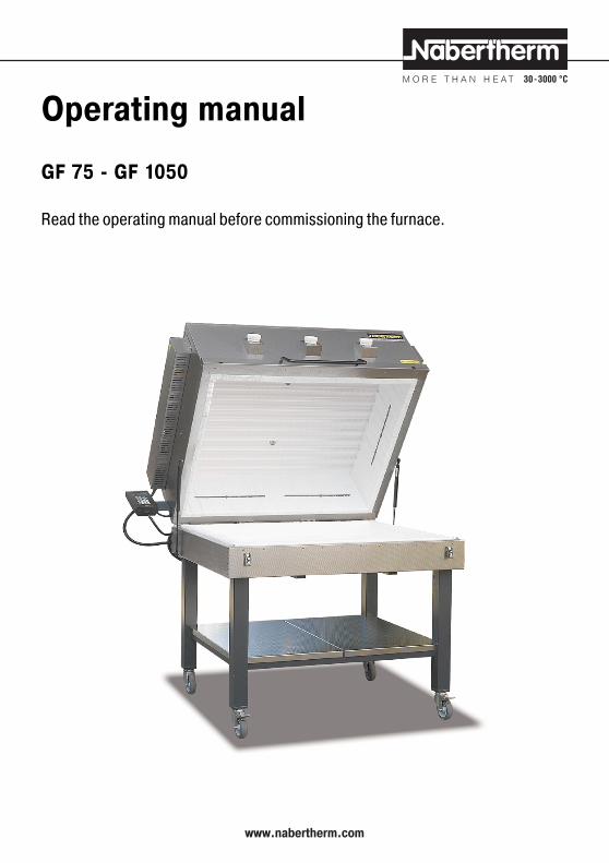
Operating manual
GF 75 - GF 1050
Read the operating manual before commissioning the furnace.
www.nabertherm.com

2
General information ........................................ 2Safety .......................................................... 3Mounting the furnace ..................................... 3Commissioning the furnace ............................. 4Maintenance/errors ....................................... 5Troubleshooting ............................................ 6Repair instructions ......................................... 6Circuit diagrams ............................................. 9Declaration of conformity .............................. 14Notes ......................................................... 15
This furnace is an electrically heated top hat furnacefor fusing glass. Other applications must be agreedupon in writing with Nabertherm.
The multi-layer heat insulation is of exceptionally highquality and energy-saving.
The furnace is equipped with a Controller thatprovides extensive protection against incorrectoperation. A long-life NiCr-Ni thermocouple is usedfor measuring and controlling the furnace chambertemperature.
Technical specifications:Furnace ratings: see the ratings sign on the
left side of the furnaceDimensionsand weights: see tableProtection class: 1Enclosure ratingof the furnace: IP 10
Thermal safety according to EN 605192-2,1993:• without safety controller: Class 0, in case of error
no protection for furnace or material.• with safety controller: Class 2, in case of error
furnace and material are protected
Ambient conditions:Temperature: 5 - 40 °CHumidity: max. 95%, non-
condensing
General information
Contents
1without substructure*Outer dimensions
Model
GF 75/..GF 190GF 240GF 380GF 420GF 520GF 600GF 920GF 1050
Width*mm850
13401450165021001650245025502750
Depth*mm750910
1200140012501550140015501600
Height*
mm5701
6601
6601
135012701350127013501350
Weightkg701
1651
2051
350350350540670780
3
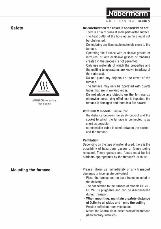
Be careful when the cover is opened when hot• There is a risk of burns at some parts of the surface.• The heat outlet of the housing surface must not
be obstructed.• Do not bring any flammable materials close to the
furnace.• Operating the furnace with explosive gasses or
mixtures, or with explosive gasses or mixturescreated in the process is not permitted.
• Only use materials of which the properties andthe melting temperatures are known (marking ofthe materials).
• Do not place any objects on the cover of thefurnace.
• The furnace may only be operated with quartztubes that are in working order.
• Do not place any objects on the furnace asotherwise the carrying-off of heat is impeded, thefurnace is damaged and there is a fire hazard.
With 230 V models: Ensure that:• the distance between the safety cut-out and the
socket to which the furnace is connected is asshort as possible.
• no extension cable is used between the socketand the furnace.
Ventilation:Depending on the type of material used, there is thepossibility of hazardous gasses or fumes beingreleased. These gasses and fumes must be ledoutdoors appropriately by the furnace’s exhaust.
Please inform us immediately of any transportdamages or incomplete deliveries!• Place the furnace on the base frame included in
the delivery.• The connection to the furnace of models GF 75 -
GF 240 is pluggable and can be disconnectedduring transport.
• When mounting, maintain a safety distanceof 0.5m to all sides and 1m to the ceiling.
• Provide sufficient room ventilation.• Mount the Controller at the left side of the furnace
(if not factory-installed).
ATTENTION! Hot surface- Risk of burns -
Mounting the furnace
Safety

4
• Connect the plug of the Controller (C 30) to thesocket of the switchgear.
• Connect the furnace’s plug into thecorresponding power socket (do not use anextension cable).
During the baking process hazardous gasses andfumes may be released. Therefore it is necessary tolead the „exhaust fumes“ from the ventilationopenings outdoors in an appropriate way.
The furnace must be fired once to dry the insulationand to attain an oxide protection layer on theresistance wire coil, please see also the Controllerinstructions. This may cause an unpleasant smell.
• Close the cover and secure it with the lock• Heat up the furnace to 500 °C in 6 hours, heat up
to 850 °C at full power, maintain this temperaturefor 15 minutes, let furnace cool down on its own.To enter the temperatures and times, please readthe instructions for the Controller.
The heating elements can break easily when cold.Take special care of this when charging the furnacewith products and removing them, and also whencleaning the furnace.
During the baking process the cover may only beopened briefly.
While baking gasses, fumes and humidity arereleased which may result in discolouration orcorrosion of the furnace.
Our top hat furnaces should not be used asdrying ovens.
The sight hole/fresh air openings can be opened toshorten the cooling phase after baking.
Commissioning the furnace

5
Regularly clean the inside of the furnace with avacuum cleaner. Attention: While doing this do nottouch the heating elements to avoid damaging them.
In the case of commercial use:Please observe the safety regulations applicableto your country.
According to a regulation of the Germanemployer’s liability insurance association thefurnace must be checked by a qualifiedelectrician at specified intervals.
If the heating elements are damaged the furnacemust be switched off immediately. Damaged tubesare to be replaced before commissioning.
The furnace switchgear * is equipped with silentsemiconductor relays. Semiconductor relays areresistant to wear.* The switchgear of model GF 1050 is equipped withcontactors. The heating contactor is a expendablepart. Depending on the local conditions and theheavy duty, the contactor must be checked in regularintervals and excanched latest after 1 year.
Use the error search list (Troubleshooting), the repairinstructions and the circuit diagram (see the followingpages) to identify and eliminate errors.
Only a qualified electrician may carry out workon the electrical system.
Cracks in the insulation:The insulation of the furnace consists of very high-quality fire-resistant material. As a result of heatexpansion, cracks appear in the insulation after afew heating cycles. However, these cracks have noinfluence on the function or quality of the furnace.
Maintenance/errors
6
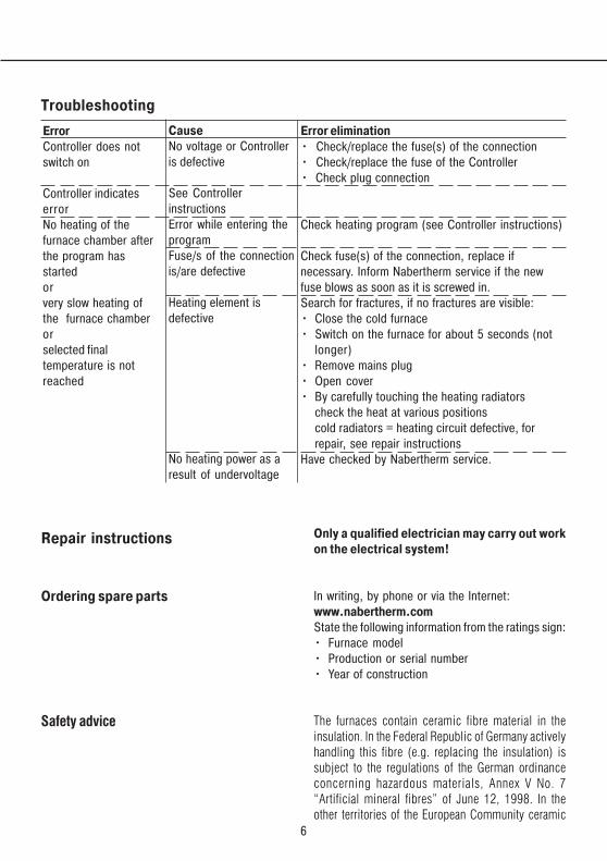
Troubleshooting
ErrorController does notswitch on
Controller indicateserrorNo heating of thefurnace chamber afterthe program hasstartedorvery slow heating ofthe furnace chamberorselected finaltemperature is notreached
Error elimination• Check/replace the fuse(s) of the connection• Check/replace the fuse of the Controller• Check plug connection
Check heating program (see Controller instructions)
Check fuse(s) of the connection, replace ifnecessary. Inform Nabertherm service if the newfuse blows as soon as it is screwed in.Search for fractures, if no fractures are visible:• Close the cold furnace• Switch on the furnace for about 5 seconds (not
longer)• Remove mains plug• Open cover• By carefully touching the heating radiators
check the heat at various positionscold radiators = heating circuit defective, forrepair, see repair instructions
Have checked by Nabertherm service.
CauseNo voltage or Controlleris defective
See ControllerinstructionsError while entering theprogramFuse/s of the connectionis/are defective
Heating element isdefective
No heating power as aresult of undervoltage
Repair instructions
Ordering spare parts
Safety advice
Only a qualified electrician may carry out workon the electrical system!
In writing, by phone or via the Internet:www.nabertherm.comState the following information from the ratings sign:• Furnace model• Production or serial number• Year of construction
The furnaces contain ceramic fibre material in theinsulation. In the Federal Republic of Germany activelyhandling this fibre (e.g. replacing the insulation) issubject to the regulations of the German ordinanceconcerning hazardous materials, Annex V No. 7“Artificial mineral fibres” of June 12, 1998. In theother territories of the European Community ceramic
7
fibres are classified by the Directive 98/69/EC of theCommission of December 5, 1997 as follows: CARC.Cat. 2; R 49; Xi R 38. Working on the fibre insulationmust therefore be executed in such a way that the fibredusts released are kept at a minimum.We recommend wearing a breathing mask (P2 or higher),gloves as well as a protective suit.
Removal• Remove mains plug• Remove protective cover of the electrical terminals
on the side walls of the cover• Loosen and remove terminals at the ends of the
heating coil• Remove wall ducts• Pull out heating coil
Insertion• If cleaning is not possible, insert new wall ducts
or quartz tubes.• Install the heating coil in the tubes, push
connection ends through the holes.• Insert the wall ducts from the outside.• Create the electrical connections with new
terminals:Hold bottom part of terminals with pliers, tightenthe screw.
• Cut off any excess twisted wire ends.• Mount the protective cover of the electrical
terminals.
If the insulation of the furnace chamber shows seriousdamages, it must be repaired.
• Remove mains plug• Remove protective cover of the electrical terminals
on the side wall of the furnace• Remove the safety screw of the thermocouple• Remove the cable ends of the thermocouple• Screw out defective thermocouple and insert new
one• Connect new thermocouple (green cable to „+“,
white to „-“)
Replacing the heating coil
Repairing the insulation
Exchanging the thermocouple
8
• Attach thermocouple to furnace housing withsafety screw
• Mount protective cover• Check function
Ensure that:• the terminals are fastened tightly!• the anti-interference capacitor is connected to
the contactor coil!
Exchanging the contactor
9
1L1L
2T2T
A1+A1+ A2-A2-
-X9:1
-X9:2
-X11:1
-X11:2
-X12b:1
-F34
S1
-T36-V35
-K47A1
A2
-V37
-X12b:2
-X12a:2-X12a:1
-X2
L2
L2 L2’
L1
L1 L1’L1
L3 N
L3 L3’
2
1
4
3
6
5
-X21:1 + 12V
-X21:2 - 12V
X4:1/2 X4:3/4 X4:5/6
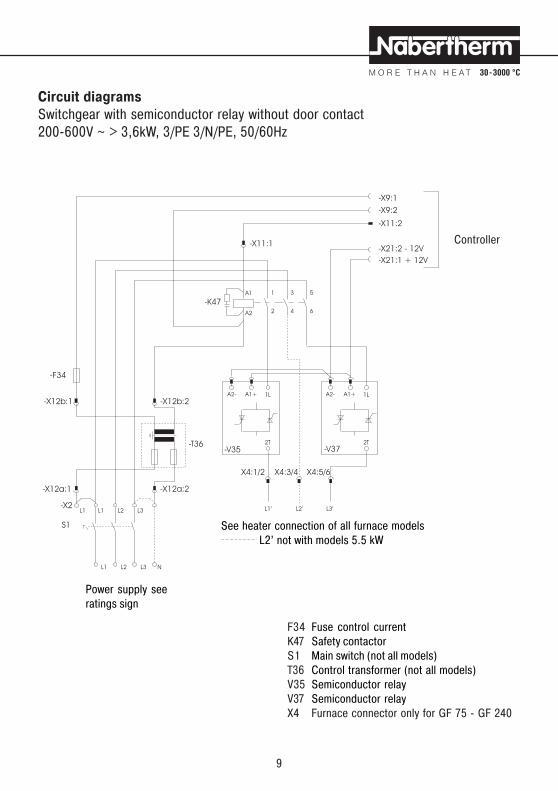
Circuit diagramsSwitchgear with semiconductor relay without door contact200-600V ~ > 3,6kW, 3/PE 3/N/PE, 50/60Hz
Controller
F34 Fuse control currentK47 Safety contactorS1 Main switch (not all models)T36 Control transformer (not all models)V35 Semiconductor relayV37 Semiconductor relayX4 Furnace connector only for GF 75 - GF 240
Power supply seeratings sign
See heater connection of all furnace models L2’ not with models 5.5 kW
10
1L 1L 1L
2T 2T 2T
A1+ A1+ A1+A2- A2- A2-
-X9:1
-X9:2
-X11:1
-X11:2
-K47
-K47.1
A1
A1
A2
A2
L1
L1 L1 L1 L2/N L2/N L2/N
L2 (N)
2
1
4
3
6
5
2
1
4
3
6
5
L1.1’
L2.1’
(N.1’)
L2.2’
(N.2’)
L2.3’
(N.3’)
L1.2’ L1.3’
-V35 -V37 -V38
-X2
-X21:1 + 12V
-X21:2 - 12V
-X12b:1
-F34
-T36
-X12b:2
-X12a:2-X12a:1
X4:1/2
X4:1/2
X4:3/4
X4:3/4
X4:5/6
X4:5/6
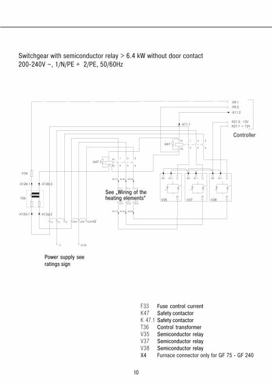
Switchgear with semiconductor relay > 6.4 kW without door contact200-240V ~, 1/N/PE + 2/PE, 50/60Hz
F33 Fuse control currentK47 Safety contactorK 47.1 Safety contactorT36 Control transformerV35 Semiconductor relayV37 Semiconductor relayV38 Semiconductor relayX4 Furnace connector only for GF 75 - GF 240
Controller
Power supply seeratings sign
See „Wiring of theheating elements“

11
1L
2T
A1+A2-
-X9:1
-X9:2
-X11:2
-X12b:1
-F34
-T36-V35
-K47A1
A2
-X12b:2
-X12a:2-X12a:1
-X2 L2’(N’)
L1
L1 L1’
L2(N)
2
1
4
3
6
5
-X21:1 + 12V
-X21:2 - 12V
X4:1/2 X4:5/6
-X11:1
Switchgear with semiconductor relay without door contact200-240V ~ < 5,5kW, 1/N/PE 2/PE, 50/60Hz
F34 Fuse control currentK47 Safety contactorS1 Main switch (not all models)T36 Control transformer (not all models)V35 Semiconductor relayV37 Semiconductor relayX4 Furnace connector only for GF 75 - GF 240
Controller
Power supply seeratings sign
See „Wiring of theheating elements“
12
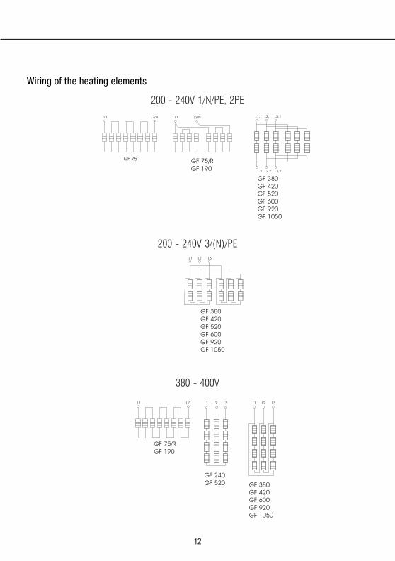
GF 75/R
GF 190
GF 75/R
GF 190
GF 75
GF 380
GF 420
GF 520
GF 600
GF 920
GF 1050
GF 380
GF 420
GF 520
GF 600
GF 920
GF 1050
GF 380
GF 420
GF 600
GF 920
GF 1050
L1L1
L1L1 L2/N
L2L2
L2/N
L3L1 L2 L3
GF 240
GF 520
L1
L1.1
L1.2
L2
L2.1
L2.2
L3
L3.1
L3.2
200 - 240V 1/N/PE, 2PE
200 - 240V 3/(N)/PE
Wiring of the heating elements
380 - 400V
13
X9.1
X9.1
X11.2X3.6
X3.4
X3.5
X3.7 V37/37:A2
V37/37:A1X3.1
X3.3 X4:12
X3.2 X4:11
L1
N
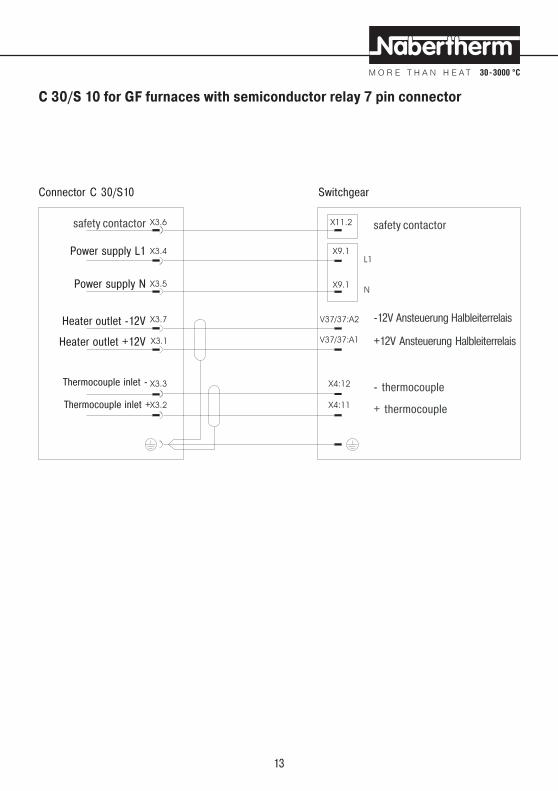
Switchgear
safety contactor
-12V Ansteuerung Halbleiterrelais
+12V Ansteuerung Halbleiterrelais
- thermocouple
+ thermocouple
C 30/S 10 for GF furnaces with semiconductor relay 7 pin connector
Connector C 30/S10
safety contactor
Power supply L1
Power supply N
Heater outlet -12V
Heater outlet +12V
Thermocouple inlet -
Thermocouple inlet +

14
Declarations of conformityfor furnaces with Nabertherm switchgear including Controller
EC – DECLARATION OF CONFORMITYaccording to EC Low-Voltage Directive No. 73/23/EC modified through 93/68/EC
and EMC Directive 89/336/EC
Nabertherm GmbH, Bahnhofstr. 20, 28865 Lilienthal
Electrically heated fusing furnace
Model GF 75 GF 75R GF 190 GF 240 GF 380
Tmax 950 °C 950 °C 950 °C 950 °C 950 °C
Nominal voltage 230 V 1/N/PE ~ 400 V 2/N/PE ~ 400 V 2/N/PE ~ 400 V3/N/PE ~ 400 V3/N/PE ~
Power rating 3,6 kW 5,5 kW 6,4 kW 11 kW 15 kW
Model GF 420 GF 520 GF 600 GF 920 GF 1050
Tmax 950 °C 950 °C 950 °C 950 °C 950 °C
Nominal voltage 400 V3/N/PE ~ 400 V 3/N/PE ~ 400 V3/N/PE ~ 400 V3/N/PE ~ 400 V3/N/PE ~
Power rating 18 kW 15 kW 22 kW 26 kW 32 kW
For all Furnaces: Nominal frequency of 50/60 Hz
Harmonized standards/valid EC Directives:
Low-Voltage Directive: EN 60335-1 EN 60519-1EN 60519-2
EMC-Directive: EN 61000-6-1 EN 61000-6-3
Lilienthal, 30.06.2004
Thomas Adamek Gernot Fäthke

15
Notes

Reg.
no. B
1.2
2 (e
nglis
ch),
Febr
uar 2
005
Headquarters: No responsibility is accepted for the correctness of this information, we reserve the right to make technical alterations
Nabertherm GmbH • Bahnhofstr. 20 • 28865 Lilienthal/Bremen, Germany • Tel. +49 (04298) 922-0, Fax -129 • [email protected] • www.nabertherm.com