Embed Size (px)
Citation preview
Reactive Semantics for DistributedUML Activities
Frank Alexander Kraemer and Peter Herrmann
Norwegian University of Science and Technology (NTNU),Department of Telematics, N-7491 Trondheim, Norway
{kraemer, herrmann}@item.ntnu.no
Abstract. We define a reactive semantics for a subset of UML activitiesthat is suitable as precise design language for reactive software systems.These semantics identify run-to-completion steps for execution on thelevel of UML activities as so-called activity steps. We show that activitiesadhering to these semantics and a set of rules lead to event-driven andbounded specifications that can be implemented automatically by modeltransformations and executed efficiently using runtime support systems.
Key words: UML Activities, UML Semantics, Reactive Systems
1 Introduction
UML 2.0 activities essentially denote in which order certain actions have to beexecuted to accomplish some task, and are therefore suitable for a wide range ofapplications. With their revision for the second major version of the UML stan-dard [1], they were considerably enhanced with respect to supporting concurrentflows and hierarchically structured specifications. In the following, we focus onthe application of UML activities on the domain of reactive systems. This classof systems, characterized by Pnueli as ones that “maintain some interactionwith their environment” [2], is interesting, since with an increasing degree ofconnectivity of devices and the ubiquity of sensors that provide data, more andmore applications fall into this category of systems. In general, these reactiveapplications and corresponding systems are characterized as follows:
– There is a high degree of concurrency in the applications, since typically sev-eral connections are simultaneously active and events from different sourcescan occur at any time.
– These applications are event-driven, that means they execute their behavioras reactions on events such as incoming signals from other devices, userinterface interactions or updated sensor inputs.
These characteristics make the development of reactive systems quite demand-ing, especially with respect to concurrency. Achieving concurrency by processesexecuting in parallel is complicated, since synchronizations between them aredifficult to understand and error-prone. In addition, the number of processes
UML Activity
Runtime Support SystemsCommunication BusComponents
Transformation, Code Generation
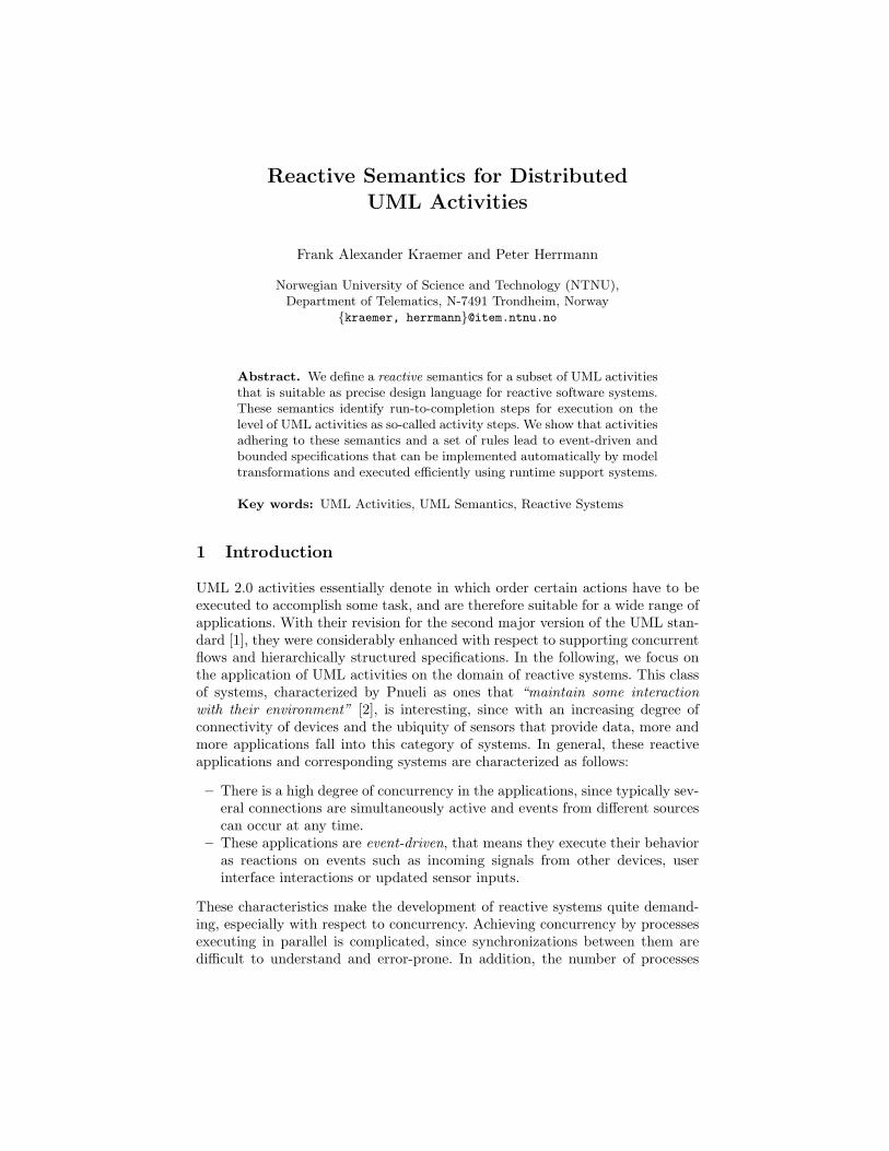
Fig. 1. Execution of components by runtime support systems
that can be executed efficiently in parallel is limited, in particular on mobile orembedded devices.
One way to deal with the complexity of concurrent executions is the introduc-tion of runtime support systems [3], illustrated in the lower part of Fig. 1. Thesesystems contain schedulers that control the execution of a component’s behaviorby dispatching events. Such events are the arrival of signals from other compo-nents, the expiration of timers, or internal signals that arise from local sensordata or interrupts. To be executable by a runtime support system, all applicationbehavior must be expressed as transitions triggered by observable events as de-fined above. Moreover, communication must be implemented so that the senderis not blocked, for instance via an asynchronous message bus. These propertiesenable an execution with run-to-completion characteristics. The execution of arun-to-completion step is not preempted, and concludes with a stable state inwhich the runtime support system waits to dispatch the next observable event.This makes it relatively easy to execute also complex and highly concurrent be-havior with very limited resources and a low number of system processes. There-fore, we are able to offer code generators different execution platforms, rangingfrom resource-constrained embedded systems on Sun SPOTs [4] to systems serv-ing large numbers of users like Telenor’s Connected Objects platform [5].
Our interest in activities is based on a number of characteristics they havethat are relevant for the development of distributed, reactive systems: In com-parison to state machines (that we have used before) they provide a high degreeof concurrency by default, since activity flows execute independently from eachother. We have also shown that activities can be grouped and abstracted in build-ing blocks [6], which leads to system designs that are built to high proportionsfrom reused solutions. Furthermore, since activities have the concept of parti-tions, they also describe collaborative behavior, and may encapsulate the behav-ior of several components that is necessary to fulfill a certain task, illustrated inFig. 1. We therefore built a tool that takes UML activities and implements themautomatically, using first a model transformation to UML components and statemachines [7] and then a code generation step.
In order to use activities for reactive applications that are to be executedon an event-driven runtime support system as described above, their semanticsneed to address several issues:
– Activities should identify the run-to-completion steps executed by the run-time support system, as well as the observable event triggering a step.

– It must be clear on which location a run-to-completion step is performed,i.e., which component is responsible for executing it.
– Activities should make communication explicit, i.e., all necessary communi-cation between components must be represented by activity flows.
One could argue, of course, that the abstraction level of activities does not needto deal with the same concepts as lower levels. For instance, non-local behaviorof activities could be allowed, and communication patterns on the level of com-ponent execution could be synthesized automatically (as done for instance byYamaguchi et al. [8]). However, we want the activities to express communicationexplicitly, for example to facilitate a security analysis as done in [9]. Further-more, we want developers working on the level of activities to be still aware ofcostly operations such as sending to encourage efficient solutions. For the samereason we think it is beneficial to be aware of run-to-completion steps, since theyform the temporal behavior of specifications.
In the following, we describe what we call reactive semantics for activities.Our intention is not to cover all details of the UML standard, but a subset ofelements necessary to describe a wide range of reactive applications. We willpresent UML activities with an example and define some syntactic constraintsin Sect. 3. Our semantics is based on run-to-completion steps, which on theactivity level we call activity steps. These are defined in Sect. 4. The execution ofactivities based on activity steps is then described in Sect. 5. Section 6 discussesproperties of activities and some additional constraints.
2 Related Work
There exists a variety of approaches that use different techniques to partiallydefine and discuss semantics of UML 2.0 activities. Conrad Bock, one of theauthors of the UML standard [1], covers the semantics of activities in a seriesof articles which informally clarify numerous semantic details. In particular, hedescribes the traverse-to-completion principle [10], according to which tokenspass only when all elements along a path accept the passing. This principleis implied by our semantics due to the definition of run-to-completion steps.Eshuis’ work on model checking activity diagrams [11] defines their semanticsby two mappings onto the model checker NuSMV, but in comparison to our worktargets workflow systems, in which an activity is executed by a central workflowsystem that coordinates the execution of actions [12]. Storrle uses ColouredPetri Nets in [13] to define semantics of some UML activity elements. In [14],Storrle and Hausmann conclude that Petri Nets are probably not suitable tocover more advanced concepts, and point out the difficulty of combining all thevarious target domains. Barros and Gomez explain the semantics of actions withseveral input and output pins by “unfolding” these elements into activities withsimpler control nodes [15]. Crane and Dingel [16] cover the detailed semantics ofsome specific UML action types, and describe in [17] a virtual machine for theirinterpretation. Engels et al. [18] define semantics of activities using DynamicMeta Modeling (DMM), which is based on graph transformations. Sarstedt and

initial accept
s:SMS
queueffinal afinaloperation
create report
merge
...
decision...
fork...
join
...
Fig. 2. Node kinds
Guttmann [19] use Abstract State Machines (ASMs) for the definitions of activitysemantics. This work treats token passing on a very detailed level, removingsome restrictions present in other approaches. To execute systems described byactivities, they propose the interpretation of models [20].
In contrast to these approaches, we explicitly apply UML activities to thedomain of reactive applications as characterized above, with an emphasis onexecution mechanisms for runtime support systems. For this case, we found thesemantics defined by the approaches mentioned above as not ideal, since they areeither too general or target for example business processes, which pose differentrequirements on communication and synchronization. Therefore, we cannot usethem as basis for the construction of executable components.
3 UML Activities
The UML standard uses simple text to explain activities, and characterizes theirsemantics as “Petri-like” [1, p. 324]. Some simple activity graphs can indeedeasily mapped to Petri Nets. The mapping of more complex elements of UMLactivities, however, turns out to be difficult, especially for termination behavior,as pointed out by others [14, 21, 12]. In the following, we will therefore describethe reactive semantics of activities based on the intuitive token flows as foundin Petri Nets, but use general state-transition systems in which also groups oftokens of several places can be removed simultaneously.
An activity is a directed graph A with a set of activity nodes VA and aset of activity edges EA. Function kindA ∈ [VA → K] assigns to each node akind, with K = {initial, merge, decision, fork, join, accept, operation, afinal,ffinal, queue}, as illustrated in Fig. 2. Nodes of kind accept model accept eventactions, which in our semantics represent either internal signal receptions ortimer expirations. Internal signals are used to represent events from lower layersof a component, such as interrupts or events from user interfaces. Nodes of kindoperation represent method calls. There are two kinds of final nodes, activityfinal nodes (afinal) that terminate an entire activity (hence removing tokensalso from other places and preempting other behaviors), and flow final nodes(ffinal) that just consume tokens to conclude a flow.
An activity has a non-empty set of partitions PA. In general, UML usespartitions to characterize commonalities among nodes. We use them strictly todenote different locations of executions. Thus, a flow crossing partition bordersimplies communication. For this communication, we assume an asynchronousmessage bus. This type of communication allows for an increased degree of con-

currency, but may introduce interleaving behavior that has to be taken care ofby corresponding synchronization. Since this behavior is tightly interleaved withapplication logic, the delay of messages must be represented in the activity dia-grams as well. For this reason, we introduce explicit queue places where activityflows cross partition borders. In Fig. 4, these are nodes q1 to q7.
Function inA ∈ [VA → 2EA ] yields for each node its incoming edges, andfunction outA ∈ [VA→2EA ] its outgoing edges. Vice versa, we refer to sourceA(e)to get the source node of an edge, and targetA(e) for its target. We assume thatonly merge and join nodes have more than one incoming edge, and only decisionand fork nodes have more than one outgoing edge. All structural constraints aresummarized by the rules in Fig. 3. Function partA ∈ [VA → PA ∪ (PA × PA)]assigns partitions to nodes, so that each queue node is mapped to a pair ofpartitions modeling the transmission of signals between components (PQ). Allother nodes are assigned to exactly one partition (PN). Rule E1 ensures thatedges do not have the same node as source and target, and P1 ensures thatthere are no edges between two queues. These cases do not model useful behavior.Rules P2 to P4 ensure that edges do not cross partition borders without a queue
IN1v∈VA kindA(v) ∈ {initial}
|inA(v)| = 0IN2
v∈VA kindA(v) ∈ {merge, join}|inA(v)| ≥ 2
IN3
v∈VA kindA(v) ∈ {decision, fork,
accept, operation, ffinal, afinal, queue}|inA(v)| = 1
OUT1
v∈VA kindA(v) ∈ {initial,
merge, join, accept, operation}|outA(v)| = 1
OUT2
v∈VA
kindA(v) ∈ {ffinal, afinal}|outA(v)| = 0
OUT3
v∈VA
kindA(v) ∈ {decision, fork}|outA(v)| ≥ 2
PNv∈VA kindA(v) 6= queue
partA(v) ∈ PAPQ
q∈VA kindA(q) = queue p1, p2 ∈ PA
partA(q) = 〈p1, p2〉 p1 6= p2
E1e ∈ EA
sourceA(e) 6= targetA(e)P1
e ∈ EA kindA(sourceA(e)) = queue
kindA(targetA(e)) 6= queue
P2e ∈ EA kindA(sourceA(e)) 6= queue kindA(targetA(e)) 6= queue
partA(sourceA(e)) = partA(targetA(e))
P3
e ∈ EA p, q ∈ PA
kindA(sourceA(e)) 6= queue
kindA(targetA(e)) = queue
partA(targetA((e)) = 〈p, q〉partA(source(e)) = p
P4
e∈EA p, q ∈ PA
kindA(sourceA(e)) = queue
kindA(targetA(e)) 6= queue
partA(sourceA((e)) = 〈p, q〉partA(target(e)) = q
Fig. 3. Rules for incoming and outgoing edges and partitions

SMS Queryweather server
s: SMS
register listener query weather
query traffic
send SMS create report
traffic server
sms gateway query control
[cache valid]
[else]
j1
q1
q2
q3
q4
q5
q6
q7
d1
Fig. 4. Example activity for an SMS-based query system
node in between. (These rules are listed here for completeness. In practice, theyare ensured by construction, since queue places are added automatically for edgescrossing partitions.)
Figure 4 shows a simplified SMS-based query service, in which customerscan request weather and traffic information by SMS. The system consists offour components with different tasks, represented by separate activity partitions.The behavior is started by the query control server, which activates the SMSgateway to listen for incoming SMS messages. These are received via accept nodes: SMS, emitting one token for each SMS that is forwarded to the query controlserver. There, a decision is made in d1 whether the cache holds valid traffic andweather data. If yes, a report is created immediately. If data is not availablelocally, queries are sent towards the weather and traffic servers concurrently.Join j1 then collects their responses, which are used to create the report that isforwarded to the SMS gateway and sent out.
4 Run-to-Completion Steps in Activities: Activity Steps
As explained in the introduction, the execution of components by runtime sup-port systems is based on run-to-completion steps that are triggered by discrete,observable events. On the level of activities, a run-to-completion step is calledactivity step. With respect to the formal representation of an activity diagram,an activity step is a subgraph a with Va ⊆ VA and Ea ⊆ EA. An activity stepcovers all nodes and edges that describe behavior executed within one run-to-completion step. An activity diagram describes with its graph a set of activitysteps. The complete set of activity steps for a diagram can be obtained by con-sidering all possible subgraphs ai of A, for which the rules in Fig. 5 hold.
– Whenever a node is part of an activity step, then at least one of its incomingor outgoing edges is part of the step as well (rule V). Vice-versa, for eachedge part of a step, also its source and target nodes are part of the step (E).
– All initial nodes within the same partition release their tokens simultane-ously, so that also all other initial nodes within the same partition are partof an activity step (I).

– For merge nodes, only one incoming edge is part of an activity step (M).This rules out intricate behavior in which two or more tokens pass the sameedge within the same step, as discussed later.
– For decision nodes, several activity steps are produced. Each contains theincoming edge, the decision node, and exactly one outgoing edge (D). Thismeans that an activity step executes exactly one branch of a decision.
– When a fork is part of an activity step, so are its incoming edge and alloutgoing edges, since they are executed in parallel (F).
– When a join is part of an activity step, then there is at least one incomingedge part of the step as well (J).
– Operations are executed within one run-to-completion step, and thus theincoming and outgoing edge must be part of the same activity step (O).
– The sending and the reception at partition borders are part of separateactivity steps. Therefore, for each queue place, either the incoming or theoutgoing edge is part of the same activity step (Q).
– When a node of type initial, accept or queue is part of a step and its outgoingedge as well, then it is triggering the step. Rule T2 ensures that each activitystep has at least one such trigger, and rule T1 ensures that is at most one.
– Accept nodes are covered by the general rules V and E.
Figure 6 shows the complete set of activity steps that can be produced from theactivity in Fig. 4. Steps a1 to a7 are executed within the query control, steps
Vv ∈ Va
inA(v) ∩ Ea 6= ∅ ∨ outA(v) ∩ Ea 6= ∅E
e ∈ Ea
source(e) ∈ Va target(e) ∈ Va
Ii ∈ Va partA(i) = partA(j) kindA(i) = kindA(j) = initial
j ∈ Va
Mm ∈ Va kindA(m) = merge
outA(m) ⊆ Ea |inA(m) ∩ Ea| = 1D
d ∈ Va kindA(d) = decision
inA(d) ⊆ Ea |Ea ∩ outA(d)| = 1
Ff ∈ Va kindA(f) = fork
inA(f) ⊆ Ea outA(f) ⊆ EaJ
j ∈ Va kindA(j) = join
inA(j) ∩ Ea 6= ∅
Oo ∈ Va kindA(o) = operation
inA(o) ⊆ Ea outA(o) ⊆ EaQ
q ∈ Va kindA(q) = queue
inA(q) ∩ Ea 6= ∅ ⇔ outA(q) ∩ Ea = ∅
T1
t, u ∈ Va outA(t) ∩ Ea 6= ∅ partA(t) = partA(u)
kindA(t) ∈ {initial, accept, queue} kindA(u) ∈ {accept, queue}outA(u) ∩ Ea = ∅
T2True
t ∈ Va outA(t) ∩ Ea 6= ∅ kindA(t) ∈ {initial, accept, queue}
Fig. 5. Rules for activity step subgraphs

a12a11a10
a4
a6
a3
a7
a2
a8
a1
a5
a9
j1
q1
query weatherq4
q5
query trafficq6
q7
j1q7
q5
create report
[cache valid]
q2
q3create report
j1
q3q7
create reportj1
q3
q5
[else]q2
q4
q6
d1
d1
s: SMS
register listenerq1
s: SMSq2
s: SMS
send SMSq3
Fig. 6. Complete set of activity steps for the example
op1t1m1
g1
op4op3
g3
op2
f2
m2
t2
g2
Fig. 7. Illegal subgraphs forbidden by rules
a9 to a11 by the SMS gateway, and a8 and a12 by the weather resp. the trafficserver. Some steps are especially interesting: Steps a1 and a5 model the arrivalof an SMS by the main server from the SMS gateway. Together they cover thealternative branches introduced by decision node d1, which either creates thereport instantly or starts the query. Steps a2 and a3 represent the arrival ofthe results from the traffic server (via q7). Step a2 covers the situation that theweather information did not yet arrive (and therefore stops at j2), while step a3
can fire through j1 since the weather information already arrived.
Figure 7 shows examples of subgraphs that are not valid activity steps. Sub-graph g1 results in infinite executions of op1 and is therefore not desired. Sub-graph g2 executes op2 twice. While this is not necessarily wrong, we think thatthis is probably not obvious to and by no means intended by developers, andshould be forbidden. Subgraph g3 shows behavior that simply is never reachable.The existence of such invalid subgraphs in a diagram are detected by rule con-tradictions. The subgraph g1 is illegal since rule O and E would force that bothincoming edges of m1 are part of the activity step, which is forbidden by ruleM. Similarly, in g2 rule F would contradict rule M. Subgraph g3 has no trigger,contradicting rule T2. The existence of rule contradictions signify inconsistentdiagrams that have to be changed.

5 Execution Steps and Execution Semantics
Formally, the behavior of a reactive system A expressed by a UML activity is asa state transition system in which the states are represented as a placement oftokens on the vertices and edges of the activity. For this reason, we define thetype tokensA , 2[VA∪EA→N] of token mappings assigning each node and edge anatural number. Thus, a token mapping specifies a single system state.
A specific token mapping initA ∈ tokensA refers to the token mapping ofsystem A in its initial state. This initial mapping assigns one token to each ofthe vertices of kind initial while all the other nodes and edges are empty, asdescribed by the following rules:
INIT1v ∈ VA kindA(v) = initial
initA(v) = 1INIT2
v ∈ VA kindA(v) 6= initialinitA(v) = 0
INIT3e ∈ EA
initA(e) = 0The state transitions are represented by execution steps which correspond
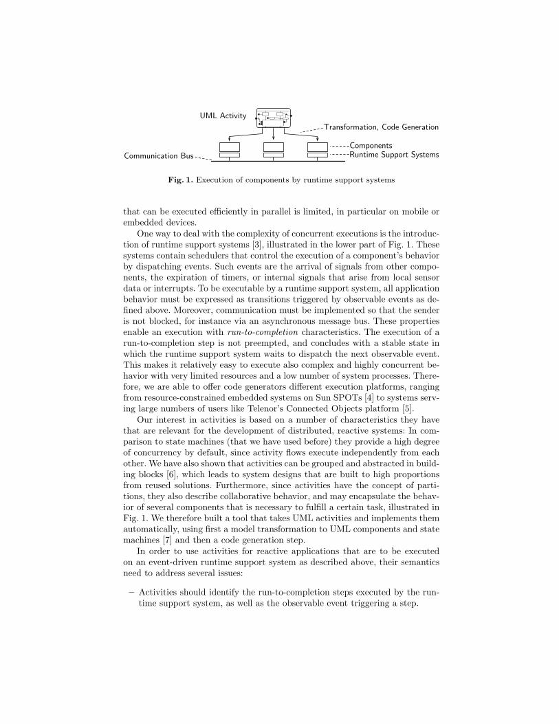
to the activity steps and additional information describing the token settingsbefore resp. after executing the step. Formally, we specify the execution stepof an activity step represented by a subgraph 〈Va, Ea〉 as the quadruple axa =〈Va, Ea, prea, posta〉. prea ∈ tokensA describes the token setting of A before ex-ecuting the activity step, and posta ∈ tokensA denotes the token setting after-wards. For an axa to be valid, it must fulfill the following properties:
– In general, a token is added to accept and queue nodes when their incomingedge is part of an activity step (IX).
– In order to execute, the place representing a trigger must hold a token(AX1). If the trigger place is re-filled within the same step, its token countstays the same (AX3), otherwise it is reduced by one (AX2).
– For join nodes, two rules exist: Rule JX1 models the firing of a join whentokens arrive at its incoming edges. All incoming edges not part of the activ-ity step must already provide a token each. When the join fires, these tokensare deleted, and the step continues with the outgoing edge of the join. RuleJX2 handles the arrival of tokens at a join when it is not yet complete. Asconsequence, it adds these arriving tokens but does not continue.
– Once a final node is part of an activity step, all tokens within the same parti-tion are removed (see rule AFX1 for tokens on edges and AFX2 for tokenson nodes). The latter rule also removes all tokens within queues towards thepartition containing the activity final node. This takes into account that thecomponent implementing the terminated partition is switched off, and anyremaining signals towards it are discarded. The additional precondition
nofinal(n : 2NA, p : PA) , ∀f : f ∈n ∧ partA(f) = p ⇒ kindA(f) 6=afinal
added to rules IX, AX3, JX1 and JX2 ensures that these rules only applyif no activity final node is part of the activity step, to give rules AFX1 andAFX2 priority.
IX
v ∈ Va kindA(v) ∈ {accept, queue}inA(v) ∩ Ea 6= ∅ outA(v) ∩ Ea = ∅ nofinal(Va, part(v))
posta(v) = prea(v) + 1
AX1
v ∈ Va
kindA(v) ∈ {initial, accept, queue}outA(v) ∩ Ea 6= ∅
prea(v) > 0AX2
v ∈ Va
kindA(v) ∈ {initial, accept, queue}outA(v) ∩ Ea 6= ∅ inA(v) ∩ Ea = ∅
posta(v) = prea(v)− 1
AX3
v ∈ Va kindA(v) = accept inA(v) ∩ Ea 6= ∅outA(v) ∩ Ea 6= ∅ nofinal(Va, part(v))
posta(v) = prea(v)
JX1
v ∈ Va kindA(v) = join es = inA(v) ∩ Ea
∀e ∈ inA(v) \ es : prea(e) > 0 nofinal(Va, part(v))
outA(v) ⊆ Ea ∀e ∈ inA(v) \ es : posta(e) = prea(e)− 1
JX2
v ∈ Va kindA(v) = join es = inA(v) ∩ Ea
∃e ∈ inA(v) \ es : prea(e) = 0 nofinal(Va, part(v))
outA(v) ∩ Ea = ∅ ∀e ∈ es : posta(e) = prea(e) + 1
AFX1
e ∈ EA f ∈ Va
kindA(f) = afinal
part(f) = part(targetA(e))
posta(e) = 0AFX2
f ∈Va v∈VA kindA(f) = afinal
part(v) = part(f)
∨ part(v) = 〈 , part(f)〉posta(v) = 0
Fig. 8. Execution rules for activity steps
– All vertices and edges of A not mentioned by one of the rules explicitly donot change their token setting in the execution step axa.
We define the set AXA as the set of execution steps axa each following therules mentioned above. This set contains execution steps that are not reachable.We define the set of reachable execution steps RAXA ⊆ AXA by means of thefollowing two rules:
R1
a ∈ AXA ∀v ∈ VA : kindA(v) = initial⇔ prea(v) = 1∀v ∈ VA : kindA(v) 6= initial⇔ prea(v) = 0 ∀e ∈ EA : prea(e) = 0
a ∈ RAXA
R2
a, b ∈ AXA ∀v ∈ VA : prea(v) = postb(v)∀e ∈ EA : prea(e) = postb(e) b ∈ RAXA
a ∈ RAXA
The rules define recursively that the reachable execution steps a are those con-taining a token setting prea reachable by a finite trace of execution steps from

the initial token setting. The behavior of system SysA is then defined by the statetransition system expressed by the quadruple SysA , 〈VA, EA, initA, RAXA〉.
6 Properties of Activities with Reactive Semantics
In the following, we will discuss the properties of activities with reactive seman-tics. The properties in Sect. 6.2 and 6.3 require additional behavioral invariants,that is, they only hold for a subset of activities. We will assure these by addi-tional rules that have to hold for any a ∈ RAXA. In practice, these rules areverified by model checking, as discussed in [22].
6.1 Event-Driven Execution and Run-to-Completion
As described in the introduction, the events observable by a runtime supportsystem are the expiration of timers, the arrival of internal signals, or the arrivalof signals from other components. On the activity level, these events are modeledby accept event actions and activity flows that cross partition borders via queues.The initial startup of a component is also an event, modeled by initial nodes inactivities. Due to rules T1 and T2, we ensure that each execution step declaresexactly one such trigger, meaning that activity steps started by an observableevent. Furthermore, tokens may be only placed according to two properties:
(i) Tokens may rest on a vertex only if it is of kind initial, accept, or queue.(ii) Tokens may rest on edges if they lead to a join node, but only if the join is
not yet complete, i.e., there is one incoming edge that cannot offer a token.
Property (i) ensures that tokens only wait in places that imply waiting for anobservable event. In initial nodes, this is the start of the system, in queues thearrival of the signal and for accept nodes the expiration of a timer or the arrivalof an internal signal, resp. Property (ii) is more subtle. Tokens may wait onedges preceding join nodes. But since join nodes do not declare any observableevents, tokens may only rest before a join if the join is not yet complete. The joinfires through within the same step once the last missing token arrives. Hence, atoken stored in an incomplete join implies waiting for another observable event.Formally, (i) and (ii) can be expressed as P , E1 ∧ E2 ∧ E3 ∧ E4, with
E1 , ∀v ∈ VA : kind(v) ∈ {initial, accept, queue} ∨ initA(v) = 0
E2 , ∀e ∈ EA : kind(targetA(e)) 6= join ∧ initA(e) = 0∨ ∃f ∈ EA : f ∈ in(targetA(e)) ∧ initA(f) = 0
E3 , ∀v ∈ VA∀a ∈ RAXA : kind(v) ∈ {initial, accept, queue} ∨ posta(v) = 0
E4 , ∀e ∈ EA∀a ∈ RAXA : kind(targetA(e)) 6= join ∧ posta(e) = 0∨ ∃f ∈ EA : f ∈ in(targetA(e)) ∧ posta(f) = 0
E1 and E2 describe that (i) and (ii) hold in the initial state of the system whileE3 and E4 guarantee that all execution steps a∈RAXA preserve them as well.E1 holds due to rules INIT1 and INIT2 and E2 holds due to rule INIT3.

To prove E3, we consider the rules in Fig. 8. The only rule describing thatthe token setting of a vertex v after executing an execution step a can be greaterthan before (i.e., posta(v) > prea(v)) is IX. But according to the second premiseof the rule, the token setting may only be increased for tokens of kind acceptand queue. Thus, if a vertex of a type other than initial, accept or queue has notoken placed on it before the execution of the execution step, it will carry noneafterwards as well. In consequence, it will never carry a token at all.
The proof of E4 is quite similar. The only rule in Fig. 8 modeling an increaseof a token setting on an edge in an execution step is JX2. Yet it does not allowthe placement of new tokens on edges leading to a vertex not being of kind joinas expressed by the third premise. So, the first disjunct of E4 holds and in allsystem states only edges into a join may have tokens at all. Further, the forthpremise of the rule states that there is an edge leading into the join node to whichno token is assigned. As this edge is not an element of the edges receiving newtokens (expressed by set es), it will not carry a token after firing the executionstep. Thus, the second disjunct of E4 holds as well and a join node will alwayshave an incoming edge without a token placed on it.
6.2 Realizability and Distribution
To be executable as one run-to-completion step, an activity step must only havedirect local effects, and only depend on data that is available locally. Rules Qand P1 to P4 split up activity steps at partition borders. Within one activitystep, all nodes except queues are therefore part of the same partition. For flowscrossing partition borders, we take the unavoidable communication delay intoaccount by explicit queue nodes, so that they can be implemented using somecommunication middleware. For some nodes, the general semantics of UML de-scribe also non-local dependencies, that motivate some further constraints:
– As an extension to standard UML, we assume that variables, like activitynodes, are assigned to partitions. Guards and actions are only allowed toaccess variables within their own partition.
– Initial nodes are started simultaneously, but only those within the samepartition. This is already ensured by rule I.
– In standard UML, accept event actions without incoming edge denote thatthey are activated with the surrounding activity. Instead, we require theseactions to have an incoming edge (rule IN3), to model activation explicitly.
– Activity final nodes terminate in standard UML the entire activity. Withthe reactive semantics, they only remove tokens within the same partition(rules AFX1 and AFX2). Since messages towards a terminated partitionare discarded, queues towards a terminated partition are emptied as well.
To comply with the general semantics of activity nodes in which an activity finalnode terminates the behavior in all partitions, the other partitions must not beable to execute any further activity steps. This is ensured by the additionalrules TRM1 and TRM2. The former states that whenever an activity final

TRM1f ∈Va v∈VA kindA(f) = afinal kindA(v) = accept partA(v) 6= partA(f)
prea(v) = posta(v) = 0
TRM2f ∈Va q∈VA kindA(f)=afinal kindA(q) = queue partA(q) 6= 〈 , f 〉
prea(q) = posta(q) = 0
ABv ∈ Va kindA(v) = accept
posta(v) ≤ 1JB
v ∈ Va kindA(v) = join e ∈ inA(v)
posta(e) ≤ 1
QBv ∈ Va kindA(v) = queue
posta(v) ≤ maxqueue
Fig. 9. Additional rules for activities
node is reached, there must not be any token in accept nodes of other partitions.The latter states that all queues not targeting the terminated partition must beempty as well. Since tokens offered to join nodes cannot trigger any behavior ontheir own, they do not have to be removed upon termination.
6.3 Boundedness
Since the number of places needed to describe an activity is limited, the statespace implied by a specification is finite if (and only if) each place only containsa bounded number of tokens, i.e., |tokensA(x) < N |, with N as a finite boundary.Rules IX and JX2 are the only rules increasing token places.
– Accept nodes are either enabled or disabled, represented by one or zerotokens on their corresponding place. We found that adding more than onetoken in an accept node is in most cases unintended and an indicator of adesign flaw. We therefore rule out such behavior by rule AB.
– Places before join nodes can hold many tokens which implies buffering ofdata or control flow. We found that this makes activities harder to under-stand, without adding any expressiveness for reactive systems; we ratherrecommend to use explicit building blocks to describe buffering and rule outbehaviors in which tokens accumulate before joins by rule JB.
– Queues between partitions need to be bounded as well. That means, theymust not exceed a certain value maxqueue ∈ N, expressed by rule QB.
If the boundedness rules hold, the set of reachable execution steps RAXA willbe finite as it is lower or equal to the product of run-to-completion steps timespossible token markings following the boundedness constraints.
7 Concluding Remarks
We described a reactive semantics for UML activities, in which each executionstep is triggered by an observable event. This is motivated by existing mecha-nisms present in runtime support systems for efficient but nevertheless simple

scheduling and execution of highly concurrent behavior. As a consequence of thereactive semantics, the components produced by our model transformation [7]from activities have the same efficiency as if they would have been producedmanually by an experienced designer, i.e., do not contain any overhead for tokencontrol, and it is not visible that they were generated from UML activities.
We have implemented comprehensive tool support with Arctis [22], a set ofEclipse plug-ins. It enables editing, analyzing and automatically implementingactivity-based specifications. The syntactical rules from Fig. 3 are ensured bythe editor, highlighting erroneous parts of the graph. Similarly, the tool canproduce all activity steps implied by a diagram, using the rules from Fig. 5.Rule contradictions that signify illegal diagrams are detected and explained tothe user. Finally, the additional rules for sound behavior in Fig. 9 are verified bymodel checking [22]. Our tool also supports data in activities, which we did nottreat here. Our experience from implementing data shows that their semanticscan be covered by extending the semantics for control flows in a straight-forwardway. Operations with more than one incoming flow, for instance, can be modeledsimilar to join nodes. More advanced nodes can be modeled by dedicated buildingblocks. Concerning the expressiveness of the chosen reactive semantics we pointto numerous case studies (summarized in [6]) that exemplify their application invarious domains. With an abstraction mechanism described in [6] such solutionscan also be encapsulated by dedicated building blocks from which large systemdesigns can be produced in a scalable manner.
References
1. Object Management Group: Unified Modeling Language: Superstructure, version2.2, formal/2009-02-02 (2009)
2. Pnueli, A.: Applications of Temporal Logic to the Specification and Verification ofReactive Systems: A Survey of Current Trends. In: de Bakker, J.W., de Roever,W.P., Rozenberg, G. (eds.) Current Trends in Concurrency. Overviews and Tuto-rials. LNCS, vol. 224, pp. 510–584, Springer (1986)
3. Bræk, R., Haugen, Ø.: Engineering Real Time Systems: An Object-OrientedMethodology Using SDL. Prentice Hall (1993)
4. Kraemer, F.A., Slatten, V., Herrmann, P.: Model-Driven Construction of Embed-ded Applications based on Reusable Building Blocks – An Example. In: Bilgic,A., Gotzhein, R., Reed, R. (eds.) SDL 2009, LNCS, vol. 5719, pp. 1–18, Springer(2009)
5. Herstad, A., Nersveen, E., Samset, H., Storsveen, A., Svaet, S., Husa, K.E.: Con-nected Objects: Building a Service Platform for M2M. In: Beyond the Bit Pipe.Proccedings of the 13th ICIN Conference (2009)
6. Kraemer, F.A., Herrmann, P.: Automated Encapsulation of UML Activities forIncremental Development and Verification. In: Schurr, A., Selic, B. (eds.) ModelDriven Engineering Languages and Systems, 12th International Conference, MOD-ELS 2009, Proceedings. LNCS, vol. 5795, pp. 571–585, Springer (2009)
7. Kraemer, F.A., Herrmann, P.: Transforming Collaborative Service Specificationsinto Efficiently Executable State Machines. In: Ehring, K., Giese, H. (eds.) 6th Int.Workshop on Graph Transformation and Visual Modeling Techniques (GT-VMT),Proceedings. Electronic Communications of the EASST, vol. 7, EASST (2007)

8. Yamaguchi, H., El-Fakih, K., von Bochmann, G., Higashino, T.: Protocol Synthesisand Re-Synthesis with Optimal Allocation of Resources based on Extended PetriNets. In: Distrib. Comput., 16(1) pp. 21–35 (2003).
9. Gunawan, L.A., Herrmann, P., Kraemer, F.A.: Towards the Integration of SecurityAspects into System Development using Collaboration-Oriented Models. In: Secu-rity Technology. International Conference on Security Technology (SecTech 2009),Proceedings. Communications in Computer and Information Science, vol. 58, pp.72–85. Springer (2009)
10. Bock, C.: UML 2 Activity and Action Models, Part 4: Object Nodes. In: Journalof Object Technology, 3(1), pp. 27–41 (2004)
11. Eshuis, R.: Symbolic Model Checking of UML Activity Diagrams. In: ACM Trans-actions on Software Engineering and Methodology, 15(1), pp. 1–38 (2006)
12. Eshuis, R., Wieringa, R.: Comparing Petri Net and Activity Diagram Variants forWorkflow Modelling - A Quest for Reactive Petri Nets. In: Ehrig, H., Reisig, W.,Rozenberg, G., Weber, H. (eds.) Petri Net Technology for Communication-BasedSystems, LNCS, vol. 2472, pp. 321–351. Springer (2003)
13. Storrle, H.: Semantics and Verification of Data Flow in UML 2.0 Activities. In:Electronic Notes in Theoretical Computer Science, vol. 127, pp 35–52 (2005)
14. Storrle, H., Hausmann, J.H.: Towards a Formal Semantics of UML 2.0 Activities.In: Liggesmeyer, P., Pohl, K. Goedicke, M. (eds.) Software Engineering, Fachtagungdes GI-Fachbereichs Softwaretechnik, LNI, vol. 64, pp. 117–128. GI (2005)
15. Barros, J.P., Gomes, L.: Actions as Activities and Activities as Petri Nets. In:Workshop on Critical Systems Development with UML, Proceedings. (2003)
16. Crane, M.L., Dingel, J.: Towards a Formal Account of a Foundational Subset forExecutable UML Models. In: Czarnecki, K., Ober, I., Bruel, J.M., Uhl, A., Vlter,M. (eds.) Model Driven Engineering Languages and Systems, 11th Int. Conference,MoDELS 2008, Proceedings. LNCS, vol. 5301, pp. 675–689. Springer (2008)
17. Crane, M.L., Dingel, J.: Towards a UML Virtual Machine: Implementing an In-terpreter for UML 2 Actions and Activities. In: CASCON ’08: Proceedings of the2008 Conference of the Center for Advanced Studies on Collaborative Research,pp. 96–110, ACM (2008)
18. Engels, G., Soltenborn, C., Wehrheim, H.: Analysis of UML Activities Using Dy-namic Meta Modeling. In: Bonsangue, M.M., Johnsen, E.B. (eds.) FMOODS,LNCS, vol. 4468 pp. 76–90. Springer (2007)
19. Sarstedt, S., Guttmann, W.: An ASM Semantics of Token Flow in UML 2 ActivityDiagrams. In: Virbitskaite, I., Voronkov, A. (eds.) Ershov Memorial Conference,LNCS, vol. 4378, pages 349–362, Springer (2006)
20. Sarstedt, S., Gessenharter, S., Kohlmeyer, J., Raschke, A., Schneiderhan, M.: Ac-tiveChartsIDE: An Integrated Software Development Environment Comprising aComponent for Simulating UML 2 Activity Charts. In: European Simulation andModelling Conference (ESM’05), Proceedings, pp. 66–73 (2005)
21. van der Aalst, W., Hofstede, T.: Workflow Patterns: On the Expressive Power of(Petri-net-based) Workflow Languages. In: Jensen, K. (ed.) Fourth Workshop onthe Practical Use of Coloured Petri Nets and CPN Tools (CPN 2002), Proceedings.DAIMI, vol. 560, pp. 1–20 (2002)
22. Kraemer, F.A., Slatten, V., Herrmann, P.: Tool Support for the Rapid Compo-sition, Analysis and Implementation of Reactive Services. In: Journal of Systemsand Software, 82(12), pp. 2068–2080 (2009)