Embed Size (px)
Citation preview

160 International Journal for Modern Trends in Science and Technology
Reactive Power and AC Voltage Control of LCC HVDC System with Digitally Tunable Controllable Capacitors
O.Gopinath1 | T.Srinivasa Rao2
1,2Department of EEE, , Avanthi Institute of Engineering & Technology, Visakhapatnam ,Andhra Pradesh, India.
To Cite this Article O.Gopinath and T.Srinivasa Rao, “Reactive Power and AC Voltage Control of LCC HVDC System with Digitally Tunable Controllable Capacitors”, International Journal for Modern Trends in Science and Technology, Vol. 03, Issue 06, June 2017, pp. 160-165.
It is well-known that traditional LCC HVDC system is not able to control its reactive power and terminal AC
voltages. This paper investigates the reactive power and AC voltage control at the inverter side of the LCC
HVDC system with controllable capacitors. The system’s ability of operating under negative extinction angle
is utilized to achieve a wide range of reactive power control and, in particular, the ability of exporting reactive
power. The effectiveness of the reactive power/voltage control capability for the proposed system is validated
through simulation results using Real Time Digital Simulator (RTDS). To verify the effectiveness of the reactive
power and voltage control, CCC HVDC and LCC HVDC with SVC are also set up in RTDS. The proposed
concept makes an integration of Fuzzy Logic which assists in accurate control of capacitors and makes the
system efficient by reducing the consumption of Reactive Power. All the results are acquired from the
MATLAB simulations and various graphs are plotted.
KEYWORDS: LCC-HVDC, RTDS, SVC, FUZZY.
Copyright © 2017 International Journal for Modern Trends in Science and Technology
All rights reserved.
I. INTRODUCTION
Most HVDC schemes in commercial operation
today employ line commutated thyristor valve
converters.
Line Commutated Converter
In a line commutated converter, the
commutation is carried out by the ac system
voltage. This brings inherent difficulty in
continuing reliable commutation at very weak ac
system voltages, e.g., during ac system faults. An
ac system is considered to be very weak if the ratio
of [short-circuit power at the point of connection] to
the [rating of the HVDC scheme] is less than 2.
Some HVDC schemes without dc lines operate
successfully with a ratio of less than 1.5. In recent
years converter topologies using series capacitors
in the HVDC converter have also been utilized to
overcome some of these problems. Furthermore,
the increase in reactive power consumption with
the increase of dc power transferred must be taken
into account in the design of the scheme and its
control system. The line commutated converter
based HVDC (LCC HVDC) will continue to be used
for bulk power HVDC transmission over several
hundred MW, because this mature technology
provides efficient, reliable and cost effective power
transmission for many applications.
The reactive power requirement originates from
the firing of thyristors after commutation voltage
becomes positive, which in effect delayed the
current waveforms with respect to the voltage
waveforms [1]. So both rectifier and inverter sides
of the system absorb reactive power. However it
should be noted that to the sending end AC system,
ABSTRACT
International Journal for Modern Trends in Science and Technology
Volume: 03, Issue No: 06, June 2017
ISSN: 2455-3778
http://www.ijmtst.com
161 International Journal for Modern Trends in Science and Technology
O.Gopinath and T.Srinivasa Rao : Reactive Power and AC Voltage Control of LCC HVDC System with Digitally Tunable Controllable Capacitors
the rectifier represents a load and it is natural that
it draws some reactive power from the network just
like other loads. On the other hand, from the point
of view of the receiving end AC system, the inverter
acts as a power producer and as such should take
its share of reactive load.
But the reality is that instead of producing, the
inverter consumes reactive power thus its
consumption level of reactive power should be
minimized. Furthermore, with passive reactive
power compensation at the inverter side, the level
of reactive power being produced tends to decrease
under transient AC voltage drops where reactive
power support is needed most. At the same time,
the minimum extinction angle controller will
advance its firing angle which leads to a higher
reactive power consumption and causes further AC
voltage drops.
These operational characteristics are clearly
unfavorable, and FACTS devices such as
STATCOM and SVC, etc may be needed to mitigate
the problem.
In contrast to what has been described above,
the desired inverter performances are Very low or
zero reactive power consumption level at
steady-state and AC voltage control by inverter
itself especially under large AC disturbances. It
should be pointed out that the reactive power or
voltage controllability at the inverter side should
not be achieved at the expense of reduced active
power transfer level, as the primary role of an
HVDC link is to provide a stable active power
transfer. In this way, the advantage of the inverter
reactive power control can be maximized.
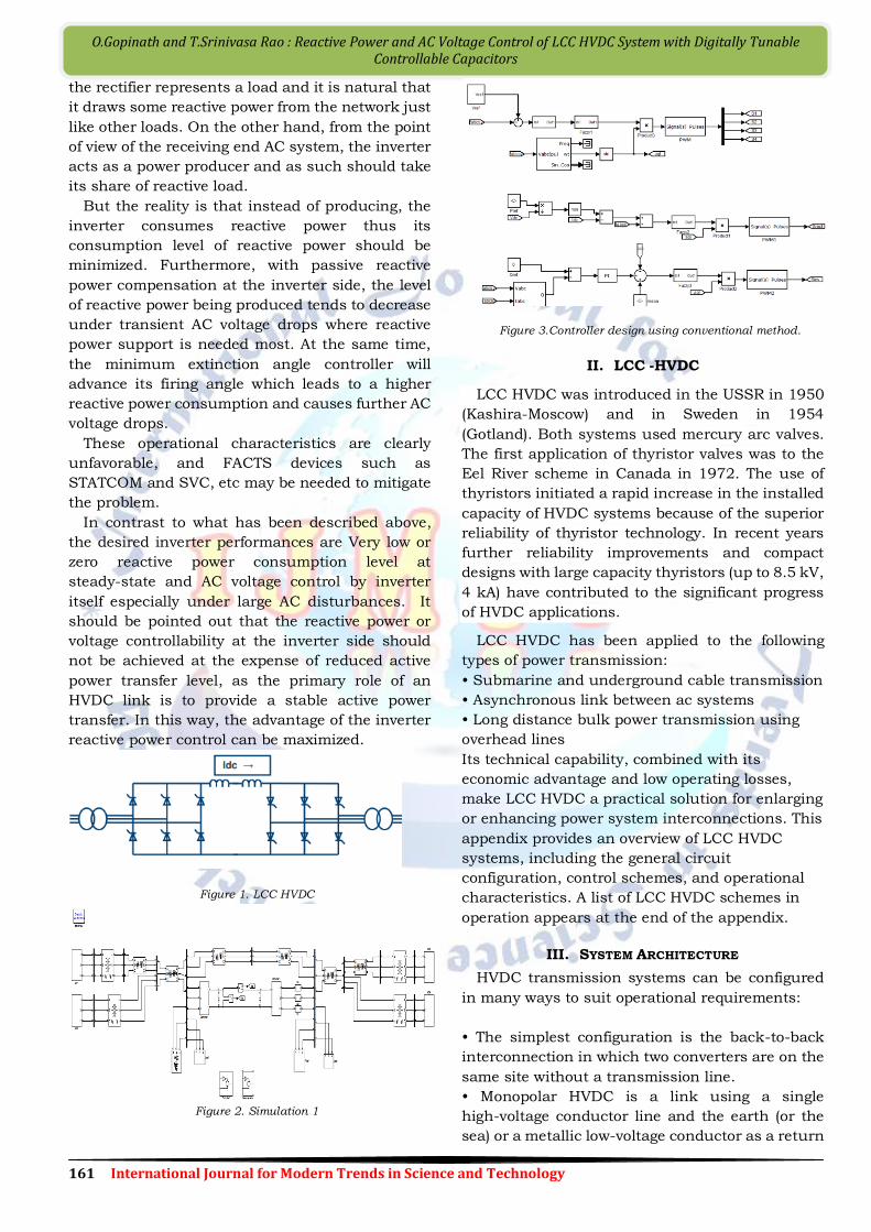
Figure 1. LCC HVDC
Figure 2. Simulation 1
Figure 3.Controller design using conventional method.
II. LCC -HVDC
LCC HVDC was introduced in the USSR in 1950
(Kashira-Moscow) and in Sweden in 1954
(Gotland). Both systems used mercury arc valves.
The first application of thyristor valves was to the
Eel River scheme in Canada in 1972. The use of
thyristors initiated a rapid increase in the installed
capacity of HVDC systems because of the superior
reliability of thyristor technology. In recent years
further reliability improvements and compact
designs with large capacity thyristors (up to 8.5 kV,
4 kA) have contributed to the significant progress
of HVDC applications.
LCC HVDC has been applied to the following
types of power transmission:
• Submarine and underground cable transmission
• Asynchronous link between ac systems
• Long distance bulk power transmission using
overhead lines
Its technical capability, combined with its
economic advantage and low operating losses,
make LCC HVDC a practical solution for enlarging
or enhancing power system interconnections. This
appendix provides an overview of LCC HVDC
systems, including the general circuit
configuration, control schemes, and operational
characteristics. A list of LCC HVDC schemes in
operation appears at the end of the appendix.
III. SYSTEM ARCHITECTURE
HVDC transmission systems can be configured
in many ways to suit operational requirements:
• The simplest configuration is the back-to-back
interconnection in which two converters are on the
same site without a transmission line.
• Monopolar HVDC is a link using a single
high-voltage conductor line and the earth (or the
sea) or a metallic low-voltage conductor as a return

162 International Journal for Modern Trends in Science and Technology
O.Gopinath and T.Srinivasa Rao : Reactive Power and AC Voltage Control of LCC HVDC System with Digitally Tunable Controllable Capacitors
conductor. In recent schemes the use of earth
return is becoming less common because of
environmental opposition.
• The most common configuration is the bipolar
link. Figure 3 illustrates a simplified single-line
diagram of a two-terminal bipolar HVDC
transmission system. With a metallic return, the
earth grounding is made at only one terminal
A few existing schemes have a multi-terminal
configuration in which dc transmission lines
connect three or more terminals at different sites.
Some LCC HVDC schemes have also been provided
with the capability of operating parallel converters
at the ends of a dc transmission line.
Fig 4: One-line diagram of a two-terminal HVDC system
3.1 Converters
The converter performs the energy conversion
between ac and dc. It usually has a 12-pulse
arrangement, in which two 6-pulse bridges are
connected in series on the dc side, as depicted in
Figure 5. The switching of the valves is ordered by
the converter control. The rectifier is the converter
in which power flows from ac to dc, and the inverter
is the converter in which power flows from dc to ac.
The principle of conversion and the waveforms
associated with these conversions are detailed in
references 4 and 5.
Fig 5: Configuration of a 12-pulse bridge
3.2 Converter Transformers
The converter transformers adjust the supplied
ac voltage to the valve bridges to suit the rated dc
voltage. The transformer for a 12-pulse bridge has
a star-star-delta three-winding configuration, or a
combination of transformers in star-star and
star-delta connections.
The converter transformers may be provided as
singlephase or three-phase units. The converter
transformer typically has a leakage reactance of
about 10-18% to limit the current during a
short-circuit fault of the bridge arm.
3.3 Harmonic Filters
Converter operation generates harmonic
currents and voltages on the ac and dc sides,
respectively. On the ac side, a converter with a
pulse number of p generates characteristic
harmonics having the order of np±1 (n=1,2,3,…).
AC filters are installed to absorb those harmonic
components and to reduce voltage distortion below
a required threshold. Tuned filters and high pass
filters are used as ac filters. On the dc side, the
order of harmonics is np. DC filters, along with dc
reactors, reduce the harmonics flowing out into the
dc line. DC filters are not required in cable
transmission or back-to-back schemes.
3.4 Shunt Capacitors
A line commutated converter in steady-state
operation consumes reactive power of about 60% of
the active, or dc, power transferred. The shunt
capacitors installed at the converter ac bus supply
the reactive power required to maintain the
converter ac bus voltage. To achieve satisfactory
power factor for the LCC HVDC converter, the
shunt capacitors are normally subdivided and
switched by circuit breakers as the dc power varies.
Some or all of the shunt capacitors are normally
configured as ac harmonic filters.
3.5 DC Reactors
The dc reactor contributes to the smoothing of
the dc current and provides harmonic voltage
reduction in the dc line. The dc reactor also
contributes to the limitation of the crest current
during a short-circuit fault on the dc line. It should
be noted that the inductance of the converter
transformer also contributes significantly to these
functions.
3.6 DC Connections
Cables or overhead lines are always present on
the pole connections, except in back-to-back
systems. On the electrode connections, many
existing systems use the ground return in normal
operating conditions (monopolar systems) or in
emergency conditions (bipolar systems). However,

163 International Journal for Modern Trends in Science and Technology
O.Gopinath and T.Srinivasa Rao : Reactive Power and AC Voltage Control of LCC HVDC System with Digitally Tunable Controllable Capacitors
because of environmental opposition, the
utilization of ground return is becoming
increasingly problematic and the use of metallic
return (as indicated in Figure 4), although more
expensive, is becoming common, especially for
monopolar systems.
IV. THEORETICAL ANALYSIS OF REACTIVE POWER
CONTROLLABILITY
This section is to examine the reactive power
controllability by capacitor insertion and firing
angle control. The capacitor insertion strategy and
capacitor voltage balancing actions affect the
system from three different aspects. Firstly the
overlap angle is smaller due to additional
commutation voltage from capacitors. Secondly the
average voltage across the 6-pulse bridge is
increased due to the difference of capacitor voltage
change during commutation.
Thirdly the pre-insertion of capacitors for
charging purpose also increases the average bridge
voltage. In the following, analytical derivations will
be presented for all three aspects and then
variation of power factor (interchangeably variation
of reactive power) as a function of firing angle and
extinction angle will be shown. In addition,
selection of capacitor voltage level for the desired
operating range is also presented.
V. FUZZY LOGIC CONTROLLER
In HVDC Light transmission systems, active and
reactive power is controlled by using different types
of controllers. In general, conventional PI
controllers are used for this application.
The gain values used in conventional PI controlled
system are:
KP = 3; KI = 20 (For P and Q control modes at
station 1)
KP = 2; KI = 40 (For DC voltage control mode at
station 2)
KP = 3; KI = 25 (For Q control mode at station 2)
But, these controllers are designed to work at a
particular operating point; any disturbance may
cause deterioration of the controller performance.
To avoid such a situation, fuzzy PI controllers are
introduced to control above parameters in the
HVDC Light transmission systems. It shows the
overall structure of the proposed controller. In this
research work, four PI controllers are used to get
faster response and smaller overshoot. Inner
structure of the fuzzy PI controller. The basic fuzzy
logic controller is composed of four function blocks.
Fig6: Controller design using proposed method
These are fuzzifier block, knowledge base,
inference engine and defuzzifier block. There are
two inputs for each of the fuzzy logic controller,
namely, error (e), change of error (de) and the
output known as gain(Kp and Ki) [12]. Here, the
data of two inputs i.e. error and change of error are
transformed into linguistic variables by fuzzifier.
Then, the linguistic variables are processed by the
fuzzy rules in the rule base in the form of “If – Then”
through fuzzy implication.
To fuzzify both input data and output, triangular
membership function set is used in this paper with
five linguistic variables viz, Negative large (NL),
Negative small(NS), zero (Z), positive small (PS) and
positive large (PL). The membership functions used
for the input and output variables in the fuzzy logic
tool box are shown in Fig.6. The knowledge base
unit has two components, the data base and the
rule base.
VI. EXPERIMENTAL RESULTS
This section presents the simulation results of
reactive power control and inverter AC voltage
control of the LCC HVDC system with controllable
capacitors. The nominal operating point for both
cases is designed so that the inverter side is
absorbing zero reactive power and sending rated
active power at rated DC and AC voltages. The
capacitor banks are removed and transformer
turns ratio is modified to meet the rated working
condition. The values of capacitors are 585uf and
its voltage level is chosen to be 110 kV. The rectifier
side is controlling the active power transfer by
controlling the DC current. The AC systems at both
sides are kept the same as the CIGRE HVDC
benchmark model. The whole system is modelled in
RTDS with a small simulation time-step of3.6us .
A. Reactive Power Control
Fig. 7 shows the system responses following
changes of reactive power reference. In this

164 International Journal for Modern Trends in Science and Technology
O.Gopinath and T.Srinivasa Rao : Reactive Power and AC Voltage Control of LCC HVDC System with Digitally Tunable Controllable Capacitors
simulation, the reactive power reference is initially
set to zero and changes to -150 MVar at 3.1s, then
increases to 150 MVar at 4.6s and finally changes
back to zero at 6.1s. Negative reactive power
indicates that the inverter is exporting reactive
power to the AC system.
(a), (b)
(c), (d), (d)
Fig. 7. System responses with reactive power reference
step changes. (a) Reactive power consumption at inverter;
(b) Active power transfer; (c) DC voltage; (d) DC current; (e)
Inverter firing angle.
Simulation response.
(a)
(b)
(c)
(d)
(e)
(f)
165 International Journal for Modern Trends in Science and Technology
O.Gopinath and T.Srinivasa Rao : Reactive Power and AC Voltage Control of LCC HVDC System with Digitally Tunable Controllable Capacitors
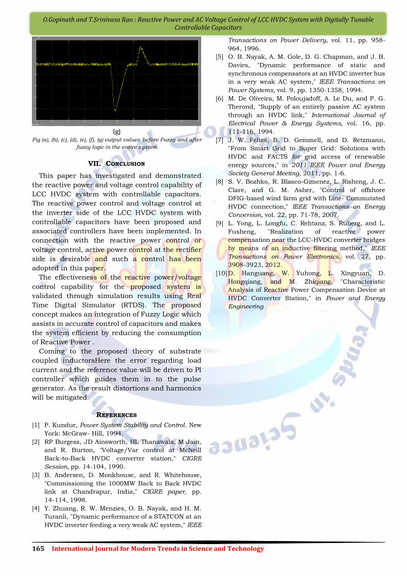
(g)
Fig (a), (b), (c), (d), (e), (f), (g) output values before Fuzzy and after
fuzzy logic in the entire system
VII. CONCLUSION
This paper has investigated and demonstrated
the reactive power and voltage control capability of
LCC HVDC system with controllable capacitors.
The reactive power control and voltage control at
the inverter side of the LCC HVDC system with
controllable capacitors have been proposed and
associated controllers have been implemented. In
connection with the reactive power control or
voltage control, active power control at the rectifier
side is desirable and such a control has been
adopted in this paper.
The effectiveness of the reactive power/voltage
control capability for the proposed system is
validated through simulation results using Real
Time Digital Simulator (RTDS). The proposed
concept makes an integration of Fuzzy Logic which
assists in accurate control of capacitors and makes
the system efficient by reducing the consumption
of Reactive Power .
Coming to the proposed theory of substrate
coupled inductorsHere the error regarding load
current and the reference value will be driven to PI
controller which guides them in to the pulse
generator. As the result distortions and harmonics
will be mitigated
REFERENCES
[1] P. Kundur, Power System Stability and Control. New
York: McGraw- Hill, 1994.
[2] RP Burgess, JD Ainsworth, HL Thanawala, M Jain,
and R. Burton, "Voltage/Var control at McNeill
Back-to-Back HVDC converter station," CIGRE
Session, pp. 14-104, 1990.
[3] B. Andersen, D. Monkhouse, and R. Whitehouse,
"Commissioning the 1000MW Back to Back HVDC
link at Chandrapur, India," CIGRE paper, pp.
14-114, 1998.
[4] Y. Zhuang, R. W. Menzies, O. B. Nayak, and H. M.
Turanli, "Dynamic performance of a STATCON at an
HVDC inverter feeding a very weak AC system," IEEE
Transactions on Power Delivery, vol. 11, pp. 958-
964, 1996.
[5] O. B. Nayak, A. M. Gole, D. G. Chapman, and J. B.
Davies, "Dynamic performance of static and
synchronous compensators at an HVDC inverter bus
in a very weak AC system," IEEE Transactions on
Power Systems, vol. 9, pp. 1350-1358, 1994.
[6] M. De Oliveira, M. Poloujadoff, A. Le Du, and P. G.
Therond, "Supply of an entirely passive AC system
through an HVDC link," International Journal of
Electrical Power & Energy Systems, vol. 16, pp.
111-116, 1994.
[7] J. W. Feltes, B. D. Gemmell, and D. Retzmann,
"From Smart Grid to Super Grid: Solutions with
HVDC and FACTS for grid access of renewable
energy sources," in 2011 IEEE Power and Energy
Society General Meeting, 2011, pp. 1-6.
[8] S. V. Bozhko, R. Blasco-Gimenez, L. Risheng, J. C.
Clare, and G. M. Asher, "Control of offshore
DFIG-based wind farm grid with Line- Commutated
HVDC connection," IEEE Transactions on Energy
Conversion, vol. 22, pp. 71-78, 2007.
[9] L. Yong, L. Longfu, C. Rehtanz, S. Ruberg, and L.
Fusheng, "Realization of reactive power
compensation near the LCC-HVDC converter bridges
by means of an inductive filtering method," IEEE
Transactions on Power Electronics, vol. 27, pp.
3908-3923, 2012.
[10] D. Hanguang, W. Yuhong, L. Xingyuan, D.
Hongqiang, and M. Zhiqiang, "Characteristic
Analysis of Reactive Power Compensation Device at
HVDC Converter Station," in Power and Energy
Engineering


![ICREPQ17 - Present and future multiterminal HVDC systems ... · technologies, it can be seen that future HVDC grids are going to be based on this technology [3]. 3. LCC-MTDC systems](https://img.dokumen.tips/doc/110x75/5acf70b47f8b9a71028ca2fe/icrepq17-present-and-future-multiterminal-hvdc-systems-it-can-be-seen-that.jpg)


![Studies of commutation failures in hybrid LCC/MMC HVDC systems · The length of its transmission line is 3293 km [5]. However, the LCC-HVDC technology still has a few inherent shortcomings](https://img.dokumen.tips/doc/110x75/5f3961d78fc98b62ce527484/studies-of-commutation-failures-in-hybrid-lccmmc-hvdc-systems-the-length-of-its.jpg)