Embed Size (px)
Citation preview
Reactive direction control for a mobile robot: A locust-like control of escape direction emerges when a bilateral pair of model locust visual neurons are integrated Shigang Yue1,4↓ Roger D. Santer2, Yoshifumi Yamawaki3 and F. Claire Rind4 1Brain Mapping Unit, Sir William Hardy Building, Downing Site, University of Cambridge, CB2 3EB UK 2School of Biological Sciences, University of Nebraska – Lincoln, Lincoln, NE 68588, USA 3Department of Biology, Faculty of Science, Kyushu University, Fukuoka 812-8581, JAPAN 4Ridley Building, School of Biology and Psychology, University of Newcastle upon Tyne, NE1 7RU UK Abstract Locusts possess a bilateral pair of uniquely identifiable visual neurons that respond vigorously to the image of an approaching object. These neurons are called the lobula giant movement detectors (LGMDs). The locust LGMDs have been extensively studied and this has lead to the development of an LGMD model for use as an artificial collision detector in robotic applications. To date, robots have been equipped with only a single, central artificial LGMD sensor, and this triggers a non-directional stop or rotation when a potentially colliding object is detected. Clearly, for a robot to behave autonomously, it must react differently to stimuli approaching from different directions. In this study, we implement a bilateral pair of LGMD models in Khepera robots equipped with normal and panoramic cameras. We integrate the responses of these LGMD models using methodologies inspired by research on escape direction control in cockroaches. Using ‘randomised winner-take-all’ or ‘steering wheel’ algorithms for LGMD model integration, the khepera robots could escape an approaching threat in real time and with a similar distribution of escape directions as real locusts. We also found that by optimising these algorithms, we could use them to integrate the left and right DCMD responses of real jumping locusts offline and reproduce the actual escape directions that the locusts took in a particular trial. Our results significantly advance the development of an artificial collision detection and evasion system based on the locust LGMD by allowing it reactive control over robot behaviour. The success of this approach may also indicate some important areas to be pursued in future biological research. Keywords robots, escape, emergent properties, behaviour, visual neural network, LGMD, DCMD, locusts, jumping, agents, hybrid, cybernetics
↓ Corresponding author, current address: School of Computer Science, University of Lincoln Brayford Pool, Lincoln, LN6 7TS United Kingdom Tel: (0044) 01522 837397 Fax: (0044) 01522 886974 Email: [email protected] or [email protected]
2009 to Autonomous Robots (revised)

Page 2 of 28
1. Introduction Animals often possess incredible sensory systems that allow them to detect the details of their environment. These systems enable animals to react quickly and appropriately to any changes in the environment that their sensory systems detect. Some of the most important environmental stimuli are attacking predators and in many animal species sensory and motor systems have evolved to help them detect and evade these kinds of approaching threats (for example, Wine and Krasne 1972, Camhi et. al. 1978, Robert et. al. 1981, and Gnatzy 1996). The same is not true of the artificial sensors used in robotic control. For autonomous mobile robots, the ability to avoid collision and interact with the dynamic environment is an important one and, often, several kinds of sensors - including visual, ultrasound, infra-red, laser, and mini-radar (for examples see Everett 1995, Adams 1998, Manduchi et. al. 2005) – are used to mediate these interactions. Of these, vision is best able to provide a broad array of environmental information simultaneously in real time, but unfortunately, traditional segmentation and registration based computer vision methodologies cannot cope with the degree of complexity in the visual world for real time collision detection applications (Yue and Rind, 2006a). It is still very difficult for a robot to run autonomously without collision in complex, outdoor environments without human intervention (Indiveri and Douglas 2000, DeSouza and Kak 2002) partially because the robot can’t make a fast, reactive decision on how to behave when faced with a particular threat A potential solution to these shortcomings is to mimic the behaviour of animals which have relatively simple collision avoidance behaviours, but make rapid decisions on how to direct them when needed. Locusts have a finely evolved predator-evasion system, as anyone who has tried to capture one will testify. One of the reasons that locusts are so difficult to catch is that their visual system contains two bilateral pairs of identified neurons that respond to the image of an approaching object. These are the lobula giant movement detectors (LGMDs), and their postsynaptic partners, the descending contralateral movement detectors (DCMDs) (Schlotterer 1977, Rind and Simmons 1992, Simmons and Rind 1992, Gabbiani et.al. 2004, 2006). Because a DCMD reproduces spikes (action potentials) from an LGMD on a 1:1 basis, their responses are the same. As an object approaches, these cells produce a train of spikes that increases in frequency (Rind and Simmons, 1992). These spikes excite motor and interneurons postsynaptic to the DCMD that, in flight, can cause the locust to produce a pause in flight that is interpreted as an emergency escape dive (Simmons, 1980, Santer et. al., 2006). The input circuitry of the LGMD neuron has been used as inspiration for an artificial visual system that mediates collision avoidance in robots and, more recently, in cars (Blanchard et. al 1999, 2000, Rind and Bramwell 1996, Rind and Simmons 1999, Rind 2002, 2005, Rind et. al. 2003, 2004, Santer et. al. 2004, Yue and Rind 2005, Yue et. al. 2006a, Yue and Rind 2006a~b, 2007, 2008a~b). This LGMD-based neural network, as adapted for use in a VLSI circuit for use in cars, can provide a robotic vision solution in

Page 3 of 28
complex environments and under extreme illumination conditions (Stafford et. al. 2007, Yue et. al. 2006a). However, thus far it has been used only to trigger stereotyped motor responses in a mobile robot – anti-clockwise turns or stops for example – without any directional control relative to the direction from which a threat develops. This is a useful and important ability in an escape system or a collision avoidance system, especially in a robot that is intended to run autonomously. When on the ground, real locusts escape from approaching threats by jumping. Rather than precisely directing these jumps, locusts have a rather coarse control over their jump direction meaning that they always jump away from an approaching object, but their exact trajectories are highly variable (Santer et al., 2005b). In theory, this simple escape strategy could be useful for a mobile robot to reactively avoid collision without taking a long time to make a decision on a precise escape trajectory. In real locusts there have been no studies of the possible role for the LGMDs or DCMDs in jump direction control and, although there have been several on jump triggering, none has established the exact role of the DCMD (Hatsopoulos et. al., 1995, Stafford and Rind 2007, Fotowat and Gabbiani 2007, Santer et al 2008). However, in the escape responses of cockroaches to wind puffs, the responses of six directionally-selective wind-sensitive giant interneurons are integrated to give a precise control of escape direction (Levi and Camhi 2000a, 2000b, Ezrachi et. al. 1999, Ezrachi 2003). Because locusts have a bilateral pair of LGMDs (one responding to objects looming towards the left compound eye, the other to objects looming towards the right compound eye, and therefore providing a coarse indication of the direction from which an object is approaching), we wondered whether integrating the responses of these two neurons in a similar way could result in a simple, reactive, locust-like left-right control of escape direction.
To test the effectiveness of this method of reactive direction control, we equipped Khepera robots with a bilateral pair of model LGMD neurons and integrated their responses using the algorithms investigated for cockroaches. We then repeated the investigation of locust escape direction of Santer et al (2005b) using our LGMD-equipped robots instead of real locusts. We found that, in our robots, a locust-like control of escape direction was an emergent property of the integration of the left and right LGMD model responses. We also recorded the left and right DCMD responses of a locust performing real escape jumps and integrated these spike trains offline using the same algorithms as in our robotic experiments (optimised for this task using a GA). Through this method, we could use our algorithms to generate the jump direction that a locust took in a particular trial based on its computationally-integrated DCMD responses alone. These results significantly advance the usefulness of the LGMD model for autonomous robot control in the real world, and indicate how simple integration algorithms can reproduce behavioural responses. 2. Methods In this section, we describe the construction of a locust-inspired visual collision detection system with reactive escape direction control, robotic experiments, and agent experiments based on spike trains recorded from the DCMDs of real locusts during escape responses.

Page 4 of 28
The reactive escape system, including the pair of LGMD models and the fusion network that integrated their responses, together with the implementation of the system in mobile robots, and the robotic experiments, are described in subsection 2.1; a further test of the fusion network using DCMD activity recorded from real locusts is reported in subsection 2.2. 2.1 The reactive escape system The reactive escape system in this study includes a collision detection system and a coarse direction control system. The collision detection system detects imminent collision and triggers the a reactive escape response. The coarse direction control system controls the escape direction by integrating the outputs of the collision detection system. Once integrated to a mobile robot, the affiliate hardware became part of the system as a whole, as shown in Figure 1 (a). The CCD camera of the robot captures images in real time; the images are split into two halves and fed to the left and right LGMD model (Figure 1 (b)); the LGMD model spikes are used to trigger escape; the outputs of LGMD model are also processed by a fusion network which integrates their responses and controls the robot’s escape direction. 2.1.1 The LGMD model The LGMD model (Figure 1 (b)) used in this study is based on the neural network described in Rind and Bramwell (1996), Blanchard et. al. (2000), Stafford et. al. (2004), and Yue and Rind (2005, 2006a). The left and right LGMD share the same spatiotemporal structure. A brief description of one of the LGMDs used in this study is given below, but the precise details of this model’s performance in real world collision detection applications can be found in the above references. The LGMD model responds to movement in depth or ‘looming’. The network is composed of four layers of cells - photoreceptor (P), excitatory (E), inhibitory (I) and summing (S), and two single cells - feed-forward inhibition (FFI) and LGMD. In the first layer of the neural network are the photoreceptor (P) cells which are arranged in a matrix. The luminance Lf of each pixel in the input image at frame f is captured by each photoreceptor cell. The change in luminance Pf between frames of the image sequence is then calculated and forms the output of this layer. The output of a cell in this layer is defined by the equation:
),(),(),( 1 yxLyxLyxP fff −−= (1) where Pf(x,y) is the change in luminance corresponding to pixel (x,y) at frame f; x and y are the pixel coordinates, Lf and Lf-1 are the luminance, subscript f denotes the current frame and f-1 denotes the previous frame. The outputs of the P cells form the inputs to two separate cell types in the next layer. One type is the excitatory (E) cells, through which excitation is passed directly to the

Page 5 of 28
retinotopically arranged counterpart of the cell in the third layer, the S layer. The second cell type are the lateral inhibition (I) cells, which pass inhibition, after a 1 image frame delay, to the cells in retinotopically neighbouring positions to their own in the S layer. The strength of inhibition delivered to a cell in this layer is given by:
)0,(),,(),(),( 1 =≠++= −−= −=∑ ∑ iifjijiwjyixPyxI If
n
ni
n
njf
(2)
where If(x,y) is the inhibition corresponding to pixel (x,y) at the current frame f, wI(i, j) are the local inhibition weights, and n defines the size of the inhibited area. In our experiments, the local inhibition weights are set to 25% for the inhibition from the four directly neighbouring cells and 12.5% for the inhibition from the diagonally neighbouring cells; and n was set to 1. Excitation from the E cells and inhibition from the I cells are summed by the S cells in layer 3 of the network using the following equation:
Ifff WyxIyxPyxS ),(),(),( −= (3) where WI is the global inhibition weight and is set to 0.3 in our experiments. Excitation that exceeds a threshold value is passed to the LGMD cell:
<≥
=rf
rfff TyxSif
TyxSifyxSyxS
),(0),(),(
),(~ (4)
where Tr is the threshold and is set to 15 in these experiments. The membrane potential of the LGMD cell Uf, is the summation of all the excitation in the S cells as described by the following equation,
∑∑= =
=k
x
l
yff yxSU
1 1
),(~( (5)
The membrane potential Uf is then transformed to a spiking output using a sigmoid transformation,
1)1(1
−− −
+= cellf nUf eu (6)
where ncell is the total number of cells in the S layer. Since Uf is greater than, or equal to zero, the sigmoid membrane potential uf varies from 0.5 to 1. A collision alarm is caused by spiking in the LGMD cell. If the membrane potential uf exceeds the threshold Ts, a spike is produced. A certain number of successive spikes, denoted by SLGMD, will trigger the collision alarm. In the experiments, ncell is 8,000 and Ts is 0.75. In the absence of feed forward inhibition (FFI), the network may produce spikes and a false collision signal when challenged by a sudden whole-field change in the visual scene,

Page 6 of 28
for example during a rapid turn (Santer et.al. 2004). The feed forward inhibition cell negates such responses when a large number of photoreceptors are simultaneously excited (Rind and Bramwell 1996). The FFI at a given frame is taken from the summed output of the photoreceptor cells with one frame delay,
1
1 11 )),(( −
= =−∑∑= cell
k
x
l
yff nyxPF (7)
Once Ff exceeds its threshold spikes in the LGMD are inhibited immediately. The threshold of the FFI cell is set to 20. In locusts, the LGMD’s postsynaptic partner, the DCMD, spikes with a 1:1 relationship with the LGMD and so does a pair of DCMDs in the model. The spikes of the pair of DCMDs are used to initiate emergent escape behaviour and are fed to a fusion network which integrates their responses and translates them into a motor command to control the direction of escape that the robot takes. In the next subsection we describe these fusion networks. 2.1.2 Coarse direction control system In the escape behaviour of cockroaches to wind puffs, the responses of six directionally-selective wind-sensitive giant interneurons are thought to be integrated to give a precise control of escape direction (Levi and Camhi 2000a, 2000b, Ezrachi et.al. 1999, Ezrachi 2003). Here we use similar mechanisms of integration on the left and right model LGMD responses to mimic the locust’s left-right control of escape direction. In this study we implement two types of fusion networks to integrate the outputs from the two model DCMDs. One fusion network is a winner-take-all network (Roberts, 1968, Krasne and Lee, 1988, Eaton et. al. 1991, Salzman and Newsome, 1994, Levi and Camhi 2000a), with which the DCMD controlling a given direction of escape behaviour suppresses the other DCMD specifying the alternative direction (Figure 1 (c)). As shown in Figure 1 (c), the spikes from the two DCMDs are first compared at cell a. The DCMD with more spikes is the winner and the robot/agent is prepared to turn in that direction. The emergent escape behaviour is triggered by several (Nsp) successive spikes from either left or right DCMDs. If the number of spikes from the left DCMD is SDl and from the right DCMD is SDr, the escape direction can be formulated as:
spDrn
ni
DrDl
spDln
ni
DrDl
Dr
Dl
dir
NSSSif
NSSSif
SS
D>=<
>=>
=∑
∑
−=
−=
4
4
&
& (8)
where n is an integer representing a spike at a time step, Nsp is an integer number, often set to 4 or 5 empirically, depending on factors such as image frame rate per second,

Page 7 of 28
robotic control system, computing power etc. Note that in the above equation, the ‘loser’ contributes nothing to Ddir. Occasionally, the left and right DCMD produced the same number of spikes. This would be rare for a locust since its DCMD spikes at very high frequency, much higher than its modelled counterpart. The DCMD model works at 25Hz or lower, so its left and right DCMD may sometimes produce the same number of spikes at the time of escape. It is also obvious that a mobile robot can only move on a two dimensional surface. To initiate a successful escape in this case, a randomised direction is more practical,
)(&,)1(44
0101spDr
n
ni
spDln
ni
DrDlDrDldir NSorNSSSifSRSRD >=>==−+= ∑∑
−=−=
(9)
where R01 is randomly generated binary number either 1 or 0. A transformation needs to be done to turn spike number to robotic turn time period using the following equation,
dirdir DT 1λ= (10) the unit of time Tdir is seconds, λ1 is a coefficient obtained experimentally. Given the turning speed of a robot, the longer the Tdir, the bigger the escape angle Θ. According to equation (8)-(10), if the left DCMD generates Nsp successive spikes earlier than the right side LGMD, the robot will turn to the right side before escape because the left DCMD is the winner. The turning angle will be decided by the time value calculated using the above equations. This is supported by biological experiments in which locusts begin to steer their jump with their forelegs prior to lifting off with their hindlegs (Santer et al, 2005). In the experiments, λ1 is set to 0.1 for normal vision and 0.05 for panoramic vision, Nsp is set to 5 for normal vision and 4 spikes for the panoramic vision because of the lower frame rate resulting from panoramic image transformation. The second implemented fusion network is a collaborative, or steering-wheel (Levi and Camhi 2000b) network; this mechanism allows the two DCMD outputs to reach both circuits controlling different escape directions but in an additive way, as shown in Figure 1 (d). In this case, the final turning angle before escape is the cummulative effects of the two DCMD outputs in turn, that is to say, the turning angle is decided by:
)(2DlDr
dir SST −= λ (11) where λ2 is also a coefficient and is set to 0.1 empirically. The same measure, i.e. randomised escape direction as defined in equation (9), has been taken when the two DCMDs send out the same number of spikes at the time escape behaviours starts. In some experiments we were interested to see whether additional random factors, representing the involvement of other neurons in triggering the escape behaviour or motor errors, were needed to generate variability in escape trajectory. To implement an

Page 8 of 28
additional random factor into the robotic direction control system, the Tdir has to be modified as,
rdirdirR RTT 3λ+= (12) where λ3 chosen between 0-0.5 and Rr is a random real number between 0 and 1. Note that if λ3 is not zero, then Tdir has to be modified to maintain an equivalent length of turning time. For example, when λ3 is 0.3, then λ1 is reset to 0.04 to keep the total maximum turning time 0.5s; if λ3 is 0.5, then λ1 is reset to 0 to keep the total maximum turning time 0.5s. For the robot with panoramic vision, λ3 is 0.025, then λ1 is reset to 0.10 to keep the total maximum turning time 0.25s. When the random factor is implemented, we refer to the two fusion networks as ‘randomised winner-take-all’ or ‘randomised steering wheel’ mechanisms. 2.1.3 Implementation Model LGMD and fusion networks were written in Matlab® (the MathWorks, USA) and run on a PC. Input to the paired LGMD models was from the CCD camera of a Khepera mobile robot (K-team, Lausanne, Switzerland) (Figure 2 a, c). We used either a normal grey scale CCD camera (field of view approx. 60 degrees, Figure 2 b) or a panoramic vision camera (field of view is 360 degrees, Figure 2d). Communication between the PC and the robot was via a serial port through an RS232 cable. Images captured by the robot’s CCD camera were fed to the model LGMDs and processed in real time. For the robot with normal vision, the size of the whole image fed to LGMDs was 100 pixels horizontally and 80 pixels vertically. When the panoramic vision camera was used (Figure 2 c), images were transformed from panoramic images (Figure 2 d) into normal images (Figure 2 e) using programmes written in Matlab and then fed to the LGMD/DCMD model for processing. The transformation involved rearranging pixels to a different coordinate system, i.e., from a Polar to a Cartesian coordinate system; the grey scale at each pixel remains unchanged (Figure 2 d). For the robot with panoramic vision, the size of the whole image fed to the LGMDs was 360 pixels horizontally by 42 vertically. The LGMD spiking threshold was set to 0.6 when panoramic vision was used. For both camera types, the image (either directly from the camera or transformed from a panoramic image) was divided into two bilateral halves with a 10 degree overlap in the central region, mimicking the fields of view of insect compound eyes (Horridge 1978; Stern and Gewecke 1993). These were each used as input to one of the LGMD models making a left right bilateral pair as in the real locust. Examples of the outputs from the LGMD models challenged by a rolling cylinder from two different angles are shown in Figure 3. The robot had panoramic vision in the examples. Note that in a real world experiment (Figure 3 a), the left and right LGMD generated different numbers of spikes though the cylinder rolled towards the CCD directly from behind. 2.1.4 Robotic experiments

Page 9 of 28
Using robotic experiments, we wanted to determine whether a coarse, locust-like control of escape direction could be mimicked by the integration of left-right LGMD model responses and whether this could serve as a useful collision avoidance system for a robot running autonomously. We used a series of robotic experiments to address this. A Khepera II robot with normal vision and a Khepera II robot with 360 degree vision were used in these experiments. We tested the two algorithms described above (winner-take-all and steering wheel) for integrating its right and left model LGMD responses which have been recently investigated for the cockroach escape system (Levi and Camhi 2000a, 2000b, Ezrachi et.al. 1999, Ezrachi 2003). Initially we used the same rolling ball stimulus that was used to trigger directed escape jumps in locusts by Santer et al (2005b). The ball was rolled at different angles (varying at 5 degrees increments) toward the normal camera of a Khepera robot. Using its paired model LGMDs and subsequent method of integration, the robot was expected to detect the collision, turn to a direction, move along that direction for 3 seconds and stop. The directions were then measured according to the final position of the robot to the fixed start position. For each angle, 5 trials were conducted. The robots’ escape behaviours were triggered by several successive LGMD model spikes, as mentioned in the above section, e.g. 5 successive spikes for the robot with normal vision and 4 successive spikes for the robot with panoramic vision. An infrared sensor was also used to trigger the robot’s escape behaviour for one of the experiments, in order to investigate the possible effects of direction control by the LGMD/DCMDs and escape triggering by another mechanism. In this situation, the rolling ball hit a long curved strip of white paper at the end of its approach (about 10cm long and 3cm wide folded to 1.5cm wide cut from 8g A4 paper). This paper blocked one front infrared sensor of the robot and was knocked away by the rolling ball, allowing the infrared sensor to detect the ball’s approach. The infrared sensor worked at approximately 50 Hz. Escape angles were largely determined by the robot’s turning speed and turning time affected by some other minor random factors, such as internal system errors of the robot and mechanical characteristics of the test bed. The turning speed of the robot was determined by the speeds of its wheels. For the robot with normal vision, the left wheel was set to 3.2cm/s and the right -3.2cm/s to allow the robot to turn around the centre point between the two wheels. The turning time was set to 0.3s experimentally to ensure the maximum turning angle was around 45 degrees. The robotic agent system can process 25 images per second in the experiments. For the robot with 360 degrees vision, a wider range of ball approaching angles was used in a larger series of experiments. The turning speed of the robot was set in the same way as before but at 6.4cm/s. The turning time was set to 0.2s experimentally to ensure the maximum turning angle is around 45 degrees. The robotic agent with panoramic vision can process approximately 11 images per second. 2.2 Computational integration of real DCMD spike trains
Page 10 of 28
We also wanted to know whether the above fusion mechanisms can integrate real recorded left and right DCMD spikes of a real escaping locust and reproduce its actual escape direction. The interpretation of the real animal’s visual neuron spikes into a motion control signal is also an important step towards a visual neuron controlled hybrid robotic system. In the robotic system, the maximum LGMD model spiking rate is 25 Hz for normal vision and 11 Hz for panoramic vision. The escape behaviour of a robot is triggered by several successive spikes. In a real locust, the maximum DCMD spiking rate is much higher, for example, the peak firing rate can be >400 Hz. It is therefore biologically plausible for the computational models to look at excitation resulting from the left and right DCMDs spikes rather than counting the spikes themselves. We use agents to represent the systems which read spike trains and output escape directions. For example, a winner-take-all agent uses the winner-take-all algorithm to integrate the spike trains from left and right DCMDs to generate escape directions. Similarly, a steering wheel agent uses the steering wheel algorithm. 2.2.1 DCMD spike train recording In locusts, the LGMD’s postsynaptic partner, the DCMD, spikes with a 1:1 relationship with the LGMD and so by recording it, we can ascertain the locust LGMD response (Rind, 1984). Spike trains from a real locust’s left and right DCMD neurons were recorded as the animal performed escape jumps in response to a rolling ball stimulus as used in Santer et al (2005b). Recordings were made using a pair of hook electrodes that were implanted as in Santer et al (2005a). These recordings were amplified and captured to disc using a CED micro1401 and Spike2 v 5 for Windows (Cambridge Electronic Design). In total, we made thirteen successful recordings in which left and right DCMD activity was clear during the performance of an escape jump. In each case, the ball stimulus approached from a different direction and we high-speed filmed the jump of the locust (using a Redlake, Motionscope PCI high speed camera) and recorded DCMD spikes simultaneously (Figure 8a). The locust’s escape directions were extracted manually (Figure 8b) from the recorded video clips. 2.2.2 Integration of real DCMD spike trains for escaping agents We wanted to see if a similar integration strategy to the one we employed with bilateral paired model LGMDs could integrate the DCMD responses of real locusts to reproduce locust escape directions. In these experiments we created computational ‘agents’ that integrated the left and right DCMD responses recorded from a freely jumping locust to determine a direction of escape. These agents read the recorded left and right DCMD responses as the outputs of their left and right DCMDs. They then outputted escape trajectories by using (1) the winner-take-all model and (2) the steering wheel model as detailed in the above section. We found that both winner-take-all model and steering-wheel model can produce escape directions similar to those taken by real locusts (Figure 8c).
Page 11 of 28
Using a genetic algorithm (GA) (Yue et. al, 2006b), we found that by manipulating parameters such as the weights, coefficients and thresholds within the integration algorithms of the agents, they could reproduce the escape angles actually produced by the experimental locust in a particular trial (figure 9) from its DCMD responses alone (figure 8a). The two fine-tuned agents were able to generate escape directions with winner-take-all (figure 9a) and steering wheel (figure 9b) algorithms based on the recorded DCMD spike trains. The visual neurons’ spike train needs to be transformed into a slow time varying regime in order to be executed by the motor system of the robot. The following equation turns DCMD spikes recorded from a jumping locust into excitation of the computationally realised motor system of an escape agent (Zhurov and Brezina 2006),
)( )( itDLi
t
ttimexL
dc
n
eSM −−
−=∑= λλ (13a)
)( )( itDRi
t
ttimexR
dc
n
eSM −−
−=∑= λλ (13b)
where t is the current time, tn is the time period from the current time back tn ms, SDL are the left DCMD spikes within tn to t, SDR are the right DCMD spikes within tn to t, λm is a coefficient and λdc is a decay coefficient. MexL represents excitation caused by the left DCMD spikes and MexR represents the excitation caused by the right DCMD spikes. For the winner-take-all agent, excitation in its motor system resulting from the spikes of its left and right DCMDs are compared to decide the winner, and then the direction and angle of the escape behaviour is determined by the winner, i.e. the DCMD which causes higher excitation in the motor system wins and decides the coarse jump direction and angle. The final calculation of a winner-take-all agent can be illustrated by,
exRexL
exRexL
exRr
exLldir MMif
MMifMwMw
D<>
= (14)
where wl and wr are weights for the left and right motor system. The time at which the final calculation is conducted is tpj ms before the real recorded locust jumps. In the experiments using winner-take-all agents, tn was 22.3ms, tpj was 93ms, λm was 38 and λdc was 0; threshold for the excitations are 4.45 for the right and 6.63 for the left; weights are wl = 0.217 for the left and wr = 0.852 for the right (Yue et.al 2006b). Ddir will be zero if MexL equals MexR. For the steering-wheel agent, the excitation caused by the DCMDs are compared at tpj ms before the real recorded locust jumps and the reduction results (e.g., MexL-MexR) will determine the agent’s jumping direction and angle. The final calculation of a steering-wheel agent before a jump can be formulated as,

Page 12 of 28
<−−>−−
=0)(),(0)(),(
exRexLexRexLr
exRexLexRexLldir MMifMMw
MMifMMwD (15)
In the experiments using steering wheel agents, tn was 23.8ms, tpj was 29ms, λm was 6.7 and λdc was 0; threshold for the excitations are 4.11 for the right and 6.76 for the left; weights are wl 0.551 for the left and wr 0.722 for the right (Yue et. al. 2006b). In rare cases, Ddir will be zero if excitations from the two sides are equal. 3. Results In our initial experiments we tested two mechanisms of bio-inspired left and right model LGMD integration for the generation of locust-like escape responses. A locust’s control of its escape direction is rather crude in that it can reliably direct its escape away from a looming threat, but does not do so with a precise angle. The same angle of object approach can result in a wide variation in actual escape jump trajectories (Santer et al, 2005b). Both the ‘winner-take-all’ and ‘steering wheel’ integration algorithms allowed the mobile robot to direct its escape away from the same looming stimulus used to stimulate locusts in a previous study (Santer et al 2005b). However, the variability in the exact escape angles taken was very much less for the winner-take-all than steering wheel algorithm (figure 4a, b). This is relatively simple to understand since the robot’s escape itself was triggered by 5 consecutive model LGMD spikes, and these same spikes generated the escape angle and therefore resulted in little variation between trials. The little variation that did occur was likely to be a result of wheel slips and/or other motor error by the robot. In contrast, the steering wheel model produced an unpredictable escape angle somewhat similar to that used by the locust. To examine whether the variation in a locust’s escape jump trajectory could be achieved by factors external to neural image processing, we introduced a <5 degree ‘motor error’ to the robot’s escape trajectory. This was justified since locusts often slipped when preparing to jump and motor activity in their hindlegs was highly variable (Santer et al, 2005b). As expected, this modification increased the variability in the robot’s escape trajectory for both integration algorithms (figure 4c, d). In the previous experiments we assumed that the LGMD response was responsible for triggering escape but, in the locust, this may not be the case (e.g. Fotowat and Gabbiani 2007, Santer et al 2008). In our next experiments, we wanted to examine the effects of using model LGMD responses to specify escape direction, whilst an additional, unconnected mechanism triggered the escape itself. We therefore used the model LGMD responses of the robot to calculate an escape trajectory that was constantly updated throughout object approach. The escape itself was then triggered by the Khepera robot’s infra-red sensors which we use to mimic other, unknown jump triggering mechanisms. Here, as in the previous experiment, variability in escape trajectory was increased for both integration algorithms but most locust-like for the steering wheel algorithm (figure 4 e, f).

Page 13 of 28
Locusts have very wide fields of view and their LGMDs have receptive fields that cover the majority of them. In our next experiments we used a panoramic camera-equipped robot to better mimic this situation. With such panoramic vision, the robot escaped from the approach of a rolling ball from a wide range of angles using a very similar range of escape angles seen for real locusts performing escape behaviours to these stimuli (figure 5 a, b). Example escape trajectories are illustrated in figure 6 where a rolling cylinder was used to trigger escape. Randomised winner-take-all integration was used in these experiments but steering wheel integration should produce similar results with panoramic vision. As an example, the panoramic vision robot with steering wheel fusion network could easily escape from an approaching human hand as shown in Figure 7. The previous experiments indicate how an artificial agent may produce a range of locust-like escape directions based on the integrated responses of its model LGMD neurons and a motor error factor. However, we wanted to see whether the same was possible from real DCMD responses recorded from a jumping locust. In a real locust jumping to escape a ball approaching from a variety of angles, we recorded 13 paired responses from the left and right DCMDs from which spike times were digitised to produce rasters of each response (figure 8 a). In each trial for which DCMD responses were recorded, the approach angle of the stimulus and the locust’s jump angle were recorded (figure 8 b). Fed with these spike trains, computational agents could produce a similar pattern of escape directions before fine tuning of algorithm parameters (e.g. the winner-take-all algorithm, figure 8c left, the steering-wheel algorithm, figure 8c right). By fine tuning the parameters of the integration algorithms using a genetic algorithm, agents could produce the escape directions more similar to those taken by the real locust in a particular trial from its DCMD responses (figure 9a and 9b). In both cases, the mean square errors of the escape angle produced by the fine tuned computational agents (using the real locust’s jumping angles as targets) were low – 1.94 degree2 for the winner-take-all algorithm and 1.82 degree2 for the steering wheel algorithm. This suggested that if these spikes were fed to robotic system in real time, the robotic agent could generate similar escape angles as a locust did by using the above methods i.e. that these integration algorithms could potentially reproduce details of real behaviour from sensory neuron responses. 4. Discussion Here we have shown that the integrated responses of a bilateral pair of model LGMD neurons can provide sufficient information about a looming object for a mobile robot to reactively direct its escape away from the object. The algorithms used to integrate the two model LGMD responses, can also be optimised to integrate the left and right DCMD responses of a real jumping locust. In this way, these algorithms can mimic the escape directions produced by a real locust on the basis of its DCMD response alone. These results significantly advance the LGMD model as a control architecture enabling reactive collision avoidance in an autonomous robot. They also hint at a potential role for the DCMD neurons in the control of a locust’s escape jump direction.

Page 14 of 28
Variability in escape and avoidance responses is crucial for both animals and robots. Variability prevents predators from leaning a repeated, fixed pattern of escape directions, for example, cockroaches keep escape direction unpredictable by running along one of a set of preferred trajectories at fixed angles from the direction of the threatening stimulus (Domenici et.al. 2008) and the trajectory of locust escape jumps is rather variable (Santer et. al. 2005). Unpredictable escape behaviour is also a critical feature for autonomous robots of the future such as battlefield robots or physical game playing robots. In this study, we found that integration of the model LGMD responses using a steering wheel algorithm introduced a certain degree of inherent variability into robot escape directions, even assuming that the direction specified by this algorithm could be perfectly translated into behaviour with no error. We found this variability to be somewhat similar to that reported for the escape jumps of real locusts (Santer et. al. 2005b). However, we found that the winner-take-all algorithm did not confer any inherent variability in escape directions. We introduced this variability by adding an artificial motor error to the robot’s response. Potentially, a similar random factor may introduce variability into the escape jumps of real locusts since their hindlegs can sometimes fail to grip the substrate adequately during a jump (Santer et.al. 2005b). The links between visual neurons and the motor/interneurons controlling the locust escape jumps are largely unknown, but both of our integration algorithms appear to be suitable for mimicking the locust’s escape behaviour and its variability for a mobile robot. They may also indicate interesting avenues for neuroethological research into the control of escape direction in real locusts. Our algorithms integrated left and right LGMD model responses to confer a coarse, locust-like control of escape direction. These algorithms are based on those proposed for the control of cockroach escape responses. Like locusts, cockroaches also direct their escape away from approaching threats (e.g. Levi and Camhi 2000a, 2000b, Ezrachi et.al. 1999, Ezrachi 2003, Domenici et.al. 2008). To do this, they rely on wind movements detected at the cerci and exciting three bilateral pairs of directionally-selective, wind-sensitive giant interneurons. These cells are each responsive to wind currents arising from a certain area of space around the cerci, and a collaborative calculation based on the spike numbers in each allows the cockroach to accurately direct its escape at a predictable angle away from the approaching stimulus (although it has now been reported that a range of trajectories are possible; Domenici et.al. 2008). Since our robot (and real locusts) possessed only a single bilateral pair of LGMDs, integration of their responses as in the cockroach giant interneurons meant that less directional information was available for precise direction control. However, this did provide sufficient information for a similar left-right jump direction control as seen in real locusts escaping looming threats. If the DCMDs are involved in escape direction control in real locusts, this might help to explain why the locust’s escape behaviour is rather coarsely directed, whilst that of the cockroach is more precisely and accurately directed. For our mobile robot, the bio-inspired integration of model LGMD responses allowed effective escape under a diverse range of conditions that included approaching objects of different colours, shapes and materials. This is a distinctive feature of artificial visual systems based on real, motion-sensitive neurons (e.g. Yue and Rind, 2005, 2006a and 2006b). Collision detection is a very important skill that ensures successful navigation for

Page 15 of 28
mobile robots and has been a difficult task to achieve with limited computing power (e.g. Adams 1998, Everettt 1995, Fiala and Basu 2004, DeSouza and Kak 2002, Vahidi and Eskandarian 2003, Manduchi et. al. 2005, and Grandchallenge 2005). Recent explorations of using biologically –inspired neural mechanisms to achieve this provided unique and robust solutions for robotic navigation (e.g. Blanchard and Rind 1999 and 2000, Harrison and Koch 2000, Iida 2003, Huber et. al. 1999, Webb and Reeve 2003, Nishio et. al. 2004, Yue and Rind 2006a and 2007). The approach we tested here demonstrates the ability of the bio-inspired visual neural system to trigger and direct the escape behaviours of mobile robots. The reactive escape system could be easily implemented in other type of robot as one of the basic robotic skills to allow interaction with humans and with dynamic local environments. Previous studies have shown that lateral and feedforward inhibition are capable of preventing a model LGMD response to translating, rather than looming, objects (Rind and Bramwell 1996, Santer et.al. 2004, Yue and Rind 2006b). However, in our experiments a robot escape behaviour could occasionally be triggered by fast translating motion very close to the robot’s camera since this generates a large amount of excitation (although not enough to activate feed forward inhibition). Future study will be needed to investigate the influence of fast translating motion to the escape behaviour of a robot, although we expect the ideal solution to this problem to lie within the model LGMD architecture, rather than our integration algorithms.
Using our integration algorithms on DCMD spike trains recorded from a real locust performing escape jumps revealed that these algorithms could produce similar patterns of escape direction to the ones that the locust actually took before optimisation, and could reproduce these angles with increased accuracy afterwards. This does not mean that the locust actually relies on these or similar algorithms, but does indicate that the algorithms can reproduce behaviour from sensory neuron responses, and that, potentially, this would allow direct, real-time control of robot movements from neural activities. This has exciting implications for areas of cybernetic research such as prosthetic limb design where integration architectures may need to be designed to reproduce behaviour from recorded nerve impulses. It is important to note, however, that although the processing we describe here is a feasible way to reproduce the locust’s escape direction on the basis of LGMD model, or real DCMD responses, it is clear that the processing occurring in the nervous systems of real locusts is likely more complex. Locusts also possess another pair of large motion-detecting neurons similar to the LGMDs – these are the LGMD2s. The LGMD2s are not excited by the approach of light objects but specifically respond to the movement of edges in the light to dark direction (Rind 1984, Simmons & Rind 1997). LGMD2 may provide more information about the trajectory or orientation of an approaching object, and may affect the control of escape direction. Systematic investigation of the LGMD2 and its role in escape direction control will be an important avenue for future biological and robotic research.
5. Conclusion

Page 16 of 28
In the above sections, we demonstrated a bio-inspired escape system with an emergent control of direction, based on the fusion of a pair of locust-inspired visual neural networks (LGMD/DCMDs). We showed that this is a feasible and robust way for a mobile robot to successfully initiate visually triggered escape directed away from a developing threat. Sharing the common distinctive robust features of motion sensitive neural networks, the system allows the mobile robot to run away from approaching objects when collisions are imminent, regardless of the colour, shape or physical characteristics of these objects. Our experiments also show that the same integration mechanisms could fuse recorded real DCMD spike trains into similar pattern of escape directions to the one a locust used, showing that the locust DCMD, or other neurons, could be used to control a robotic system directly. Acknowledgement The first and fourth authors were supported by EU IST (FET) 2001-38097. References [1] Adams, M. D. Sensor modelling, design and data processing for autonomous navigation.
River Edge, NJ, World Scientific, 1998. [2] Blanchard, M. Verschure, P. F. M. J. and Rind, F. C. Using a mobile robot to study locust
collision avoidance responses. Int. Journal of Neural Systems, vol. 9, 405-410, 1999. [3] Blanchard, M. Rind F.C. and Verschure, P.F.M.J. Collision avoidance using a model of the
locust LGMD neuron. Robotics and Automonous Systems, vol.30, 17-38. 2000. [4] Camhi, J. M., Tom, W. and Volman, S. The escape behaviour of the cockroach Periplaneta
americana II. detection of natural predators by air displacement. J. comp. Physiol. A 128, 203-212, 1978.
[5] DeSouza, G.N. and Kak, A.C. Vision for mobile robot navigation: a survey. IEEE Transactions on Pattern Analysis and Machine Intelligence, vol.24 (2), 237-67, 2002.
[6] Domenici, P. Booth, D. Blagburn, J.M. and Bacon J.P. Cockroaches keep predators guessing by using preferred escape trajectories. Current Biology, vol.18, 1792-1796, 2008.
[7] Eaton, R.C., DiDomenico, R., Nissanov, J., Role of the Mauthner cell in sensorimotor integration by the brain stem escape network. Brain Behav Evol 37:272–285, 1991.
[8] Everett, H.R. Sensors for Mobile Robots: Theory and Application. AK Peters, Wellesley, MA, 1995.
[9] Ezrachi E.A. Computational model of the cockroach escape behaviour: winner and losers in a population code. Biol. Cybern. Vol.88(1), 33-45, 2003.
[10] Ezrachi E.A., Levi R., Camhi J.M. and Parnas H. Right-left discrimination in a biologically oriented model of the cockroach escape system. Biol. Cybern., vol.81(2), 89-99, 1999.
[11] Fiala, M. and Basu, A. Robot navigation using panoramic tracking. Pattern Recognition, vol.37, 2195-2215, 2004.
[12] Fotowat, H. and Gabbiani, F. Relationship between the phases of sensory and motor activity during a looming-evoked multistage escape behavior. J Neurosci., vol.27, 10047–10059, 2007.

Page 17 of 28
[13] Gabbiani, F., Krapp, H.G., Hatsopoulos, N., Mo, C-H., Koch, C., and Laurent, G. Multiplication and stimulus invariance in a looming-sensitive neuron. J. Physiology- Paris, vol.98, 19-34, 2004.
[14] Gabbiani, F., and Krapp, H.G., Spike-frequency adaptation and intrinisic properties of an identified, looming-sensitive neuron. J. Neurophysiology, vol.96(6), 2951-2962, 2006.
[15] Gnatzy, W. Digger wasp vs. cricket: neuroethology of a predator-prey interaction. Inform. Process Animals 10, 92, 1996.
[16] Grandchallenge, http://www.darpa.mil/grandchallenge/index.asp, 2005. [17] Harrison, R.R., and Koch, C. A silicon implementation of the fly's optomotor control
system. Neural Computation, vol.12, 2291-2304, 2000. [18] Hatsopoulos, N., Gabbiani,F., and Laurent, G. Elementary computation of object approach
by a wide-field visual neuron. Science, 270: 1000-1003, 1995. [19] Horridge, G.A. The separation of visual axes in apposition compound eyes. Philos. Trans. R.
Soc. London B Biol. Sci. 285, 1–59, 1978. [20] Huber, S.A. Franz M.O. and Buelthoff, H.H. On robots and flies: modelling the visual
orientating behaviour of flies. Robotics and Autonomous Systems, vol.29, 227-242, 1999. [21] Iida, F. Biologically Inspired Visual Odometer for Navigation of a Flying Robot. Robotics
and Autonomous Systems, vol.44/3-4, 201-208, 2003. [22] Indiveri, G. and Douglas, R. Neuromorphic vision sensors. Science, vol.288, 1189-1190,
2000. [23] Krasne, F.B., and Lee, S.C. Response-dedicated trigger neurons as control points for
behavioral actions: selective inhibition of lateral giant command neurons during feeding in crayfish. J Neurosci, 8, 3703-3712, 1988.
[24] Levi, R. Camhi, JM. Wind direction coding in the cockroach escape response: winner does not take all. J. Neurosci., 15:20(10), 3814-3821, 2000a.
[25] Levi, R. Camhi, JM. Population vector coding by the giant interneurons of the cockroach. J. Neurosci. 15:20(10), 3822-3829, 2000b.
[26] Manduchi, R. Castano, A. Talukder A. and Matthies, L. Obstacle detection and terrain classification for autonomous off-road navigation. Autonomous Robots, vol.18, 81-102, 2005.
[27] Nishio, K., Yonezu, H., Kariyawasam, A.B., Yoshikawa, Y. Sawa, S. and Furukawa, Y., Anology integrated circuit for motion detection against moving background based on the insect visual system. Optical Review, vol.11, 1, 24-33, 2004.
[28] O’Shea, M. Rowell, C.H.F., Williams, J.L.D. The anatomy of a locust visual interneurone: The descending contralateral movement detector. Journal of Exp. Biology, vol.60, 1–12, 1974.
[29] Rind, F.C. A chemical synapse between two motion detecting neurones in the locust brain. J. Exp. Biol., vol.110, 143-167, 1984.
[30] Rind , F.C. Non-Directional, movement sensitive neurones of the locust optic lobe. J. Comp . Physiol., vol.161, 477-494, 1987.
[31] Rind, F.C. and Bramwell, D.I. Neural network based on the input organization of an identified neuron signaling impending collision. Journal of Neurophysiology, vol.75, 967– 985, 1996.
[32] Rind, F.C. Simmons, P.J. Orthopteran DCMD neuron: A reevaluation of responses to moving objects. I. Selective responses to approaching objects. Journal of Neurophysiology, vol.68, 1654–1666, 1992.
[33] Rind, F.C. and Simmons, P.J. Seeing what is coming: Building collision sensitive neurons. Trends in Neurosciences, vol.22, 215-220, 1999.
[34] Rind, F.C. Motion detectors in the locust visual system: from biology to robot sensors. Microscopy Research and Technique, vol.56, 256-269, 2002.
Page 18 of 28
[35] Rind, F.C. Santer, R.D.J., Blanchard, M. and Verschure, P.F.M.J. Locust’s looming detectors for robot sensors. Sensors and Sensing in Biology and Engineering, FG Barth, JAC Humphrey, and TW Secomb (Eds.), Spinger-Verlag, Wien, New York, 2003.
[36] Rind, F.C., Stafford, R. and Yue, S. Technical Report D11: Biological Model Report, Project IST-2001-38097, LOCUST: Life-like object detection for collision avoidance using spatiotemporal image processing, 2004. http://www.imse.cnm.es/locust/main.html
[37] Rind, F.C. Bioinspired sensors: from insect eyes to robot vision. Frontiers in Neuroscience: Methods in Insect Sensory Neuroscience, Christensen T.A. (Eds.), CRC Press Boca Raton, London, New York, 2005.
[38] Robert, C. Eaton, William, A. Lavender, and Chris M. Wieland, Identification of Mauthner-Initiated Response Patterns in Goldfish: Evidence from Simultaneous Cinematography and Electrophysiology, J. Comp. Physiol. 144: 521-531,1981.
[39] Salzman, C.D., Newsome, W.T. Neural mechanisms for forming a perceptual decision. Science 264:231–237, 1994.
[40] Santer, R. D., Stafford R. and Rind, F. C. Retinally-Generated Saccadic Suppression of a Locust Looming Detector Neuron: Investigations Using a Robot Locust. J.R. Soc. Lond. Interface, vol.1, 61-77, 2004.
[41] Santer,R.D., Simmons,P.J. and Rind, F.C. Gliding behaviour elicited by lateral looming stimuli in flying locusts. Journal of Comparative Physiology, vol.191, 61-73, 2005a.
[42] Santer R.D., Yamawaki, Y, Rind, F.C. and Simmons, P.J. Motor activity and trajectory control during escape jumping in the locust Locusta migratoria. Journal of Comparative Physiology, vol. 191, 965-975, 2005b.
[43] Santer, R. D., Yamawaki, Y, Rind, F.C., and Simmons, P.J. Preparing for escape: an examination of the role of the DCMD neuron in locust escape jumps. Journal of Comparative Physiology A 194(1):69-77, 2008.
[44] Schlotterer, G.R. Response of the locust descending contralateral movement detector neuron to rapidly approaching and withdrawing visual stimuli. Canadian Journal of Zoology, vol.55, 1372–1376, 1977.
[45] Simmons, P. J. Connexions between a movement-detecting visual interneurone and flight motoneurones of a locust. J. Exp. Biol. 86, 87-97,1980.
[46] Simmons, P.J., Rind, F.C. Orthopteran DCMD neuron: A reevaluation of responses to moving objects. II. Critical cues for detecting approaching objects. Journal of Neurophysiology, vol.68, 1667–1682, 1992.
[47] Simmons, P.J. and Rind , F.C. Responses to object approach by a wide field visual neurone, the LGMD2 of the locust: Characterization and image cues. J. Comp . Physiol., vol.180, 203-214, 1997.
[48] Stafford, R., Santer R.D. and Rind, F.C. A bio-inspired visual collision detection mechanism for cars: combining insect inspired neurons to create a robust system. BioSystems, 87, 162-169, 2007.
[49] Stafford, R., and Rind, F.C. Data mining neural spike-trains for the identification of behavioural triggers using evolutionary algorithms, Neurocomputing, 70, 1079-1084, 2007.
[50] Stern, M. and Gewecke, M. Spatial sensitivity profiles of motion sensitive neurons in the locust brain. In: K. Wiese et al. Sensory Systems of Arthropods, Birkhaeuser Verlag, Basel, pp. 184–195, 1993.
[51] Vahidi, A. and Eskandarian, A. Research advances in intelligent collision avoidance and adaptive cruise control. IEEE Transactions on Intelligent Transportation Systems, vol.4(3), 143-153, 2003.
[52] Webb, B. and Reeve, R. Reafferent or redundant: integration of phonotaxis and optomotor behaviour in crickets and robots. Adaptive behaviour, vol.11 (3), 137-158. 2003.
[53] Wine, J.J. and Krasne, F.B. The organization of escape behavior in the crayfish, J. Exp. Biol. 56:1-18,1972.

Page 19 of 28
[54] Yue, S. and Rind, F.C. A Collision detection system for a mobile robot inspired by locust visual system. IEEE Int. Conf. on Robotics and Automation, Spain, Barcelona, Apr.18-21, 2005, 3843-3848, 2005.
[55] Yue, S., Rind, F.C. Keil, M.S., Cuadri, J. and Stafford, R. A bio-inspired visual collision detection mechanism for cars: optimisation of a model of a locust neuron to a novel environment. Neurocomputing, vol.69 (13-15), 1591-1598, 2006a.
[56] Yue, S., Yamawaki, Y., Santer, R., and Rind, F.C. Evolutionary search for the visual-motor model determining locusts escaping direction. 2006b (technical report).
[57] Yue, S. and Rind, F.C. Collision detection in complex dynamic scenes using a LGMD based visual neural network with feature enhancement. IEEE Transactions on Neural Networks, May, vol.17 (3), 705-716, 2006a.
[58] Yue, S. and Rind, F.C. Visual motion pattern extraction and fusion for collision detection in complex dynamic scenes. Computer Vision and Image Understanding, vol.104 (1), 48-60, 2006b.
[59] Yue, S. and Rind, F.C. A synthetic vision system using directionally selective motion detectors to recognize collision. Artificial Life, vol.13 (2), 93-122, 2007.
[60] Yue, S., and Rind, F.C. Exploring postsynaptic organizations of bio-inspired DSNs for car collision detection. IEEE Trans. on Intelligent Transport Systems, 2008a (under review).
[61] Yue. S., and Rind, F.C. Competence comparison of collision sensitive visual neural systems during evolution in dynamic environments. Artificial Life, 2008b (under review).
[62] Zhurov, Y. and Brezina V. Variability of motor neuron spike timing maintains and shapes contractions of the accessory radula closer muscle of Aplysia. The Journal of Neuroscience, vol.26(2), 7056-7070, 2006.
Page 20 of 28
(a) (b)
(c) (d)
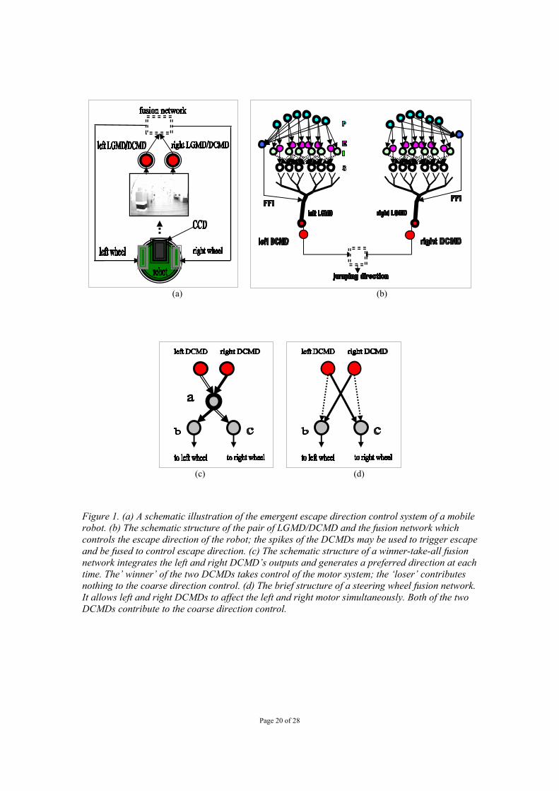
Figure 1. (a) A schematic illustration of the emergent escape direction control system of a mobile robot. (b) The schematic structure of the pair of LGMD/DCMD and the fusion network which controls the escape direction of the robot; the spikes of the DCMDs may be used to trigger escape and be fused to control escape direction. (c) The schematic structure of a winner-take-all fusion network integrates the left and right DCMD’s outputs and generates a preferred direction at each time. The’ winner’ of the two DCMDs takes control of the motor system; the ‘loser’ contributes nothing to the coarse direction control. (d) The brief structure of a steering wheel fusion network. It allows left and right DCMDs to affect the left and right motor simultaneously. Both of the two DCMDs contribute to the coarse direction control.

Page 21 of 28
(a) (b)
20 40 60 80 100 120 140 160 180 200
20
40
60
80
100
120
140
(c) (d)
50 100 150 200 250 300 350
10
20
30
40
(e)
(f) (g)
Figure 2. (a) The Khepera II robot with normal grey scale CCD camera sitting in front of a track, a ball with diameter at 95mm is used in this experiment. (b) An example image from the CCD camera with normal vision. (c) The Khepera II robot with 360 degrees panoramic vision used in the experiments. (d) An example image from the CCD camera with panoramic vision. (e) An example of the transformed images from the panoramic vision camera. The black ball was towards the back of the robot. (f) The defined angles for the robot with normal vision where zero degrees is the front. (g) The defined angles for the robot with panoramic vision where zero degrees is the front.
0◦
Robot
160◦
45◦
+180◦ Robot
0◦ 45◦

Page 22 of 28
0 10 20 30 40 50 60
0.5
0.6
0.7
0.8
0.9
1
frames
exci
tatio
ncylinder approaches from the back
left LGMDright LGMD
(a)
0 10 20 30 40 50 60
0.5
0.6
0.7
0.8
0.9
1
frames
exci
tatio
n
cylinder approaches from the left back
left LGMDright LGMD
(b)
Figure 3. The excitation level, spikes and threshold of the left and right LGMD implemented in the robotic agent’s visual-motor system. Winner-take-all and panoramic vision were used in these examples. (a) A cylinder approached the robot from behind. The right side LGMD reached five spikes early. The robot turned to its left side and moved away to the left. (b) The cylinder approached the robot from behind and to its left. The left LGMD responded early with five successive spikes. The robot turned right and moved away to the right.

Page 23 of 28
0 5 10 15 20 25
-60
-40
-20
0
20
40
ball approaching angle in degree
robo
t esc
apin
g an
gle
in d
egre
e
winner take all without random factor
0 5 10 15 20 25
-60
-40
-20
0
20
40
ball approaching angle in degree
robo
t esc
apin
g an
gle
in d
egre
e
steering wheel without random factor
(a) (b)
0 5 10 15 20 25
-60
-40
-20
0
20
40
ball approaching angle in degree
robo
t esc
apin
g an
gle
in d
egre
e
winner take all with 0.5*rand(1)
0 5 10 15 20 25
-60
-40
-20
0
20
40
ball approaching angle in degree
robo
t esc
apin
g an
gle
in d
egre
e
steering wheel with 0.3*rand(1)
(c) (d)
0 5 10 15 20 25 30
-60
-40
-20
0
20
40
ball approaching angle in degree
robo
t esc
apin
g an
gle
in d
egre
e
winner take all triggered by infrared sensor
0 5 10 15 20 25 30
-60
-40
-20
0
20
40
ball approaching angle in degree
robo
t esc
apin
g an
gle
in d
egre
e
steering wheel triggered by infrared sensor
(e) (f)
Figure 4. The robotic agent escape angle versus ball approach angle with different visual-motor models fusing the spikes from the left and right LGMD/DCMD of the Khepera robot with normal vision. Six trials were conducted per angle in the above experiments. The robot had a normal CCD camera. The escape behaviours were triggered by LGMD/DCMD spikes unless stated otherwise. (a) Winner-take-all model. (b) Steering wheel model. (c). Winner-take-all model with artificially introduced random factor. (d) Steering wheel model with artificially introduced random factor. (e) Winner-take-all model without artificially introduced random factor; the escape behaviour was triggered by infrared sensors. (f) Steering wheel model without artificially introduced random factor, the escape behaviour was triggered by infrared sensors.

Page 24 of 28
-180 -135 -90 -45 0 45 90 135 180-45
-30
-15
0
15
30
45
Ball approach angle in degree
Rob
ot e
scap
e an
gle
in d
egre
eRandomised winner-take-all model
(a) (b)
Figure 5. (a) The escape direction of the robot when challenged with a ball approaching from different angles. Randomised winner-take-all was used to fuse the spikes from the left and right DCMDs of the Khepera II robot. The robot had panoramic vision. Five trials were conducted per angle. (b) Locust jumping directions when challenged with rolling balls approaching at different angles (Santer et. al. 2004)
-100 0 100
-100
0
100
x mm
y m
m
-100 0 100
-100
0
100
x mm
y m
m
(a) (b) (c)
-100 0 100
-100
0
100
x(mm)
y(m
m)
-100 0 100
-100
0
100
x(mm)
y(m
m)
-100 0 100
-100
0
100
x(mm)
y(m
m)
(d) (e) (f)
Figure 6. The escape trajectory of the robotic agent when challenged with a rolling cylinder from 45 degrees, 180 degrees and 160 degrees respectively. Winner-take-all was used in the experiments. Arrows represent the approach direction of the cylinder. (a) A sample image taken during the experiments. The robot was put at the centre of a Cartesian coordinate system with its front aligned to the black arrow at the bottom of the image. The cylinder was covered by irregular textures, such as dots, stripes, and black stickers. (b) The cylinder approaching from 180 degrees behind the robot, model with introduced random factor. (c) The cylinder approaching from 160 degrees, or behind and left of the robot, model with introduced random factor. (d) The cylinder approached from 180 degree, behind the robot, model without random factor. (e) The cylinder approached from 290 degree, or left back of the robot, model without random factor. (f) The cylinder approached from 45 degree, or left front of the robot, model without random factor.

Page 25 of 28
5 10 15
20 25 30
Figure 7. Sample images of the robotic agent escaping from an approaching hand. The number under each image is the frame number. The robotic agent used a pair of LGMD/DCMD to extract visual cues and a steering wheel model to fuse the cues. The escape behaviour was triggered by five successive spikes from a DCMD (right side DCMD apparently). The escape direction was controlled by the steering wheel fusion network. The turning speed is set to 6.4cm/s for left and -6.4cm/s for the right wheel in this experiment.

Page 26 of 28
7.2 7.3 7.4 7.5 7.6 7.70
1 left DCMDright DCMD
15.3 15.4 15.5 15.6 15.7 15.80
1
7.6 7.7 7.8 7.9 8 8.10
1
6.7 6.8 6.9 7 7.1 7.20
1
22.1 22.2 22.3 22.4 22.5 22.60
1
16.8 16.9 17 17.1 17.2 17.30
1
6.3 6.4 6.5 6.6 6.7 6.80
1
52.1 52.2 52.3 52.4 52.5 52.60
1
4.6 4.7 4.8 4.9 5 5.10
1
21 21.1 21.2 21.3 21.4 21.50
1
36.8 36.9 37 37.1 37.2 37.30
1
16.6 16.7 16.8 16.9 17 17.10
1
65.3 65.4 65.5 65.6 65.7 65.80
1
timing of spikes
(a)
Page 27 of 28
0 50 100 150 200 250 300 350-30
-20
-10
0
10
20
30
40
ball approaching angle in degree
locu
sts
jum
ping
dire
ctio
n in
deg
ree
recorded locusts jumping directions
(b)
0 100 200 300 400-30
-20
-10
0
10
20
30
ball approaching angle in degree
locu
sts/
agen
t jum
ping
aw
ay a
ngle
in d
egre
e winner take allreal locust
0 100 200 300 400
-30
-20
-10
0
10
20
30
ball approaching angle in degree
locu
sts/
agen
t jum
ping
aw
ay a
ngle
in d
egre
e
steering wheelreal locust
(c)
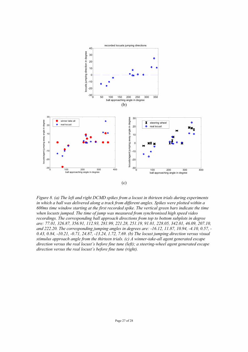
Figure 8. (a) The left and right DCMD spikes from a locust in thirteen trials during experiments in which a ball was delivered along a track from different angles. Spikes were plotted within a 600ms time window starting at the first recorded spike. The vertical green bars indicate the time when locusts jumped. The time of jump was measured from synchronised high speed video recordings. The corresponding ball approach directions from top to bottom subplots in degree are: 77.01, 326.87, 356.91, 112.93, 281.99, 221.28, 251.19, 91.01, 228.05, 342.01, 46.09, 207.10, and 222.20. The corresponding jumping angles in degrees are: -16.12, 11.87, 10.94, -4.10, 0.57, -0.43, 0.84, -10.21, -0.71, 24.87, -13.24, 1.72, 7.69. (b) The locust jumping direction versus visual stimulus approach angle from the thirteen trials. (c) A winner-take-all agent generated escape direction versus the real locust’s before fine tune (left); a steering-wheel agent generated escape direction versus the real locust’s before fine tune (right).
Page 28 of 28
0 100 200 300 400-20
-10
0
10
20
30
ball approaching angle in degree
locu
sts/
agen
t jum
ping
aw
ay a
ngle
in d
egre
e
winner take allreal locust
0 50 100 150 200 250 300 350 400-20
-15
-10
-5
0
5
10
15
20
25
30
ball approaching angle in degreelo
cust
s/ag
ent j
umpi
ng a
way
ang
le in
deg
ree
steering wheel
real locust
(a) (b)
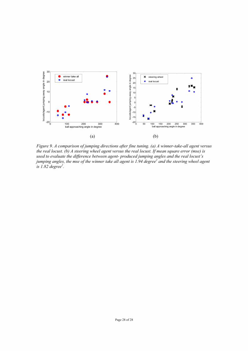
Figure 9. A comparison of jumping directions after fine tuning. (a) A winner-take-all agent versus the real locust. (b) A steering wheel agent versus the real locust. If mean square error (mse) is used to evaluate the difference between agent- produced jumping angles and the real locust’s jumping angles, the mse of the winner take all agent is 1.94 degree2 and the steering wheel agent is 1.82 degree2.