Embed Size (px)
Citation preview

Reaction Mechanisms For Entrained-Flow Coal Gasification
Dr. Stephen NiksaNiksa Energy Associates LLC, Belmont, CA
NETL 2010 Multiphase Flow Science WorkshopMay 5, 2010 Pittsburgh, PA

All Rate Parameters Should Be Assigned From Readily Available Fuel Properties
No connections to testing.
Operating Conditions
Detailed Mechanism
FuelProperties
ParameterEstimation
DVol: AD, ED,V∞
ChOx: AC, EC, nCChGs: {AG,i, EG,i, nG,i}
Predicted Rates and Products
ProcessSimulator

200 ms, S.R.=0.38

There are Six Distinct Stages of Fuel Conversion Chemistry
Devolatilization- Source of all gaseous fuels and soot.- Determines char yield, size, structure, and initial reactivity.
Secondary Volatiles Pyrolysis- Release of noncondensibles at moderate temperatures.- Conversion of tars into soot at high temperatures.
Homogeneous Conversion- Restricted to the gas phase.- Major heat source.- Partial combustion of primary volatiles.- Major source of CO, H2, CO2, and H2O.- Shifting/reforming chemistry throughout.
Heterogeneous Secondary Chemistry- Deposition of coke from gaseous volatiles.- Basis for NO reduction on soot.- Char catalyzed water/gas shifting.
Char/Soot Oxidation- Major heat source.- Determines residual char yield for gasification.- Some flyash production.
Char/Soot Gasification- Determines overall conversion.- Flyash production, via char particle fragmentation + ash agglomeration.

Gasification Chemistry

Accurate Predictions for Devolatilization of Any Coal Type
65 70 75 80 85 90 95 1000
10
20
30
40
50
60
70
AVCO Bomb, 1.3 MPa
Wei
ght L
oss,
daf
wt.
%
Carbon Content, daf wt. %
• Depicts the distinctive yields of individual samples of even the same coal rank.
• Based on only the proximate and ultimate analyses.

Automatically Assign All Parameters In Simple Devolatilization Rate Laws
Even the SFOR matches the FC predictions. Assigned EACT are constant over a broad range of heating rate. Rate laws can be specified for any product, including volatile-N.
0.75 1.00 1.25 1.50 1.75-4
-2
0
2
4
6
hv Bituminous
PFBC1.5 MPa
P.F. Comb.0.1 MPa
EFCG2.5 MPa
ln k
103/T
0 250 500 750 1000 1250 15000
10
20
30
40
50
hv Bituminous
EFCG2.5 MPa
P.F. Comb.0.1 MPa
PFBC1.5 MPa
Weig
ht Lo
ss, d
af wt
. %
Temperature, C

Tar Conversion Mechanism Is Well-Characterized
HC Gases, CO, CO2, H2O
TAR
Peripheral Group Elim.
Char Link Formation
Heteroatom Release
Monomer Decomposition
HC Gases, CO, CO2, H2O
CO, H2, HCN
Oils (BTX+PCX)
+ O2
+ N2 or H2O
+ H2
Soot + HCN
Soot + HCN
CH4 + C2H4+ Oils
+PAH
FC Reaction Sequence + PAH Conversion+ Oils Production (?) Into Soot

OPERATING CONDITIONS: 90.0 micron particles at 25. C are entrained in N2 with 15.0% CO2, 30.0% H2O, 5.0% CO and 5.0% H2 at 1600. C in a furnace at 1600. C for .100E+02 s. The ambient pressure is 2.00 MPa. Primary Pyrolysis Secondary Pyrolysis Products, daf wt.% Products, daf wt.% Soot Fr.= 0.2 0.4 0.6 0.8 1.0 Tar 22.5 18.0 13.5 9.0 4.5 0.0 Soot 0.0 4.1 8.3 12.4 16.5 20.6 H2 1.89 2.17 2.44 2.77 3.16 3.54 CH4 1.6 1.64 1.72 1.45 0.82 0.20 C2H2 0.0 0.00 0.00 0.00 0.00 0.00 C2H4 0.66 0.5 0.4 0.3 0.1 0.0 C2H6 0.16 0.1 0.0 0.0 0.0 0.0 C3H6 0.53 0.3 0.1 0.0 0.0 0.0 C3H8 0.00 0.0 0.0 0.0 0.0 0.0 CO 2.2 2.5 2.9 3.4 4.0 4.7 CO2 3.2 3.2 3.2 3.2 3.2 3.2 H2O 6.1 6.1 6.1 6.1 6.1 6.1 HCN 1.23 1.28 1.34 1.39 1.45 1.50 H2S 0.54 0.56 0.58 0.60 0.62 0.64 Char 59.5 Condensed Product Composition, daf wt.% % C % H % O % N % S Tar 85.6 5.8 7.3 0.94 0.41 Soot 98.7 1.0 0.0 0.34 0.00 Char 99.4 0.5 0.0 0.09 0.00
• Secondary pyrolysis products are accurately predicted from primary products.
• Assume instantaneous conversion for EF conditions.
Coal Soot Yield, daf wt. %
% of Wt. Loss
Pit. #8 22.9 - 29.1 43 – 57 Ill. #6 21.0 40 PRB 9.1 19

Carbon Burnout Kinetics Model for Char Oxidation & Char Gasification CBK includes single-film char combustion, intraparticle
reaction/diffusion, thermal annealing, and ash inhibition. Combustion Gasification
2C+O2 → C(O)+CO C+CO2 ↔ C(O)+COC+C(O)+O2 → C(O)+CO2 C(O) → COC(O) → CO C+H2O ↔ C(O)+H2
C+2H2 → CH4 (slow) CBK/E was validated against a database of 235 independent tests
that characterized 11 coals, 2 coal chars, and a graphite, heating rates approaching 106 °C/s, furnace temperatures to 1527 °C, pressures to 2.0 MPa, and O2 levels to 100 %.
CBK/G was validated against a database of 452 independent tests that characterized 26 coals, heating rates approaching 105 °C/s, furnace temperatures to 1500 °C, pressures to 3.0 MPa, and broad ranges of CO2, H2O, CO, and H2 levels.
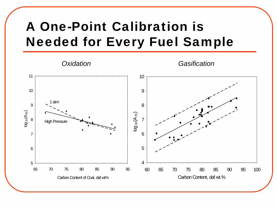
5
6
7
8
9
10
11
65 70 75 80 85 90 95
Carbon Content of Coal, daf wt%
log10
(A30
)
1 atm
High Pressure
4
5
6
7
8
9
10
60 65 70 75 80 85 90 95 100Carbon Content, daf wt.%
log10
(A70
)
Oxidation Gasification
A One-Point Calibration is Needed for Every Fuel Sample

CBK/G Performs Well Over A Broad Domain of Gasification Conditions
0
20
40
60
80
100
120
0 50 100 150 200 250 300 350 400Time, s
Cha
r Con
vers
ion,
daf
wt.%
Gottelborn
Polish
Predicted (curves) and measured (data points) char conversion histories for ( and solid line) Polish and ( and dashed line) Gottelborn chars at 1500°C and 0.1 MPa pure CO2 in a WMR (Moors, 1998).
0.0E+00
5.0E-04
1.0E-03
1.5E-03
2.0E-03
2.5E-03
3.0E-03
3.5E-03
4.0E-03
0.0 0.5 1.0 1.5 2.0 2.5 3.0 3.5PT, MPa
Rat
e, s
-1 H2O
CO2
Predicted (curves) and measured (data points) rates of Xiao Long Tan lignite char gasification at ( and solid line) 850°C in 80 % H2O, 10 % H2, and 10 % CO, and at ( and dashed line) 900°C in 90 % CO2 and 10 CO % (Sha et al., 1990).

• Little literature data on whole syngas; mostly pure CO2 or pure H2O.• SRI can run any H2O/CO2/CO/H2 mixture to 4.0 MPa.• Severe inhibition of steam gasification by H2.• Negligible contribution from CO2 gasification.
Gas Mixture Char Conversion, % 25 % H2O 49.4 +25 % H2 11.2
+25 % H2, 10 % CO2, 40 % CO 12.7
Char Conversion In Whole Syngas

Automatically Assign All Gasification Rate Parameters
0.0
0.1
0.2
0.3
0.4
0.5
0.6
0.7
0.8
0 1 2 3 4 5 6 7 8 9 10Time, s
Par
tial P
ress
ure,
MP
a
0
10
20
30
40
50
60
70
80
90
100
Cha
r Con
vers
ion,
daf
wt.%
Bit. No.1
H2O
CO2
CO H2
CBK/G
Fit
0.0
0.1
0.2
0.3
0.4
0.5
0.6
0.7
0.8
0 1 2 3 4 5 6 7 8 9 10Time, s
Par
tial P
ress
ure,
MP
a
0
10
20
30
40
50
60
70
80
90
100
Cha
r Con
vers
ion,
daf
wt.%
Bit. No.1
H2O
CO2
CO H2
FitCBK/G
The global rate matches the CBK/G predictions for complex mixtures.
The global rate also performs well in modest extrapolations.
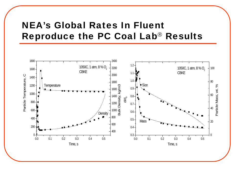
NEA’s Global Rates In Fluent Reproduce the PC Coal Lab Results
0.0 0.1 0.2 0.3 0.4 0.50
200
400
600
800
1000
1200
1400
1600
1800
400
600
800
1000
1200
1400
1600
1800
2000
2200
2400
Density
Temperature
1050C, 1 atm, 8 % O2CBKE
Par
ticle
Tem
pera
ture
, C
Time, s
Bul
k D
ensi
ty, k
g/m
3
0.0 0.1 0.2 0.3 0.4 0.50.3
0.4
0.5
0.6
0.7
0.8
0.9
1.0
1.1
1.2
0
20
40
60
80
100
Size
Mass
1050C, 1 atm, 8 % O2CBKE
d/d 0
Time, s
Par
ticle
Mas
s, w
t. %

Homogeneous Reaction Mechanism
555 reactions, 154 species. Includes C1-C3 GHCs, benzene, toluene,
and phenol. Includes all major IOGs (H2, H2O, CO,
CO2, etc. S- & N-species omitted at this stage. Validated for 275≤T,C≤1425;
1≤P,atm≤42; and 0.65≤S.R.≤3.30

PSDF Consistency Check
Data on PRB subbituminous & HWA bituminous- Impose the actual S.R., T, P, H2O/Coal, &
O2/Coal
Abundant CH4 in the product gas
Predicted CO & H2 too low; H2O too high but closer to equilibrium
Correct tendencies among these cases with variation in•O2/Coal & H2O/Coal
PRB/O2
0.6 O2/Coal0.5 H2O/Coal
972 0C1.5 MPa
0
10
20
30
40
50
60
70
80
H2O CO H2 CO2 CH4
Mol
e %
EquilibriumPSDF DataMechanism
PRB/Air0.8 O2/Coal
0.4 H2O/Coal
952 0C1.5 MPa
0
10
20
30
40
50
60
70
80
H2O CO H2 CO2 CH4
Mol
e %
PRB/Air1.2 O2/Coal
1.9 H2O/Coal
957 0C1.5 MPa
0
10
20
30
40
50
60
70
80
H2O CO H2 CO2 CH4
Mol
e %

1D Gasifier Simulation With Detailed Ignition Chemistry & Equilibrated Syngas Composition
First-stage calculation based on full kinetics to determine Xchar and Xsoot.
Steam injection into a reducing second stage.
Equilibrium gas compositions shift throughout the second stage.
Steam gasification with strong CO inhibition.
Soot persists.
0 5 10 15 20 25 30 35Time, s
0
10
20
30
40
50
60
70
80
Maj
or P
rodu
cts,
daf
wt.%
CO
H2O
CO2
H2
Soot
0
20
40
60
80
100
120
140
160
180
0 0.02 0.04 0.06 0.08 0.1
Maj
or P
rodu
cts,
daf
wt.%
hv bituminous
O2
Char

NEA’s ChemNet Post-Processing (CNPP)
CFDFlowfieldT-FieldMajor Species
NOX Post-Processor
NOX Predictions
NOX, LOI
PredictionsCFD
FlowfieldT-FieldDTURBConserved Scalars
ChemNetPost-Processor
Equivalent Reactor Network
Detailed Chemistry
Calculations
Cantera
PC COAL LAB
ConventionalPost-Processing
ChemNetPost-Processing

Severe Implementation Obstacles for CFD
Solvers do not handle irreversible chemistry with radiation & particle dynamics.
Only a handful of species can be included.
Fluent v.5.5 could not converge a 2D axisymmetric coal-flow with this chemistry.
Coal → Vol + Char (R.1)
Vol → νCH4CH4 + νC2H2C2H2 + νH2H2 + νCOCO +
νCO2CO2 + νSOOTSoot + νH2OH2O + νN2N2 + νS2S2 (R.2)
CH4 + 0.5 O2 → CO + 2 H2 (R.3)
C2H2 + O2 → 2 CO + H2 (R.4)
H2 + 0.5 O2 ↔ H2O (R.5)
CO + 0.5 O2 ↔ CO2 (R.6)
Soot + 14 O2 → 25 CO + 3 H2O (R.7)
Char + 0.5 O2 → CO (R.8)

Summary Accurately predict devolatilization behavior based on
prox/ult analyses without lab support. After a 1-point calibration, CBK accurately predicts
oxidation and gasification of char & soot for diverse conditions.
Comprehensive mechanisms automatically specify all parameters in global rate laws.
Difficult to implement even a skeletal gasification mechanism in CFD.

Forget “Understanding” and Focus On Accuracy in Applications
Fuel Science SHOULD specify all the rate parameters used in process simulations (CFD, AspenPlus, HySys, etc.)
Simulation practitioners should NOT have to comb literature or resort to default values.

Multifuels Capability Requires Detailed Volatiles Compositions
SD SG JR GL PR JW Volatiles, daf wt. %
Wt. Loss 86.1 86.0 65.2 56.5 59.8 39.7 Soot 4.3 13.4 30.1 33.7 37.9 26.8 CH4 7.1 7.4 0.7 0.4 0.5 0.3 C2H2 2.2 1.3 1.5 1.0 1.3 2.3 C2H4 1.4 1.5 0.0 0.0 0.0 0.0 H2 2.1 1.7 3.4 3.6 4.0 3.5 CO 48.4 41.5 12.9 7.2 6.1 1.7 CO2 8.2 8.0 6.4 2.2 1.7 1.0 H2O 12.1 7.7 7.6 4.9 4.3 1.8 HCN 0.0 0.0 1.26 2.47 2.24 1.52 NH3 0.24 2.90 0.0 0.0 0.0 0.0 H2S 0.0 0.44 0.42 1.17 1.91 0.96
Char Comp., daf wt. % C 94.7 97.1 98.9 98.4 98.5 98.2 H 3.4 2.5 0.5 0.5 0.4 0.5 O 1.9 0.4 0.0 0.0 0.0 0.0 N 0.0 0.0 0.4 1.1 1.0 1.26 S 0.0 0.0 0.1 0.1 0.1 0.0
Char ash, wt. % 2.5 75.7 15.9 14.2 30.9 21.8 Char size, µm 97.6 103.6 29.9 59.1 54.1 41.7
Biomass has:• Higher volatile yields.• Less soot and H2. • More HCs and CO. • No char-N.• Larger char sizes.• SG also produces
abundant NH3 and a very high char ash content.