Embed Size (px)
Citation preview
RDTR No. 170I September 1970
I
Conversion
ofHobart Model C-100 Electric Mixer to Air Drive
for
Use In Mixing Pyrotechnic Compositions
*4
AJ
,DC
Q*Pmodc., hyNATIONAL TECHNICAL 4INFORMATION SERVICE lii'
PREPARED BY )RESEARCH & DEVELOPMENT DEPARTMENT
Naval Ammunition Depot, Crane, Indiana
33
-l
dC

NAVAJ, AMMIUNITION DEPOTCrane, Indiana 47522
RI)TR ,No. 1701 September 1970
CONVERSION OF HGBART MODEL C-100ELECMRIC MIXER TO AIR DRIVE FOR USE IN
MIXING PYROTECHNIC CXI4POSITIONS
BY
PATRICK L. ARVIN
and
9EI4AN E. DARE
This report was reviewed for adequacy and ted inical accuracy byRobert E. Sloan, Mehanical Engineer.
Released
S. M. FA.SG, birect.r
Research and Develoment Departnc

RDTR No. 170
TABLE OF CCnWS
I. Introduction ... . . . . . . . . . . 1
II. Material Required ......... ........... 1
III. Removal of the Electric Motor and Electrical Components . 2
IV. Modification of Rotor Assembly ... .............. .3
V. Modification of Gast Air Motor Model 6.A-NRV-11 . . ... 4
VI. Assembly of the Air Motor to the Mixer .... .......... 4
VII. The Gast Air Motor ......... . ............ 6A. OperationB. Performance
VIII. Lnstructions foi Operation and Care of the Model C-100Hobart Mixerwith Gast Air Motor. ...... ..... 8
Figure 1. Motor Housing ................... .11
Figure 2. Base and Pedestal Unit. ........ ....... 12
Figure 3. Transmission Case Unit. ............... 13
Figure 4. Performance Data-Air Motor. ............ . 14
Figure S. Air Motor Selection art .............. 15
Figure 6. Installation Diagram .. .. .. .. .. .. .. . .. I16
Figur2 7o Graph--Agitator Speed vs Air Motor Speed. . . . . .. 17
RDC-3-250 - Shaft, 11obart Model C-100 Mixer, Modified
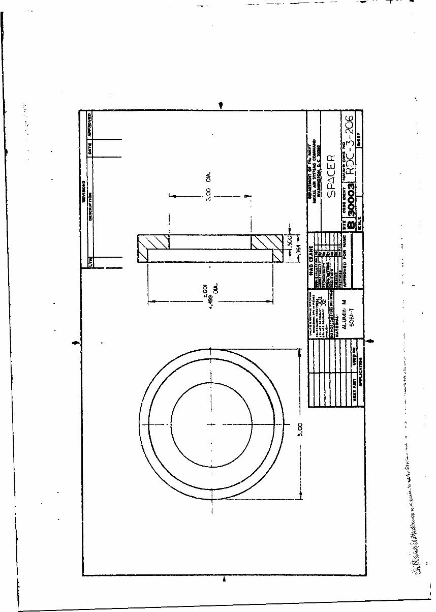
FJ)C-3-206 - Spacer
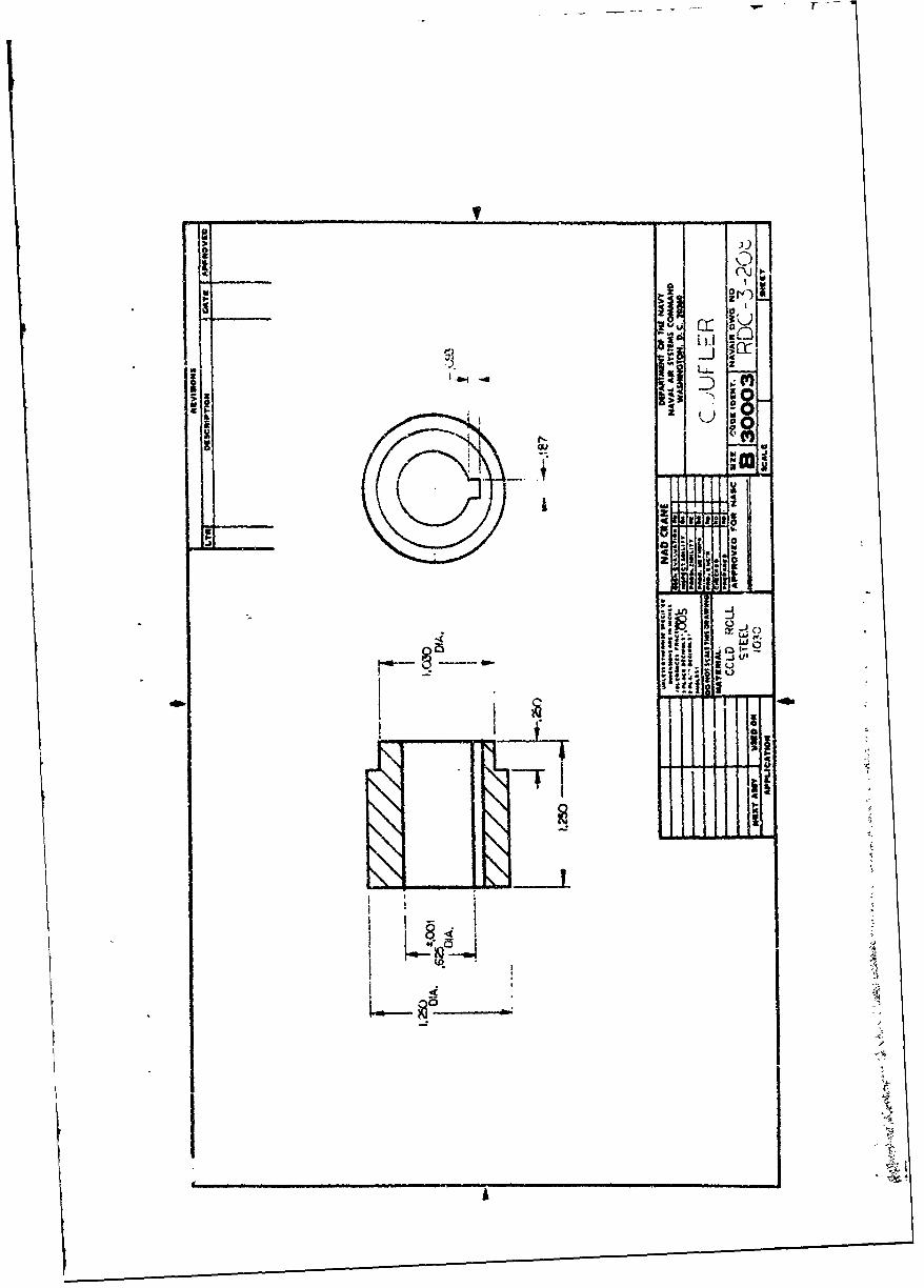
RDC-3-208 - Coupler
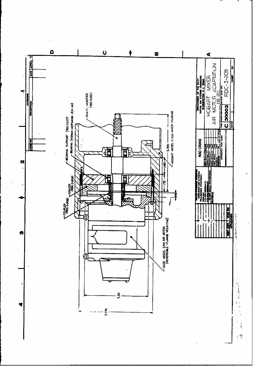
RDC-3-209 - Hobart Mixer Air Motor Adaptation (10 Qt)
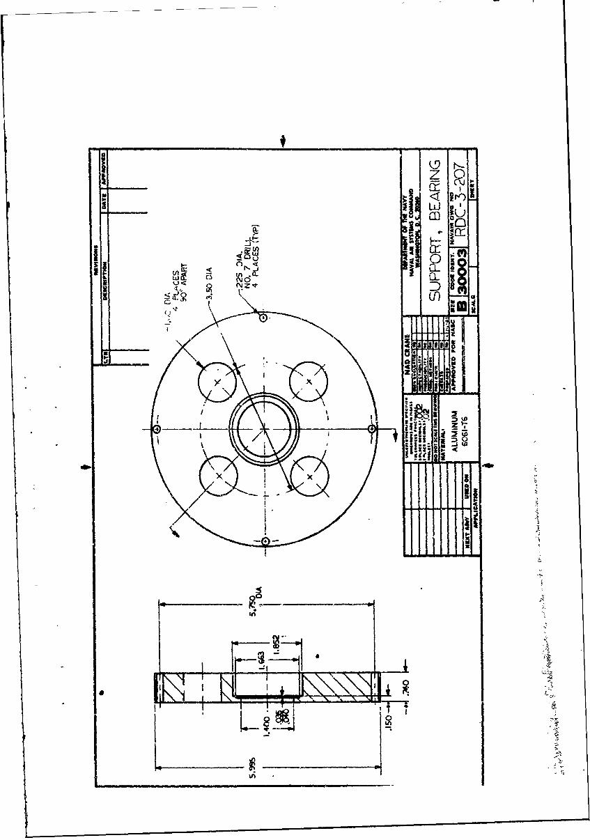
RDC-3-207 - &uport, Bearing
i . . .. . .. .. . .. . .. . .. . .. .. . .. . .. i

RD.R No. 170
1. INTROWCTION
A. During development of a Catalyst Geneiator at Naval Annunition
Depot, Crane, Ind.ana, a special need arose for a somewhat tmiversal
mixer to thoroughly blend pyrotechnic mixes of various types under
special conditions.
The search for a mixer which could be used to mix these pyro-
technic mixes of approximately 10 lbs. in size, ,n a reproducible as
well as a productive basis led to the NLxlel C-100 (Planetary Action)
Mixer manufactured by the Hobart Manufacturing Company, Troy, Ohio.
B. Preliminary testing of this mixer, with its planetary
action, proved that it could meet the criteria already aentioned.
One problem remained however, the Model C-lhO Mixer is equipped from
the factory with the standard tyT- electrica:; motor and related
equipment which would not perit the Model C-190 to be used to mix
pyrotechnic mixes because of safety rer'uirements.
Since this mixer pravidcd the proper mixing action, it was
suggested that the electrical motor and related controls (switches)
be replaced with an air motor z-. adapt this mixei, tc meet the safety
requirements involved.
Th following is a description of how the tW-del C-lOG Mixer
was converted from electrically to air driven paer.
11. IEUA RE]QUU ;
A. :bbart Model C-100 Mixer (with or without electrical motor).
If the mixer is without the KFB-C-IO0 motor, Hobart Part No.
P-22275-86 (Rotor Assembly) #ill also be needed. Tnis should in-
clude the grease deflector (M-62489) and ball bearing (BB-16-1).
41

RDTR No. 170
B. Gast Air Mctor Model 6WI-NRU-1l (flange mounting)
C. Bearing (Norma--offta 204-K) - .7874 in&. I.D., 1.8504inch O.D. LINo required - one should come with mixer)
D. Bearing Support (RDC-3-207)
E. Spacer (RDC-3-206)
F. Coupler (RDC-3-208)
G. 3/16" square key - length as required
H. Screw-Round Head #8-32 x 2 1/4" long (4 required)
I. Washer for #8 screw (4 required)
III. REM)VAL OF THE ELIECRIC MIIOR AND ELECIRICAL CMJI'S
A. First remove the back bearing bracket. Part of the centri-
fugal switch will stay intact with. this bracket (see Figure 1).
Next remove the two wires from tis part of the centrifugal switch.
The rotor assembly is now ready to be extracted. This is done by
pulling directly out wile slowly turning the agitator shaft on the
mixer. This assembly will include the rotor, shaft, ball bearing,
grease deflector, won, gear, and part of the centrifugal starting
switch (see Figure 1). Now remove thz data plate on the back of the
mixer (Part #18 - Figure 2). "Tis permits access to the capacitor
which is mmted inside. Disconnect the two wires from the capacitor
and rezm-ve the capacitor and capacitor bracket. The two wires
removed from the capacitor can now be pulled up into the motor
housing to the stator assembly. Next disconnect the two wires
from the plug-in cord. One wire is located at the manual switch
(Part #15 - Figure 3) on the side of the machine next to the gear
selector. This necessitates the -emval of the shifter handlv.
2 -

RDTR No. 170
Mtile the switch plate is off, &isconnect the two wires and remove
the switch. Also remove the ground wire from the housing inside.
The other wire from the input cord is connected to the
stator. With this wire disconnected the stator is ready to be
removed. Four studs on the outer perifer" bf the stator which held
the back bearing plate are all that secures the stator. With these
studs removed the stator can be removed by pulling directly out
while tapping on the housing.
The only thing remaining to be removed is the input cord.
Remove the fiber bushing and strain relief from the cord and pull
the cord out through the hole in the housing.
IV. MODIFICATION OF ROTOR SSE BLY
A. he shaft of the rotor assembly which was extracted from the
rixer must he modified to comply with Drawing No. RDC-3-250. This
assembly includes the rorh_, shaft, ball bearing, grease deflector,
worm gear, and part of the centrifugal startrig switch (see Figure 1).
The rotor and the centrifugal switch zumst be pressed off the shaft,
This my be done with or without the bearing and grease deflector
in place on the shaft. Care should be taken so that the worm
gear, bearing, grease deflector, and shaft are not dwraged in this
process. With the rotor and centrifuga) sw_-ch off of the shaft,
the shaft can be chucked in a lathe and modified.
3
RijfR No. 170
V. MODIFICATION OF GAST AIR MOTOR MODEL 6AM-NRV-1I
A. Modification of Gast Air Motor requires disassembly of
the motor. The shaft must be shortened to comply with the .418
inch dimension appearing on Dwg. No. RDC-3-209. This requires
measurement of the shaft extension before disassembly. This
should comply with the drawing included with the performance data
given which is supplied by the Gas t Manufacturing Company. The
keyway on this shaft must now lue cut another .50 inches toward the
rotor.
With the air motor apart, the front mounting flange can be
modified. This requires that the ouside diameter of 6 1/2 inches
be machined down to a diameter of 5.995 inches, the same as the
outside diameter of the bearing support (ROC-3-207). This permits
entry into the mixer housing. The flange must also be faced to a
thickness of .400 inches as seen in Dwg. No. RDC-3-209. This leaves
a flat surface for the four mounting screws to secure the assembly.
VI. ASSSIBLY OF 8E AIR MOTOR TO ThE MIXER
A. First of all, press the ball bearing and grease deflctor,
it removed, back onto "ie modified worm gear shaft ip the same
position as previously occupied. Next, press a second ball bearing
(Norma-foffmann 204-X(K) in appropriate position into the bearing
support (JIfC-3 207) as shown in Thg. No. RDC-3-209, This bearing
and bearing stqport can now be pressed onto the other end of the
4-'

RDTR No. 170
modified worm gear shaft. Only light pressure should be required
to press either bearing into position. This assembly which should
include the worn gear shaft, two ball bearings, the grease deilector,
and the bearing support is ready for insertion into the mixer
housing.
To insure proper position of the four outer holes in the
bearing support, the studs which held the old stator assembly may
be used for proper alignment. Turning of the agitator shaft on the
ixer during insertion of the worm gear asseikly helps draw the
asserily firmly into place. Inspection through the hole by the
shifter handle insures proper seating of the bearing support and
also the inner bearing. The 3/16" square key aid coupler (RIDC-3-208)
can now be added to the worm gear shaft with the relieved end out-
ward (see RDC-3-209).
Next, the spacer (RDC-3-206) can be pressed onto the modified
Gast Air Motr, as shown in lwg. No. RDC-3-209. This need not be
a press fit but the press fit helps to hold the assembly in place
and insures proper positioning of the spacer in the final assembly.
This air motor and spacer assembly is now ready for insertion -. Ito
the mixer housing against the bearing support. The key-ways wist
be lined up prior to insertion by tu..rig either of the two shafts.
Sharp edges should be filed ard m y be filed to a sligj. taper to
ease alignment. The four aligment studs may now be replaced by
four 2 114 inch. #8-32 rotwd head screw udh fa't wasihrs. TWse
four screws will secure the entire assembly (see RDC-3-209).
5"

RDITR No. 170
VII. T GASr AIR IH)ORt
A. Operation
The Gast Air Motor can be used in any position providing
adequate lubricatioL is administered through an air line oiler
and end thrust is kept to absolute minimum. For best results,
assemble the air motor so that the inlet and exhaust ports are on
top since this is where the oilers are for intermittent operation
of the air motor. For continuous operation, the air line oiler
must be used. Gast Manufacturing Company recomends use of their
accessories for the Model 6AM Air Motor for longer life, proper
operation, and dependability. These accessories include filter,
regulator, lubricator, and lubricating oil, part numbers 4F103,
4ROOG, 4L002, and AD220, respectively.
For moderate speeds (under 2,000 r.p.m.) or intermittent
operation, 1 squirt of oil in bearing oilers per day will suffice.
If the duty is continuous or speed is high, use an automatic air
line oiler set to feed 1-3 drops per minute. The bearings will
receive oil from the rotor chamber duri.g autcmiatic oiling.
Lubrication is necessary for the bearings, shaft seals, and rust
prevention. Excessive moisture in the air line can cause rust
formation in motor and :Ydght also cause ice to fonn on muffler due
to expansion of air through the !,.tor. The 'moisture problem can
be corrected by installing a moisture separator in the line and also
hv __! . a4trccu'r IeLween the coaressor and air receiver.
6

II11 11 . 1711
If the motor is sluggish or inefficient, try flushing with kerosene
in well ventilated area. Disconnect the air line and muffler and add
several teaspoonsful ol kerosene. Rotate the shaft by hand in both
directions for a few minutes, again connect the air line and apply
pressure slowly until there is no trace of kerosene in exhaust air.
(Keep face away from exhaust air) Check the muffler felts for grease,
dirt, etc. If dirty, wash them ix, solvent. Replace the fel i and
connect the muffler. Relubricate the motor with a squirt of oil in
the chamber and bearing oilers.
B. Performance
The speed of the air motor can be easily adjusted to
operate from 300 to 3000 rpm. The Gast Model 641 delivers up to
3 horsepower, as seen on the performance data sheet. This provides
more than enough power to mix most pyrotechnic mixes since it re-
places a 1/4 horsepower electrical motor previously in the mixer.
Certain characteristics should be known about the air motor; however.
(1) Horsepower of an air motor is relative to R1M d
to air line pressure.
(2) An air motor siows down :-ien load increases at the
same time its, torque increases to a point where it matcies the
load. It will continue to provide increased torque all tbe way to
stall condition. It can maintain the stalled condition without
any harm to the motor.
7

RiTJR No. 170
(3) Av the load is reduced, an air motor will increase
speed and the torque will dec-ease to match the reduced load.
(4) When the lad on an air motor is either increased
or decreased, sped can be controlled by increasing or decreasing
air pressure.
(5) Starting torque of an air motor is lower than
runng torque. While this provides smooth, no-shock starting, it
is necessary to have additional airline pressure for starting
under heavy loads.
- (6) Air consumption increases as speed and air pressureare increased.
(7) It's simple to change horsepower and speed of anair motor by throttling the air inlet. Therefore, the best rule
of tub for selecting an air motor is to choose one that will
provide the horsepower and torque required using only 2/3 of the
line pressuire available. The full airline pressure will then be'
available for overloads and starting.
This explains why the Model 6AM Air Motor was chosen to
replace the low horsepower electric motor. The next smaller model
is the 4AM which develops less than 1/4 horsepower at 300 RPM,
as can be seen from the air motor selection chart.
VIII, I IONS FOR OPERATION AND CARE OF THE mODWL C-IOQ HOBATw
MIXER WITH GAST AIR MMOR
A. As before with the electrical motor, the air motor must be
stopped to shift the mixer to a different e to yrcv-nt damage
81

RU-TM No. 170
to the gears in the mixer.
B. The transmission gearing is packed with a special grease
that will last for several years. gr ase is needed for re-
placement, it should be ordered from the Hobart Manufacturing
Campany. Lubrirate the bowl slideways occasionally by applying
a very small amount of oil with the tip of your finger. Only
mneral oils are suitable for this type of lubrication. The
polished drip cup is a safe-guard to prevent any lubricant that
migit work out of the planetary gearing 'rom dropping into the bowl.
Take off the drip cup (by removing the two screws) periodically and
wipe it clean.
C. To raiss the bowl, pull the long lever on the side of the
mixer down until it catches in the detent hich holds it in
position. It is necessary to lower the bowl in order to change
agitators and also makes the bowl more accessible f-,r filling,
D. The replaced electric motor was operated at a speed of -A1725 RPM. This gave the mixer three positive speeds for the
agitator. These three speeds are as follows: 34
(GEAR) (AGITATOR SPEED)
LOW 144 RR4 'A
Intermediate 258 RIM-
High 450 R?!
Te mixer now has a wide range of speeds since the air motor speed
can be varied. Caution should be taken not to exceed the engi- -"
neered design limits of the mixer. With the wide er- - ,0 u""'"..
94

H(111 No0. 170
of speeds for the agitator, there should be no reason to exceed
the speed of the electrical motor, 1725 RM4, which was replaced.
The graph of agtator speed vs air motor speed shows this speed
range. As noted, this agitator speed does not include the plane-
tary action of the agitator.
t -
)IiI
I
-,A
10
I,
MOTORREPACEMENT PAMT
8 0 116 1810 1 14.15 17 19 20 21 22
TYPe Of Motir -KFB-C-100 Motor ML l634l-ABC,L,M1"istar type and PC nwee~r are st~ *emo'vtor CiouetfreS under nw* plate).
When ordering motor replacement parts, in addition to motor Type and ML No., giveSerial No., Model. ML, and all electrical data shown on machine name plate.
Ubae. PartNO. NO. Name of Part Amt.
1 b9-74268-1 Switch - Starting (Stationary Part)------------------------ 12 R-20647-2 B~racket - B~earing-----------------------------------3 34-75437 Insulator - Starting Switch------------------------------ 14 SL-Z.2 Luading Spring - N. D. *S.12 ----------------------------- 25 88-16-1 BAU Bearing - N. D. OC37011---------------------------- I6 SC-9-70 1ac0. Screw - 06-32 /~ 1/4" Rd. Hd.------------------------ 27 NS-9-12 M~ach. Nut - 08-32 Hex--------------------------------- 48 WL-7-6 Lock Washer - *8 Ext. Shakeproot ------------------------ 49 M-61671 Stetor Stud - *8-32 .% 4-5/8- 14. -------------------------- 410 NS-9-12 Mach. Nut - 08-32 Hex ---------------------- 411 WS.2.1S Washer --------------------------------------------- 412 P-65477-12-1 Stator Assy.(115V. .60 Cy.. I Ph. )(ltemn '1 not included) --13 P-fl'?7-12-2 Stator Assy. 11206V. .6. Cy.. .1 P:h. (ttem *I not i.-7uded) ---- 1U4 P-55477-12. 3 Stator Assy.;V'., 6' (y.. I t . 91'en. -'t nc icded) ---- 1is P-95477-13-1 Stator Assy.(115V..50 Cy.. I Ph.Ilte-n *I not it-cluded) --- I16 P-65477-13-2 Stator Assy. (220V..* 50 Cy. . I Ph. Xylem #1 not included) -17 P-22275-96 Rotor Assy. (60 Cy. )------------------- ---------------- 1Iis P-22275-87 Rotor Assy. (50 Cy. ) ------------------- ---------------- 1I111 R-67500-20 O*Rind.............. ------- ----------20 -1-1 Sall Bearln .D. OZ99504 ---------------------------
21 Is5289 Ocleto Geae -------------------------------2 2 P -e 8 7 7 C a a u t r ----------------------------

C-'0 REPLACEMENT PARTS
13
12 -~17
10
k "-.9 . 26-21"
7 j 't 285
7. I
ILIU.. PART
6 2r4
-- t7
BASE AND PEDESTAL U?~1T
ILLUS. PARTPL-$481 NO, NAME OF PART ANT.
I SC-W27 Fin. Bolt - 5116"-18 x 11 Hex T4 ...----------------------------------- 42 W/-44 Lock Washer - 5/16" x .125" x .07-.. . . . ..------------------------ 43 P-4W0? Screen - Air --------------------------------------------------------- 14 T-6100-1 B& ... ------------------------------------------------------------- I5 SC-40-51 Cap Screw - *8-32 ) 1/2" Soc. Fil. Hd . . ...------------------------ 8$ P-6163-1 Slideway - Left Hand ------------.--------------------------------- 17 P41635 Apron .---------------------------------.............................. 1I S-9-93 Miach. Screw - $6-32 x 1/4" Rd. Hd .-------------------------------- 49 SC-7-23 Mach. Screw - *6-32 x 3/8" Rd. Hd .--------------------------------
10 3-61669 Block - Apron ------------------------.-----------------------------22 T416834 Pedestal------------------------------------------..- -1
12 WI,.4-2 Lock Washer - 3/8" x .136" x .070" --------------------------------- 213 SC-36-57 Fin. Brt - 3/8"-16 x 1-1/4" Hex Hd ..--------------------------------- 214 SC-7-41 Mac1-. Screw - 632 x 3/8" Rd. Hd ....................------------ 115 VI.3-15 LocI. Waoher - *8 x .041" x .031" -----------------------------------16 M-41949 Spring - Bowl Lift Detent -----.------------------------------------- 217 P-11800-88 Dowel---------------------------------------------------------- 218 B-103012 Plate - Mach. Drta 4 Back Cover (Give serial No. & elec. spec.) -------- 119 SU-12-26 Mach. acrew - 96-12 x 1/4" Bind. Hd .------------------------------ 420 M-20334 Bracket - Capacitor (60 Cy.) ----------------------------------------- 121 U.21227 Bracket - Capacitor (50 Cy.) ----------------------------------- - I22 M.64228 Support - Capacitor Bracket ---------------------------------------- 123 SC-15-36 Mach, Screw - *10-24 x 5/" Oval Rd .------------------------------ 224 NS-4-21 Mach. Nut - If0-24 Hex --------------------------------------------- 2.o5 F -fel- ., , ,. .. ... - R, . 7.& -'£ n ----------------------------------------------- 221 SC-47-71 Set Screw - 26-32 x 1/8" Soc. Hdls. Flat Pt.-------------------------- 227 SC-5y-15 Set Screw - 3/8"-26 x 5/8" Hdli. Cup Pt.. . ..---------------------- . 4
FIGE91 2 -_ _-
12

C-100 REPLACEMENT PART
,2e j, iz7-28-2
7 919 20
54 P.-548a1
TRANSMSSION CASE UNITILLUS. PARTPL.".82 NO. NAME OF PART AMT.
I M-4VA64 Square Dri've Shaft & Zerol Bvel Gear Assy. (23T) ------------------ 12 SC-40-33 Cap Screw - #20-21 x '183 Sot. Fil. Ha . ---------------------------- 3S Wl-3-23 Lock Washer- '10 x .070- x .056 ---------------------------------- 3
4 3-61W Cover - Attachment Hub ------------------------------------------5 P41631 Hub - Attachment --------------------------------------------------- 15 1-50 Thumb Screw ---------------------------------------------- ---------- II -47500-20 "O Ring ------------------------------------------------------------ 1a M-6'"7 Washer - Thru:ft ---------------------------------------------------- I9 142628 Gear C,.se, Dowel & Bushing Sub-Assy. (mdcls. !:-ms 010 & 13) ------ I
10 P.118004- Dowel ----------------------------------------------------------------- 111 R-12#30-3 Key ---------. . ..------------------------------------------------------ 112 1-4163 Roo - Shifter --------------------------------------------------------- 113 1-467/2 Bushing (Fiber) ------. ..---------------------------------------------1i R-5 0- "0" Ring ------------------------------------------------------------- 11 S41870 Switch -----------------.------------------------------- ------------ I16 RR-4-4 RetaIning Ring ----------------------------------------------------- I17 B-02976 Plate - Switch -------------------.----------------------------------18 SC-S-37 Mach. Screw - f3-48 x 214' Rd. Rd ..-------------------------------- 21t PG-3-32 Groov-PIn - Tyre 1. 2/$" x 3/4 - -------------------------- ------- I20 M41b77 Hardle - Shifter ---------------------------------------------------- .21 SC-IS-S Macb Screw - "-32 x 1/4" Oval Hd. --------------------------------- 422 F"B4-21- Strain Relief (For item *2) ---------------------------------------- 123 FE,-6-16 Strain Relief (For item 926) ---------------------------------------- 124 FF,-32 Strain Relel (For itens #27 & = ---------------------------------- I25 843335-12 Cord & Plug (2 Cond. Undo. 125 V.) -------------------------------- 126 S-6333-17 Cord & Plug (2 Cond, 20r&:50 V.) -----------------------------------27 .,-6333,-30 Cord & Plug (3 Co.nd. Under 150 V.) (Ground) ------------------------28 S-6333343 Cord & Plug (3 Cond., 2C0-250 V.) (Ground) --.--------------------- 121 R448994 Cord - Export ------------.-------------- -------------------------- 130 M-61672 Bushinqg (Flber) --------------------------------.-------------------31 P- tl34 Cover - Bearing Bracket ------------------------------------------- 132 SC-O-1 Macb. Screw - ,10-24 x 31?,' Trusc Rd .-------------------------------- 133 .-.-.. Motor (ee separate Motor Parts Sheet) -----------------------
FIG. 313

MODEL - __________-__
6AM P.; 2%~3- -
AIR MOTORFer',1,ce Dr!- Deliver$ up to 3hp. Spfdmay be varied iIrm 300 to 3000 rpm; hip isrelative to rpm. Maximum recommended op.912611i1 Wessute-100 psi. Performince ciervesshown are for reversible mondels. Air cofliurrnp-tion curves will be slightly lower for siigle
4 12
Za Ua I_
-- Tp-' rj *
I go ICi ISM.2....................1..0....M.JISPEED IN~ Al SPE I P
it ~10 JI
94 S
...... ~ ~ .4SPEED ;N RPM
FIROME 4

AIR MOTOR SELECTION CPART
These are close al proxim0ons.
8. Performance c.'-ves. dimensionai -drawings. xcessores and ordering
?.A information fo. each model are ---
provided on the following pages. --. -
50 -a -O - | - -p
-- .
| ,--.,-I.o-$tt r t 10 80IIs
.e - - - - -/ -.
-- | -<, +
l - , _ _
--- - . - -;, - - .
411
St1
'IVSA
/ Arl~2iM 2:A StTlt I"U 2000 250
FLOURY 5
U.I5A

C-0 00 INSTALLATION
- _i¢hi
INSTA TION DIAGRAM
FIGUREE 6
16

K-. . .........
, -- - -*
S* .77
NAo -V--. .i.. ..
. L k.
' '- -
~ 77~ :~]::77~77 ~ j77
Eli-
0 -
I - 1 ".
- Ix : : .- -i .\ x i" :.
,- , = . . . .!. ... . I \' " N! " I.
- .. . . , . .- . ,D \I
.. . .. , .. , .....-.
,i +.i>. . .+ . . . - . - .. <. ' -.. . . . . ... .. *..
,,.° ++.I, . ... t. . I., \ I
gg
rjjtjj(Ir
LDF
~~IL
JA
a I.
II
fi ii C)
. ... Cr
Ai i i 1
zo
II L--J 1c r
LL
c~cn
C;U
LII
- -- T
V
g
wJ
li
-- b 4 -O
C54
low
cr)
II
DOCUMENT CONTROL DATA- R & DN..t.,, , .I.,.., I t. ... l d 1.. I .,. I t., s ...d mtcd,.n.' ..l....oftwl n l e .,elt¢. *h-11h te 1110 -W!1 rttporl A C l,, 'hed)
I OIf€.. NA I9N. 46C 7,'VI-I ( . l,.|lC -,#h.-) 20, 16'(CRNT SECURl TV CL AI SIF I, ATION
Naval Ammunition Depot UNCLASSIFIEDCrane, Indiana 475222,0
3 REPO"T ,lTLE
Conversion of Hobart Model C-100 Electric Mixer to Air Drive for Use in MxingPyrotechnic Compositions
4 OC SCfIPTIVC NOTES (T'ype of tcport and InclusivI data.)
s AU T"ONI$m rIs*t aI. middle Iflttel. lost name)
Patrick L. ArvinSherman E. pare
S. REPORT OATE T. TOTSL NO. Or PAGC$ Tb. NO fte Al'S
I September 1970 22 088. CONTA.CT OR GRAANT N.O . OAIGINATOR*S REPORT NWU*OCERISI
b. PROJECT NO RM No. 170
C. Sb. OT"ERt REPORT NO(SP iAny w*1 r n,,mbore thnt soy be *sIl.edthis repol)
d.
30 OIOTRISUTION STATIMENT
Distribution of this document is unlimited.
II. SUPPLEMENTARY NO tIES 1 "' SP ONSORINGO ILITARY ACTIVITY
.3. AGSTRACT
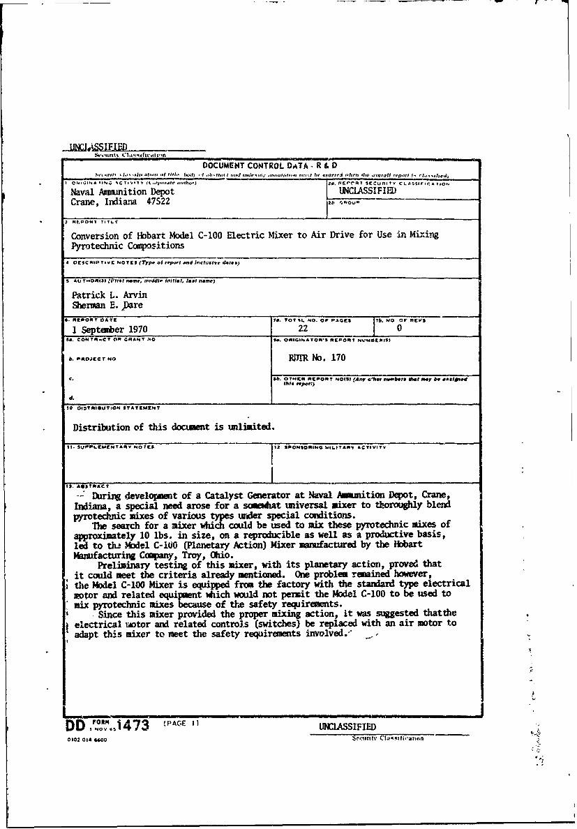
-- During 4evelopmeat of a Catalyst Generator at Naval Ammition Depot, Crane,Indiana, a special need arose for a somewhat universal Mixer to thoroughly blendpyrotechnic mixes of various types under special conditions.
nw search for a mixer which could be used to mix these pyrotechnic mixes ofapproximately 10 lbs. in size, on a reproducible as well as a productive basis,led to th- Model C-IO0 (Planetary Action) Mixer manumfactured by the HobartMaufacturing Copany, Troy, Ohio.
Preliminary testing of this Mixer, with its planetary action, proved thatit could meet the criteria already mentioned. One problem remained however,the Model C-lO0 Mixer is equipped from the factory with the standard type electricalmotor and related equipment which would not permit the Model C-100 to be used tomix pyrotechnic mixes because of thie safety requirements.
Since this mixer provided the proper mixing action, it was suggested thattheelectrical motor and related controls (switches) be replaced with an air motor toadapt this mixer to meet the safety requirements involved., '
D-O 1473 - ' . .......DD: NV%, 1 47 AGE Ia UNnASSIFIED0 102 04 "00"
Se urity CtM, Rifieaton
LIPNA A LMA 93 LiN' C9FV WORD$
POLE WI ROLE Wt 14OLI WY
Hobart Model C-100 MixerCentrifugal Switc
AgitatorMotor HbusingStator AssemblyRotor AssemblyGast Air Motor Model 641-NVr-11Bearing SupportEnd ThrustPyrotechnic MixesMixerAir PressureStarting TorqueAir ConsumptionPlanetary GearingPositive Speeds
DD ,)ovi.1473 ,Tc.:i Lzcssc(PAGE 2) Security C18251fifctlan