Embed Size (px)
Citation preview

RDMA over Commodity Ethernet at Scale
Chuanxiong Guo, Haitao Wu, Zhong Deng, Gaurav Soni,Jianxi Ye, Jitendra Padhye, Marina Lipshteyn
Microsoft{chguo, hwu, zdeng, gasoni, jiye, padhye, malipsht}@microsoft.com
ABSTRACTOver the past one and half years, we have been usingRDMA over commodity Ethernet (RoCEv2) to supportsome of Microsoft’s highly-reliable, latency-sensitive ser-vices. This paper describes the challenges we encoun-tered during the process and the solutions we devised toaddress them. In order to scale RoCEv2 beyond VLAN,we have designed a DSCP-based priority flow-control(PFC) mechanism to ensure large-scale deployment. Wehave addressed the safety challenges brought by PFC-induced deadlock (yes, it happened!), RDMA transportlivelock, and the NIC PFC pause frame storm problem.We have also built the monitoring and managementsystems to make sure RDMA works as expected. Ourexperiences show that the safety and scalability issuesof running RoCEv2 at scale can all be addressed, andRDMA can replace TCP for intra data center commu-nications and achieve low latency, low CPU overhead,and high throughput.
CCS Concepts•Networks→ Network protocol design; Networkexperimentation; Data center networks;
KeywordsRDMA; RoCEv2; PFC; PFC propagation; Deadlock
1. INTRODUCTIONWith the rapid growth of online services and cloud
computing, large-scale data centers (DCs) are beingbuilt around the world. High speed, scalable data cen-ter networks (DCNs) [1, 3, 19, 31] are needed to connectthe servers in a DC. DCNs are built from commodity
Permission to make digital or hard copies of all or part of this work for personalor classroom use is granted without fee provided that copies are not made ordistributed for profit or commercial advantage and that copies bear this noticeand the full citation on the first page. Copyrights for components of this workowned by others than the author(s) must be honored. Abstracting with credit ispermitted. To copy otherwise, or republish, to post on servers or to redistribute tolists, requires prior specific permission and/or a fee. Request permissions [email protected].
SIGCOMM ’16, August 22 - 26, 2016, Florianopolis , Brazilc© 2016 Copyright held by the owner/author(s). Publication rights licensed to
ACM. ISBN 978-1-4503-4193-6/16/08. . . $15.00
DOI: http://dx.doi.org/10.1145/2934872.2934908
Ethernet switches and network interface cards (NICs).A state-of-the-art DCN must support several Gb/s orhigher throughput between any two servers in a DC.
TCP/IP is still the dominant transport/network stackin today’s data center networks. However, it is increas-ingly clear that the traditional TCP/IP stack cannotmeet the demands of the new generation of DC work-loads [4, 9, 16, 40], for two reasons.
First, the CPU overhead of handling packets in theOS kernel remains high, despite enabling numerous hard-ware and software optimizations such as checksum of-floading, large segment offload (LSO), receive side scal-ing (RSS) and interrupt moderation. Measurements inour data centers show that sending at 40Gb/s using 8TCP connections chews up 6% aggregate CPU time ona 32 core Intel Xeon E5-2690 Windows 2012R2 server.Receiving at 40Gb/s using 8 connections requires 12%aggregate CPU time. This high CPU overhead is unac-ceptable in modern data centers.
Second, many modern DC applications like Searchare highly latency sensitive [7, 15, 41]. TCP, however,cannot provide the needed low latency even when theaverage traffic load is moderate, for two reasons. First,the kernel software introduces latency that can be ashigh as tens of milliseconds [21]. Second, packet dropsdue to congestion, while rare, are not entirely absentin our data centers. This occurs because data centertraffic is inherently bursty. TCP must recover from thelosses via timeouts or fast retransmissions, and in bothcases, application latency takes a hit.
In this paper we summarize our experience in deploy-ing RoCEv2 (RDMA over Converged Ethernet v2) [5],an RDMA (Remote Direct Memory Access) technol-ogy [6], to address the above mentioned issues in Mi-crosoft’s data centers. RDMA is a method of accessingmemory on a remote system without interrupting theprocessing of the CPU(s) on that system. RDMA iswidely used in high performance computing with In-finiband [6] as the infrastructure. RoCEv2 supportsRDMA over Ethernet instead of Infiniband.
Unlike TCP, RDMA needs a lossless network; i.e.there must be no packet loss due to buffer overflow atthe switches. RoCEv2 uses PFC (Priority-based FlowControl) [14] for this purpose. PFC prevents buffer
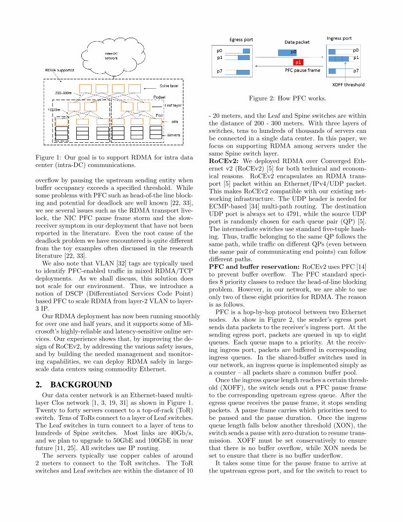
Figure 1: Our goal is to support RDMA for intra datacenter (intra-DC) communications.
overflow by pausing the upstream sending entity whenbuffer occupancy exceeds a specified threshold. Whilesome problems with PFC such as head-of-the line block-ing and potential for deadlock are well known [22, 33],we see several issues such as the RDMA transport live-lock, the NIC PFC pause frame storm and the slow-receiver symptom in our deployment that have not beenreported in the literature. Even the root cause of thedeadlock problem we have encountered is quite differentfrom the toy examples often discussed in the researchliterature [22, 33].
We also note that VLAN [32] tags are typically usedto identify PFC-enabled traffic in mixed RDMA/TCPdeployments. As we shall discuss, this solution doesnot scale for our environment. Thus, we introduce anotion of DSCP (Differentiated Services Code Point)based PFC to scale RDMA from layer-2 VLAN to layer-3 IP.
Our RDMA deployment has now been running smoothlyfor over one and half years, and it supports some of Mi-crosoft’s highly-reliable and latency-sensitive online ser-vices. Our experience shows that, by improving the de-sign of RoCEv2, by addressing the various safety issues,and by building the needed management and monitor-ing capabilities, we can deploy RDMA safely in large-scale data centers using commodity Ethernet.
2. BACKGROUNDOur data center network is an Ethernet-based multi-
layer Clos network [1, 3, 19, 31] as shown in Figure 1.Twenty to forty servers connect to a top-of-rack (ToR)switch. Tens of ToRs connect to a layer of Leaf switches.The Leaf switches in turn connect to a layer of tens tohundreds of Spine switches. Most links are 40Gb/s,and we plan to upgrade to 50GbE and 100GbE in nearfuture [11, 25]. All switches use IP routing.
The servers typically use copper cables of around2 meters to connect to the ToR switches. The ToRswitches and Leaf switches are within the distance of 10
Figure 2: How PFC works.
- 20 meters, and the Leaf and Spine switches are withinthe distance of 200 - 300 meters. With three layers ofswitches, tens to hundreds of thousands of servers canbe connected in a single data center. In this paper, wefocus on supporting RDMA among servers under thesame Spine switch layer.RoCEv2: We deployed RDMA over Converged Eth-ernet v2 (RoCEv2) [5] for both technical and econom-ical reasons. RoCEv2 encapsulates an RDMA trans-port [5] packet within an Ethernet/IPv4/UDP packet.This makes RoCEv2 compatible with our existing net-working infrastructure. The UDP header is needed forECMP-based [34] multi-path routing. The destinationUDP port is always set to 4791, while the source UDPport is randomly chosen for each queue pair (QP) [5].The intermediate switches use standard five-tuple hash-ing. Thus, traffic belonging to the same QP follows thesame path, while traffic on different QPs (even betweenthe same pair of communicating end points) can followdifferent paths.PFC and buffer reservation: RoCEv2 uses PFC [14]to prevent buffer overflow. The PFC standard speci-fies 8 priority classes to reduce the head-of-line blockingproblem. However, in our network, we are able to useonly two of these eight priorities for RDMA. The reasonis as follows.
PFC is a hop-by-hop protocol between two Ethernetnodes. As show in Figure 2, the sender’s egress portsends data packets to the receiver’s ingress port. At thesending egress port, packets are queued in up to eightqueues. Each queue maps to a priority. At the receiv-ing ingress port, packets are buffered in correspondingingress queues. In the shared-buffer switches used inour network, an ingress queue is implemented simply asa counter – all packets share a common buffer pool.
Once the ingress queue length reaches a certain thresh-old (XOFF), the switch sends out a PFC pause frameto the corresponding upstream egress queue. After theegress queue receives the pause frame, it stops sendingpackets. A pause frame carries which priorities need tobe paused and the pause duration. Once the ingressqueue length falls below another threshold (XON), theswitch sends a pause with zero duration to resume trans-mission. XOFF must be set conservatively to ensurethat there is no buffer overflow, while XON needs beset to ensure that there is no buffer underflow.
It takes some time for the pause frame to arrive atthe upstream egress port, and for the switch to react to

it. During this time, the upstream port will continue totransmit packets. Thus, the ingress port must reservebuffer space for each priority to absorb packets thatarrive during this “gray period”. This reserved buffer iscalled headroom. The size of the headroom is decided bythe MTU size, the PFC reaction time of the egress port,and most importantly, the propagation delay betweenthe sender and the receiver.
The propagation delay is determined by the distancebetween the sender and the receiver. In our network,this can be as large as 300 meters. Given that our ToRand Leaf switches have shallow buffers (9MB or 12MB),we can only reserve enough headroom for two losslesstraffic classes even though the switches support eighttraffic classes. We use one lossless class for real-timetraffic and the other for bulk data transfer.Need for congestion control: PFC works hop byhop. There may be several hops from the source serverto the destination server. PFC pause frames propagatefrom the congestion point back to the source if there ispersistent network congestion. This can cause problemslike unfairness and victim flow [42].
In order to reduce this collateral damage, flow basedcongestion control mechanisms including QCN [13], DC-QCN [42] and TIMELY [27] have been introduced. Weuse DCQCN, which uses ECN for congestion notifica-tion, in our network. We chose DCQCN because it di-rectly reacts to the queue lengths at the intermediateswitches and ECN is well supported by all the switcheswe use. Small queue lengths reduce the PFC generationand propagation probability.
Though DCQCN helps reduce the number of PFCpause frames, it is PFC that protects packets from beingdropped as the last defense. PFC poses several safety is-sues which are the primary focus of this paper and whichwe will discuss in Section 4. We believe the lessons wehave learned in this paper apply to the networks usingTIMELY as well.Coexistence of RDMA and TCP: In this paper,RDMA is designed for intra-DC communications. TCPis still needed for inter-DC communications and legacyapplications. We use a different traffic class (which isnot lossless), with reserved bandwidth, for TCP. Differ-ent traffic classes isolate TCP and RDMA traffic fromeach other.
3. DSCP-BASED PFCIn this section we examine the issues faced by the
original VLAN-based PFC and present our DSCP-basedPFC solution. VLAN-based PFC carries packet prior-ity in the VLAN tag, which also contains VLAN ID.The coupling of packet priority and VLAN ID createdtwo serious problems in our deployment, leading us todevelop a DSCP-based PFC solution.
Figure 3(a) shows the packet formats of the PFCpause frame and data packets in the original VLAN-based PFC. The pause frame is a layer-2 frame, and
(a) VLAN-based PFC.
(b) DSCP-based PFC.
Figure 3: The packet formats of VLAN-based PFC andDSCP-based PFC. Note that the PFC pause frame for-mat is the same in both Figure 3(a) and Figure 3(b).
does not have a VLAN tag. The VLAN tag for thedata packet has four parts: TPID which is fixed to0x8100, DEI (Drop Eligible Indicator), PCP (PriorityCode Point) which is used to carry packet priority, andVID (VLAN identifier) which carries the VLAN ID ofthe packet.
For our purpose, although we need only PCP, VIDand PCP cannot be separated. Thus, to support PFC,we have to configure VLAN at both the server and theswitch side. In order for the switch ports to supportVLAN, we need to put the server facing switch portsinto trunk mode (which supports VLAN tagged pack-ets) instead of access mode (which sends and receivesuntagged packets). The basic PFC functionality workswith this configuration, but it leads to two problems.
First, the switch trunk mode has an undesirable inter-action with our OS provisioning service. OS provision-ing is a fundamental service which needs to run whenthe server OS needs to be installed or upgraded, andwhen the servers need to be provisioned or repaired.For data centers at our scale, OS provisioning has tobe done automatically. We use PXE (Preboot eXecu-tion Environment) boot to install OS from the network.When a server goes through PXE boot, its NIC doesnot have VLAN configuration and as a result cannotsend or receive packets with VLAN tags. But sincethe server facing switch ports are configured with trunkmode, these ports can only send packets with VLANtag. Hence the PXE boot communication between the
server and the OS provisioning service is broken. Wetried several “hacks” to fix this problem, including let-ting the switches change the switch port configurationbased on the guessed state of the servers, and letting theNICs accept all the packets with or without VLAN tag.However, all these proved to be complex and unreliable,and needless to say, non-standard.
Second, we have moved away from a layer-2 VLAN,and all our switches including the ToR switches arerunning layer-3 IP forwarding instead of MAC-basedlayer-2 bridging. A layer-3 network has the benefits ofscalability, better management and monitoring, bettersafety, all public and standard instead of proprietaryprotocols. However, in a layer-3 network, there is nostandard way to preserve the VLAN PCP value whencrossing subnet boundaries.
In both problems, the fundamental issue is that VLAN-based PFC unnecessarily couples packet priority andthe VLAN ID. We broke this coupling by introducingDSCP-based PFC. Our key observation is that the PFCpause frames do not have a VLAN tag at all. The VLANtag in data packets is used only for carrying the datapacket priority. In the IP world, there is a standard andbetter way to carry packet priority information, whichis the DSCP field in the IP header.
The solution, as shown in Figure 3(b), is to move thepacket priority from the VLAN tag into DSCP. As wecan see, the change is small and only touches the datapacket format. The PFC pause frame format stays thesame. With DSCP-based PFC, data packets no longerneed to carry the VLAN tag, which solves both of theproblems mentioned earlier. The server facing ports nolonger need to be in trunk mode, which means thatPXE boot works without any issues. Also, the packetpriority information, in form of DSCP value, is correctlypropagated by IP routing across subnets.
Of course, DSCP-based PFC does not work for thedesigns that need to stay in layer-2, e.g., Fibre Channelover Ethernet (FCoE). This is not a problem for us sincewe do not have any layer-2 networks in our data centers.
DSCP-based PFC requires both NICs and switchesto classify and queue packets based on the DSCP valueinstead of the VLAN tag. In addition, the NIC needs tosend out data packets with the right DSCP value. For-tunately, the switch and NIC ASICs are flexible enoughto implement this. Internally, at each port, the switchor NIC maintains eight Priority Groups (PGs), witheach PG can be configured as lossless or lossy. If a PGi (i ∈ [0, 7]) is configured as lossless, once its ingressbuffer occupation exceeds the XOFF threshold, pauseframe with priority i will be generated. The mappingbetween DSCP values and PFC priorities can be flexibleand can even be many-to-one. In our implementation,we simply map DSCP value i to PFC priority i.
Our DSCP-based PFC specification is publicly avail-able, and is supported by all major vendors (Arista Net-works, Broadcom, Cisco, Dell, Intel, Juniper, Mellanox,etc.). We believe DSCP-based PFC provides a simpler
and more scalable solution than the original VLAN-based design for IP networks.
4. THE SAFETY CHALLENGESUse of PFC and RDMA transport lead to several
safety challenges. We now describe these challenges andthe solutions we devised to address them.
4.1 RDMA transport livelockRDMA transport protocol is designed around the as-
sumption that packets are not dropped due to networkcongestion. This is achieved by PFC in RoCEv2. How-ever, packet losses can still happen for various other rea-sons, including FCS errors, and bugs in switch hardwareand software [21]. Ideally, we want RDMA performanceto degrade gracefully in presence of such errors.
Unfortunately, we found that the performance of RDMAdegraded drastically even with a very low packet lossrate. We illustrate this with the following simple ex-periment. We connected two servers A and B, via asingle switch (W), and carried out three experimentsfor RDMA SEND, WRITE, and READ. In the first ex-periment, A used RDMA SENDs to send messages ofsize 4MB each to B as fast as possible. The second ex-periment was similar, except A used RDMA WRITE.In the third experiment B used RDMA READ to read4MB chunks from A as fast as possible. The switch wasconfigured to drop any packet with the least significantbyte of IP ID equals to 0xff. Since our NIC hardwaregenerates IP IDs sequentially, the packet drop rate was1/256 (0.4%).
We found that even with this low packet drop rate,the application level goodput was zero. In other words,the system was in a state of livelock – the link wasfully utilized with line rate, yet the application was notmaking any progress.
The root cause of this problem was the go-back-0algorithm used for loss recovery by the RDMA trans-port. Suppose A is sending a message to B. The mes-sage is segmented into packets 0, 1, · · · , i, · · · ,m. Sup-pose packet i is dropped. B then sends an NAK(i)to A. After A receives the NAK, it will restart sendingthe message from packet 0. This go-back-0 approachcaused live-lock. A 4MB message is segmented into4000 packets. Since the packet drop rate is a deter-ministic 1/256, one packet of the first 256 packets willbe dropped. Then the sender will restart from the firstpacket, again and again, without making any progress.
Note that TCP and RDMA transport make differentassumptions on the network. TCP assumes a best-effortnetwork, in which packets can be dropped. Thus, TCPstacks incorporate sophisticated retransmission schemessuch as SACK [24] to deal with packet drops. On theother hand, RDMA assumes a lossless network, henceour vendor chose to implement a simple go-back-0 ap-proach. In go-back-0, the sender does not need to keepany state for retransmission.

Figure 4: An example to show that the interaction between Ethernet packet flooding and PFC pause frame propa-gation can cause deadlock.
This experiment clearly shows that for large networklike ours, where packet losses can still occur despite en-abling PFC, a more sophisticated retransmission schemeis needed. Recall however, that the RDMA transport isimplemented in the NIC. The resource limitation of theNIC we use meant that we could not implement a com-plex retransmission scheme like SACK. SACK wouldalso be overkill, as packet drops due to network conges-tion have been eliminated by PFC.
Our solution is to replace the go-back-0 with a go-back-N scheme. In go-back-N, retransmission startsfrom the first dropped packet and the previous receivedpackets are not retransmitted. Go-back-N is not idealas up to RTT ×C bytes , where C is the link capacity,can be wasted for a single packet drop. But go-back-Nis almost as simple as go-back-0, and it avoids livelock.We worked with our NIC provider to implement thego-back-N scheme, and since doing that, we have notobserved livelock in our network. We recommend thatthe RDMA transport should implement go-back-N andshould not implement go-back-0.
4.2 PFC DeadlockWe once believed that our network is deadlock-free
because of its Clos network topology and up-down rout-ing [1, 3, 19]. In such a topology, when a source serversends a packet to a destination server, the packets firstclimb up to one of the common ancestors of the sourceand the destination, then go down the path to the desti-
nation. Hence there is no cyclic buffer dependency. Butto our surprise, we did run into PFC deadlock when weran a stress test in one of our test clusters.
As we will see later, this occurred because the unex-pected interaction between PFC and Ethernet packetflooding broke the up-down routing.
Before diving into the details of this example, let’sbriefly review how a ToR switch forwards an IP packetto a server. Typically servers connected to the sameToR are in the same IP subnet. This subnet is thenadvertised to the rest of the network, so the rest of thenetwork can forward packets to the ToR switch. Oncethe ToR receives an IP packet which belongs to oneof its servers, it needs to query two tables. One is theARP table from which the ToR switch can figure out theMAC address of the destination server. The second isthe MAC address table from which the ToR switch canfigure out with which physical port the MAC addressis associated. The ARP table is for layer-3 IP whereasthe MAC address table is for layer-2. The ARP table ismaintained by the ARP protocol. The switch watcheswhich packet comes from which port to establish theMAC address table.
Both tables use timeout to retire outdated entries.The typical timeout values for the ARP and MAC tablesare very different: 4 hours and 5 minutes, respectively.The reason for using such disparate timeout values isthat the overhead of refreshing the entries in the twotables is very different. The MAC table is automati-

cally refreshed by hardware as new packets are received,while the ARP table is updated by ARP packets, whichare handled by the switch CPU. Hence the ARP tablemaintenance is more costly and thus the ARP table hasa much longer timeout value. Such disparate timeoutvalues can lead to an “incomplete” ARP entry – i.e. aMAC address is present in the ARP table, but there isno entry in the MAC address table for that MAC ad-dress. When a packet destined to such a MAC addressarrives, the switch cannot figure out to which port toforward the packet. The standard behavior in this caseis for the switch to flood the packet to all its ports.
Below let’s use a simplified example as shown in Fig-ure 4 to illustrate how the deadlock happens. We as-sume all the packets in the example are lossless packetsprotected by PFC.
1. Server S1 is sending packets to S3 and S5 via path{T0, La, T1}. The purple packets are to S3 andthe black packets to S5. S3 is dead, so the purplepackets received at port T1.p3 are flooded to therest ports of T1 including p4. The egress queueof T1.p4 will drop the purple packets once theyare at the head of the queue since the destina-tion MAC does not match. But before that, thesepurple packets are queued there. Also T1.p2 iscongested due to incast traffic from S1 and othersources. Hence the black packets are queued inT1. As a result, the ingress port of T1.p3 beginsto pause the egress port of La.p1.
2. Consequently, as the black and purple packets buildup queues in La, the ingress port of La.p0 beginsto pause the egress port of T0.p2. For the samereason, T0.p0’s ingress port begins to pause S1.
3. Server S4 begins to send blue packets to S2 viapath {T1, Lb, T0}. S2, unfortunately, is also dead.Port T0.p3 then floods the blue packets to the restports including T0.p2. Since all packets, includingthe blue packets, at the egress port of T0.p2 cannotbe drained, the ingress port of T0.p3 begins topause Lb.p0.
4. As a result, the ingress port of Lb.p1 begins topause T1.p4, and T1.p1 begins to pause S4.
Note that T1.p3 will continue to pause La.p1 even ifthe black packets leave T1 to S5 after the congestion atT1.p2 is gone. This is because the purple packets cannotbe drained as T1.p4 is paused by Lb. A PFC pauseframe loop among the four switches is then formed. Adeadlock therefore occurs. Once the deadlock occurs, itdoes not go away even if we restart all the servers.
This deadlock is a concrete example of the well-knowncyclic buffer dependency (see [12, 18, 22, 36] and ref-erences therein). The cause of the cyclic dependency,however, is ‘new’. It is caused by the flooding behaviorof the switch. In an Ethernet switch, once the destina-tion MAC address of a packet is unknown, the packet is
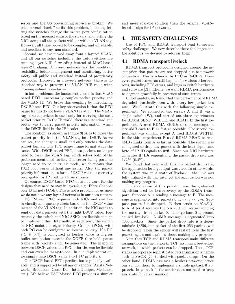
Figure 5: The PFC pause frame storm caused by themalfunctioning NIC of one single server (server 0).
flooded to all the ports except the receiving port. This‘legitimate’ behavior causes the dependency circle to beformed as we have shown in the above example.
We need to stop flooding for lossless packets to pre-vent deadlock from happening. There are several op-tions for us to choose when an ARP entry becomes in-complete (i.e., the IP address to MAC address mappingis there, but the MAC address to port number mappingis not). (1) We forward the packets to the switch CPUand let the switch CPU figure out what to do. (2) Weset up the timeout value of the MAC table to be longerthan that of the ARP table, so that an ARP entry can-not be incomplete. (3) We drop the lossless packets iftheir corresponding ARP entry is incomplete.
We have chosen option (3). Option (1) may increasethe switch CPU overhead. Option (2) needs to either re-duce the ARP table timeout value or increase the MACaddress table timeout value. If we reduce the ARP tabletimeout value, we increase the switch CPU overhead forARP handling. If we increase the MAC address tabletimeout value, we need longer time to tell when a serverbecomes disconnected from the switch. Option (3) is abetter way to prevent deadlock as it directly preventsthe cyclic buffer dependency.
The lesson we have learned from the PFC deadlock isthat broadcast and multicast are dangerous for a losslessnetwork. To prevent deadlock from happening, we rec-ommend that broadcast and multicast packets shouldnot be put into lossless classes.
4.3 NIC PFC pause frame stormPFC pause frames prevent packets from been dropped
by pausing the upstream devices. But PFC can causecollateral damage to innocent flows due to the head-of-line blocking. We illustrate the worst-case scenario inFigure 5 1:
1. The malfunctioning NIC of server 0 continuallysends pause frames to its ToR switch;
2. The ToR switch in turn pauses all the rest ports in-cluding all the upstream ports to the Leaf switches;
1The scenario involves a malfunctioning NIC.

3. The Leaf switches pause the Spine switches;
4. The Spine switches pause the rest of the Leaf switches;
5. The rest of the Leaf switches pause their ToR switches;
6. The ToR switches pause the servers that connectto them.
In this case, a single malfunctioning NIC may blockthe entire network from transmitting. We call this NICPFC pause frame storm, or PFC storm for abbrevia-tion. To our surprise, we observed PFC storms in ournetworks multiple times and PFC storms caused severalincidents which we will describe in Section 6.
The root-cause of the PFC storm problem is a bug inthe NIC’s receiving pipeline. The bug stopped the NICfrom handling the packets it received. As a result, theNIC’s receiving buffer filled, and the NIC began to sendout pause frames all the time.
We have worked with the NIC provider to fix this NICbug. Furthermore, to prevent PFC storms from hurtingthe network, we have implemented two watchdogs atboth the NIC and the ToR switches as follows.
On the NIC side, we worked with the NIC provider tobuild a PFC storm prevention watchdog. This is pos-sible because the NIC has a separate micro-controllerwhich can be used to monitor the NIC receiving sidepipeline. Once the NIC micro-controller detects the re-ceiving pipeline has been stopped for a period of time(default to 100ms) and the NIC is generating the pauseframes, the micro-controller will disable the NIC fromgenerating pause frames. Our experience with PFCstorm is that once the NIC enters the storm mode, theserver is disconnected from the network since the NICis not functioning well anymore. The NIC watchdog isnot able to rescue the server. Instead, its goal is to pre-vent the pause frame storms from hurting the rest ofthe network.
On the ToR switch side, we worked with the switchproviders to build a switch watchdog to monitor theserver facing ports. Once a server facing egress portis queuing packets which cannot be drained, and at thesame time, the port is receiving continuous pause framesfrom the NIC, the switch will disable the lossless modefor the port and discard the lossless packets to and fromthe NIC. Similar to the NIC side watchdog, it is toprevent pause frames from the malfunctioning NIC frompropagating into the network. Once the switch detectsthat the pause frames from the NIC disappear for aperiod of time (default to 200ms), it will re-enable thelossless mode for the port.
These two watchdogs are complementary to each other.One of them should be sufficient to stop the NIC PFCstorm. We have implemented both for double insurance.
Note that there is a small difference in the two watch-dog implementations. The switch watchdog will re-enable the lossless mode once pause frames are gone,whereas the NIC watchdog does not re-enable the loss-less mode. This is because we have observed once the
NIC enters the PFC storm mode, it never comes back.Hence re-enabling the lossless mode is not needed forthe NIC.
We also have observed that the NIC PFC storm prob-lem typically can be fixed by a server reboot. Henceonce the NIC is not functioning, our server manage-ment system will try to repair (reboot, reimage etc.)the server. Repairing takes tens of minutes. The NICwatchdog is to limit the damage of the problematic NICto hundreds of milliseconds before server repair kicksin. Once the server is repaired successfully and pauseframes from the servers are gone, the switch can re-enable the lossless mode for the corresponding switchport automatically.
Knowledgable readers may wonder about the interac-tions between the two watchdogs. Once the NIC watch-dog disables the NIC pause frames, the switch watchdogwill re-enable the lossless mode for the correspondingswitch port. The packets to the NIC will either droppedby the switch (if the MAC address of the NIC times out)or dropped by the NIC (since the NIC receiving pipelineis not functioning). In either case, the NIC PFC stormcannot cause damage to the whole network.
We recommend both switches and NICs should im-plement the watchdogs for NIC PFC storm prevention.
4.4 The Slow-receiver symptomIn our data centers, a server NIC is connected to a
ToR switch using a point-to-point cable. The NIC isconnected to the CPU and memory systems via PCIe.For a 40 GbE NIC, it uses PCIe Gen3x8 which provides64Gb/s raw bidirectional bandwidth which is more thanthe 40Gb/s throughput of the NIC. Hence there seemsto be no bottleneck between the switch and the serverCPU and memory. We thought that the server NICshould not be able to generate PFC pause frames tothe switch, because there is no congestion point at theserver side.
But this was not what we have observed. We foundthat many servers may generate up to thousands of PFCpause frames per second. Since RDMA packets do notneed the server CPU for processing, the bottleneck mustbe in the NIC. It turned out that this is indeed the case.The NIC has limited memory resources, hence it putsmost of the data structures including QPC (Queue PairContext) and WQE (Work Queue Element) in the mainmemory of the server. The NIC only caches a smallnumber of entries in its own memory. The NIC has aMemory Translation Table (MTT) which translates thevirtual memory to the physical memory. The MTT hasonly 2K entries. For 4KB page size, 2K MTT entriescan only handle 8MB memory.
If the virtual address in a WQE is not mapped inthe MTT, it results in a cache miss, and the NIC hasto replace some old entries for the new virtual address.The NIC has to access the main memory of the serverto get the entry for the new virtual address. All thoseoperations take time and the receiving pipeline has to
wait. The MTT cache miss will therefore slow down thepacket processing pipeline. Once the receiving pipelineis slowed down and the receiving buffer occupation ex-ceeds the PFC threshold, the NIC has to generate PFCpause frames to the switch.
We call this phenomenon the slow-receiver symptom.Though its damage is not as severe as the NIC PFCstorm, it may still cause the pause frames to propagateinto the network and cause collateral damage.
The slow-receiver symptom is a ‘soft’ bug caused bythe NIC design. We took two actions to mitigate it. Onthe NIC side, we used a large page size of 2MB insteadof 4KB. With a large page size, the MTT entry missbecomes less frequent. On the switch side, we enableddynamic buffer sharing among different switch ports.Compared with static buffer reservation, dynamic buffersharing statistically gives RDMA traffic more buffers.Hence even if the NICs are pausing the switch portsfrom time to time, the switches can absorb additionalqueue buildup locally without propagating the pauseframes back into the network. Compared with staticbuffer allocation, our experience showed that dynamicbuffer sharing helps reduce PFC pause frame propaga-tion and improve bandwidth utilization.
5. RDMA IN PRODUCTIONWe added new management and monitoring capabili-
ties to debug the various RDMA and PFC safety issuesdescribed in Section 4, and to detect RDMA relatedbugs and incidents. We now discuss these new capabili-ties which include the RDMA/PFC configuration mon-itoring, the PFC pause frame and lossless traffic moni-toring, and the active RDMA latency monitoring. Wealso present the latency and throughput measurements.
5.1 Configuration management and mon-itoring
To enable RDMA, we need to configure PFC at theswitch side, and RDMA and PFC at the server side.At the switch side, the PFC configuration is part of theQoS configuration. The PFC configuration has a globalpart which reserves buffer size, classifies packets intodifferent traffic classes based on the DSCP value, mapsdifferent traffic classes into different queues, and assignsdifferent bandwidth reservations for different queues.The PFC configuration also has a per port part whichenables PFC for every individual physical port.
At the server side, there are configurations to en-able/disable RoCEv2, PFC configuration, DCQCN con-figuration, and traffic configuration. In traffic configu-ration, users specify which type of traffic they would liketo put into PFC protection. The specification is basedon the destination transport port which is similar to theTCP destination port.
We have a configuration monitoring service to checkif the running configurations of the switches and theservers are the same as their desired configurations. Our
RDMA management and monitoring service handles thecomplexities introduced by the combinations of multi-ple switch types, multiple switch and NIC firmware ver-sions, and different configuration requirements for dif-ferent customers.
5.2 PFC pause frame and traffic monitor-ing
Besides configuration monitoring, we have also builtmonitoring for the PFC pause frames and the two RDMAtraffic classes. For pause frame, we monitor the numberof pause frames been sent and received by the switchesand servers. We further monitor the pause intervals atthe server side. Compared with the number of pauseframes, pause intervals can reveal the severity of thecongestion in the network more accurately. Pause in-tervals, unfortunately, are not available for the switcheswe currently use. We have raised the PFC pause in-terval monitoring requirement to the switching ASICproviders for their future ASICs.
For RDMA traffic monitoring, we collect packets andbytes been sent and received per port per priority, packetdrops at the ingress ports, and packet drops at theegress queues. The traffic counters can help us under-stand the RDMA traffic pattern and trend. The dropcounters help us detect if there is anything wrong forthe RDMA traffic: normally no RDMA packets shouldbe dropped.
5.3 RDMA PingmeshWe have developed an active latency measurement
service for RDMA similar to the TCP Pingmesh service[21]. We let the servers ping each other using RDMAand call the measurement system RDMA Pingmesh.RDMA Pingmesh launches RDMA probes, with pay-load size 512 bytes, to the servers at different locations(ToR, Podset, Data center) and logs the measured RTT(if probes succeed) or error code (if probes fail).
From the measured RTT of RDMA Pingmesh, we caninfer if RDMA is working well or not.
Our RDMA management and monitoring took a prag-matic approach by focusing on configurations, coun-ters, and end-to-end latency. We expect this approachworks well for the future 100G or higher speed networks.RDMA poses challenges for packet-level monitoring dueto the high network speed and NIC offloading, which weplan to address in our next step.
5.4 RDMA PerformanceIn what follows, we present the RDMA performance
results in both testbed and production networks.Latency reduction: Figure 6 shows the end-to-endlatency comparison of TCP and RDMA for a highly-reliable, latency-sensitive online service. This servicehas multiple instances in Microsoft global data centersand it has 20K servers in each data center. The mea-surements are from one of the data centers. At thetime of measurement, half of the traffic was TCP and
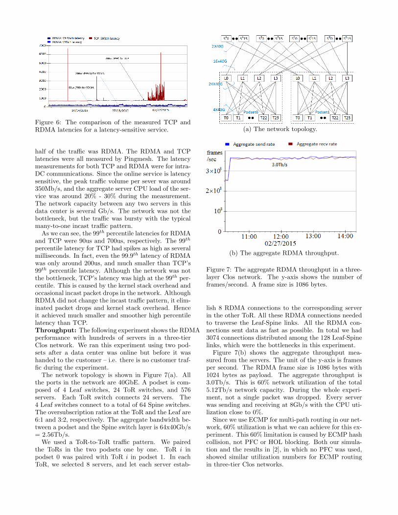
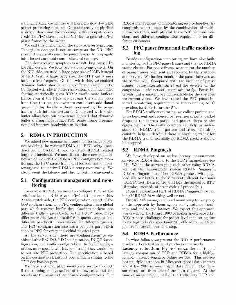
Figure 6: The comparison of the measured TCP andRDMA latencies for a latency-sensitive service.
half of the traffic was RDMA. The RDMA and TCPlatencies were all measured by Pingmesh. The latencymeasurements for both TCP and RDMA were for intra-DC communications. Since the online service is latencysensitive, the peak traffic volume per sever was around350Mb/s, and the aggregate server CPU load of the ser-vice was around 20% - 30% during the measurement.The network capacity between any two servers in thisdata center is several Gb/s. The network was not thebottleneck, but the traffic was bursty with the typicalmany-to-one incast traffic pattern.
As we can see, the 99th percentile latencies for RDMAand TCP were 90us and 700us, respectively. The 99th
percentile latency for TCP had spikes as high as severalmilliseconds. In fact, even the 99.9th latency of RDMAwas only around 200us, and much smaller than TCP’s99th percentile latency. Although the network was notthe bottleneck, TCP’s latency was high at the 99th per-centile. This is caused by the kernel stack overhead andoccasional incast packet drops in the network. AlthoughRDMA did not change the incast traffic pattern, it elim-inated packet drops and kernel stack overhead. Henceit achieved much smaller and smoother high percentilelatency than TCP.Throughput: The following experiment shows the RDMAperformance with hundreds of servers in a three-tierClos network. We ran this experiment using two pod-sets after a data center was online but before it washanded to the customer – i.e. there is no customer traf-fic during the experiment.
The network topology is shown in Figure 7(a). Allthe ports in the network are 40GbE. A podset is com-posed of 4 Leaf switches, 24 ToR switches, and 576servers. Each ToR switch connects 24 servers. The4 Leaf switches connect to a total of 64 Spine switches.The oversubscription ratios at the ToR and the Leaf are6:1 and 3:2, respectively. The aggregate bandwidth be-tween a podset and the Spine switch layer is 64x40Gb/s= 2.56Tb/s.
We used a ToR-to-ToR traffic pattern. We pairedthe ToRs in the two podsets one by one. ToR i inpodset 0 was paired with ToR i in podset 1. In eachToR, we selected 8 servers, and let each server estab-
(a) The network topology.
(b) The aggregate RDMA throughput.
Figure 7: The aggregate RDMA throughput in a three-layer Clos network. The y-axis shows the number offrames/second. A frame size is 1086 bytes.
lish 8 RDMA connections to the corresponding serverin the other ToR. All these RDMA connections neededto traverse the Leaf-Spine links. All the RDMA con-nections sent data as fast as possible. In total we had3074 connections distributed among the 128 Leaf-Spinelinks, which were the bottlenecks in this experiment.
Figure 7(b) shows the aggregate throughput mea-sured from the servers. The unit of the y-axis is framesper second. The RDMA frame size is 1086 bytes with1024 bytes as payload. The aggregate throughput is3.0Tb/s. This is 60% network utilization of the total5.12Tb/s network capacity. During the whole experi-ment, not a single packet was dropped. Every serverwas sending and receiving at 8Gb/s with the CPU uti-lization close to 0%.
Since we use ECMP for multi-path routing in our net-work, 60% utilization is what we can achieve for this ex-periment. This 60% limitation is caused by ECMP hashcollision, not PFC or HOL blocking. Both our simula-tion and the results in [2], in which no PFC was used,showed similar utilization numbers for ECMP routingin three-tier Clos networks.

Figure 8: The end-to-end RDMA latency jumped upas the experiment started and network throughput in-creased.
We unfortunately did not record the end-to-end RDMAlatency in the above throughput experiment. To fur-ther investigate the relationship between network la-tency and throughput, we conducted the following ex-periment in our testbed with a two-tier network. Wehad two ToR switches in this testbed. Each ToR switchhad 24 servers, and each ToR used 4 uplinks to con-nect to four Leaf switches. All the links were 40GbE.The oversubscription ratio was 6:1. We mimicked Thetraffic pattern in Figure 7. We chose 20 servers in ev-ery ToR and paired every server in one ToR with oneserver in another ToR and let every server-pair estab-lish 8 RDMA connections. Every server achieved 7Gb/ssending/receiving throughput. We show the RDMA la-tency measured in Pingmesh in Figure 8. Once theexperiment started, the end-to-end RDMA latencies in-creased from 50us at the 99th percentile and 80us at the99.9th percentile to 400us and 800us, respectively.
Note that the 99th percentile latency of TCP did notchange during the experiment in Figure 8. This is be-cause we put RDMA and TCP packets into two differentqueues in the switches. Hence RDMA and TCP did notinterfere with each other. We note that the 99th per-centile latency of TCP was 500us in Figure 8, whereasit was 700us in Figure 6. The difference was caused bythe fact that the servers in Figure 6 were servicing real-world workload whereas the servers in Figure 8 were al-most idle (except running the RDMA traffic generator).Figure 8 also demonstrated that the RDMA latency in-crease was due to the network congestion created by theRDMA traffic.
The above measurement results show that, comparedto TCP, RDMA achieves low latency and high through-put by bypassing the OS kernel and by eliminatingpacket drops. But RDMA is not a panacea for achiev-ing both low latency and high throughput. The RDMAlatency can still increase as the network becomes con-gested and queues build up.
6. EXPERIENCES
6.1 RDMA DeploymentRoCEv2 was a new technology to us when we began
this work three years ago. We were unaware of anylarge-scale RoCEv2 deployment at that time. Thoughthe benefits (zero packet drops, low latency, and lowCPU overhead) were attractive, we were concerned aboutthe maturity of RoCEv2. We devised a step-by-stepprocedure to onboard RDMA.
For the first step, we built a small lab network withtens of servers. This step helped us eliminate most ofthe bugs at early stage. In the second step, we usedtest clusters to improve the maturity of RoCEv2. Thetest clusters’ setup and management were the same astheir production counterparts. In the third step, weenabled RDMA in production networks at ToR levelonly. In the fourth step, we enabled PFC at the Podsetlevel, i.e., we enabled PFC in the ToR and Leaf switcheswithin the Podsets. In the last step, we enabled PFCup to the Spine switches. In every step when we carriedout deployment in production, we followed our safe de-ployment procedure to enable RDMA through severalphases in our global data centers.
This step-by-step procedure turned out to be effec-tive in improving the maturity of RoCEv2. The RDMAtransport livelock and most of the bugs were detectedin lab tests. The PFC deadlock and slow-receiver symp-tom were detected in the test clusters. Only the NICPFC pause frame storm and a few other bugs hit ourproduction networks.
Using the same management and monitoring for boththe test clusters and the production networks turnedout to be invaluable. It made our life easier as thetest clusters were always well managed. At the sametime, it let us thoroughly test RoCEv2 as well as themanagement and monitoring systems before RoCEv2went into production.
6.2 IncidentsNIC PFC storm. The following is one of the few NICPFC storm incidents we have encountered. In this inci-dent, one of our customers experienced a service avail-ability issue. Many of their servers became unavailableas shown in Figure 9(a). At the same time, we ob-served that many of the servers were continuously re-ceiving large number of PFC pause frames as shown byour monitoring system in Figure 9(b). The y-axis showsthe number of PFC pause frames sent/received in everyfive minutes.
We were able to trace down the origin of the PFCpause frames to a single server. That server was unre-sponsive and was in Failing (F) state as detected byour data center management system. But from theconnected ToR switch, we could observe the numberof pause frames from the server was always increasing,at more than two thousands pause frames per second.

(a) Server availability reduction. H (healthy), F (fail-ing), and P (probation) are server states.
(b) The PFC pause frames received by the servers.
Figure 9: An incident caused by the NIC PFC stormproblem of a single server.
We also observed that the server was not sending or re-ceiving any data packets. After we power-cycled thatserver, the server came back up and the pause frameswere gone.
NIC PFC storms happened very infrequently. Withhundreds of thousands of servers in production, thenumber of the NIC PFC storm events we have expe-rienced is still single digit. Nonetheless, once NIC PFCstorm happens, the damage is huge due to the PFCpause frame propagation. As we can see from this in-cident, half of our customers servers were affected andput into non healthy state.
After we put the NIC PFC storm prevention watch-dogs at both the servers and the ToR switches, we didnot experience NIC PFC storms anymore.Switch buffer misconfiguration. The ToR and Leafswitches we use have a small and limited buffer size of9MB or 12MB. To better utilize the scarce buffer space,we need to enable dynamic buffer sharing. In dynamicbuffer sharing, the ports allocate memory from a sharedbuffer pool. The shared buffer allocation per port pertraffic class is controlled by a parameter called α. Aslong as α × UB > Bp,i, where UB is the unallocatedshared buffer size and Bp,i is the allocated buffer size fortraffic class i of ingress port p, we can allocate memoryfrom the shared buffer for traffic class i from ingressport p. Hence a large α can help reduce the chance ofPFC pause frames from been generated. But a large αmay cause imbalanced and unfair buffer allocation.
We have found that the default α value (α = 116 )
for a type of ToR switch worked well in our productionnetwork. When we onboarded a new type of switchfrom the same switch provider, we took it for grantedthat it would use the same default settings as before.
Then in the midnight of 07/12/2015, we ran into anincident. As shown in Figure 10(a), the latencies ofmany latency-sensitive services increased dramatically.Also we have observed that many servers were receiving
(a) Services latency increase caused by the PFC pauseframe propagation. Every color here represents an im-pacted service.
(b) The PFC pause frames received by the servers.
Figure 10: An incident caused by the buffer misconfig-uration of a newly introduced switch type.
a large number of PFC pause frames, up to 60000 pauseframes in 5 minutes (Figure 10(b)).
Further analysis revealed the origins of the pause frames.The pause frames were generated by two ToR switches,then propagated into the rest of the network, and af-fected thousands of servers.
Why there were so many pause frames been gener-ated? There were two reasons. The first was the incasttraffic pattern. These two ToR switches hosted manychatty servers, which sent queries to more than onethousand servers simultaneously. Once the responsescame back to the chatty servers, incast happened, whichcreated network congestion condition for PFC pauseframe generation.
The second reason was that we found the α value ofthe new type of ToR switch was changed to 1
64 , thoughthese two types of switches were from the same provider.A much smaller α made the dynamic buffer allocatedto the congested ingress ports much smaller. Hence thePFC pause frames could be triggered much more easily.
We could not change the traffic pattern, so we tunedthe α value back to 1
16 for these switches.The lesson we learned from this incident is that PFC
pause frames did propagate and cause collateral damagein our production network. To reduce the damage, weneed to reduce PFC pause frames from being generated.Our work on the NIC PFC storm and the slow-receiversymptom prevent servers from been generating pauses.Moreover, parameter tuning of the dynamic buffer shar-ing and the per-flow based DCQCN [42] congestion con-trol reduce the pauses generated by the switches.

6.3 Lessons learned and discussionDuring the three years period of designing, building,
and deploying RoCEv2, we have learned several lessonswhich we share as follows.
Deadlock, livelock, and PFC pause frames prop-agation did happen. The PFC deadlock we met wasa surprise to us, as we once believed that our Clos-basednetwork topology was free of cyclic buffer dependencyhence free of deadlock. We did not expect the slow-server symptom, though we were fully aware that PFCbackpressure can cause PFC pause frame propagationin the network. We did not foresee the RDMA transportlivelock either. The lesson we learned is that a designworks in theory is not enough, as there may be manyhidden details which invalidate the design. We have touse well designed experiments, test clusters, and stagedproduction deployments, to verify the designs and tounveil the unexpected facets methodologically.
NICs are the key to make RDMA/RoCEv2work. Most of the RDMA/RoCEv2 bugs we ran intowere caused by the NICs instead of the switches. Wespent much more time on the NICs than on the switches.In hindsight, this happened for two reasons. The firstreason is because the NIC implements the most compli-cated parts of the RDMA functionalities, including theRDMA verbs and the RDMA transport protocol. As acomparison, the switch side functionalities are relativelysimple (e.g., PFC implementation) or well tested (e.g.,ECN implementation). The second reason is that theNICs we use are resource constrained. The NIC lever-ages the server’s DRAM to store its data structures anduses its own local memory as the cache. Cache manage-ment then becomes a big part of the NIC and introducesbugs as well as performance bottlenecks, e.g., the slow-receiver symptom.
Be prepared for the unexpected. Our experi-ences of running one of the largest data center networksin the world taught us that network incidents happen.From day one when we began to work on RoCEv2,we put RDMA/RoCEv2 management and monitoringas an indispensable part of the project. We upgradedour management and monitoring system for RDMA sta-tus monitoring and incidents handling at the same timewhen we worked on the DSCP-based PFC design andthe safety and performance bugs. As a result, when ourcustomers began to use RDMA, the RDMA manage-ment and monitoring capabilities were already in pro-duction. This RDMA management and monitoring sys-tem is essential for RDMA health tracking and incidenttroubleshooting. It helped us detect, localize, and root-cause the RoCEv2 bugs and incidents as we have shownin Sections 6.2 and 4.
Is lossless needed? RoCEv2 depends on a loss-less network to function well. In this work, we havedemonstrated that we indeed can build a lossless net-work using PFC, and all the real-world scalability andsafety challenges can be addressed. Looking forward
into the future, the question we would like to ask is:do we really need a lossless network to get the bene-fits of RoCEv2? Given the progress on programmablehardware, e.g., FPGA and FPGA integrated CPU [8],it may become feasible and economical to build muchfaster and more advanced transport protocols and for-ward error correction algorithms directly in commodityhardware, hence relieving RoCEv2 from been depend-ing on lossless network.
7. RELATED WORKThis paper focuses on how to safely deploy RoCEv2
on a large-scale. Besides RoCEv2, there are two otherRDMA technologies: Infiniband [6] and iWarp [30].
Infiniband is a complete networking protocol suite,which has its own layer-1 to layer-7 protocols. An Infini-band network is composed of multiple Infiniband sub-nets which are connected via Infiniband routers. Withina subnet, servers are connected via Infiniband switches.However, to the best of our knowledge, there are still noInfiniband routers in production. Hence Infiniband doesnot meet our scalability requirement. Furthermore, In-finiband is not compatible with Ethernet, which is thedominant networking technology for data centers.
iWarp runs RDMA over TCP/IP. The TCP/IP pro-tocol is offloaded to the NIC. Since TCP guaranteesreliable delivery even if some of the packets are dropped,iWarp does not necessarily need a lossless network. iWarphas one advantage over RoCE in that it can be use forinter-DC communications. But since iWarp uses TCPfor packet transmission, it faces the same issue of TCP:long latency caused by packet drops and retransmissiontimeout. As we have discussed in 6.3, we expect newtransport protocols different from the Infiniband trans-port and TCP to be introduced in the future driven bynew hardware innovations.
Deadlock is well studied in the literature and it iswell known cyclic buffer dependency is necessary fordeadlock [12, 18, 22, 33, 36]. Due to the specific Closnetwork topology, we once thought our network shouldbe free from deadlock since it should be free of cyclicbuffer dependency. But the ‘conspiracy’ of PFC andEthernet packet flooding has shown that deadlock canhappen in Clos networks.
TCP performance issues such as TCP incast [35, 38,39] and long latency tail [41] have been studied exten-sively. These solutions are still within the existing TCPframework. They either tune the retransmission timer(as in [35]), or control the TCP receiving window ([39]),or tune the ECN parameter ([38]). RDMA providesa different approach.Compared to [41] which still usesTCP, RDMA bypasses the OS kernel, so that the la-tency introduced by the kernel is eliminated. Our workshows that RDMA can be safely deployed at scale forintra-DC communications. As we have shown in Fig-ure 5.4, RDMA greatly reduces the high percentile la-tency compared with TCP.

RDMA has been used to build systems including stor-age, key-value stores, and distributed transaction sys-tems [17, 26, 28, 37]. Most of these systems use In-finiband or RoCE with tens of servers. In this paper,we have shown that we can scale RDMA to much largernetworks using RoCEv2. Hence much larger in-memorysystems can be built in the future.
8. CONCLUSIONIn this paper, we have presented our practices and ex-
periences in deploying RoCEv2 safely at large-scale inMicrosoft data centers. Our practices include the intro-ducing of DSCP-based PFC which scales RoCEv2 fromlayer-2 VLAN to layer-3 IP and the step-by-step on-boarding and deployment procedure. Our experiencesinclude the discoveries and resolutions of the RDMAtransport livelock, the RDMA deadlock, the NIC PFCstorm and the slow-receiver symptom. With the RDMAmanagement and monitoring in place, some of our highly-reliable, latency-sensitive services have been runningRDMA for over one and half years.
8.1 Future WorkThere are several directions for our next steps. The
hop-by-hop distance for PFC is limited to 300 meters.Hence RoCEv2 works only for servers under the sameSpine switch layer. To this end, RoCEv2 is not asgeneric as TCP. We need new ideas on how to extendRDMA for inter-DC communications.
Our measurement showed ECMP achieves only 60%network utilization. For TCP in best-effort networks,there are MPTCP [29] and per-packet routing [10] forbetter network utilization. How to make these designswork for RDMA in the lossless network context will bean interesting challenge.
The deadlock we have discovered in this paper re-minds us that deadlock in data centers may be worthyof more systematic study. Even though the up-downrouting in Clos network can prevent deadlock, designslike F10 [23] may break the assumption by introducinglocal rerouting. Many other network topologies [20] donot even have the up-down routing property. How candeadlocks be avoided in those designs?
Last but not least, we have shown that RDMA pro-vides low latency and high throughput by eliminatingOS kernel packet processing overhead and by relying ona lossless network. A lossless network, however, doesnot guarantee low latency. When network congestionsoccur, queues build up and PFC pause frames may stillbe generated. Both queues and PFC pause frames in-crease network latency. How to achieve low networklatency and high network throughput at the same timefor RDMA is still an open problem.
9. ACKNOWLEDGEMENTSYan Cai contributed to the design and experimen-
tations of DSCP-based PFC. Gang Cheng and Daniel
Firestone worked on the RDMA project at its earlystage. Yibo Zhu helped us on the RDMA transport live-lock experiments. We were supported by many mem-bers of Azure Networking. We have worked closely withour partners Charlie Gu, Sorabh Hamirwasia, MadhavPandya, Passaree Pasarj, Veselin Petrov, Xin Qian, Jun-hua Wang, Chenyu Yan to onboard RDMA for severalkey online services in Microsoft. We received technicalsupport from the engineers of Arista Networks, Broad-com, Cisco, Dell, and Mellanox. Our shepherd Nan-dita Dukkipati and the anonymous SIGCOMM review-ers gave us many constructive feedback and commentswhich improved the content and presentation of this pa-per. We thank them all.
10. REFERENCES[1] M. Al-Fares, A. Loukissas, and A. Vahdat. A
Scalable, Commodity Data Center NetworkArchitecture. In Proc. SIGCOMM, 2008.
[2] Mohammad Al-Fares, Sivasankar Radhakrishnan,Barath Raghavan, Nelson Huang, and AminVahdat. Hedera: Dynamic Flow Scheduling forData Center Networks. In NSDI, 2010.
[3] Alexey Andreyev. Introducing Data CenterFabric, The Next-generation Facebook DataCenter Network. https://code.facebook.com/posts/360346274145943/,Nov 2014.
[4] Hadoop. http://hadoop.apache.org/.
[5] Infiniband Trade Association. RoCEv2.https://cw.infinibandta.org/document/dl/7781,September 2014.
[6] Infiniband Trade Association. InfiniBandTMArchitecture Specification Volume 1 Release 1.3,March 2015.
[7] Luiz Barroso, Jeffrey Dean, and Urs Holzle. WebSearch for a Planet: The Google ClusterArchitecture. IEEE Micro, March-April 2003.
[8] Diane Bryant. Disrupting the Data Center toCreate the Digital Services Economy.https://communities.intel.com/community/itpeernetwork/datastack/blog/2014/06/18/disrupting-the-data-center-to-create-the-digital-services-economy.
[9] Brad Calder et al. Windows Azure Storage: AHighly Available Cloud Storage Service withStrong Consistency. In SOSP, 2011.
[10] Jiaxin Cao et al. Per-packet Load-balanced,Low-Latency Routing for Clos-based Data CenterNetworks. In ACM CoNEXT, 2013.
[11] Cisco. Cisco Nexus 3232C Switch Data Sheet.http://www.cisco.com/c/en/us/products/collateral/switches/nexus-3232c-switch/datasheet-c78-734883.html.
[12] William Dally and Charles Seitz. Deadlock-FreeMessage Routing in Multiprocessor

Interconnection Networks. IEEE trans.Computers, C-36(5), 1987.
[13] IEEE DCB. 802.1Qaz - Quantized CongestionNotification.http://www.ieee802.org/1/pages/802.1au.html.
[14] IEEE DCB. 802.1Qbb - Priority-based FlowControl.http://www.ieee802.org/1/pages/802.1bb.html.
[15] Jeffrey Dean and Luiz Andre Barroso. The Tail atScale. CACM, Februry 2013.
[16] Jeffrey Dean and Sanjay Ghemawat. MapReduce:Simplified Data Processing on Large Clusters. InOSDI, 2004.
[17] Aleksandar Dragojevic et al. No compromises:distributed transactions with consistency,availability, and performance. In SOSP, 2015.
[18] Jose Duato. A Necessary and Sufficient Conditionfor Deadlock-Free Routing in Cut-Through andStore-and-Forward Networks. IEEE trans Paralleland Distributed Systems, 7(8), 1996.
[19] Albert Greenberg et al. VL2: A Scalable andFlexible Data Center Network. In SIGCOMM,August 2009.
[20] Chuanxiong Guo et al. BCube: a highperformance, server-centric network architecturefor modular data centers. In SIGCOMM, 2009.
[21] Chuanxiong Guo et al. Pingmesh: A Large-ScaleSystem for Data Center Network LatencyMeasurement and Analysis. In ACM SIGCOMM,2015.
[22] Mark Karol, S. Jamaloddin Golestani, and DavidLee. Prevention of Deadlocks and Livelocks inLossless Backpressured Packet Networks.IEEE/ACM trans Networking, 11(6), Dec 2003.
[23] Vincent Liu, Daniel Halperin, ArvindKrishnamurthy, and Thomas Anderson. F10: AFault-Tolerant Engineered Network. In NSDI,2013.
[24] M. Mathis, J. Mahdavi, S. Floyd, andA. Romanow. TCP Selective AcknowledgmentOptions, 1996. IETF RFC 2018.
[25] Mellanox. ConnectX-4 EN Adapter CardSingle/Dual-Port 100 Gigabit Ethernet Adapter.http://www.mellanox.com/page/productsdyn?product family=204&mtag=connectx 4 en card.
[26] Christopher Mitchell, Yifeng Geng, and JinyangLi. Using One-Sided RDMA Reads to Build aFast, CPU-Efficient Key-Value Store. In USENIXATC, 2013.
[27] Radhika Mittal et al. TIMELY: RTT-basedCongestion Control for the Datacenter. In ACMSIGCOMM, 2015.
[28] Diego Ongaro, Stephen M. Rumble, Ryan
Stutsman, John Ousterhout, and MendelRosenblum. Fast Crash Recovery in RAMCloud.In SOSP, 2013.
[29] Costin Raiciu, Sebastien Barre, ChristopherPluntke, Adam Greenhalgh, Damon Wischik, andMark Handley. Improving DatacenterPerformance and Robustness with Multipath Tcp.In SIGCOMM, 2011.
[30] R. Recio, B. Metzler, P. Culley, J. Hilland, andD. Garcia. A Remote Direct Memory AccessProtocol Specification. IETF RFC 5040, October2007.
[31] Arjun Singh et al. Jupiter Rising: A Decade ofClos Topologies and Centralized Control inGoogle’s Datacenter Network. In SIGCOMM,2015.
[32] IEEE Computer Society. 802.1Q - 2014: VirtualBridged Local Area Networks, 2014.
[33] Brent Stephens, Alan L. Cox, Ankit Singla, JohnCarter, Colin Dixon, and Wesley Felter. PracticalDCB for Improved Data Center Networks. InInfocom, 2014.
[34] D. Thaler and C. Hopps. Multipath Issues inUnicast and Multicast Next-Hop Selection, 2000.IETF RFC 2991.
[35] Vijay Vasudevan et al. Safe and EffectiveFine-grained TCP Retransmissions for DatacenterCommunication. In SIGCOMM, 2009.
[36] Freek Verbeek and Julien Schmaltz. A Fast andVerified Algorithm for Proving Store-and-ForwardNetworks Deadlock-Free. In Proceedings of The19th Euromicro International Conference onParallel, Distributed and Network-BasedComputing (PDP’11), 2011.
[37] Xingda Wei, Jiaxin Shi, Yanzhe Chen, RongChen, and Haibo Chen. Fast In-memoryTransaction Processing using RDMA and HTM.In SOSP, 2015.
[38] Haitao Wu et al. Tuning ECN for Data CenterNetworks. In ACM CoNEXT, 2012.
[39] Haitao Wu, Zhenqian Feng, Chuanxiong Guo, andYongguang Zhang. ICTCP: Incast CongestionControl for TCP in Data Center Networks. InACM CoNEXT, 2010.
[40] Matei Zaharia et al. Resilient DistributedDatasets: A Fault-Tolerant Abstraction forIn-Memory Cluster Computing. In NSDI, 2012.
[41] David Zats, Tathagata Das, Prashanth Mohan,Dhruba Borthakur, and Randy Katz. DeTail:Reducing the Flow Completion Time Tail inDatacenter Networks. In SIGCOMM, 2012.
[42] Yibo Zhu et al. Congestion Control forLarge-Scale RDMA deployments. In ACM
SIGCOMM, 2015.